

Page 1
R410A
4 . CEILING TYPE :
AB 30FBAG, AB 30UBAG
AB 36FBAG, AB 36UBAG
D2D_AB003E/01
2005.12.26
Page 2

4-1. FEATURE
MODELS :
AB 30FBAG / AO 30FNBWL
AB 30UBAG / AO 30UNBWL
AB 36FBAG / AO 36FNAXT
AB 36UBAG / AO 36UNAXT
FEATURES
CEILING TYPE AB30-36
Installation
OPEN SPACE CONCEALED
Wide air flow
WALL MOUNTED
(for high-ceilinged room)
Fresh-air intake
Slender shape
A slender shape with curves harmonizes
Wide air flow
perfectly with the room interior.
Long-life filter
High efficiency long-life filter that extends the cleaning
cycle up to 2 times that of the current model is standard.
INDOOR
Slender
OUTDOOR
CEILING TYPE AB30-36
Filter
Double auto swing
VERTICAL HORIZONTAL
SWING
Others
Auto Restart
Detachable and Washable Open Panel
SWING
- (04 - 01) -
Page 3
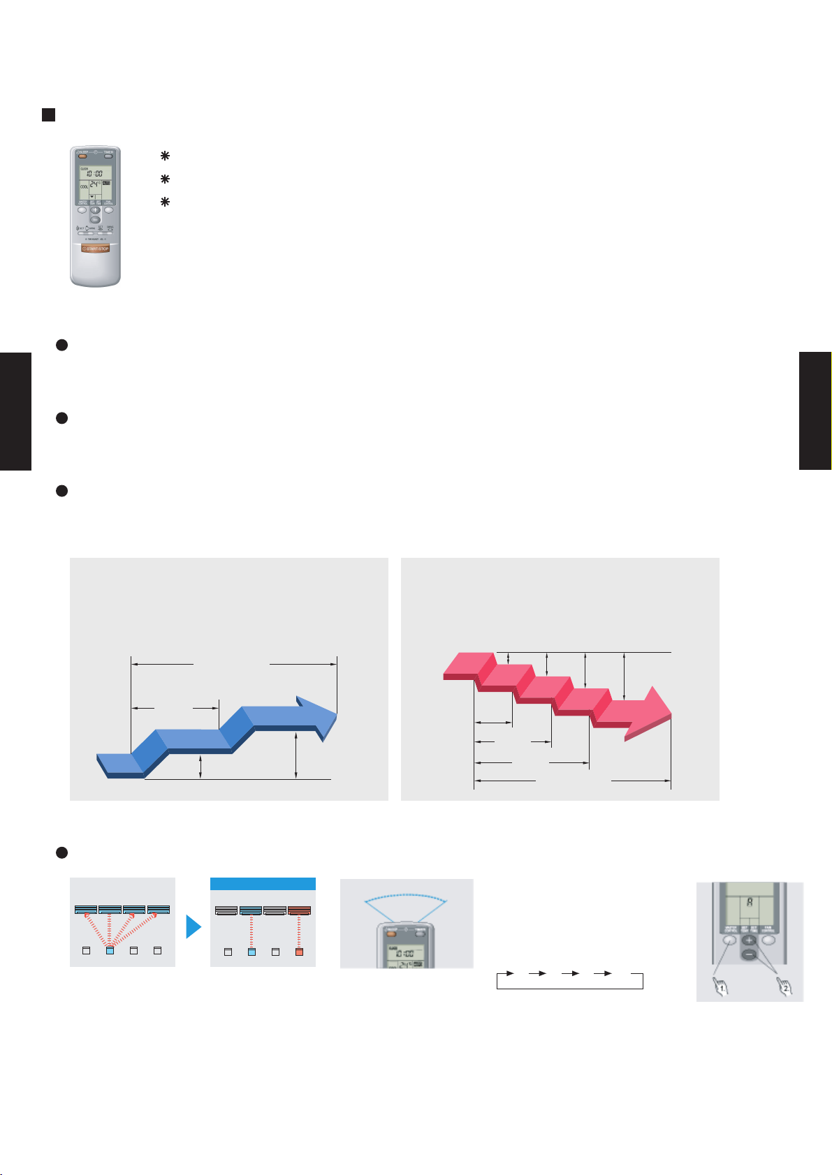
4-2. REMOTE CONTROLLER
4-2-1.
FEATURES
CEILING TYPE AB30-36
WIRELESS REMOTE CONTROLLER
Four kinds of timer setup (ON / OFF / PROGRAM / SLEEP) are possible.
Four kinds of timers. Easy operation.
Easy to change transmission code (4 patterns) by button operation.
Built-in timers
Select from four different timer programs (On/Off/Program/Sleep).
Program timer
The program timer operates the ON and OFF timer once within a 24 hour period.
CEILING TYPE AB30-36
Sleep timer
The sleep timer function automatically corrects the temperature thermostat setting according to
the time setting to prevent excessive cooling and heating while sleeping.
Cooling operation/dry operation
When the sleep timer is set, the set temperature
automatically rises 1 °C every hour. The set
temperature can rise up to a maximum of 2 °C.
Timer setting
60min.
1 °C
2 °C
Heating operation
When the sleep timer is set, the set temperature
automatically drops 1 °C every 30 minutes. The
set temperature can drop to a maximum of 4 °C.
1 °C
2 °C
3 °C
4 °C
30min.
60min.
90min.
Timer setting
Easy operation
After code change
Mixed-up
• Code selector switch eliminates unit
being wrongly switched.
(Up to 4 codes can be set.)
A B C D
A B
C
D
•Wide and precise
transmitting range.
1. Press the MASTER CONTROL
button for more than five seconds
to start the code change.
2. Press the (+) or (-) button to
select the desired code.
A B C D
3. Press the MASTER CONTROL
button again to end the code
change.
- (04 - 02) -
Page 4
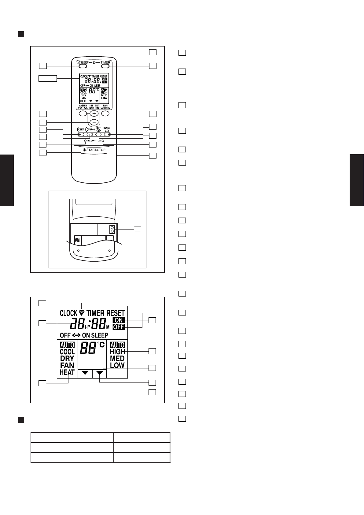
FUNCTIONS
CEILING TYPE AB30-36
Display
3
2
9
10
13
1
TEST
RUN
15
11
12
14
5
1
START/STOP button
Pressed to start and stop operation
64
2
Set temp./Set time buttons/Set remote controller
custom code buttons
Sets the indoor temp./Sets the current time and on-off time
/Set R.C. custom code
3
Master control button/
7
8
Selects the operating mode (AUTO, HEAT, FAN, COOL, DRY).
Start/end R.C. custom code change. (Max. 4 types)
4
Sleep timer button
Pressed to select sleep timer.
5
Signal transmitter
6
Timer button
Pressed to select the timer mode. (OFF TIMER, ON TIMER,
PROGRAM TIMER, TIMER RESET)
7
Fan control button
Selects the fan speed (AUTO, LOW, MED, HIGH).
8
Battery compartment lid
9
Air flow direction vertical set button
10
Air flow direction vertical swing button
Code change
CEILING TYPE AB30-36
Display panel
16
17
18
SPECIFICATION
19
20
21
22
23
11
Air flow direction horizontal swing button
12
Air flow direction horizontal set button
13
Time adjust button
Sets the current time.
14
ACL button
Used when replacing batteries or change the code.
15
Test run button
Used when testing the air conditioner after installation.
16
Transmit indicator
17
Clock display
18
Master control display
19
Timer mode display
20
Fan speed display
21
Set temperature display
22
Timer set indicator
23
Temperature set indicator
SIZE (H x W x D mm) 160 x 56 x 20
WEIGHT ( g ) 120
ACCESSORY Holder
- (04 - 03) -
Page 5
4-3. SPECIFICATIONS
AB 30FBAG AB 30UBAG
AO 30FNBWL AO 30UNBWL
Fin Pitch
Fin Pitch
0 to 43 0 to 43
-7 to 24
Specifications are based on the following conditions.
REMOTE CONTROLLER TYPE
TYPE
REFRIGERANT OIL
REFRIGERANT
TYPE
OPERATION(OUTDOOR)
°C
NET
GROSS
mm
kg(lbs)
NET /
GROSS
DIMENSIONS
H × W × D
OUTDOOR
Coil
Fin
HEAT
EXCHANGER
TYPE
FinmmRows × Stages
mm
CASING COLOR
TYPE
MODEL NAME
POWER SOURCE
COOLING
RATED
AVAILABLE VOLTAGE RANGE
CAPACITY
RATED
COP
STARTING CURRENT
INDOOR
OUTDOOR
HEATING
kW
INPUT POWER
INDOOR
Coil
CURRENT
MOISTURE REMOVAL
INDOOR
TYPE
INDOOR
kW/kW
A
EER
OUTDOOR
FAN MOTOR OUTPUT
W
STARTING METHOD
FAN SPEED
COOL/HEAT
NOISE LEVEL
(SOUND
PRESSURE)
COOL/HEAT
OUTDOOR
PIPE
SIZE
mm
CONNECTION METHOD
MAX HEIGHT
MAX LENGTH
WEIGHT
AIR
CIRCULATION
COOL/HEAT
m3/h
dB(A)
INDOOR
OUTDOOR
r.p.m
COMPRESSOR
FAN TYPE × Q'ty
Rows × Stages
DRAIN PIPE
MATERIAL
SIZE
Sirocco × 4
Propeller × 1
3.0(6.3)
230V 50Hz
198-264V 50Hz
16067ROTARY
2200
Permanent Starting Condenser
Copper tube
Aluminium
2 × 12
1.3
252 × 1350 × 26.6
Copper tube
Aluminium
2 × 38
1.3
798 × 900 × 36.38
White(5Y9/0.5NN)
Beige(10YR7.5/1.0NN)
240 × 1660 × 700
830 × 900 × 330
318 × 1800 × 790
970 × 1050 × 445
48 / 61 ( 106 / 134)
FLARE
9.52(3/8 inc.)
Outer diameter 25.6 / Inner diameter 22.0
CEILING MODELS
2300
POE
WIRELESS
ABS
15.88(5/8 inc.)
30 (chargeless:7.5)
15
R410A
COOLING TYPE HEAT PUMP TYPE
CEILING TYPE AB30-36
EUROPEAN ENERGY LABEL COOLING C C
kW 8.40 8.40
BTU/h 28700 28700
kW - 9.50
BTU/h - 32400
COOLING RATED 2.95 2.95
HEATING RATED - 2.78
COOLING RATED 13.6 13.6
HEATING RATED - 13.1
A 70 70
COOLING 2.85 2.85
HEATING - 3.42
l/h (pints/h)
High 1450/- 1450/1450
Med 1280/- 1280/1280
Low 980/- 980/980
Quiet - -
High 3300/- 3300/3300
Low 1600/- 1600/1600
High 850/- 850/850
Med 750/- 750/750
Low 600/- 600/600
Quiet - -
High 780/- 780/780
Low 400/- 400/400
INDOOR
OUTDOOR
INDOOR
OUTDOOR
High 42/- 42/43
Med 39/- 39/39
Low 35/- 35/35
53/- 53/54
CEILING TYPE AB30-36
OUTPUT W
Coil Dimensions
Coil Dimensions
INDOOR
INDOOR
OUTDOOR
INDOOR
OUTDOOR
INDOOR
OUTDOOR 68 / 74 (150 / 163) 69 / 75 (152 / 165)
OUTDOOR
LIQUID
GAS
m
m
CHARGE g
COOLING
HEATING -
Note:
Cooling: Indoor temperature of 27 °CDB / 19 °CWB,and outdoor temperature of 35 °CDB/24 °CWB.
Heating: Indoor temperature of 20 °CDB / 15 °CWB,and outdoor temperature of 7 °CDB/6 °CWB.
Pipe length : 7.5 m, Height difference : 0 m.(Outdoor unit - Indoor unit)
mm
- (04 - 04) -
Page 6
COOLING TYPE HEAT PUMP TYPE
AB 36FBAG AB 36UBAG
AO 36FNAXT AO 36UNAXT
Upper fan : 780 / Lower fan : 780 / -
Upper fan : 780/780
Lower fan : 780/780
Fin Pitch
1 × 54 2 × 54
Fin Pitch
1.3 1.3
0 to 43 0 to 43
-10 to 24
Specifications are based on the following conditions.
9.52(3/8 inc.)
Outer diameter 25.6 / Inner diameter 22.0
CEILING MODELS
POE
WIRELESS
ABS
15.88(5/8 inc.)
50 (chargeless:20)
30
R410A
318 × 1800 × 790
1305 × 1050 × 445
48 / 61 ( 106 / 134)
FLARE
White(5Y9/0.5NN)
Beige(10YR7.5/1.0NN)
240 × 1660 × 700
1165 × 900 × 330
1.45
252 × 1350 × 39.9
Copper tube
Aluminium
Three Phase
Copper tube
Aluminium
3 × 12
160
67 × 2
TWIN ROTARY
3000
3N 400V 50Hz
3N 342-457V 50Hz
Sirocco × 4
Propeller × 2
4.0(8.5)
DRAIN PIPE
MATERIAL
SIZE
WEIGHT
AIR
CIRCULATION
COOL/HEAT
m3/h
dB(A)
INDOOR
OUTDOOR
r.p.m
COMPRESSOR
FAN TYPE × Q'ty
Rows × Stages
PIPE
SIZE
mm
CONNECTION METHOD
MAX HEIGHT
MAX LENGTH
OUTDOOR
FAN MOTOR OUTPUT
W
STARTING METHOD
FAN SPEED
COOL/HEAT
NOISE LEVEL
(SOUND
PRESSURE)
COOL/HEAT
OUTDOOR
INDOOR
Coil
CURRENT
MOISTURE REMOVAL
INDOOR
TYPE
INDOOR
kW/kW
A
EER
COP
STARTING CURRENT
INDOOR
OUTDOOR
HEATING
kW
INPUT POWER
TYPE
MODEL NAME
POWER SOURCE
COOLING
RATED
AVAILABLE VOLTAGE RANGE
CAPACITY
RATED
DIMENSIONS
H × W × D
OUTDOOR
Coil
Fin
HEAT
EXCHANGER
TYPE
FinmmRows × Stages
mm
CASING COLOR
NET
GROSS
mm
kg(lbs)
NET /
GROSS
REMOTE CONTROLLER TYPE
TYPE
REFRIGERANT OIL
REFRIGERANT
TYPE
OPERATION(OUTDOOR)
°C
CEILING TYPE AB30-36
EUROPEAN ENERGY LABEL COOLING C B
kW 10.5 10.5
BTU/h 35800 35800
kW - 11.8
BTU/h - 40300
COOLING RATED 3.74 3.48
HEATING RATED - 3.45
COOLING RATED 6.2 5.9
HEATING RATED - 6.2
A 37 37
COOLING 2.81 3.02
HEATING - 3.42
l/h (pints/h)
High 1660/- 1660/1660
Med 1500/- 1500/1500
Low 1270/- 1270/1270
Quiet - -
High 7000/- 6100/6100
Low - -
High 1000/- 1000/1000
Med 900/- 900/900
Low 750/- 750/750
Quiet - -
High
Low - -
INDOOR
OUTDOOR
INDOOR
OUTDOOR
High 45/- 45/45
Med 42/- 42/42
Low 37/- 37/37
54/- 54/55
CEILING TYPE AB30-36
OUTPUT W
Coil Dimensions
Coil Dimensions
INDOOR
OUTDOOR
INDOOR
OUTDOOR
INDOOR
OUTDOOR
INDOOR
OUTDOOR 80 / 87 (176 / 192) 94 / 101 (207 / 223)
LIQUID
GAS
m
m
CHARGE g 2000 3200
COOLING
HEATING -
1134 × 900 × 18.19 1134 × 900 × 36.38
Note:
Cooling: Indoor temperature of 27 °CDB / 19 °CWB,and outdoor temperature of 35 °CDB/24 °CWB.
Heating: Indoor temperature of 20 °CDB / 15 °CWB,and outdoor temperature of 7 °CDB/6 °CWB.
Pipe length : 7.5 m, Height difference : 0 m.(Outdoor unit - Indoor unit)
mm
- (04 - 05) -
Page 7
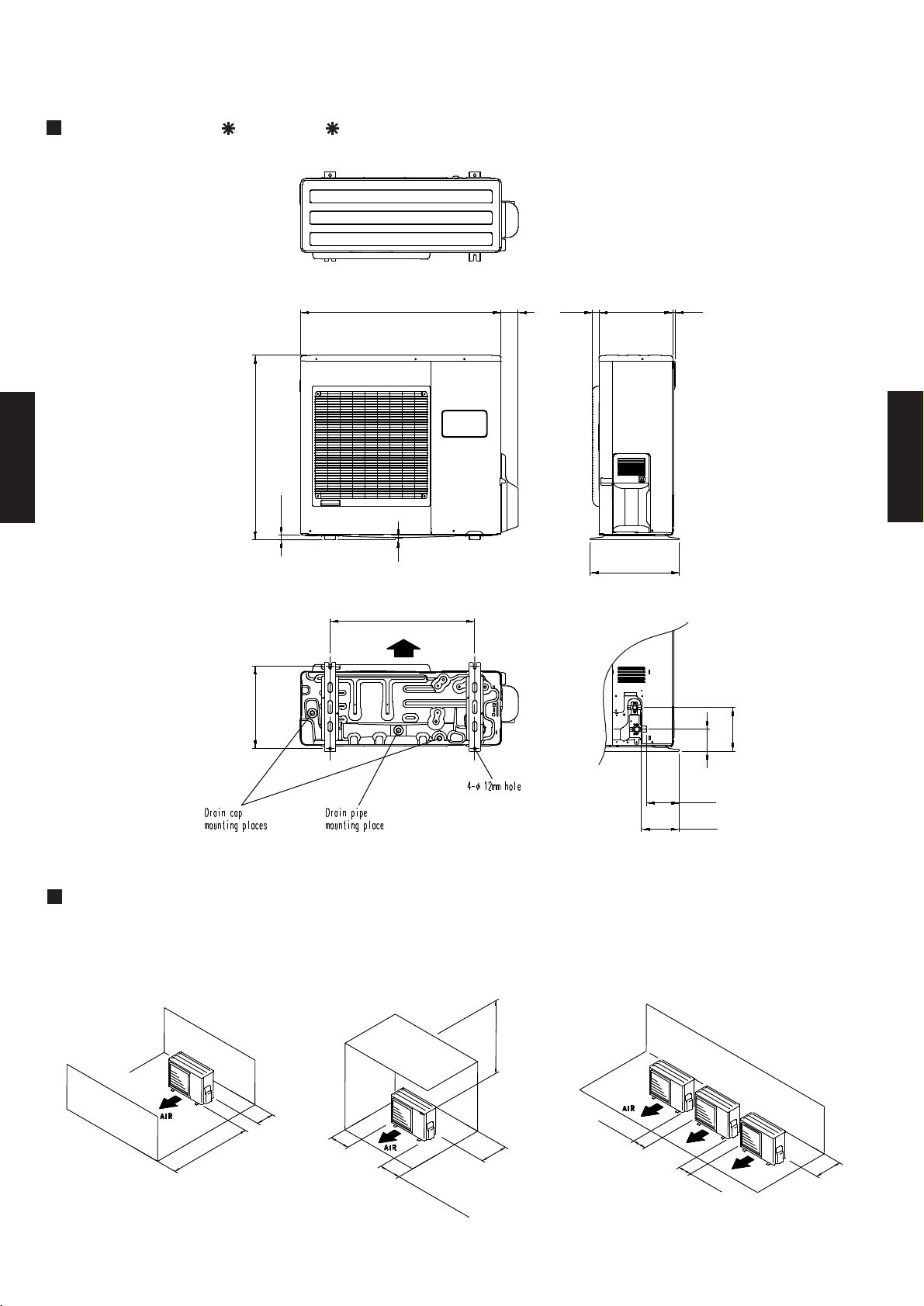
4-4. DIMENSIONS
4-4-1. OUTDOOR UNIT
CEILING TYPE AB30-36
MODELS : AO 30F, AO 30U
Top view
830
21
Front view
900
9
650
Air flow
(Unit : mm)
77
31 330
400
12
CEILING TYPE AB30-36
Side view
370
MOUNTING POSITION
When there are obstacles at the
back or front sides.
100 mm
or more
600 mm
or more
100 mm
or more
603
Bottom view
When there are obstacles at the
back, side(s), and top.
600 mm or more
300 mm
250
(
mm or
S
er
v
i
c
e s
more
pac
e)
or more
196
99
147
170
When there are obstacles at the
back, side with the installation of
more than one unit.
250 mm
or more
250 mm
or more
300 mm
or more
- (04 - 06) -
Page 8
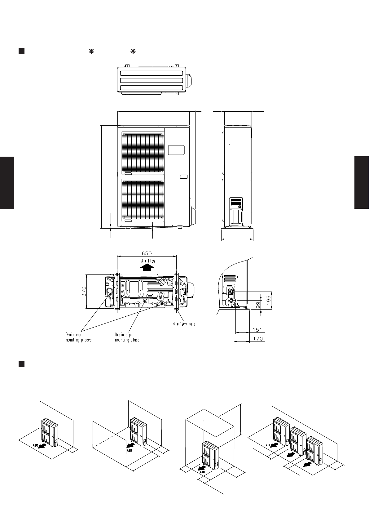
MODELS : AO 36F, AO 36U
(Unit : mm)
CEILING TYPE AB30-36
1165
21
Top view
Front view
3177900 330 12
CEILING TYPE AB30-36
9
400
Side view
MOUNTING POSITION
When there are
obstacles at the
back or front side.
When there are obstacles
at the back and front sides.
100 mm
or more
Bottom view
100 mm
or more
600 mm
or more
100 to 300 mm *
When there are obstacles at
the back, side(s), and top.
600 to 1000 mm
250 mm
or more
250 mm
(
Se
r
v
i
c
e
* If the space is larger than that is stated, the
condition will be the same as that there are no
obstacles.
300 mm
or more
or
mo
s
pac
r
e
e)
When there are obstacles
at the back side with the
installation of more than
one unit.
300 mm
250 mm
or more
or more
- (04 - 07) -
Page 9
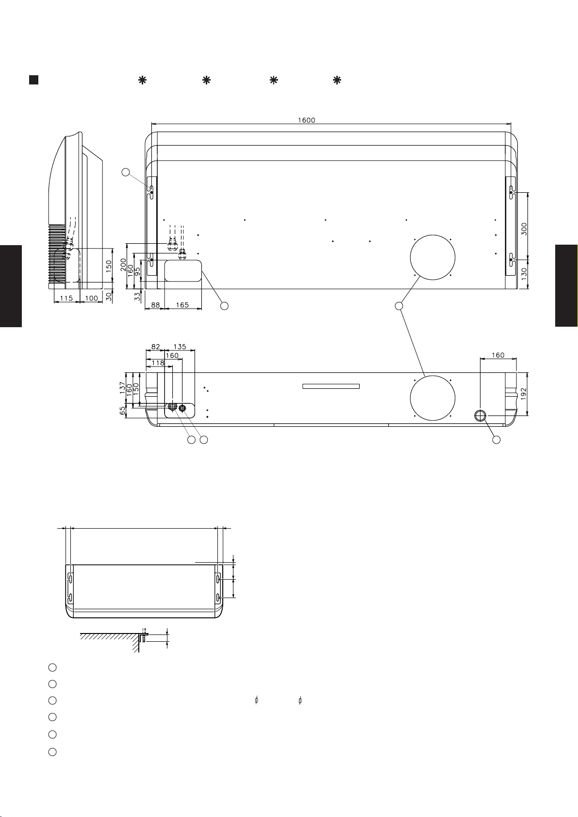
4-4-2. INDOOR UNIT
CEILING TYPE AB30-36
MODELS : AB 30F, AB 30U, AB 36F, AB 36U
6
Rear view
Side view
(Unit : mm)
45
CEILING TYPE AB30-36
1 2 3
Suspension bolt pitch
30 30
INDOOR UNIT (TOP VIEW)
INDOOR UNIT
1
Refrigerant piping flare connection (Gas)
2
Refrigerant piping flare connection (Liquid)
3
Drain piping connection (Drain pipe : I.D. 22 O.D. 25.6)
4
Knock out hole for fresh air
1,600
Dimensions
(Space Required
for Installation)
10
155
300
Suspension bolt
should extend
outward 30 to 75.
Bottom view
5
Knock out hole for refrigerant piping
6
Hole for lifting bolt (Use M10 screw bolt)
- (04 - 08) -
Page 10
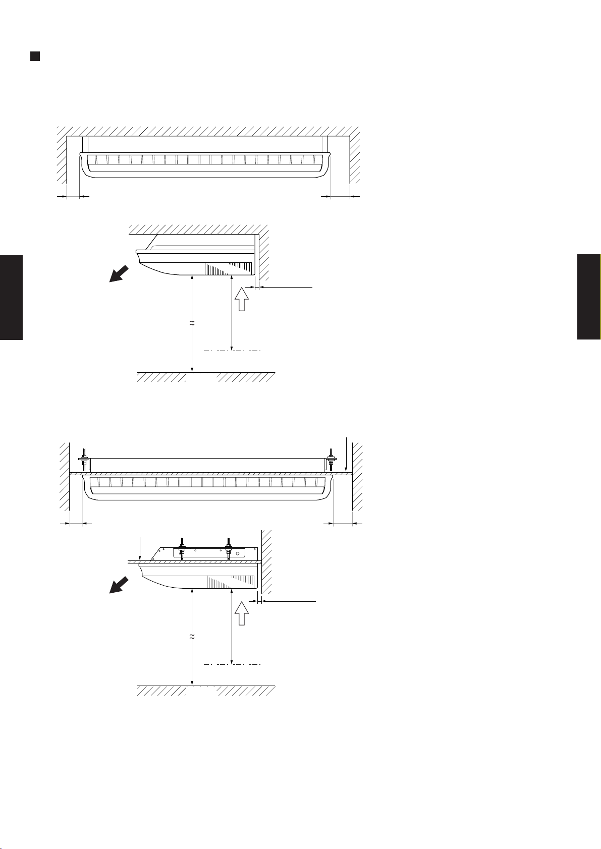
MOUNTING POSITION
Ceiling
INDOOR UNIT
(Unit : mm)
CEILING TYPE AB30-36
80 or over 150 or over
Ceiling
10 or over
1000 or over
2300 or over
Obstruction
Floor
Ceiling panel
INDOOR UNIT
CEILING TYPE AB30-36
80 or over 150 or over
Ceiling panel
10 or over
1000 or over
2300 or over
Obstruction
Floor
- (04 - 09) -
Page 11
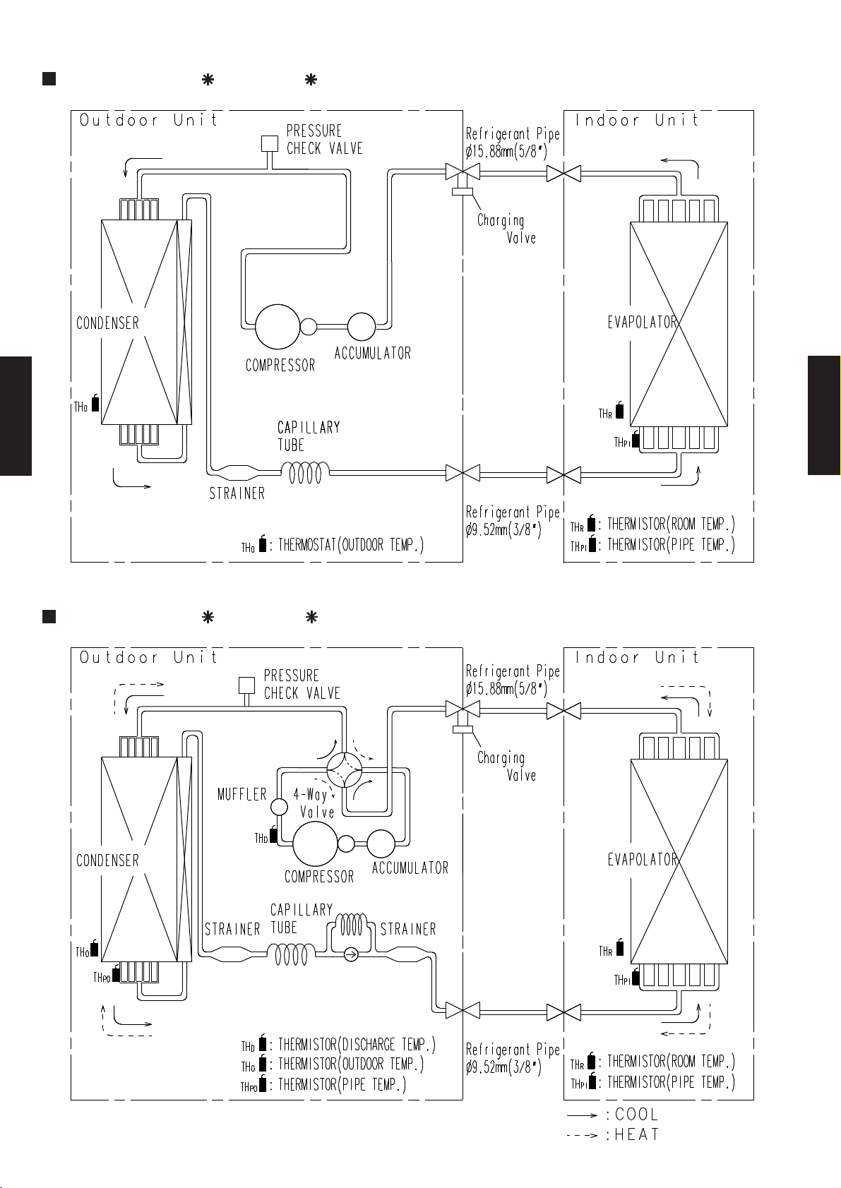
4-5. REFRIGERANT CIRCUIT
MODELS : AB 30F / AO 30F
CEILING TYPE AB30-36
CEILING TYPE AB30-36
MODELS : AB 30U / AO 30U
- (04 - 10) -
Page 12
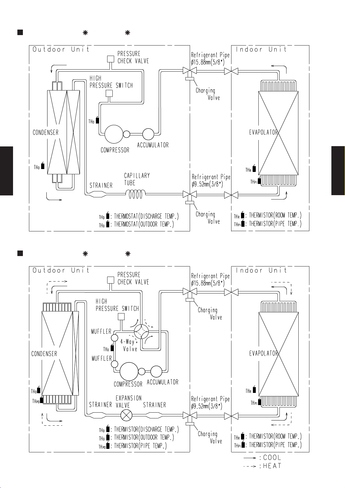
MODELS : AB 36F / AO 36F
CEILING TYPE AB30-36
CEILING TYPE AB30-36
MODELS : AB 36U / AO 36U
- (04 - 11) -
Page 13
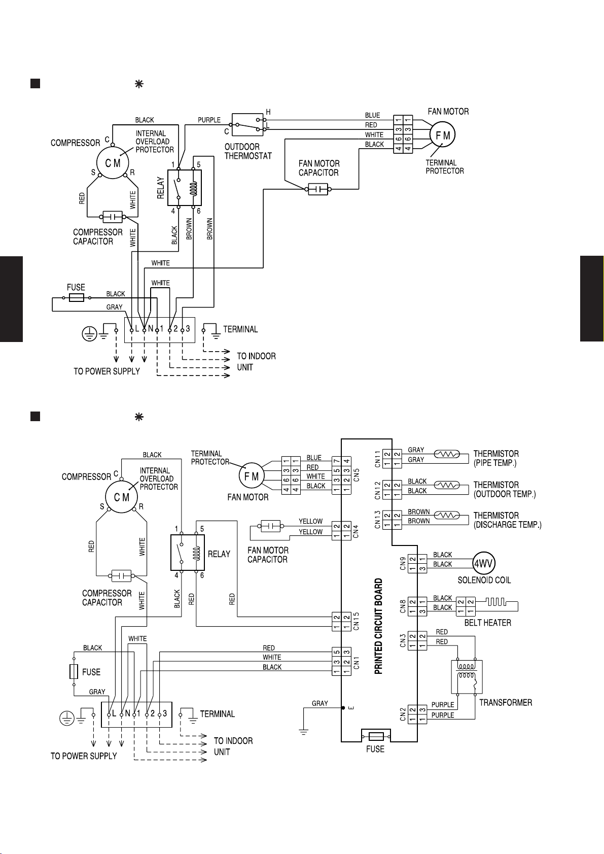
4-6. WIRING DIAGRAMS
4-6-1. OUTDOOR UNIT
MODEL : AO 30F
CEILING TYPE AB30-36
CEILING TYPE AB30-36
MODEL : AO 30U
- (04 - 12) -
Page 14

MODEL : AO 36F
CEILING TYPE AB30-36
CEILING TYPE AB30-36
230V 50Hz
3N 400V 50Hz
MODEL : AO 36U
3N 400V 50Hz
230V 50Hz
- (04 - 13) -
Page 15

4-6-2. INDOOR UNIT
MODELS : AB 30F, AB 36F
CEILING TYPE AB30-36
CEILING TYPE AB30-36
TO OUTDOOR UNIT
- (04 - 14) -
Page 16

MODELS : AB 30U, AB 36U
CEILING TYPE AB30-36
CEILING TYPE AB30-36
TO OUTDOOR UNIT
- (04 - 15) -
Page 17

4-7. CAPACITY TABLE
(°CDB)
19 °CWB
26 °CDB
32 °CDB
23 °CWB
27 °CDB
30 °CDB
21 °CWB
16 °CWB
22 °CWB
23 °CDB
21 °CDB
15 °CWB
29 °CDB
Indoor temperature
18 °CWB
Outdoor temperature
18 °CDB
12 °CWB
MODELS : AB 30F / AO 30F
COOLING
AFR 24.2
TC SHC PI TC SHC PI TC SHC PI TC SHC PI TC SHC PI TC SHC PI TC SHC PI TC SHC PI
0 9.59 7.16 1.85 9.78 7.19 1.90 9.97 7.22 1.91 10.25 7.52 1.94 10.38 7.46 1.95 10.60 7.33 1.98 10.70 7.26 1.99 10.79 7.56 2.00
5 9.25 6.97 2.08 9.46 7.00 2.12 9.69 7.02 2.14 10.03 7.38 2.18 10.17 7.34 2.19 10.42 7.24 2.23 10.53 7.18 2.24 10.64 7.49 2.25
10 8.85 6.73 2.29 9.07 6.75 2.34 9.29 6.80 2.37 9.67 7.19 2.41 9.82 7.16 2.43 10.08 7.08 2.47 10.20 7.03 2.49 10.32 7.35 2.51
15 8.44 6.49 2.51 8.64 6.53 2.57 8.86 6.57 2.60 9.21 6.96 2.65 9.36 6.94 2.67 9.63 6.87 2.72 9.75 6.83 2.74 9.86 7.16 2.76
20 8.41 6.27 2.75 8.59 6.30 2.80 8.80 6.34 2.83 9.13 6.72 2.88 9.28 6.70 2.91 9.55 6.64 2.96 9.68 6.60 2.98 9.80 6.94 3.00
25 8.74 6.47 2.39 8.96 6.50 2.41 9.16 6.53 2.43 9.50 6.90 2.47 9.65 6.87 2.48 9.91 6.80 2.52 10.03 6.76 2.53 10.15 7.08 2.54
30 8.19 6.17 2.62 8.42 6.21 2.64 8.61 6.28 2.66 8.93 6.64 2.70 9.08 6.62 2.71 9.34 6.56 2.75 9.47 6.53 2.77 9.59 6.87 2.79
35 7.61 5.91 2.85 7.76 5.96 2.86 7.96 5.99 2.89 8.26 6.35 2.93 8.40 6.34 2.95 8.67 6.30 2.99 8.80 6.27 3.01 8.93 6.62 3.03
40 6.93 5.61 3.09 7.03 5.64 3.10 7.20 5.66 3.12 7.49 6.03 3.17 7.63 6.02 3.19 7.89 5.99 3.24 8.03 5.98 3.26 8.15 6.34 3.30
43 6.44 5.36 3.23 6.55 5.42 3.24 6.70 5.44 3.26 6.99 5.82 3.31 7.14 5.82 3.33 7.40 5.80 3.38 7.55 5.80 3.40 7.68 6.16 3.43
AFR: Air flow rate (m3/min)
TC : Total capacity (kW)
SHC: Sensible Heat capacity (kW)
PI : Power Input (kW)
CEILING TYPE AB30-36
CEILING TYPE AB30-36
- (04 - 16) -
Page 18

CEILING TYPE AB30-36
( °CDB)
( °CWB)
Outdoor temperature
16 °CDB
18 °CDB
20 °CDB
Indoor temperature
27 °CDB
30 °CDB
25 °CDB
23 °CDB
(°CDB)
Outdoor temperature
Indoor temperature
18 °CDB
21 °CDB
23 °CDB
26 °CDB
27 °CDB
29 °CDB
30 °CDB
32 °CDB
12 °CWB
15 °CWB
16 °CWB
18 °CWB
19 °CWB
21 °CWB
22 °CWB
23 °CWB
MODELS : AB 30U / AO 30U
COOLING
AFR 24.2
TC SHC PI TC SHC PI TC SHC PI TC SHC PI TC SHC PI T C SHC PI TC SHC PI TC SHC PI
0 9.59 7.16 1.85 9.78 7.19 1.90 9.97 7.22 1.91 10.25 7.52 1.94 10.38 7.46 1.95 10.60 7.33 1.98 10.70 7.26 1.99 10.79 7.56 2.00
5 9.25 6.97 2.08 9.46 7.00 2.12 9.69 7.02 2.14 10.03 7.38 2.18 10.17 7.34 2.19 10.42 7.24 2.23 10.53 7.18 2.24 10.64 7.49 2.25
10 8.85 6.73 2.29 9.07 6.75 2.34 9.29 6.80 2.37 9.67 7.19 2.41 9.82 7.16 2.43 10.08 7.08 2.47 10.20 7.03 2.49 10.32 7.35 2.51
15 8.44 6.49 2.51 8.64 6.53 2.57 8.86 6.57 2.60 9.21 6.96 2.65 9.36 6.94 2.67 9.63 6.87 2.72 9.75 6.83 2.74 9.86 7.16 2.76
20 8.41 6.27 2.75 8.59 6.30 2.80 8.80 6.34 2.83 9.13 6.72 2.88 9.28 6.70 2.91 9.55 6.64 2.96 9.68 6.60 2.98 9.80 6.94 3.00
25 8.74 6.47 2.39 8.96 6.50 2.41 9.16 6.53 2.43 9.50 6.90 2.47 9.65 6.87 2.48 9.91 6.80 2.52 10.03 6.76 2.53 10.15 7.08 2.54
30 8.19 6.17 2.62 8.42 6.21 2.64 8.61 6.28 2.66 8.93 6.64 2.70 9.08 6.62 2.71 9.34 6.56 2.75 9.47 6.53 2.77 9.59 6.87 2.79
35 7.61 5.91 2.85 7.76 5.96 2.86 7.96 5.99 2.89 8.26 6.35 2.93 8.40 6.34 2.95 8.67 6.30 2.99 8.80 6.27 3.01 8.93 6.62 3.03
40 6.93 5.61 3.09 7.03 5.64 3.10 7.20 5.66 3.12 7.49 6.03 3.17 7.63 6.02 3.19 7.89 5.99 3.24 8.03 5.98 3.26 8.15 6.34 3.30
43 6.44 5.36 3.23 6.55 5.42 3.24 6.70 5.44 3.26 6.99 5.82 3.31 7.14 5.82 3.33 7.40 5.80 3.38 7.55 5.80 3.40 7.68 6.16 3.43
HEATING
AFR 24.2
CEILING TYPE AB30-36
-7 -9 6.18 2.10 6.08 2.17 5.89 2.24 5.70 2.30 5.61 2.34 5.42 2.40 5.23 2.44
-4 -6 6.75 2.27 6.65 2.34 6.46 2.40 6.27 2.47 6.18 2.50 5.99 2.57 5.80 2.60
1 -1 7.60 2.57 7.51 2.64 7.32 2.70 7.13 2.77 7.03 2.80 6.84 2.87 6.65 2.90
5 3 9.31 2.64 9.22 2.69 9.03 2.75 8.84 2.81 8.74 2.84 8.55 2.89 8.36 2.92
7 6 9.79 2.67 9.69 2.72 9.50 2.78 9.31 2.84 9.22 2.86 9.03 2.92 8.84 2.95
12 10 10.45 2.86 10.36 2.92 10.17 2.97 9.98 3.03 9.88 3.06 9.69 3.11 9.50 3.14
15 13 10.55 2.97 10.45 3.03 10.26 3.09 10.07 3.14 9.98 3.17 9.79 3.22 9.60 3.25
20 15 9.79 2.67 9.69 2.72 9.50 2.78 9.31 2.84 9.22 2.86 9.03 2.92 8.84 2.95
24 17 9.22 2.50 9.12 2.56 8.93 2.61 8.74 2.67 8.65 2.70 8.46 2.75 8.27 2.78
AFR: Air flow rate (m3/min)
TC : Total capacity (kW)
SHC: Sensible Heat capacity (kW)
PI : Power Input (kW)
TC PI TC PI TC PI TC PI TC PI TC PI TC PI
- (04 - 17) -
Page 19

MODELS : AB 36F / AO 36F
(°CDB)
Indoor temperature
18 °CDB
21 °CDB
23 °CDB
26 °CDB
27 °CDB
29 °CDB
30 °CDB
Outdoor temperature
32 °CDB
12 °CWB
15 °CWB
16 °CWB
18 °CWB
19 °CWB
21 °CWB
22 °CWB
23 °CWB
COOLING
AFR 27.7
TC SHC PI TC SHC PI TC SHC PI TC SHC PI TC SHC PI T C SHC PI TC SHC PI TC SHC PI
0 11.99 8.76 2.34 12.22 8.79 2.41 12.46 8.83 2.43 12.82 9.20 2.46 12.97 9.13 2.48 13.25 8.97 2.51 13.37 8.88 2.52 13.49 9.25 2.53
5 11.56 8.52 2.63 11.83 8.56 2.68 12.11 8.59 2.71 12.54 9.03 2.76 12.71 8.98 2.78 13.03 8.85 2.82 13.17 8.78 2.84 13.30 9.16 2.86
10 11.07 8.23 2.90 11.34 8.25 2.97 11.62 8.31 3.00 12.09 8.79 3.06 12.28 8.76 3.08 12.60 8.65 3.13 12.75 8.59 3.16 12.89 8.98 3.18
15 10.55 7.94 3.18 10.80 7.98 3.25 11.08 8.04 3.29 11.52 8.52 3.36 11.70 8.49 3.39 12.03 8.40 3.44 12.19 8.36 3.47 12.33 8.76 3.49
20 10.51 7.67 3.49 10.74 7.71 3.55 11.00 7.75 3.59 11.42 8.21 3.66 11.60 8.19 3.69 11.94 8.12 3.75 12.10 8.08 3.78 12.25 8.48 3.81
25 10.93 7.91 3.02 11.20 7.94 3.06 11.45 7.99 3.08 11.88 8.44 3.13 12.06 8.40 3.15 12.39 8.31 3.19 12.54 8.26 3.21 12.68 8.66 3.23
30 10.23 7.55 3.32 10.52 7.59 3.34 10.76 7.68 3.37 11.17 8.12 3.42 11.35 8.10 3.44 11.68 8.03 3.49 11.84 7.99 3.51 11.99 8.40 3.53
35 9.52 7.23 3.61 9.70 7.28 3.63 9.95 7.33 3.66 10.32 7.77 3.71 10.50 7.75 3.74 10.84 7.70 3.79 11.00 7.67 3.81 11.16 8.10 3.84
40 8.66 6.86 3.92 8.79 6.90 3.93 9.00 6.92 3.96 9.36 7.37 4.02 9.54 7.36 4.04 9.87 7.33 4.10 10.03 7.31 4.13 10.19 7.75 4.19
43 8.05 6.55 4.10 8.19 6.63 4.11 8.38 6.66 4.14 8.74 7.12 4.19 8.92 7.12 4.22 9.25 7.10 4.29 9.43 7.09 4.31 9.60 7.54 4.34
AFR: Air flow rate (m3/min)
TC : Total capacity (kW)
SHC: Sensible Heat capacity (kW)
PI : Power Input (kW)
CEILING TYPE AB30-36
CEILING TYPE AB30-36
- (04 - 18) -
Page 20

CEILING TYPE AB30-36
(°CDB)
16 °CWB
22 °CWB
Outdoor temperature
18 °CDB
12 °CWB
29 °CDB
Indoor temperature
32 °CDB
23 °CWB
23 °CDB
21 °CDB
15 °CWB
21 °CWB
27 °CDB
30 °CDB
18 °CWB
19 °CWB
26 °CDB
( °CDB)
( °CWB)
Outdoor temperature
27 °CDB
25 °CDB
23 °CDB
16 °CDB
18 °CDB
20 °CDB
Indoor temperature
30 °CDB
MODELS : AB 36U / AO 36U
COOLING
AFR 27.7
TC SHC PI TC SHC PI TC SHC PI TC SHC PI TC SHC PI T C SHC PI TC SHC PI TC SHC PI
0 11.07 7.80 2.63 11.37 7.84 2.67 11.57 7.88 2.70 12.07 8.32 2.78 12.27 8.32 2.78 12.57 8.24 2.85 12.77 8.17 2.85 12.87 8.54 2.89
5 10.57 7.51 2.89 10.77 7.58 2.96 11.07 7.66 2.96 11.47 8.10 3.03 11.67 8.10 3.07 12.07 7.95 3.11 12.17 7.95 3.14 12.37 8.32 3.18
10 10.50 7.67 2.99 10.71 7.71 3.06 11.03 7.75 3.10 11.45 8.21 3.17 11.55 8.21 3.17 11.97 8.14 3.24 12.08 8.06 3.27 12.29 8.45 3.27
15 11.10 7.94 2.74 11.37 7.98 2.80 11.66 8.04 2.84 12.12 8.52 2.89 12.32 8.49 2.92 12.66 8.40 2.97 12.83 8.36 2.99 12.98 8.76 3.01
20 10.51 7.67 3.01 10.74 7.71 3.06 11.00 7.75 3.09 11.42 8.21 3.15 11.60 8.19 3.18 11.94 8.12 3.23 12.10 8.08 3.26 12.25 8.48 3.28
25 10.93 7.91 2.81 11.20 7.94 2.84 11.45 7.99 2.87 11.88 8.44 2.91 12.06 8.40 2.93 12.39 8.31 2.97 12.54 8.26 2.98 12.68 8.66 3.00
30 10.23 7.55 3.09 10.52 7.59 3.11 10.76 7.68 3.13 11.17 8.12 3.18 11.35 8.10 3.20 11.68 8.03 3.25 11.84 7.99 3.27 11.99 8.40 3.29
35 9.52 7.23 3.36 9.70 7.28 3.38 9.95 7.33 3.41 10.32 7.77 3.46 10.50 7.75 3.48 10.84 7.70 3.53 11.00 7.67 3.55 11.16 8.10 3.57
40 8.66 6.86 3.65 8.79 6.90 3.66 9.00 6.92 3.68 9.36 7.37 3.74 9.54 7.36 3.76 9.87 7.33 3.82 10.03 7.31 3.84 10.19 7.75 3.89
43 8.05 6.55 3.81 8.19 6.63 3.82 8.38 6.66 3.85 8.74 7.12 3.90 8.92 7.12 3.93 9.25 7.10 3.99 9.43 7.09 4.01 9.60 7.54 4.04
HEATING
AFR 27.7
CEILING TYPE AB30-36
-10 -11 6.75 2.60 6.65 2.69 6.44 2.77 6.23 2.85 6.13 2.89 5.92 2.98 5.71 3.02
-7 -9 7.67 2.80 7.55 2.89 7.32 2.98 7.08 3.07 6.96 3.12 6.73 3.20 6.49 3.25
-4 -6 8.38 3.03 8.26 3.12 8.02 3.20 7.79 3.29 7.67 3.34 7.43 3.43 7.20 3.47
1 -1 9.44 3.13 9.32 3.22 9.09 3.30 8.85 3.38 8.73 3.42 8.50 3.50 8.26 3.54
5 3 11.56 3.21 11.45 3.28 11.21 3.35 10.97 3.42 10.86 3.45 10.62 3.52 10.38 3.55
7 6 12.15 3.31 12.04 3.38 11.80 3.45 11.56 3.52 11.45 3.55 11.21 3.62 10.97 3.66
12 10 12.98 3.55 12.86 3.62 12.63 3.69 12.39 3.76 12.27 3.80 12.04 3.86 11.80 3.90
15 13 13.10 3.69 12.98 3.76 12.74 3.83 12.51 3.90 12.39 3.93 12.15 4.00 11.92 4.04
20 15 12.15 3.31 12.04 3.38 11.80 3.45 11.56 3.52 11.45 3.55 11.21 3.62 10.97 3.66
24 17 11.45 3.11 11.33 3.17 11.09 3.24 10.86 3.31 10.74 3.35 10.50 3.42 10.27 3.45
AFR: Air flow rate (m3/min)
TC : Total capacity (kW)
SHC: Sensible Heat capacity (kW)
PI : Power Input (kW)
TC PI TC PI TC PI TC PI TC PI TC PI TC PI
- (04 - 19) -
Page 21

4-8. CAPACITY COMPENSATION FOR PIPE LENGTH
5 7.5 10 15 20 25 30
15 - - - 0.952 0.919 0.888 0.857
10 - - 0.985 0.952 0.919 0.888 0.857
7.5 - 1.000 0.985 0.952 0.919 0.888 0.857
5 1.010 1.000 0.985 0.952 0.919 0.888 0.857
0 1.010 1.000 0.985 0.952 0.919 0.888 0.857
-5 1.002 0.992 0.977 0.944 0.912 0.881 0.850
-7.5 - 0.988 0.973 0.941 0.908 0.877 0.847
-10 - - 0.969 0.937 0.904 0.874 0.843
-15 - - - 0.929 0.897 0.867 0.836
PIPE LENGTH (m)
COOLING
HEIGHT DIFFERENCE (m)
Outdoor unit
is up-side
Outdoor unit is
bottom-side
AND HEIGHT DIFFERENCE
MODELS : AB 30F / AO 30F
COEFFICIENT OF COMPENSATION FOR HEIGHT DIFFERENCE
CEILING TYPE AB30-36
CEILING TYPE AB30-36
- (04 - 20) -
Page 22

MODELS : AB 30U / AO 30U
PIPE LENGTH (m)
Outdoor unit is
bottom-side
Outdoor unit
is up-side
COOLING
HEIGHT DIFFERENCE (m)
HEIGHT DIFFERENCE (m)
PIPE LENGTH (m)
HEATING
Outdoor unit
is up-side
Outdoor unit is
bottom-side
COEFFICIENT OF COMPENSATION FOR HEIGHT DIFFERENCE
5 7.5 10 15 20 25 30
15 - - - 0.952 0.919 0.888 0.857
10 - - 0.985 0.952 0.919 0.888 0.857
7.5 - 1.000 0.985 0.952 0.919 0.888 0.857
5 1.010 1.000 0.985 0.952 0.919 0.888 0.857
0 1.010 1.000 0.985 0.952 0.919 0.888 0.857
-5 1.002 0.992 0.977 0.944 0.912 0.881 0.850
-7.5 - 0.988 0.973 0.941 0.908 0.877 0.847
-10 - - 0.969 0.937 0.904 0.874 0.843
-15 - - - 0.929 0.897 0.867 0.836
CEILING TYPE AB30-36
5 7.5 10 15 20 25 30
15 - - - 0.956 0.939 0.922 0.904
10 - - 0.979 0.961 0.943 0.927 0.909
7.5 - 0.993 0.982 0.964 0.946 0.929 0.911
5 1.005 0.995 0.984 0.966 0.948 0.931 0.913
0 1.010 1.000 0.989 0.971 0.953 0.936 0.918
-5 1.010 1.000 0.989 0.971 0.953 0.936 0.918
-7.5 - 1.000 0.989 0.971 0.953 0.936 0.918
-10 - - 0.989 0.971 0.953 0.936 0.918
-15 - - - 0.971 0.953 0.936 0.918
CEILING TYPE AB30-36
- (04 - 21) -
Page 23

MODELS : AB 36F / AO 36F
5 7.5 10 20 30 40 50
30 - - - - 0.857 0.823 0.788
25 - - - - 0.857 0.823 0.788
20 - - - 0.892 0.857 0.823 0.788
15 - - - 0.892 0.857 0.823 0.788
10 - - 0.964 0.892 0.857 0.823 0.788
7.5 - 1.000 0.964 0.892 0.857 0.823 0.788
5 1.010 1.000 0.964 0.892 0.857 0.823 0.788
0 1.010 1.000 0.964 0.892 0.857 0.823 0.788
-5 1.002 0.992 0.956 0.885 0.851 0.816 0.781
-7.5 - 0.988 0.953 0.882 0.847 0.813 0.778
-10 - - 0.949 0.878 0.844 0.809 0.775
-15 - - - 0.871 0.837 0.803 0.769
-20 - - - 0.864 0.830 0.796 0.763
-25 - - - - 0.823 0.790 0.756
-30 - - - - 0.816 0.783 0.750
COOLING
Outdoor unit
is up-side
Outdoor unit
is bottom-side
HEIGHT DIFFERENCE (m)
PIPE LENGTH (m)
COEFFICIENT OF COMPENSATION FOR HEIGHT DIFFERENCE
CEILING TYPE AB30-36
CEILING TYPE AB30-36
- (04 - 22) -
Page 24

MODELS : AB 36U / AO 36U
5 7.5 10 20 30 40 50
30 - - - - 0.893 0.867 0.840
25 - - - - 0.893 0.867 0.840
20 - - - 0.919 0.893 0.867 0.840
15 - - - 0.919 0.893 0.867 0.840
10 - - 0.985 0.919 0.893 0.867 0.840
7.5 - 1.000 0.985 0.919 0.893 0.867 0.840
5 1.014 1.000 0.985 0.919 0.893 0.867 0.840
0 1.014 1.000 0.985 0.919 0.893 0.867 0.840
-5 1.005 0.992 0.977 0.912 0.886 0.860 0.834
-7.5 - 0.988 0.973 0.908 0.882 0.856 0.830
-10 - - 0.969 0.905 0.879 0.853 0.827
-15 - - - 0.897 0.872 0.846 0.820
-20 - - - 0.890 0.864 0.839 0.814
-25 - - - - 0.857 0.832 0.807
-30 - - - - 0.850 0.825 0.800
Outdoor unit
is up-side
COOLING
Outdoor unit
is bottom-side
HEIGHT DIFFERENCE (m)
PIPE LENGTH (m)
5 7.5 10 20 30 40 50
30 - - - - 0.908 0.891 0.875
25 - - - - 0.913 0.896 0.879
20 - - - 0.934 0.917 0.901 0.884
15 - - - 0.939 0.922 0.905 0.888
10 - - 0.979 0.944 0.927 0.910 0.893
7.5 - 0.993 0.982 0.946 0.929 0.912 0.895
5 1.005 0.995 0.984 0.948 0.931 0.914 0.897
0 1.010 1.000 0.989 0.953 0.936 0.919 0.902
-5 1.010 1.000 0.989 0.953 0.936 0.919 0.902
-7.5 - 1.000 0.989 0.953 0.936 0.919 0.902
-10 - - 0.989 0.953 0.936 0.919 0.902
-15 - - - 0.953 0.936 0.919 0.902
-20 - - - 0.953 0.936 0.919 0.902
-25 - - - - 0.936 0.919 0.902
-30 - - - - 0.936 0.919 0.902
HEIGHT DIFFERENCE (m)
HEATING
PIPE LENGTH (m)
Outdoor unit
is up-side
Outdoor unit
is bottom-side
COEFFICIENT OF COMPENSATION FOR HEIGHT DIFFERENCE
CEILING TYPE AB30-36
CEILING TYPE AB30-36
- (04 - 23) -
Page 25

4-9. ADDITIONAL CHARGE CALCULATION
R410A
2300
7.5 10 15 20 25 30 (MAX)
0 (Charge less)
20g/m
R410A
2300
7.5 10 15 20 25 30 (MAX)
0 (Charge less)
40g/m
REFRIGERANT TYPE
R410A
2000
20 30 40 50 (MAX)
0 (Charge less)
30g/m
REFRIGERANT TYPE
R410A
3200
20 30 40 50 (MAX)
0 (Charge less)
30g/m
MODELS : AB 30F / AO 30F
REFRIGERANT TYPE
REFRIGERANT AMOUNT g
REFRIGERANT CHARGE
PIPE LENGTH m
CEILING TYPE AB30-36
ADDITIONAL CHARGE g
MODELS : AB 30U / AO 30U
REFRIGERANT TYPE
REFRIGERANT AMOUNT g
REFRIGERANT CHARGE
PIPE LENGTH m
ADDITIONAL CHARGE g
MODELS : AB 36F / AO 36F
REFRIGERANT AMOUNT g
+50 +150 +250 +350 +450
CEILING TYPE AB30-36
+100 +300 +500 +700 +900
REFRIGERANT CHARGE
PIPE LENGTH m
ADDITIONAL CHARGE g
MODELS : AB 36U / AO 36U
REFRIGERANT AMOUNT g
REFRIGERANT CHARGE
PIPE LENGTH m
ADDITIONAL CHARGE g
+300 +600 +900
+300 +600 +900
- (04 - 24) -
Page 26

4-10. OPERATION RANGE
AB 30F
AB 36F
AO 30F
AO 36F
Cooling
Dry
Cooling
Dry
Heating 16 to 30 °C - -7 to 24 °C
Cooling
Dry
Heating 16 to 30 °C - -10 to 24 °C
AO 30U
Model
Operation Range
AB 36U
AO 36U
Model
Operation Range
Model
Operation Range
AB 30U
Indoor unit Outdoor unit Mode Indoor unit Indoor humidity Outdoor unit
Indoor unit Outdoor unit Mode Indoor unit Indoor humidity Outdoor unit
Indoor unit Outdoor unit Mode Indoor unit Indoor humidity Outdoor unit
18 to 32 °C About 80% or less 0 to 43 °C
18 to 32 °C About 80% or less 0 to 43 °C
18 to 32 °C About 80% or less 0 to 43 °C
CEILING TYPE AB30-36
CEILING TYPE AB30-36
- (04 - 25) -
Page 27

4-11. FAN PERFORMANCE AND AIR FLOW
4-11-1. AIR VELOCITY DISTRIBUTION
MODELS : AB 30F, AB 30U
CEILING TYPE AB30-36
(m)
Unit : m/s
4
3
2
1
0
2 1 0.5 0.25
1
2
3
4
0 1 2 3 4 5 6 7 8 9 10 11 12 13 14 15 16 17 18
TOP VIEW
VERTICAL : UP
HORIZONTAL : CENTER
(m)
Unit : m/s
4
3
2
1
0
1
1
2
1
2
0.5
0.5
0.25
0.25
3
4
0 1 2 3 4 5 6 7 8 9 10 11 12 13 14 15 16 17 18
TOP VIEW
VERTICAL : UP
HORIZONTAL : RIGHT AND LEFT
(m)
(m)
Note :
Condition
Fan speed : High
Operation mode :FAN
(m)
Unit : m/s
3
2
2
1
0
0 1 2 3 4 5 6 7 8 9 10 11 12 13 14
(m)
1
0.25
0.5
SIDE VIEW
FLAP : CENTER
HORIZONTAL : CENTER
Unit : m/s
3
2
2
CEILING TYPE AB30-36
(m)
3
(m)
2
1
0.5
0.25
Unit : m/s
2
1
0
0 1 2 3 4 5 6 7 8 9 10 11 12 13 14 15 16 17 18
SIDE VIEW
FLAP : UP
HORIZONTAL : CENTER
(m)
1
1
0.5
0.25
0
0 1 2 3 4 5 6 7 8 9 10 11 12 13 14
SIDE VIEW
FLAP : DOWN
HORIZONTAL : CENTER
(m)
- (04 - 26) -
Page 28

MODELS : AB 36F, AB 36U
CEILING TYPE AB30-36
(m)
Unit : m/s
4
3
2
1
0
2 1 0.5 0.25
1
2
3
4
0 1 2 3 4 5 6 7 8 9 10 11 12 13 14 15 16 17 18
TOP VIEW
VERTICAL : UP
HORIZONTAL : CENTER
(m)
Unit : m/s
4
3
2
1
0
2
1
1
1
2
0.5
0.5
0.25
0.25
3
4
0 1 2 3 4 5 6 7 8 9 10 11 12 13 14 15 16 17 18
TOP VIEW
VERTICAL : UP
HORIZONTAL : RIGHT AND LEFT
(m)
(m)
Note :
Condition
Fan speed : High
Operation mode :FAN
(m)
Unit : m/s
3
2
2
1
0
0 1 2 3 4 5 6 7 8 9 10 11 12 13 14
(m)
1
0.25
0.5
SIDE VIEW
FLAP : CENTER
HORIZONTAL : CENTER
Unit : m/s
3
2
2
CEILING TYPE AB30-36
(m)
(m)
3
21
0.5
Unit : m/s
0.25
2
1
0
0 1 2 3 4 5 6 7 8 9 10 11 12 13 14 15 16 17 18
SIDE VIEW
FLAP : UP
HORIZONTAL : CENTER
(m)
1
1
0.25
0.5
0
0 1 2 3 4 5 6 7 8 9 10 11 12 13 14
SIDE VIEW
FLAP : DOWN
HORIZONTAL : CENTER
(m)
- (04 - 27) -
Page 29

4-11-2. AIR FLOW
m3/h
1450
l/s 403
CFM 853
m3/h
1280
l/s 356
CFM 753
m3/h
980
l/s 272
CFM 577
m3/h
3300
l/s 917
CFM 1942
m3/h
1600
l/s 444
CFM 942
780
LOW
400
850
750
600
LOW
Indoor unit
Outdoor unit
HIGH
MED
HIGH
FAN SPEED
NUMBER OF
ROTATIONS
(r.p.m)
AIR FLOW
MODELS : AB 30F / AO 30F, AB 30U / AO 30U
CEILING TYPE AB30-36
CEILING TYPE AB30-36
- (04 - 28) -
Page 30

MODELS : AB 36F / AO 36F
m3/h
1660
m3/h
1500
m3/h
1270
Indoor unit
MED
LOW
1000
900
750
AIR FLOW
NUMBER OF
ROTATIONS
(r.p.m)
FAN SPEED
HIGH
Outdoor unit
HIGH
CFM
Lower fan
4120
Upper fan
780
m3/h
7000
l/s
1944
780
m3/h
1660
m3/h
1500
m3/h
1270
750
HIGH
MED
LOW
FAN SPEED
NUMBER OF
ROTATIONS
(r.p.m)
AIR FLOW
1000
900
Outdoor unit
HIGH
Upper fan
Lower fan
Indoor unit
780
m3/h
6100
l/s
1694
780
CFM
3590
l/s 461
CFM 977
l/s 417
CFM 883
l/s 353
CFM 747
CEILING TYPE AB30-36
CEILING TYPE AB30-36
MODELS : AB 36U / AO 36U
l/s 461
CFM 977
l/s 417
CFM 883
l/s 353
- (04 - 29) -
CFM 747
Page 31

4-11-3. FRESH AIR
FRESH AIR CHARACTERISTIC
(Pa)
98
49
(mmAq)
10
8
6
CEILING TYPE AB30-36
36
4
CEILING TYPE AB30-36
30
2
INTAKE DUCT STATIC PRESSURE
0
0 1 2 3 4 5 6 7
FRESH AIR FLOW (m /min)
3
- (04 - 30) -
Page 32

4-12. NOISE LEVEL CURVE
4-12-1. OUTDOOR UNIT
COOLING
CEILING TYPE AB30-36
MODELS : AO 30F, AO 30U
80
70
60
50
40
30
20
Octave band sound pressure level, dB:(0dB=0.0002µbar)
10
0
63 125 250 500 1,000 2,000 4,000 8,000
Octave band center frequency,Hz
NC-65
NC-60
NC-55
NC-50
NC-45
NC-40
NC-35
NC-30
NC-25
NC-20
NC-15
MODELS : AO 36F, AO 36U
80
70
60
50
40
30
20
Octave band sound pressure level, dB:(0dB=0.0002µbar)
10
0
63 125 250 500 1,000 2,000 4,000 8,000
Octave band center frequency,Hz
NC-65
NC-60
NC-55
NC-50
NC-45
NC-40
NC-35
NC-30
NC-25
NC-20
NC-15
CEILING TYPE AB30-36
HEATING
MODEL : AO 30U MODEL : AO 36U
80
70
NC-65
60
50
40
30
20
Octave band sound pressure level, dB:(0dB=0.0002µbar)
10
NC-60
NC-55
NC-50
NC-45
NC-40
NC-35
NC-30
NC-25
NC-20
NC-15
80
70
60
50
40
30
20
Octave band sound pressure level, dB:(0dB=0.0002µbar)
10
NC-65
NC-60
NC-55
NC-50
NC-45
NC-40
NC-35
NC-30
NC-25
NC-20
NC-15
0
63 125 250 500 1,000 2,000 4,000 8,000 63 125 250 500 1,000 2,000 4,000 8,000
Octave band center frequency,Hz Octave band center frequency,Hz
0
- (04 - 31) -
Page 33

SOUND LEVEL CHECK POINT
MODELS : AO 30F, AO 30U
CEILING TYPE AB30-36
CEILING TYPE AB30-36
- (04 - 32) -
Page 34

MODELS : AO 36F, AO 36U
CEILING TYPE AB30-36
CEILING TYPE AB30-36
- (04 - 33) -
Page 35

4-12-2. INDOOR UNIT
HIGH
LOW
HIGH
LOW
HIGH
LOW
HIGH
LOW
COOLING
CEILING TYPE AB30-36
MODELS : AB 30F, AB 30U
80
70
NC-65
60
50
40
30
20
Octave band sound pressure level, dB:(0dB=0.0002µbar)
10
0
63 125 250 500 1,000 2,000 4,000 8,000
Octave band center frequency,Hz
NC-60
NC-55
NC-50
NC-45
NC-40
NC-35
NC-30
NC-25
NC-20
NC-15
MODELS : AB 36F, AB 36U
80
70
60
50
40
30
20
Octave band sound pressure level, dB:(0dB=0.0002µbar)
10
0
63 125 250 500 1,000 2,000 4,000 8,000
Octave band center frequency,Hz
NC-65
NC-60
NC-55
NC-50
NC-45
NC-40
NC-35
NC-30
NC-25
NC-20
NC-15
CEILING TYPE AB30-36
HEATING
MODEL : AB 30U MODEL : AB 36U
80
70
NC-65
60
50
40
30
20
Octave band sound pressure level, dB:(0dB=0.0002µbar)
10
NC-60
NC-55
NC-50
NC-45
NC-40
NC-35
NC-30
NC-25
NC-20
NC-15
80
70
60
50
40
30
20
Octave band sound pressure level, dB:(0dB=0.0002µbar)
10
NC-65
NC-60
NC-55
NC-50
NC-45
NC-40
NC-35
NC-30
NC-25
NC-20
NC-15
0
63 125 250 500 1,000 2,000 4,000 8,000 63 125 250 500 1,000 2,000 4,000 8,000
0
Octave band center frequency,Hz Octave band center frequency,Hz
- (04 - 34) -
Page 36

SOUND LEVEL CHECK POINT
UNDER CEILING
1m
1
MIC
1 0.8m (For AB12 AB24)
1m (For AB30 AB54)
CEILING TYPE AB30-36
CEILING TYPE AB30-36
- (04 - 35) -
Page 37

4-13. ELECTRIC CHARACTERISTICS
Main Fuse (Circuit
breaker) Current
mm
2
0.7 × 2
0.22
36(240V)
30
3.5303.5
1.0
0.140 × 2
0.140 × 2
0.7 × 2
1.0
21
AB 36F
AB 36U
AO 36F
AO 36U
3.5
96
96
0.22
36(240V)
0.7
0.20
0.140
0.9
Indoor unit
Outdoor unit
0.7
0.140
0.921230
50
AB 30F
20
3.5
AO 30F
AO 30U
3N 400
50
20
AB 30U
-
Outdoor Fan Motor
Indoor Fan Motor
0.20
Rated Value
Mode
*1) Wiring Spec
Power Supply
Model Name
Voltage V
Frequency Hz
Cooling Heating Cooling Heating Cooling Heating Cooling Heating
Current A 13.6 - 13.6 13.1 6.2 - 5.9 6.2
Input kW 2.95 - 2.95 2.78 3.74 - 3.48 3.45
Max Operating Current A 17.0 - 17.0 16.0 7.5 - 7.0 7.5
Starting Current A 70 - 70 70 37 - 37 37
A
Power Cable
*2)Limited wiring length m
Input kW
Full Load Amp. A
Input kW
Full Load Amp. A
Belt Heater W
CEILING TYPE AB30-36
*1) Wiring Spec : Selected Sample
(Selected based on Japan Electrotechnical Standard and Codes Committee E0005)
*2) Limited Wiring length : This is the wiring length in case voltage descent is less than 2%.
When the wiring length becomes long, please select the wiring of a more larger
CEILING TYPE AB30-36
- (04 - 36) -
Page 38

4-14. SAFETY DEVICE
MODEL NAME
PROTECTION FORM AO 30F AO 30U AO 36F AO 36U
FUSE
(SIDE OF SUPPLY TERMINAL)
-
FUSE ON PCB - - 3.15A 250V - 6.3A 250V
FAN MOTOR PROTECTOR THERMAL PROTECTOR
COMPRESSOR THERMAL PROTECTOR
HIGH PRESSURE PROTECTION
PRESSURE SWITCH - -
DISCHARGE THERMOSTAT THERMAL PROTECTOR - -
OFF:130±5°C
ON:100±15°C
-
5A 250V
150±5°C OFF
OFF : 25°C(78A) 120°C(29.6A)
ON : 90±10°C
OFF:4.2±0.1MPa
ON:3.2±0.15MPa
OFF : 25°C(28A) 120°C(8.1A)
ON : 80±10°C
MODEL NAME
PROTECTION FORM AB 30F AB 30U AB 36F AB 36U
PCB FUSE -
FAN MOTOR PROTECTOR THERMAL PROTECTOR
3.15A 250V
120±5°C OFF
OUTDOOR UNIT
INDOOR UNIT
CEILING TYPE AB30-36
CEILING TYPE AB30-36
- (04 - 37) -
Page 39

4-15. FUNCTION SETTING
Auto restart validity/invalidity
Room temperature correct coefficient
Room temperature correct coefficient
Forbidden
Remote control unit single code
Remote control unit single code
INDOOR UNIT
DIP SW
3
JM3
SW 1
Jumper Wire
JM1
JM212
4-15-1. INDOOR UNIT
SWITCH POSITION
Indoor unit control circuit board
CEILING TYPE AB30-36
CEILING TYPE AB30-36
JM1
JM3
JM2
CN10
- (04 - 38) -
Page 40

SW 1-1
SW state
OFF
Invalidity
ON
Validity
Jumper wire
JM3
Remote control unit signal code
connect
connect
A
JM2
Disconnect
Disconnect
Disconnect
connect
connectBC
D
Disconnect
4-15-2. SWITCH FUNCTION (INDOOR UNIT)
0 deg
0 deg
0 deg
cooling
-2 deg
SW 1-2
SW 1-3
0 deg
heating
dry
-2 deg
-2 degONONONOFF
OFF
+2 deg
-2 deg
OFF
SW state
-2 deg
OFF
ON
0 deg
+4 deg
DIP SWITCH SETTING
SW1-1. Auto restart setting
Auto restart function can be selected by turning this switch ON/OFF.
AUTO RESTART SETTING
( Factory setting)
SW1-2, 1-3. Room temperature correct coefficient of heating.
Decide the heating temperature correct coefficient vale of heating.
TEMPERATURE CORRECTION
( Factory setting)
CEILING TYPE AB30-36
CEILING TYPE AB30-36
JUMPER WIRE SETTING
JM 1, 2, 3 setting
( Factory setting)
- (04 - 39) -
Page 41

4-16. OPTIONAL PARTS
Drain water riser kit (UTR-DPB241)
Optional drain lift-up mechanism allows more flexible installation.
ROUND FLANGE (UTD - RF204)
Round flange is used when the fresh air duct is installed.
CEILING TYPE AB30-36
CEILING TYPE AB30-36
Round flange
- (04 - 40) -
 Loading...