

Page 1
POWER SYSTEMS, INC
Owner’s Manual
SUARDIAry
by GENERAC- POWER SYSTEMS
Liquid-cooied, Prepackaged
Standby Generators
Models:
04136- 0 (8 kW/Singie-phase)
04137- 0 (8 kW/Three-phase)
Page 2

INTRODUCTION
Thank you for purchasing the Guardian product
line by Generac Power Systems. This model is a
compact, high performance, liquid-cooled, enginedriven generator designed to automatically supply
electrical power to operate critical loads during a
utility power failure.
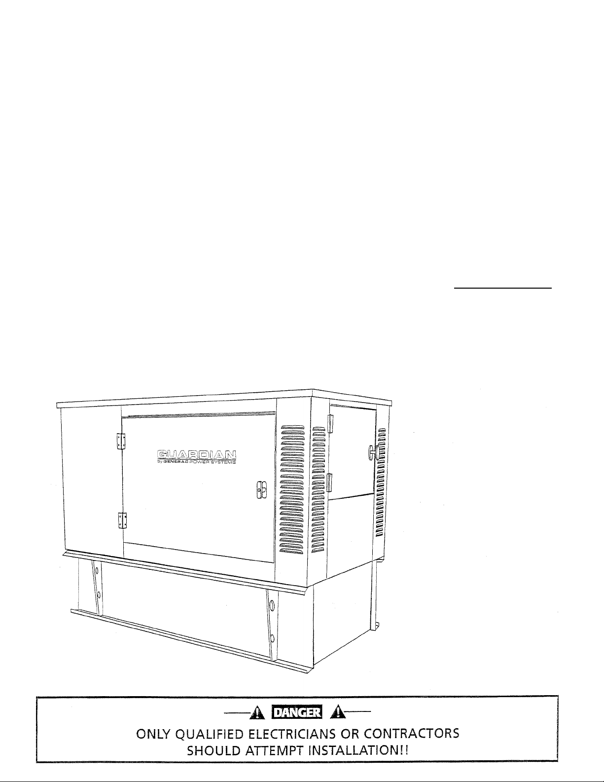
This unit is factory installed in an all-weather, metal
enclosure that is intended exclusively for outdoor
installation.
» READ THIS MANUAL THOROUGHLY
______________
If you do not understand any portion of this manual,
contact Generac or your nearest Generac/Guardian
Authorized Dealer for starting, operating and servic
ing procedures.
Throughout this publication, and on tags and
decals affixed to the generator, DANGER, WARNING,
CAUTION and NOTE blocks are used to alert you to
special instruction about a particular operation that
may be hazardous if performed incorrectly or care
lessly. Observe them carefully. Their definitions are
as follorvs;
-AEŒ3 A-
After this heading, you can read instructions that,
if not strictly complied with, wiil result in personal
injury or property damage.
—A WARNING A—
After this heading, you can read instructions that,
if not strictly complied with, may result in persona!
injury or property damage.
------
M CAUTION M
After this heading, you can read instructions that,
if not strictly complied with, could result in damage
to equipment and/or property.
NOTE:
After this heading, you can read explanatory
statements that require special emphasis.
These safety warnings cannot eliminate the hazards
that they indicate. Common sense and strict com
pliance with the special instructions whUe perform
ing the seiwice are essential to preventing accidents.
Four commonlv used safety symbols accompany
tire DANGER. WARNING and CAUTION blocks. The
type of information each indicates is as follows:
This symbol points out important safety informa
A
tion that, if not followed, could endanger persona!
safety and/or property of you and others.
This symbol points out potential explosion hazard.
This symbol points out potential fire hazard.
A This symbol points out potential electrical shock
hazard.
Generac® Power Systems, Inc.
-----------
,
The operator is responsible for proper and safe use
of the equipment. We strongly recommend that the
operator read this Owner’s Manual and thoroughly
understand all instructions before using this equip
ment. We also strongly recommend instructing
other users to properly start and operate the unit.
This prepares them if they need to operate the
equipment in an emergency.
# CONTENTS
________________ ______________________
This manual contains pertinent owner’s informa
tion, including warranty, electrical diagrams,
exploded views and lists of repair parts, for the fol
lowing Guardian models;
04136-0 and 04137-0
4 OPERATION AND MAINTENANCE_____________
_
It is the operator's responsibility to perform all safety
checks, to malce sure that all maintenance for sale
operation is performed promptly and to have the
equipment checked periodically by a Generac/
Guardian Authorized Dealer. Normal maintenance
service and replacement of maintenance parts are the
responsibility of the owner/operator and, as such,
are not considered defects in materials or workman
ship within the terms of the warranty. Indirfdual
operating habits and usage contribute to the need for
maintenance service.
Proper maintenance and care of your generator ensure
a ininimumi number of problems and keep operating
expenses at a rnlniaium. See your Generac/Guardian
Autiiorized Dealer for service aids and accessories.
^ HOW TO OBTAIN SERVICE_______________________
V.'Tien your generator requires servicing or repairs,
simply contact a Generac/Guardian Authorized
Dealer for assistance. Sendee technicians are facto
ry-trained and are capable of handling all of your
sendee needs.
WTien contacting a Generac/Guardian Autlrorized
Dealer or tlie factoiy about parts and service,
always supply the complete model number and
serial number of your unit as grfen on its data
decal, which is located on your generator.
Model No. Serial No.
AUTHORIZED
DEALER LOCATION
To locate the GENERAC/GUARDIAN AUTHORIZED
DEALER nearest you, please call this number:
1-800-747-1530
DEALER LOCATION INFORMdTION
CNN BE OBTAINED AT THIS NUMBER.
Page 3

SAFETY RULES
SAVE THESE INSTRUCTIONS - The manufacturer suggests that these rules for safe
operation be copied and posted in potential hazard areas. Safety should be stressed to all
A
operators and potential operators of this equipment. Mm.
important Safety instructions
Guardian Llquid-cooied 8 kW Generators
WARNING:
The engine exhaust from this product
contains chemicals known to the state
of California to cause cancer, birth
Study these SAf'ETY RULES carefully before
installing, operating or servicing this equipment.
Become familiar with this Oiuner's Manual and with
the unit. The generator can operate safely, effi
ciently and reliably only If it is properly installed,
operated and maintained. Many accidents are
caused by failing to follow simple and fundamental
rules or precautions.
Generac cannot possibly anticipate every possi
ble circumstance that might involve a hazard. The
warnings in this manual, and on tags and decals
afffxed to the unit are, therefore, not all-inclusive. If
you use a procedure, work method or operating
technique Generac does not specificaJly recom
mend, you must satisfy yourself that it is safe for
you and others. You also must make sure the pro
cedure. work method or operating technique that
you choose does not render the generator unsafe.
-A0UE33 A-
Despite the safe design of this ' generator,
A
operating this equipment imprudently, neglecting
its maintenance or being careless can cause
possible injury or death. Permit only responsible
and capable persons to operate or maintain this
equipment.
Potentially lethal voltages are generated by
A
these machines. Ensure ai! steps are taken to
render the machine safe before attempting to
work on the generator.
Parts of the generator are rotating and/or hot
during operation. Exercise care near running
generators.
M GEIMERAL HAZARDS M
For safety reasons, Generac recommends
that the installation, inihal start-up and mainte
nance of this equipment is carried out by a
Generac/Guardian Authorized Dealer.
The engine exhaust fumes contain carbon
monoxicTe, which can be DEADLY. This danger
ous gas, If breathed in sufficient concenhations,
can cause unconsciousness or even death. This
exliaust system must be installed properly, in
strict compliance with applicable codes and stan
dards. Following installation, you must do noth
ing that might render the system unsafe or in
noncompliance with such codes and standards.
Keep hands, feet, clothing, etc., away from drive
belts, fans, and other moving or hot parts. Never
remove any drive belt or fan guard while the unit
is operating.
Adequate, unobstructed flow of cooling and venti
lating air is critical to comect generator operation.
Do not alter the installation or permit even partial
blockage of ventilation provisions, as tliis can
seriously affect safe operation of the generator.
When working on this equipment, remain alert at
all times. Never work on the equipment when you
are physically or mentally fatigued.
Inspect the generator regularly, and repair or
replace all damaged or defective parts irrumedi-
ately. Always use factory-authorized parts.
Turn off the AC power to the batterv' charger
before disconnecting the battery to minimize the
chance of equipment damage.
Before performing any maintenance on the gen
erator, disconnect Its battery cables to prevent
accidental start-up. Disconnect the cable from
tlie battery post indicated by a NEGATIYTD. NEG
or H first. Reconnect that cable last.
Never use the generator or any of its parts as a
step. Stepping on the unit can stress and break
parts, and may result in dangerous operating
conditions from leaking etdaaust gases, fuel leak
age, oil leakage, etc.
Generac® Power Systems, Jnc.
Page 4

Table of Contents
Guardian Liquíd-cooied 8 kW Generators
Introduction
Read This Manual Thoroughly
Contents
Operation and Maintenance
....
....................inside Front Cover
.........................
...........................................................
..............................
IFC
IFC
IFC
How, to Obtain Service ....................................IFC
Authorized Dealer Locator Number
Safety Rules
.....
.................................................
..................
.......2
IFC
Section Ì - General Information..................................
1.1 Unpacking/Inspection
1.1.1 Lifting the Generator
1.2
The Generator .................................................4
1.3
Generator AC Connection Systems
Automatic System Operation
1.4
Main Circuit Breaker
1.5
Engine Protective Devices
1.6
....................................
.........................
................
.........................
......................................
..................1...........
1.6.1 Low Oil Pressure Switch....................5
1.6.2
1.6.3
1.6.4
1.6.5
Specifications
1.7
High Coolant
Temperature Switch
..........................
Low Coolant Level Switch ................6
Overspeed Shutdovm
Or’ercrank Shutdown
........................
........................
..................................................
1.7.1 Generator............................................6
1.7.2 Engine ................................................6
Fuel Requirements
1
and Recommendations
.............'..................
1.9 Engine Oil Recommendations.........................7
1.10 The Barterv .....................................................7
2.4 Automatic Transfer Operation
2.5 Sequence of Automatic Operation
.......................
..................
Q
9
2.6 Engine Heater................................................10
2.7 Weeldy Exercise Cycle .................................10
2.8 Optional GTS Transfer Switch .....................10
2.8.1 Using an Optional GTS
Transfer Switch
Section 3 - Maintenance
4
4
4
4
5
5
5
3.1 25-Hour Break-in Period
3.2 25-Hour Checkup
3.3 Checldng the Engine Oil Level
3.4 Changing the Engine Oil and Filter ..............12
3.5 Changing the Engine Air Cleaner
3.6 Вatteiy Maintenance
3.7 Cooling System
............................................
3.8 Overload Protection for
Engine DC Electrical System
................................
..........
.................................12
..............................
..........................................
....................
.................
.....................................
.......................
11
12
12
12
13
13
14
14
3.9 Fuse................................^...............................14
5
6
6
6
3.10 Engine Coolant
3.11 Miscellaneous Maintenance
3.11.1 Cleaning the Generator
3.11.2 Rodent Protection
3.12 Out of Sendee Procedure
3.12.1 Removal From Service
3.12.2 Return to Service
3.13 Service Schedule
..............................................
.........................
....................
.............................
...............................
.....................
.............................
..........................................
14
15
15
15
15
15
15
16
7
Section 4 - Troubleshooting
...........................17
4.1 Troubleshooting Guide.................................17
Section 2 - Operation
2.1 Control Console Components
2.1.1 AC Voltmeter
2.1.2 AC Ammeter
2.1.3 AC Frequency Meter
....
.................................8
.........................
.....................................
.......................................
..........................
2.1.4 DC Voltmeter .....................................8
2.1.5 Hourmeter
2.1.6 Auto/Off/Manual Switch
2.1.7 Fault Indicator Lamp
.........................................
...................
.........................
2.1.8 30-amp Fuse.......................................8
2.1.9 Voltage-phase Selector Switch
2.1.10 Set Exercise Time Switch
2.1.11 Main Circuit Breaker .........................8
2.2 Preparation Before Start-up
............................
2.3 Using the Auto/Off/Manual Switch
2.3.1 “Auto" Position
2.3.2 “Off Position
2.3.3 “Manual" Position
.................................
......................................
..............................
.............
.................
................
Section 5- Electrical Data................................18
S
8
8
Section 6 - Exploded Views and
Parts Lists.....................................................22
S
Section 7 - Installation Drawings
..................
34
S
8
Section 8 - Warranty
......................................
36
8
8
8
8
8
8
9
9
еЗепегас® Power Systems, ¡nc.
Page 5

/k
ELECTRICAL HAZARDS
Important Safety Instructions
Guardian Liquid-cooled 8 kW Generators
FIRE HAZARDS
SAFETY RULES
All generators covered by this manual produce
dangerous electrical voltages and can cause fatal
electrical shock. Utility power delivers extremely
high and dangerous voltages to the transfer
switch as does the standby generator when it is
in operation. Avoid contact with bare wires, ter
minals, connections, etc., while the unit is run
ning, Ensure all appropriate covers, guards and
barriers are in place before operating the genera
tor. If you must work around an operating unit,
stand on an insulated, diy surface to reduce
shock hazard.
Do not handle any kind of electrical device while
standing in water, while barefoot, or while hands
or feet'^are wet. DANGEROUS ELECTRICAX
SHOCK my RESULT.
The National Electrical Code (NEC) requires the
frame and emernal electrically conductive parts
of the generator to be connected to an approved
earth ground. Local electrical codes also may
require proper grounding of the generator electri
cal system.
ATter installing this standby electrical system, the
generator may crank and start at any time vdthout warning. Wlien this occurs, load circuits are
transferred to the STANDBY (generator] power
source. To prevent possible injury if such a start
and transfer occur, always set the generator’s
Auto/Off/Manual switch to its OFF position
before working on equipment.
In case of accident caused by electric shock,
immediately shut down the source of electrical
power. If this is not possible, attempt to free the
victim from the live conductor. AVOID DIRECT
CONTACT WITH THE VICTIM. Use a noncon
ducting implement, such as a rope or board, to
free the victim from the live conductor. If the vic
tim is unconscious, apply first aid and get imme
diate medical help.
Never wear jewelry when working on this equip
ment. Jewelry can conduct electricity resulting in
electric shock, or may get caught in moving com
ponents causing injun/.
For fire safety, the generator must be installed
and maintained properly. Installation altvays
must comply with applicable codes, standards,
laws and regulations. Adhere strictly to local,
state and national electrical and building codes.
Comply with regulations the Occupational Safety
and Health Administration (OSHA) has estab
lished. Also, ensure that the generator is
installed in accordance with the manufacturer's
instructions and recommendations. Following
proper installation, do nothing that might alter a
safe installation and render the unit in noncom
pliance mth the aforementioned codes, stan
dards, laws and regulations.
Keep a fire extinguisher near the generator at ail
times. Extinguishers rated JABC" by the National
Fire Protection Association are appropriate for
use on the standby electric system. Keep the
extinguisher properly charged and be familiar
with its use. If you have any question pertaining
to fire extinguishers, consult your local fire
department.
A
EXPLOSION HAZARDS
A
Do not smoke around the generator. Wipe up any
fuel or oil spills immediately. Ensure that no
combustible materials are left in the generator
compartment, or on or near the generator, as
FIRE' or EXPLOSION may result. Keep the area
surrounding tlie generator clean and free from
debris.
Although using diesel fuel is safer than using gaso
line or gaseous fluids, which are are extremely
EXPLOSIVE, diesel stiU. presents the danger of
possible FIRE. Install the fuel supply system
according to applicable fuel-gas codes. Before plac
ing the standby electric system into sertlce, fuel
system lines must be properly purged and lecJt
tested according to applicable code. After installa
tion, you must inspect the fuel system periodically
for leaks. No lealtage is permitted.
Generac® Power Systiems, inc.
Page 6
GENERAL
INFORMATION
Section 1 — General Information
Guardian Liquid-cooied 8 kW Generators
1,1 UNPACKlNG/iNSPECTiON
After unpacldng, carefully inspect the contents
for damage.
« This standby generator set has been factory
installed in an all-weather, metal enclosure that
is intended exclusively for outdoor installation.
-A WARNING A-
lf this generator is used to power electrical load
A
circuits normally powered by a utility power
source, you are required by code to install a
transfer switch. The transfer switch must effec
tively isolate the electrical system from the util
ity distribution system when the generator is
operating (NEC 701). Failure to isolate an elec
trical system by such means will result in dam
age to the generator and also may result in
injury or death to utility power workers due to
backfeed of electrical energy.
If. any loss or damage is noted at time of delivery,
have the person(s) making the delivery note all
damage on the freight bill or affix his or her signa
ture under the consignor's memo of loss or damage.
If you note loss or damage after delivery, separate
the damaged materials and contact the carrier for
claim procedures.
“Concealed damage” is understood to mean damage
to the contents of a package that is not in evidence
at the time of delivery, but is discovered later.
# 1.1.1 LIFTING THE GENERATOR
-A WARNING A-
When lifting or hoisting equipment is used, be
A
careful not to touch overhead power lines.
The generator's weight of more than 1,500
A
pounds requires proper tools and equipment,
and qualified personnel to be used in all phases
of handling and unpacking.
1.2 THE GENERATOR ..
This liquid-cooled, Guardian generator set is
designed to supply electrical power to operate criti
cal electrical loads during utility power failure. The
unit has a four-pole revolving field (rotor) and uti
lizes long-life brushes and slip rings to deliver exci
tation current to the rotor windings. The rotor is
directly connected to the engine shaft by a highstrength flexible disc. The engine governor holds
the diesel engine and rotor speeds at a constant
factory setting of approximately 1,860 rpm.
Use this generator as a source of electrical power
for tlie operation of 120- and/or 240-volt, singleor three-phase loads; or 120- and/or 208-volt,
three-phase loads.
These models are available, rated as follows;
04136- 0: Provides 8,000 watts (8 kW) of single
phase power.
04137- 0: Provides 8,000 rvatts (8 kVV) of three-
phase power.
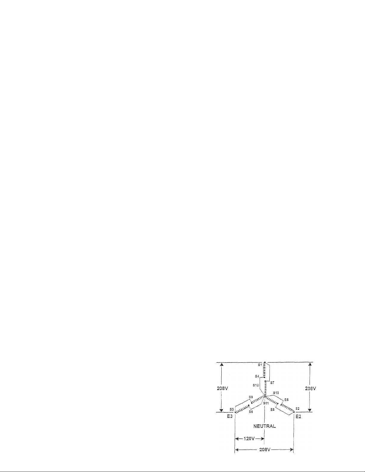
1.3 GENER.ATORAC
CONNECTION SYSTEMS
Ttie three-phase generators are shipped from tlie fac
tory with their stator AC output leads connected in a
12-lead low we configuration (Figure 1.1). This tyq)e
of connection system wül supply a 120- and/or 208volt, three-phase output as showm in tire illustration.
If, however, load voltage requires a 120/240-voIt,
single- or three-phase output, the stator's output
leads will need to be reconnected (Figure 1.2). This
task should be performed only by a qualified
Generac/Guardian Authorized Technician. Refer to
the
Guardian Installamn, Start-up and Adjustment
Manual (Part No, 79699) for details.
Figure 1.1 - 12-!ead Low Wye
Generator AC Connection System
E1
Page 7
Section 1 — Generai Information
Guardian Liquid-cooied 8 kW Generators
GENERAL
INFORMATION
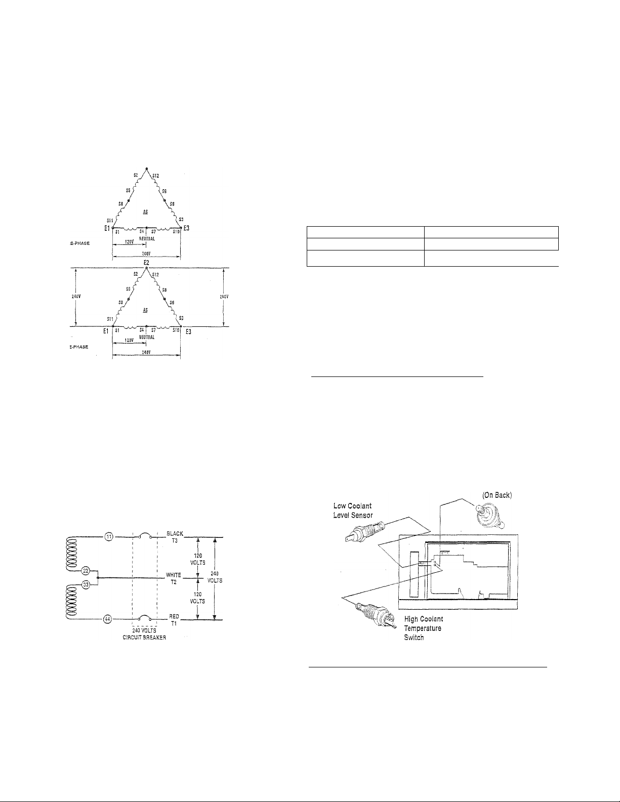
Figure 1.2 - Single- and Three-phase Delta
Generator AC Connection System
Figure 1.3 represents a single-phase, threenvlre
generator AC connection system. The stator assem
bly in this system consists of a pair of stationaiy
windings with Pan leads brought out of each wincl-
ing. Each single nhnding can supply a 120-volt, 60Hertz AC output. When the two windings are con
nected in series, a 240-volt, 60-Hertz AC output
results. Typically, the two "hot” leads in the circuit
are Wires 11 and 44. The neutral leads are the
junction of Wires 22 and 33.
Figure 1.3 - Single-phase
Generator AC Connection System
When utility source voltage has been restored, the
switch transfers back to the utility source voltage,
and the generator then shuts down,
1.5 MAIN CIRCUIT BREAKER
The generator’s main circuit breaker is included with
the unit as shipped from the factory. The breaker for
each unit is described as follows:
Mode! Number Circuit Breaker Ratinq
04135-0
04137-0 35A-3P-BQ3
35A-2P-BQ2
1.6 ENGINE PROTECTIVE DEVICES
The engine has several safely switches tliat cause
it to automatically shut down under the following con
ditions: low oil pressure, high coolant temperature,
low coolant level, and engine overspeed or overcrank.
See Figure 1.4 for the location of these devices.
4 1.6.1 LOW Oil PRESSURE SWITCH
This switch is normally closed {N.C.] but is held open
by engine oil pressure during engine running. Should
operating oU pressure drop below apprommately 15
psi, the switch contacts close, and die engine shuts
down automatically.
Figure 1.4 - Engine Protective Devices
________________
Low Oil
Pressure Switch
1.4 , AUTOMATIC SYSTEM OPERATION
Wnen this generator, along with its transfer switch,
has been Installed and interconnected, a circuit
board in the generator panel continuously monitors
utility power source voltage. Should that voltage
drop below a preset value, and remain at such a low
state for a preset amount of time, the generator
cranks and starts. After the generator starts, the
transfer switch transfers load circuits so the genera
tor can power them.
4 1.6.2 HIGH COOLANT TEMPERATURE SWITCH
This normally open (N.O.) thermostatic switch has
a sensing tip that is immersed in captive coolant.
Should the coolant temperature exceed approzdmately 124° C (256° F), the switch contacts close,
wTich causes the engine to shut clown automatically.
Generac® Power Systems, !nc.
Page 8

GENERAL
INFORMATION
Section 1 — General information
Guardian Liquid-cooied 8 kW Generators
» 1.6.3 LOW COOLANT LEVEL SWITCH
Should tlie .engine coolant level drop below tloe level
of’the high coolant temperature switch, it is possible
for the engine to overheat wltlaout automatic shut
down. To prevent such overheating without automat
ic shut down, the engine has a low coolant level sen
sor. If the engine coolant drops too low, the engine
_____________
_
# 1.6.4 0¥ERSPEE0 SHUTDOWN
______________
The DC control circuit board (inside control panel)
senses engine speed from the frequency of the
alternator AC output. Should the alternator output
frequency exceed approximately 72 Hertz (2,160
alternator rpm), circuit board action initiates an
automatic engine shutdown.
automatically shuts down.
# 1.6.5 OVERCRANK SHUTDOWN
After 90 seconds of crank-rest cycles (while in Auto
mode], this function ends cranking if the engine
fails to start in that 90-second span.
1.7 SPECIFICATIONS
♦ 1.7.] GENERATOR
SINGLE-PHASE
Model
Rated Maximum Continuous
AC Power Outnut (kW)*
Rated Voltage (volts)
Rated Ma:d.mum Continuous
Current at ...
»240 Volts, Single-phase (amps)
»240 Volts. Tlcxee-phase (amps)
•208 Volts, Three-phase (amps) NA
Power Factor
Rated AC Frequency
Number of Rotor Poles
Rotor Speed at No Load
Type of Stator
Rotor Excitation Svstem Direct Excited Brush-h/pe Svstem
Rotor and Stator Insulation
'“Rated p)wer of geneiator is subjeci to and limited by such iactom as ambient leinperature, altitude, engine condition and otiier factoi-s. Engine power will deci-ease about 3.5
percent for eacti 1,000 feet above sea le/el; and also will dettrease an additional 1 percent for each 12° C (10° F) above 15.5° C (60° Fj. Maximum output power of the generator is
hmited by maximum engine power.
04136-0
8
120/240
33.3
NA 24,1
1.0
60 Hertz at 1,800 rpm
4
1,860 rpm
'Four-wire
Class “F”
♦ 1.7.2 engine’
Make ............................................................................ISM Diesel
Cylinder Arrangement
Displacement.................................................58.2 inches (954 cc)
Bore ............................................................2.95 inches (75 mm)
Stroke..............................................................2.85 inches (72 mm)
Compression Ratio...............................................................23-to-l
Compression Pressure ar 200 rpm
Standard......................................................................426.7 psi
Minimum Limit..........................................................2S4.5 psi
Combustion Chamber Type ..................................Pre-Combustion
Firing Order
Direction of Rotation ...........................................Counterdodvvise
NumAer of Main Bearings
No. of Teeth on Flywheel..........................................................104
Ground Polariw ................................................................Negative
Oil Filter.......................................Full flow, woth byptass valve
Oil Pressure ....................................................................29-71 psi
Crankcase Oil Capacity
With Filter Change
Whthout Filter Change
Recoznmended .Engine Oil.................See Section 1,9 (Pcige 7)
Type of Cooling System ....Pressurized, closed recovery
...........................................................................
....................................................
...........................................................
...........................
......................
4.0 U.S. quarts (3.8 L)
3.7 U.S. quarts (3.5 L)
3, in-line
1-2-3
Type of Cooling Fan
Cooling System Capacity
Recommended Coolant ..................Use a 50-50 rnimire of low
Type of Fuel System
Recommended Fuel
Fuel Filter......................................................................10 micron
Fuel Injection Pump
Injection Spray Angle
Injection Pressure ...........................................................1,707 psi
4
Fuel Consumption - 60 Hz (gal/h)
25% Load 50%Load 75% Load 100% Load
0.35 0,52 0.63 0.S4
Actual fuel consumption obtained may vary
depending on such variables as applied load, ambi
ent temperature, engine conditions and other
environmental factors.
..........................................................
....................
.............................................................
.............................
...........................................
............................................
S Generac^ Power Svstems, !nc.
THREE-PHASE
04137-0
120/208
NA
27.8
0.8
12-'wire Reconnectable
2.5 U.S. gallons (9.5 L)
silicate, ethylene glycol base
anti.iTeeze and soft water. See
Section 3.10 (Page 14),
See Section 1.8 (Page 7)
NOTE:
__
________________
Pusher
Diesel
Bosch “M” Type
20°-21° BTDC
Page 9
Section 1 - General Information
Guardian Liquid-cooled 8 kW Generators
GENERAL
INFORMATION
.8 FUEL REQUIREMENTS
AND RECOMMENDATIONS
Г-se clean, fresh No. 2D diesel fuel with minimum
htane number of 40. It also must conform to
merican Society of Testing and Materials (ASTM)
pecifications. The iiiel should be stored in sealed
.3ntainers that have low point drains which permit
Viter to be drained from the fuel periodically. Never
se any dirty or contaminated fuel.
his unit has a 46-gallon fuel tank. When adding
lel, DO NOT overfill the tank. Allow room at the
)p of the tank for fuel expansion.
NOTE:
ppropriate care should be taken in applications
here extremely low ambient temperatures are
ossible to ensure the temperature of the diesel
lel is not allowed to fall below levels where
felling” could occur.
-A WARNING A-
y Although using diesel fuel is safer than using
A gasoline or gaseous fluids, which are are
extremely EXPLOSIVE, diesel stiil presents the
danger of possible FIRE. The fuel supply system
must be installed according to applicable
fuel-gas codes. After installation, you must
inspect the fuel system periodically for leaks.
No leakage is permitted.
9 ENGINE GIL RECOMMENDATIONS
;e a high-quality detergent oil with American
croleum Institute (API) classification “For Service
A’ Detergent oils keep the engine cleaner and
Jiice carbon deposits. Use oil having the follovdng
ciety of Automotive Engineers (SAE) viscosity' rati, based on the ambient temperature range anticLied before the next oil change:
Temperature
Above 70° F (21° C)
3° to 70° F (-7° to 21° C)
Below 20° F (-7° C)
------
M. CAUTION
Any attempt to crank or start the engine before
^ it has been properly serviced with the recom
mended oil may result in an engine failure.
Oil Grade (Recommended)
SAE 30W
SAE 20W
SÀE 10W or 10W-30
A-
1.10 THE BATTERY
Use a 12-volt, automotive-type storage battery
(Group 26F) rated 75 amp hours or more and capar
bie of a minimum of 530 cold-cranking amps at
'17,8° C (0° F). When using a maintenance-free bat
tery, it is not necessaiy to check the specific gravity
or electrolyte level. Have these procedures per
formed at the intervals specified in the service
schedule. A negative ground system is used. Battery
connections ai'e shown on the wiring diagrams.
Make sure the battery is correctly connected and
terminals are tight. Observe battery polarity when
connecting the battery to the generator set.
NOTE:
Damage will result if the battery connections are
made in reverse.
Your generator is equipped with a battery triclde
charger that is active when ypur unit is set up for
automatic operation. The trickle charge is designed
to help extend the life of your battery by maintain
ing the battery when the unit is not running.
-АСШШЭ A-
Storage batteries give off explosive hydrogen
gas. This gas can form an explosive mixture
around the battery for several hours after
charging. The slightest spark can ignite the gas
and cause an explosion. Such an explosion can
shatter the battery and cause blindness or other
injury. Any area that houses a storage battery
must be properly ventilated. Do not allow
smoking, open flame, sparks or any spark pro
ducing tools or equipment near the battery.
Battery electrolyte fluid is an extremely caustic
sulfuric acid solution that can cause severe
burns. Do not permit fluid to contact eyes, skin,
clothing, painted surfaces, etc. Wear protective
goggles, protective clothing and gloves when
handling a battery. If you spill the fluid, flush
the affected area immediately with clear water.
WARNING
Do not dispose of the battery in a fire. The
A
battery is capable of exploding.
Do not open or mutilate the battery. Released
A
electrolyte can be toxic and harmful to the skin
and eyes.
The battery represents a risk of high short circuit
current. When working on the battery, always
remove watches, rings or other metal objects,
and only use tools that have insulated handles.
A-
Generac® Power Systems, Inc.
Page 10

OPERATION
(jo
Section 2 - Operation
Guardian Liquid-cooled 8 kW Generators
2.1 CONTROL CONSOLE COMPONENTS
The components of a liquid-cooled generator con
trol console (Figure 2.1) are as follows:
Figure 2.1 - Control Console
♦ 2.1.1 AC VOLTIVI EIER
The voltmeter displays generator AC output voltage
during operation. Voltage is regulated by a solidstate voltage regulator and is proportional to AC
frequency. Refer to your unit's DATA PLATE for
rated AC voltage.
# 2.1.5 HGURMETER
This indicates the time the engine-generator has
operated, in hours and tenths of hours. Use the
hourmeter along with the periodic maintenance
schedule for your generator set.
» 2.1.6 AUTO/OFF/MANUAL SWITCH
See Section 2.3.
» 2.1.7 FAULT INDICATOR LAMP
This lamp goes ON when one or more of the following
engine faults occurs and when engine shuts down.
<> Low oil pressure « High coolant temperature
® Low coolant level ® Overcrank
» Overspeed
♦ 2.1.8 30-AiVIP FUSE
This fuse protects the contrcd console’s DC control
circuit against electrical overload. If the fuse has
melted open because of an overload, engine crank
ing and start-up cannot occur. Should you need to
replace the fuse, use only an identical 30-amp
replacement fuse.
______________
___________________
4 2.1.2 AC AMMETER
This indicates current draw of connected electrical
loads during operation. DO NOT EXCEED YOUR
UNIT’S RxCTED MAXIMUM CONTINUOUS CUR
RENT. Refer to th,e unit DATA PLATE.
# 2.1.3 AC FREQUENCY METER
This indicates generator AC output frequency in
Hertz (cycles per second). Frequency is proportion
al to engine speed. Units vlth a four-pole rotor sup
ply 60 Hertz at 1,800 rpm. The frequency reading
with no electrical loads connected (no-load condi
tion) should be between 61-6.3 Hertz. With full
rated wattage/amperage load applied to the gener
ator, frequency should not droop below approxi
mately 58 Hertz.
♦ 2.1.4 DC VOLTMETER
The generator is equipped with a belt-driven DC
alternator, which maintains batten/ state of charge
when the engine operates. The control module
assembly also incorporates a triclde charge circuit
that maintains battery state of charge during non
operating periods. Battery voltage should read
approximately 12.5 to 14.5 volts DC. A low battery
voltage indicates the battery is discharging.
» 2.1.9 VOLTAGE-PHASE SELECTOR SWITCH
This switch permits you to select either line-to-llne
or line-to-neutral voltage and amperage readings
on the console AC voltmeter and ammeter.
♦ 2.1.10 SET EXERCISE TIME SWITCH
This switch allows you to program the generator to
start and exercise automatically.
4 2.1.11 MAIN CIRCUIT BREAKER
The generator’s main circuit breaker is included
with the unit as shipped from the factory. See
“Main Circuit Breaker." Section 1.5 (Page 5), for the
appropriate breaker.
______________
___________________
2.2 PREPARATION BEFORE START-UP
Before starting the generator, check that oil,
coolant and fuel levels are correct (see
“Specifications,” Section 1.7, Page 6).
2.3 USING THE AUTO/OFF/MANUAL
SWITCH
♦ 2.3.1 "AUTO" POSITION
vSelecting this switch position activates fully automat
ic system operation. It also allows the unit to start
and exercise the engine every seven days with the set
ting of tire exercise timer (see Section 2.7, Page 10).
Gensrac* Power Systems, ine.
Page 11

Section 2 ~ Operation
Guardian Liquid-cooled 8 kW Generators
OPERATiON
(pix
^ 2.3.2 "OFF" POSITION
This switch position shuts down the engine. This
position also prevents operation.
# 2.3.3 "MANUAL" POSITION
Set the switch to Manual to crank and start the
engine. Transfer to standby power will not automaticallv occur unless there is a utility failure.
-A WARMING A-
With the switch set to AUTO, the engine may
crank and start at any time without warning.
Such automatic starting normally occurs when
utility power source voltage drops below a pre
set level or during the normal exercise cycle. To
prevent possible Injury that might be caused by
such sudden starts, always set the switch to
OFF and remove the fuse before working on or
around the generator or transfer switch. Then,
place a "Do Not Operate" tag on the generator
panel and on the transfer switch.
2.4
AUTOMATIC TRANSFER
OPERATION
To select automatic operation, do the following:
1. Make sure the transfer switch main contacts
are set to their “Utility" position, i.e., loads con
nected to the utility power source.
2. Be sure tfiat normal utility power source voltage is
available to transfer switch terrninal lugs N1 and
N2. {See the electrical data in the applicable trans
fer switch manual.)
3. Set the generator’s Auto/Otl/Manuai switch to
AUTO.
4. Set the generator's main circuit breaker to Its
ON (or closed) position.
With the preceding steps complete, the generator
will start automatically when utility source voltage
drops below a preset level. After the unit starts,
loads are transferred to the standby power source.
Refer to “Sequence of Automatic Operation.”
Upon restoration of utility source voltage above a
preset level, generator circuit board action signals
the transfer switch to transfer loads back to that
power supply. After retransfer, the engine is sig
nalled to shut down.
The actual sequence of operation is controlled by
sensors and timers on a control logic circuit board",
as follows:
A. Utility Voltage Dropout Sensor
o This sensor monitors utility source voltage.
® If utility source voltage drops below about 60
percent of the nominal supply voltage, the sen
sor energizes a 15-second timer.
® Once the timer has expired, the engine v/ill
crank and start.
B. Engine Warm-up Time Delay
• This mechanism lets the engine warm up for
about 10 seconds before the load is transferred
to a standby source.
C. Standby Voltage Sensor
» This sensor monitors generator .EC output volt
age. 'Wlien the vtytage has reached 50 percent
of the nom.incJ rated voltage, transfer to stand
by can occur.
D. Utiliw Voltage Pickup Sensor
® This sensor monitors utillbv power supply volt
age, When that voltage is restored above SO per
cent of the nominal source volta.ge, a retrcmsfer,
time delay starts timing,
E. Retransfer Time Delay
= This timer runs for about 15 seconds.
® AT end of a 15-second delay, circuit board
acrioii de-energizes transfer relay in the trans
fer switch.
» Retransfer to utility power source tlien occurs.
F. Engine Cool-down Timer
• When the load is transferred back to utility"
power source, tihe engine cool-down timer
starts timing,
• The timer will run for about one minute, and
the generator will then shut down.
2.5 SEQUENCE OF
AUTOMATIC OPERATION
The generator’s control panel houses a control logic
circuit board. This board constantly monitors utllibv* power source voltage. Should tiiat voltage drop
below a preset level, circuit board action will signal
the engine to crank and stmt. .After the engine
starts, the circuit board signals the transfer switch
to activate and connect load circuits to the standby
power supply (load terminal lugs T1/T2 connect to
terminal lugs E1/E2). (See tlie electrical data in tire
applicable transfer switch manual.)
Generac® Power Systems, Inc.
Page 12
OPERATION
-On
Section 2 - Operation
Guardian Liquid-cooled 8 kW Generators
2.6 ENGINE HEATER
Your Generac standby generator comes equipped
with a block heater (Figure 2.2) that is similar to
the block hea.ters used in automotive applications.
Figure 2.2 - Engine Block Heater
Refer to applicable wring diagram(s) and electrical
schematic(s) at the back of this manual for wiring
connections.
2.7- WEEKLY EXERCISE CYCLE
The generator wll start and exercise once ever/
seven days. During this weekly exercise, the unit
runs for approximately 20 minutes and shuts
dotvn. Transfer of loads to generator oucput does
not occur during the exercise unless power is lost
during the exercise period.
To select the day of the tveek and time of day for
exercising, proceed as follov/s:
« Set the Auto/Off/Manual switch to OFF.
« Set generator's main circuit breaker to its OFF (or
open) position.
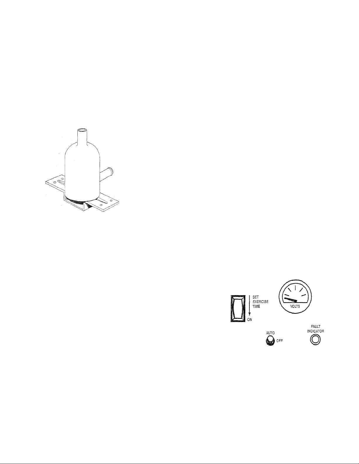
» Locate 'the rocker swatch on the control panel
identified wdtli the wnrds “Set Exercise Time”
(Figure 2.3).
» Push “Set Exercise Time” swdtch to the ON posi
tion for 20 to 30 seconds and dien release. The
swdtch will spring back into its original positLo.n
wdien released.
» Wait 30 seconds before setting the Auto/Off/
Manual swdtch to the AUTO position.
NOTE;
The unit -will exercise 20 minutes after it is set.
Example: Set - Noon; Exercise - 12:20 p.m.
-A CAUTION A-
If you switch the Auto/Off/Manual switch too
A
soon, the engine may start. If engine does
start, it will shut down automatically in about
two (2) minutes.
® Set the generator's main circuit breaker to its ON
(or closed) position.
• The generator is now programmed to start and
exercise eveiy seven days thereafter, on the day
and at the time of day the swdtch was activched.
0 Place a sign on tlie generator’s control panel and
on the transfer sv/itch that indicates the day and
time the generator tvill be exercising.
NOTE:
If the battery terminals are disconnected or the
control panel fuse is removed, the exercise
timer needs to be reset for automatic exercise
operation.
Figure 2.3 - "Set Exercise" Switch on Control Panel
MANUAL
2.8 OPTIONAL GTS TRANSFER SWITCH
This generator can be installed in conjunction wdth
a Generac GTS-type automatic transfer switch, if
desired.
The standard ATS-type transfer swdtch has no
sensing or controlling circuit boards. Instead, the
generator control console houses a control module
assembly (CfVLA), which controls all phases of oper
ation, including engine start-up and load transfer.
Page 13

Section 2 — Operation
Guardian Liquid-cooied 8 kW Generators
OPERATION
6
&
# 2.8.1 USING AN OPTIONAL GTS
_________
When you use a GTS-type transfer swatch, it con
trols automatic operation and automatic transfer
as follows:
• Solid-state circuits in the transfer switch monitor
utility power source voltage.
• When utilitjr source voltage drops below a preset
level, transfer swdtch action closes the engine cir
cuit. The engine then cranks and starts as con
trolled by the generator's control module circuit
board.
* After the engine starts and when the generator
A.C output voltage and frequency have reached a
preset value, transfer switch circuits signal the
transfer switch main contacts to move to the
standby power source side. Generator AC output
then pownrs load circuits.
TRANSFER SWITCH
_______________________
® When the utiliW power source voltage is restored
above a preset level and the return to utility
timer has timed out. the transfer switch solidstate circuits signal the switch main contacts to
move back to their utility power source side.
» The engine cooldown timer stains and times out.
Then, the transfer switch circuit board action
opens the engine run circuit. The engine then
shuts down.
NOTE:
If yonr generator is installed in conjunction
with an optional GTS-type transfer switch, refer
to the applicable transfer switch manual for
exact operating parameters and timing
sequences.
Page 14

MAINTENANCE
5izz=:0
Section 3 - Maintenance
Guardian Liquid-cooled 8 kW Generators
3.1 25-HOUR BREAK-IN PERIOD
The first 25 hours of operation constitute the breakn period for the standicy generator. Correctly breakng in the generator is essential to mitiiiriize oil connimption and macdmize engine performance. During
he break-in period, observe the ibllowing rules:
. Run the generator at va.rious elecuical loads for
the first 25 hours of operation, to help seat
engine piston rings properly.
For the next 75 operating hours, avoid light
electrical loads.
' During this period, load the unit at 50 percent or
more of its rated capacity (4,000 watts or more).
Repeated light electrical loads during the break-
in period can cause improper seating of engine
piston rings, resulting in blowb\^ and high oil
consumption.
. Check the engine crankcase oil level frequently
during the break-in period. It is normal for oil
consumption to be high during this period.
, xkfter the 25 hour break-in period is completed,
perform the tasks recommended under "25
Hour Checkup.”
.2 25-HOUR CHECKUP
tlloiving the first 25 hours of operation, contact an
tithorized sendee facility for tlie following mainte-
ince. The generator ovmer is responsible for all
targes.
Change the engine crankcase oil and filter.
Check all fluid levels (engine coolant, fuel, bat-
ter\" electrolyte fluid).
Inspect cooling system hoses for deterioration
and leaks, all hose clamps for tightness and
security.
Check fuel system lines for leaks, tightness and
condition.
Check fuel injection timing,
Check/Adjust engine governed speed (frequency).
Inspect engine belts for condition, proper tension.
Check for correct AC voltage output.
Check all generator receptacles and circuit
brealcers for condition and proper operation.
3 CHECKING THE ENGINE
OIL LEVEL
ter the 25-hour break-in period, check the engine oU
'el eveiy" eight hours or operation or at least once
ily before using the generator. For oil capacities, see
oecltications,” Section 1,7 (Page 6). For engine oil rec-
iinendations. see Section 1,9 (Page 7). To check the
gine oil level, proceed as follows (Figure 3.1):
Remove tlae dipstick and rvlpe it dry rvlth a
clean clotli.
S, Generac* Power Systems, !nc.
Install the dipstick cap; then, remove it again.
The oil level should be at the dipstick “Full”
mark. If necessary, add oil to the “Full” mark
only. DO NOT FILL ABOVE THE “FULL” MARK.
3.
Install the dipstick.
CAUTION M.
-A
Never operate the engine with the oil level
below the "Add" mark on the dipstick. Doing
this could damage the engine.
Figure 3.1 - Engine OH Servicing Points
Oil Filler
Cap
--------
3.4 CHANGING THE ENGINE
GIL AND FILTER
See Section 1.9, “Engine Oil Recommendsfoons” (Page
7), for die proper oil grade for your application.
NOTE;
The engine oil and filter should be changed after
the 25-hour break-in period. See the “Service
Schedule,” Section 3.13 (Page 16), for subse
quent oil and filter changes.
-A
.Any attempt to crank or start the engine before
A
it has been properly serviced with the recom
mended oil may result in an engine failure.
To change tiie oil and filter, proceed as follows:
Refer to tlie “Sendee Schedule,” Section 3.13 (Page
16), for engine oU and filter change frequencies.
Drain the oil while the eng,ine is still warm from run
ning. This means you should warm up the engine,
shut it down and drain It immediately as follows:
1. Remove tlie oil drain hose from its retaining clip,
located on the generator base frame.
2. Loosen and remove tlie oil drain hose cap, locat
ed on tlie base frame end of tlie hose. Drain tlie
oil completely into a suitable container.
CAUTiON
A-
Page 15

Section 3 — Maintenance
Guardian Liquid-cooled 8 kW Generators
MAINTENANCE
3. When aJl of the oil has drained, install and tight
en the oil drain hose cap.
4. Turn tile oil filter (Figure 3.1) countercloclcwise
and remove it. Dispose of the old filter.
5. Apply a light coating of engine oil to the seal of
new oil filter. Install tire filter and tighten by
hand only. DO NOT OVERTIGHTEN,
6. Remove the oil filler cap (Figure 3.1). Add the rec
ommended oil (see Section 1.9, Page 7). DO NOT
FILL ABOVE THE DIPSTICK ■‘FULL” MARK.
CAUTION A
-A
After refilling the crankcase with oii, always
check the oil level on the dipstick. Never
operate the engine with the oil level below the
"Add" mark on the dipstick. Doing this could
damage the engine.
--------
7. Start the engine and check for oil leaks.
8. Check the oil level after checking for leaks to
ensure that the oil is filled to the proper level.
3.5 CHANGING THE ENGINE
AIR CLEANER
To replace the engine air cleaner, (Generac part
number 70941), simply remove the air cleaner
cover and replace the air filter making sure it is
positioned properly before reattaching the cover.
Figure 3.2 - Engine Air Cleaner
AIR CLEANER
3.6 BATTERY MAINTENANCE
The battery should be inspected per the “Service
Schedule,” Section 3.13 (Page 16). The following
procedure should be followed for inspection:
1. Inspect the battery posts and cables for tight
ness and corrosion. Tighten and clean as
necessary.
2. Check the battery fluid level of unsealed batter
ies and, if necessar/, fill wth DISTILLED
WATER ONLY. DO NOT USE TAP WATER IN
BATTERIES.
3. Have the s tate of charge and condition checked.
This should be done mth an automotive-type
battery hydrometer or load test.
-АЕВШЗ A-
Storage batteries give off explosive hydrogen
gas. This gas can form an explosive mixture
around the battery for several hours after
charging. The slightest spark can ignite the gas
and cause an explosion. Such an explosion can
shatter the battery and cause blindness or
other injury. Any area that houses a storage
battery must be properly ventilated. Do not
allow smoking, open flame, sparks or any spark
producing tools or equipment near the battery.
Battery electrolyte fluid is an extremely caustic
A
sulfuric add solution that can cause severe
burns. Do not permit fluid to contact eyes, skin,
clothing, painted surfaces, etc. Wear protective
goggles, protective clothing and gloves when
handling a battery, if you spill the fluid, flush
the affected area immediately with clear water.
Do not use any jumper cables or booster bat
A
tery to crank and start the generator engine, if
the battery has completely discharged, remove
it from the generator for recharging.
(TPANSPAREMT ENCLOSURE FOR CLARITY)
See tile “Service Schedule," Section 3.13 (Page 16),
for recommended air cleaner maintenance.
-----
Ak WARNING
Be sure the utility power supply is turned off,
A
or sparking may occur at the battery posts as
you attach the cables and cause an explosion.
Be sure the Auto/Off/Manual switch is set to
the OFF position before connecting the battery
cables. If the switch is set to AUTO or MANUAL,
the generator can crank and start as soon as
the battery cables are connected.
Generac® Power Systems, inc. 13
---------
Page 16

MAINTENANCE
AIH OUTLET
Section 3 - Maintenance
Guardian Liquid-cooled 8 kW Generators
Figure 3.3 - Cooling Vent Locations
GJJTHnH
AIR INTAKE
CT
3.7 COOLING SYSTEM
Air Intalce and outlet openings in the generator com
partment must be open and unobstructed for contin
ued proper operation. This includes such obstruc
tions as high grass, weeds, brush, leaves and snow.
Witiiout sufficient cooling and ventilating air flow, the
engine/generator quiclfly overheats, which causes it
to shut down. (See Figure 3.3 for vent locations.)
-A WARNING A-
The exhaust system of this product gets extreme
ly hot and remains hot after shutdown. High
grass, weeds, brush, leaves, etc. must remain
clear of the exhaust. Such materials may ignite
and burn from the heat of the exhaust system.
3.8
OVERLOAD PROTECTION FOR
ENGINE DC ELECTRICAL SYSTEM
Engine cranlting, start-up and running are con
trolled by a solid-state engine controller circuit
board. Battery voltage is delivered to that circuit
board via a 30-arnp fuse. These overcuiTent protec
tion devices will open if the circuit is overloaded,
-A CAUTION A"
A !f a circuit breaker opens or a fuse element melts,
you should find the cause of the overioad before
resetting the circuit breaker or replacing the fuse.
3.9 FUSE
The generator panel's 30-amp fuse (Figure 2.1, Page
8) protects the DC control circuit against overload.
The fuse is wired in series with the battery output
lead to the panel. If the fuse element has melted
open, you cannot crank or start the engine. You
siiould replace the fuse using only an identical 30amp replacement.
3.10 ENGINE COOLANT
Check the coolant level in the coolant recovery bot
tle at least once daily or prior to use. Add the rec
ommended coolant rruxture (see Section 1.7.2, Page
6) as necessary; the bottle should he kept half full. If
desired, you may add a high quality rust inliibitor to
the recommended ,50-,50 coolant rruxture. If added
consistently, the recommended rnixture will protect
the unit against freezing temperatures.
Periodically remove the radiator pressure cap to
make sure the coolant recover}' system is function
ing properly. Coolant should be at the bottom of tire
radiator filler neck. If the coolant level is low,
inspect the gasket in the radiator pressure cap.
Replace the cap, if necessary'. To have the pressure
cap tested, contact a Generac/Guardian
Authorized Dealer, inspect the cooling system and
coolant recovery system for leaks.
-A A-
Do not remove the radiator pressure cap while
the engine is hot or serious burns from boiling
liquid or steam could result.
Ethylene glycol base antifreeze is poisonous.
A
Do not use your mouth to siphon coolant from
the radiator, recovery bottle or any container,
Wash your hands thoroughly after handling.
Never store used antifreeze in an open contain
er because animals are attracted to the smell
and taste of antifreeze even though it is poi
sonous to them.
-A CAUTION A-
Do not use any chromate base rust inhibitor with
ethylene glycol base antifreeze, or chromium
hydroxide ("green slime") will form and cause
overheating. Engines that have been operated
with a chromate base rust inhibitor must be
chemically cleaned before adding ethylene glycol
base antifreeze. Using any high silicate antifreeze
boosters or additives also will cause overheating.
We also recommend that you DO NOT use any
soluble oil inhibitor for this equipment.
Page 17

Section 3 — Maintenance
Guardian liquid-cooled 8 kW Generators
MAINTENANCE
3.11 MISCELLANEOUS MAINTENANCE
# 5.11.1 CLEANING THE GENERATOR
Keep your generator as clean and as diy^ as possi
ble. Dirt and moisture that accumulate on internal
generator windings have an adverse effect on insu
lation resistance.
Periodically, clean the generator’s exterior surfaces.
soft brush may be used to loosen caked on dirt.
You can use a vacuum system or clr/, low pressure
air to remove any accumulations of dirt. The gener
ator is housed inside an all-weather enclosure:
clean the enclosure with a soft, damp cloth or
sponge and water.
Once each year, have tlie generator cleaned and
inspected t3V a Generac/Guardian Authorized
Dealer. Sertdce technicians wall use diy, low pres
sure air to clean internal windings. Parts Inside the
control console should be cleaned and inspected at
this time as w^ell.
F'ina.lly, have the insulation resistance of stator and
rotor wdndings checked. If insulation resistances are
excessively low. the generator may require diydng.
^ 3.11.2 RODENT PROTECTION
____________________
The intrusion of rodents into the generator set can
cause a wide range of problems, from failure of the
unit to start, to personal injury and, in extreme circumsta.nces, short circuit or fire. .Although the unit
wms designed to limit this problem, you can take
further precautions to help minimize both the
chance of rodent entry and the extent of any dam
age, You should inspect the unit at regular inter
vals for signs of rodent intrusion. In addition,
ensure that all access doors are tightly closed and
secured at all times. If you detect intrusion and/or
damage, contact your nearest Generac Authorized
Service Dealer immediately.
_____________
3.12 GUT OF SERVICE PROCEDURE
♦ 5.12.1 REMOVAL FROM SERVICE
If you cannot exercise the generator even/ seven
days, and it is to be out of sertdce longer than 90
days, prepare the generator for storage as follows:
1. Start the engine and let it warm up.
2. Close the fuel shutoff valve in the fuel supply
line and allow the unit to shut dowm.
_______________
3. Once the unit has shut downs, it will signal a
fault on the control panel.
4. Set tlie Auto/Off/Manual switch to OFF and
turn off the utility powder to tlie transfer switch.
5. While ttie engine is still warm from n.m,ning, drain
the oil completely. Reiill the cranitcase witli the
recommended oil (see Section 1.9, Page 7).
6. Attach a tag to tlie engine indicating the viscos
ity and classification of the oil in the crankcase.
7. Remove the battery and store it in a cool, dry
room on a wooden boa.rd. Never store the batter>' on any concrete or earthen floor.
8. Clean and wipe the entire generator.
# 5.12.2 RETURN TO SERVICE______________________
To return the unit to sendee after storage, proceed
as follows:
1. Verify that utility' power is turned off to the
transfer switch and that the Auto/Off/Manual
switch is set to OFF.
2. Check the tag on the engine for oil viscosify and
classi,fication. Verify that the correct recom
mended oil is used in engine (see Section 1.9.
Page 7). If necessa.r>i clradn and refill with the
proper oil.
3. Check the barterv. Fill all ceils to the proper
level witli distilled water. DO NOT USE TAP
WATER IN THE BATTERY. Remove the batteiy
before charging. Recharge the batteiy' to 100
percent state of charge, or. if defective, replace
the batteiy' with a 12-volt DC Group 26F battery
rated for 75 amp hours (part # 77483).
4. Clean and wipe the entire generator.
5. Reconnect the battery. Obsen'e battery pokirity.
Damage will occur if tlie battery is connected
incorrectly.
6. Open the fuel shutoff valve.
7. Start the unit by moving the Auto/Off/Manual
switch to MANUAL. Allow the unit to warm up
thoroughly.
8. Stop the unit and set tlie Auto/Off/Manual
switch to OFF.
9. Turn on the utility power to the transfer switch.
10. Set the Auto/Off/Manual switc.h to AUTO.
11. Your generator is now ready for sendee.
Generac® Power Systems, Inc. 1 5
Page 18

Section 3 - Maintenance
MAINTEMANCE
Guardian Liquîd-cooied 3 kW Generators
|3J3 SERVICE SCHEDULE
ATTENTiON: !t is recommended that a!! service work
be performed by your nearest Generac/Guardian Authorized Dealer.
SYSTEM/COMPONENT
X = Action
R = Replace/Adjust as Needed
* = Notify Dealer
if R.epair is Needed.
■FUEL
Fuel level
;
Fuel lines, connections
and filters*
LUBRICATION
Oil level
; Oil
1 Oil filter
: Oil line leakage* 1 X
! COOLING
Engine cooling -system*
; Coolant level
Coolant* X
1 Enclosure louvers X
: EXHAUST
Eichaust svstem
Retorque Exhaust Manifold* X
BATTERY
Electrolyte fluid level
Charge and condition
FAN BELT
Tension and condition*
ENGINE
Retorque cylinder head*
Retorque intake manifold*
Starter motor* X
DC alternator* X
Air cleaner X R 1
Compression*
Valve clearance*
Governor* X
SafeA detdces*
Iniection svstem*
GENERAL
Overall condition
Exercise svstem
COMPLETE TUNE-UP*
inspect
X
A'
X i
X
X
X
X i 1 j AFTER 25-H BRE.AK-IN, W
X ! R 1 X i W, EVERT 250 H / 6 M
X
X
X
X
X
X
X ! R
X
TO BE COMPLETED BY A GENERAC/
GUARDIAN AUTHORIZED DEALER
PROCEDURE
Change
X'
X
R
R
R
R i
R
R
R
Clean
X
X
FREQUENCY
D = DaiN W = Weekly
M = Monthly Y = Y'early
H = Hours
AFTER 25-H BRE.AK-IN,
D / BEFORE USE
AVTER 25-H BRE.MÎ-IN,
EVERY 250 H / 6 M
EVERY 8 H /D
AFTER 25-H BRE.AK-IN.
EVERY 250 H / 6 M
AFTER 25-H BREAK-IN,
EVERY 250 H / 6 M
: EVERY 100 H
AFTER 25-H BREAK-IN,
EVERY iOO H / M
AFTER 25-H BRE-.AK-IN,
D / BEFORE USE
EVERY 500 H / Y
EVERY 250 H / 6 M
EVERY 100 H / M
FIRST 100 H ANE
EVERY 800 H
1 AFTER 25-H BREAK-IN,
! EYERY 250 H / 6 M
FIRST 100 H AND
EVERY 800 H
FIRST 100 H AND
EVERY 800 H
EVERY 500 H
EVERY 500 H ARiD Y
EVERY 500 H
EVERY 800 H
EVERY 800 H
AFTER 25-H BRE-AK-IN,
EVERY 250 H/6 M
EVERY 6 M
EVERY 3 M
AFTER 25-H BREAGIN, W
W
Y
Page 19

4.1 TROUBLESHOOTING GUIDE
Section 4 — Troubleshooting
Guardian Liquid-cooled 8 kW Generators
TROUBLESHOOTING
PROBLEM
CAUSE CORRECTION
The engine will not crank. 1. Fuse blown
2. Loose, corroded or defective
battery cables
3. Defective starter contactor
4. Defective starter motor
5. Dead Battery
The engine cranks but
will not start.
1. Out of fuel
2. ' Defective fuel solenoid (FS)
3. Open #14 wire from
engine control board
4. Dirty/Blocked air filter
5. Amto/Off/Manual Switch
in OFF position
The engine starts hard
and runs rough.
1. Air cleaner
plugged or damaged
2. Dlrty/Blocked air filter
The engine starts, but then
shuts doLTO.
1. Engine oil level low
2. Defective low oil
pressure switch
3. Defective high temperature
switch
4. Defective control board
5. Low coolcmt level
6. Defective low coolant switch
7. Engine temperature high
8. Loss of AC sensing to
control boa.rd
1. Replace fuse.
2. Tighten, clean or replace
as necessary.
3. *
4. *
5. Charge or replace battery.
1. Replenish fuel.
2. *
3. *
4. Clean or replace as required.
5. Reset to AUTO or IvLwMUAL.
1. Check, clea.n or replace air cleaner.
2. Clean or replace as required.
1. Check oil and add oil as needed.
2 *
O .1.
o.
4. *
5. Check coolant level, repair leaks
and refill.
6. *
7. Check engine cooling airflow.
R ^
The Auto/Off/Manual switch
is set to OFF, but the engine
continues to run.
There is no AC output from
tlie generator.
There is no transfer to
standby after utility
source failure.
*Contact your nearest Generac/Guardian Authorized Dealer for assistance.
1. Defective switch
2. Defective control board
1. Generator main line circuit
breaker open
2, Generator internal failure
1. Generator main line circuit
breaker open
2. Defective transfer svfitch coil
3. Defective transfer relay
4. Transfer relay circuit open
5. Defective control logic board
1. *
0
1, Reset circuit breaker
to ON (or closed].
2. *
1. Reset circuit breaker
to ON (or closed).
2. *
3. *
4.
5. *
Generac* Power Systems, Inc. '1 *7
Page 20

oWiTi'l fCTOW
_r ELECTRICAL
DATA
Section 5 — Electrical Data
Guardian Liquid-cooled 8 kW Generators
Wiring Diagram (Control Pane!) - Drawing No. C2516-A
Page 21

Section 5 - Electrica! Data
Guardian Liquid-coded 8 kW Generators
Electrical Schematic (Control Panel) - Drawing No. C2669-A
WiTm nrmT]
ELECTRICAL
DATA
Page 22

Tini {HPi piFoinn
ELECTRICAL
DATA
-L
Section 5 — Electrical Data
Guardian Liquid-cooled 8 kW Generators
Wiring Diagram (1.0 Liter Engine) - Drawing No. C4954-
On \A/ r
hWT- HIGH G/ATEH TEMP.
lOS- low oil press SW.
SC - STARTER CONTACTOR
SM - STARTER MOTOR
SWT- SENDER VVATER TEMP
WLS- WATER LEVEL SENSOR
5\/^t:i=rr»5=;. Inc.
Page 23

Section 5 — Electrical Data
Guardian Liquid-cooled 8 kW Generators
Electrical Schematic (1,0 Liter Engine) - Drawing No. C4955-
CUSTOMER
120V/i5A UTILITY
CONNECTIDN
niFoTri rifiJoTir
ELECTRICAL
DATA
EZL
■rr \
'iZy
BLACK-
DCA
DCR
EH
FP
GP
HW
lDS
SC
SM
S W T
WLS
- DC ALTERMATDR
- DC vdltagl regulator
“ lNCINE Hl_A i EK
- ^UEL SHIJTOF“ SQlENGID
- FUEL PUMP
- Glow plug
- HIGH WATER TEMP,
- SWITCH, caw GIL PRESSURE
- STARTER CGMTACTuR
- starter METER
- SLMDER water temp
- WATER _EVEL SENSaP
Generac” Power Systems. Inc. ST
Page 24

^PARTS
LISTS
Section 5 — Exploded Views and Parts Lists
Guardian Liquid-cooled 8 kW Generators
Compartment - Drawing No. C2436-B
2S CBenerac® Power Systems, Inc.
Page 25

Section 6 — Exploded Views and Paris Lists
Guardian Liquid-cooled 8 kW Generators
Compartment - Drawing No. C2436-B
’’EM
PART NO.
*02433 1 CORNER POST, LH. REAR
1
*02434
2
A3443
3
4 A3444 1
5 A3445
6 A3446
A3447 1
7
A7198 1
8
A3449 2 DOOR, SIDE
9
11
A3451
12 A7197 1
13 A3453
14 A3454
*02435
16
*C2435A 1 DUCT, LH. REAR CORNER
C2755A
17
C2755B 1 DOOR, REAR (INSUL.)
18
C2755C
19
C2755D
20
C2755E
21
C2755F
22
C2755N VENTURI, TOP (INSUL.)
23
QTY.
DESCRIPTION
ITEM
24
CORNER POST, RH. REAR 25
1
1 PANEL. REAR BOTTOM
PANEL, REAR TOP
PANEL. SIDE
3
PANEL, RH. SIDE BOTTOM
1
26
27
28
CORNER POST, LH. FRONT 29
CORNER POST, RH. FRONT
30
1 PANEL, FRONT TOP
PANEL, FRONT
1 DOOR, REAR
31
32
33
1 TOR ROOF 34
DUCT, RH. REAR CORNER 35
1
POST
36
POST
37
1 PANEL, REAR BOTTOM 38
(INSUL.) 39
40
1
DOOR, FRONT (INSUL.)
2 CORNER POST, FRONT
(INSUL.)
1 DOOR, LEFT SIDE (INSUL.)
4 PANEL, SIDE (INSUL.)
41
42
FOR REF. ONLY (SEE 02438 CONTROL PANEL FOR
DE \lLSi
PART NO. QTY.
DESCRIPTION
C2755P 1 ROOF, TOP (INSUL.)
C2755M
C2755G 1
C2755H 1
1 DOOR, RIGHT SIDE (INSUL)
AIR DUCT, BOTTOM (INSUL.)
AIR DUCT. FRONT RH,
(INSUL.)
C2755J
C2755K
1
AIR DUCT, LH. SIDE (INSUL.)
AIR DUCT, FRONT LH.
1
(INSUL.)
C2755L 1
22473
AIR DUCT, RH. SIDE (INSUL.)
50 FLAT WASHER-M6-1/4"
22097 32 LOCK WASHER-M6-1/4"
22127 6
49813
42568 18
NUT. HEX-1 M"-20
NUT, HEX-M6-1.0
18
CAPSCR..HEX HD.-M6-1,0 x 20
LONG
67577
22413
67042
78115
A3133A 2
A3133B
A3133C
A3133D
A3359 40
A3360 40
SPEED NUO1/4"-20
16
16 CAPSCR., HEX HD,-1/4"-20 x 1
4
LATCH & CAM
4
WASHER. SELF LOCK/DOME
HINGE, SLIP-MALE L.H.
HINGE, SLIP-FEMALE L.H.
2
d
HINGE, SLIP-MALE R.H.
d
HINGE, SLIP-FEMALE R.H,
BHSCS-M6 X 16 S.S.
SHAKEPROOF, INT.-M6 S.S.
ör-iVA/pan S V «=; ft {= m «=:. inrt.
Page 26

.PARTS
LISTS
Section 6 — Exoioded Views and Parts Lists
Guardian Liquid-cooled 8 kW Generators
Controi Pane! - Drawing No. C2438-3
©
iS^^ooo.;
1©;
»67680 VOLT. RlG, shown IN THIS VIEW
IS USED ON 30 UNIT DMLY
2^4 Generac® Power Systems, Inc.
Page 27

Section 6 - Exploded Views and Parts Lists
Guardian Liquid-cooled 8 kW Generators
Control Pane! - Drawing No. C2438-8
:'E!V! PART NO,
1
C2430 1 CONTROL PANEL BACK/
QTY. DESCRIPTION ITEM PART NO.
BOTTOM
2 C2719
SILKSCREEN-CONTROL 37
1 '
PANEL 38
3 C2431
C2431A
4
83048
CONTROL PANEL L.H, SIDE 39
1
1 CONTROL PANEL R.H, SIDE
VOLTAGE REGULATOR
1
41
1-PHASE 60HZ
67680
VOLTAGE REGULATOR
1
3-PHASE BOHZ 43
C2434
5
CORNER POST, RH REAR 45
1
(PANEL SUPPORT) 46
6 C2433
CORNER POST, LH REAR 47
1
(PANEL SUPPORT
7 77906 1 CIRCUIT BREAKER-MAIN 48
(35A-2P-BQ2) 49
57906
CIRCUIT BREAKER-MAIN
(35A-3P-BQ3)
S C2435 1 DUCT. R.H. R.R, CORNER 53
75589 1 BRACKET, VOLTAGE
9
REGULATOR
76039
10
11 51716 2
12 90426
90427
13
14 40295
40292
15
C2435A
16
о
SCREW, PPHM M5-.8 x 40MM
HEX NUT M5-0.8
PPHMS #10-32 X 3/8“ S.S.
О
FLAT WASHER #10
3
n
LOCK WASHER #10 58 C2428
0
HEX NUT #10-32
5
DUCT, LH REAR ICORNER
1
POST)
17 C2515 1 HARNESS, CONTROL 61
PANEL “P“
18 29333 4 TIE WRAP T LG.
19 76061 1
81988 1
20
21 82573
DECAL. TERMINAL STRIP 64
DECAL SET EXERCISE TIME 65
1
SWITCH ROCKE.R(SET
EXERCISE TIME) 67 C2265 9
22 76020
64009 LIGHT FAULT INDICATOR
23
24 61945
A2560
25
C5454
26
27 22473
55349
28
58568
29
58568
1
SWITCH-AUTO/MANUAL/OFF
1
SWITCH, VOLTAGE SELECTOR
1 RELAY IP 50A/12V
1 CABLE, NYLON CONTROL
PANEL
2
WASHER. FLAT 1/4"
1 INSULATOR
2 CURRENT TRANSFORMER
50/5 n PHASE)
CURRENT TRANSFORMER
3
73 36935
75
76
77
78
79
50/5 (3 PHASE)
70081
30
70043
31
32 32300
49939 RECTIFIER
33
34
22668
1 HOUR METER
1 VOLTMETER DC (BATTERY)
HOLDER, FUSE
1
FUSE. 30A.
1
30
81
82 22473
83
70042 1
35
36 700-^5 1
71668
70370 1
30468
71938A 1
40
23762 1
22097 22
42
C1914A
48766
56967 2
79246
48468 1
14
51
22155
22142
52 22145
33121
22152
54
23897
55
22158
56
57 A2419
24 SWG FASTENER 1/4"-20 x
12
34616
59
57335
60
46669 7
57907 1
62
C2484 2
63
22264 7
39782
75545 1
66
61979
68
69 57073
33530 2
70
22129
72
22259
54199
C2512
75595
A7215
C2473
22287
22127
DESCRIPTION
QTY.
HERTZ METER 60HZ
AC AMMETER 0-200
AC VOLTMETER 0-500
1
WASHER, MICA
STEP, WASHER NYLON
1
VOLTAGE REGULATOR, D.C.
WASHER, EXTERNAL SHAKEPROOF
WASHER. LOCK 1/4"
HINGE CONTROL PANEL
1
BLOCK TERMINAL (2)
1
PLUG, PLASTIC .37
4
HHCS M6-1.0 X 16 LG. W/LOCK
WASHER
CIRCUIT BREAKER 8A
#6 LOCK WASHER
HHCS 5/16”-18 X 3/4"
4
A.
WASHER FLAT 5/16"-M8
#10-32 X 1./2" LG. HEX HD
2
MACH. SCREW
#10 LOCK V/ASHER
5
#10 FLAT WASHER
6
#10-32 HEX NUT
5
1/2" LG.
SWG FASTENER #6-32 x
1/2" LG.
STRAIGHT CONNECTOR
1
TERMINAL BLOCK
1
JUMPER, TERMINAL BLOCK
RESISTOR, 10 OHM
BRACKET, PANEL SUPPORT
WASHER. LOCK M4
BRACKET, CIRCUIT BREAKER
1
COVER, CIRCUIT BREAKER
SWG FASTENER M4-0.7 x
12 LG.
BAR, BUS NEUTRAL STAR
1
STUD, JUNCTION BOX
1
PHMS #10-32 X 5,/8"
WASHER, LOCK 5/16"-M8
4
PPHMS #10-32 X 3/4"
2
d
HEX NUT 5/16"-18
DECAL, HIGH VOLTAGE
1
WIRE CONNECTOR 1"
2
i
CMA, BOX
SW FASTENER 1,''4"-20 x 5/8"
4
W.A/VASHER
BRACE, TOP REAR
1
2 HHCS, 1/4"-20 X 3/4"
n
FLAT WASHER, 04"
C
HEX NUT 1/4--20
2
Generac® Power Systems, Inc. S5
Page 28

.PARTS
LISTS
Section 6 — Exploded Views and Parts Lists
Guardian Liquid-cooled 8 kW Generators
Engine Common Parts - Drawing No. C5009-B
es
o o
x:
o a
lD [X
SB Generac'’ Power Systems, Inc.
Page 29

Section 6 - Exploded Views and Parts Lists
Guardian Liquid-cooled S kW Generators
Engine Common Parts - Drawing No. C5009-B
.PARTS
LISTS
ITEM
PART NO.
1
72501 2 MOUNT, ENGINE
70936
c
rs
75672
o
4
51769 4 WASHER. LOCK Ml 2 46
46233
5
57642 1
6
/ 46526 1
42909
8
22129
9
77909 1
10
QTY. DESCRIPTION ITEM
2 DAMPENER, VIBRATION
4
HHCS Ml2-1.25 X 40MM
1
V-BELT30-1/8" LONG
HHCS M10-1.5 X 40MM
WASHER. LOCK M10 49
3
HHCS M8-1,25 X 30MM
WASHER, LOCK M8
16
BRACKET, ALTERNATOR
11 22145 1 WASHER, FLAT M8 53
45771
12
22097
13
14 57058 2
77910
15
16X 47411
17 50311
A1354
18
39294
19
20 59399A 1
3
NUT, HEX M8-1.25
14 WASHER. LOCK M6
HHCS M6-1.0 X 55MM
1
FAN, ENGINE
C
sj
HHCS M6-1.0 X 16MM 58
1
SPACER 59
1
DC ALTERNATOR
2
CLAMP, HOSE #44
INTAKE HOSE
21 35685 1 CLAMP. HOSE #28 63
22
23
70941 1
C4206
FILTER, AIR
1
ENGINE HARNESS
PART NO.
44 52221
45 30096
74819
40173
47
52221
48
52221 1 HOSE 5/16" X 205MM LONG
52221
50
22097
51
52219
52 '
50S67 1 HOSE 5/8" I.D. X 18"
50967
54
57823 6
55
72573
56
69860E
57
22507
53667 2
42574 1 ADAPTOR
61
84033
62
99236
68-44114
64’
42907 5
65
24 C4695 1 BRACKET. FUEL PUMP 67 69811
65852
25
71952 1 WASHER, LOCK 69
26
27 71912
75673
28
75674 1
29
A4119 1 FUEL PUMP ASSEMBLY 74
30
84918
31
42907 3
32
75692 1 SHIELD, HEAT
33
45757
34
22261
35
74808
36
37 52233
39450 2 90 DEG. ELBOW BARB
38
74823
39
68736-3
40
6S736-A
41
28739
42
70928
43
1 CLAMP, SPRING
1
PPHMS M5-0.8 X 8MM 70
-j
MANIFOLD EXHAUST
GASKET EXHAUST ADAPTOR
1
BLOCK HEATER
HHCS M8-1.25 X 16MM 76
6 HHCS M6-1.0 X 16MM 77
1
STAR WASHER M8
i
CONNECTOR. ADAPTOR 80
2
CONNECTOR, ADAPTOR TEE
/1
CLAMP, HOSE 82 87458
1
HOSE 3/16" I.D.
1
HOSE 3/16" I.D. MOUNT
1
TIE WRAP
3 CLAMP, HOSE
78
81
83
84 357-70939 1
85
63
72
73
75
84432
57522
57824
46852
79929
77444 1
77913
35468
51730
71956
A7803
66246
87469
661-70939
QTY.
DESCRIPTION
1
HOSE 5/16“ I.D. X 170MM
LONG
Í
FITTING, BARBED STRAIGHT
1
CONNECTOR FITTING
CLAMP, HOSE
6
1 HOSE 5/16" X 570MM LONG
1 HOSE 5/16" X 120MM LONG
2
WASHER, LOCK 1/4"
1 FITTING, BARBED STRAIGHT
HOSE 5/8" I.D. X 14"
1
CLAMP, HOSE #10
1
FITTING, OIL
1
HOSE. DRAIN
HHCS 1/4“-20 X 1./2”
2
SENDER, WATER TEMP.
1 FITTING, BARBED STRAIGHT
3/4“ NPT X 5/8"
SWITCH, OIL PRESSURE
1
i
ASSEMBLY. GROUND STRAP
HHCS M8-1.25 X 16MM
1 CAP, HEX 1/xT DÍA.
1
ADAPTOR, SENSOR
1 WATER LEVEL SENSOR
CLAMP, HOSE 316
6
1 TAPTITE #10-32 X 1/4"
TEE 1 X 1 X
1
UPPER RADIATOR HOSE
LOWER RADIATOR HOSE
1
1 3/8" X 1/4" REDUCER
BUSHING
HHCS M8-1.25 X 60
4
4
WASHER, FLAT M8
1" PRE-ALARM TEE
1
WTS PREHEAT & SHUT DOWN
1
230 DEG.
5/8" O.D.TUBE
1
THERMOSTAT 5/8" TUBE
1
GASKET EXHAUST ISM
FUEL FILTER ASSEMBLY ISM
1
rORGUE FT. LBS,
X.
* NOT SHOWN
Generac* Power Systems, inc.
S7
Page 30

^PARTS
LISTS
Section 6 - Exploded Views and Parts Lists
Guardian Liquid-cooled 3 kW Generators
Generator - Drawing No. A4671-B
3<4 j 0
SS Generaci Power Systems, ine.
Page 31

Section 6 — Exploded Views and Parts Lists
Guardian Liquid-cooled 8 kW Generators
Generator - Drawing No. A4671-B
iEM PART NO. QTY,
1 77900 1
2 42558 1
3 48189 2
87714A
4
1
5 74243 1
72512 4
S
7 22097
8 WASHER. LOCK-M6 27*
8 22473 8
9 77043C 1
10 76019A 1
11
69804A 1
14 69892
■ 5
70992 1
16
98323
17 75554
18
22129
i
1 PLATE. COVER
¿1
24
19 47411 4
20
134-70939
21 20747
1
2
DESCRIPTION
ROTOR ASSEMBLY-8KW 22
KEY
ITEM PART NO.
46526
23 22131
PIN, DOWEL 24 73450B 1
HOUSING, BLOWER 25 ■
49814
QTY.
DESCRIPTION
33
WASHER, LOCK
7 WASHER
PLATE, ENGINE
•o
O
CAPSCREW, HEX HEAD-MI 0-
SCREEN, AIR OUTLET 1.5 X25MM LONG
CAPSCREW. HEX HEAD-M6-
26^^' 51756
10
CAPSCREW, HEX HEAD-M10-
1.00 X 8MM LONG 1.5 X 20M.M LONG
12
42907
CAPSCREW, HEX HEAD-M8-
WASHER, FLAT-M6 1.25 X 16MM LONG
FLEX CONDUIT-3/4" l.D.x 10"
28 73451
1
ASSEMBLY, FLYWHEEL &
LONG RING GEAR
STATOR ASSEMBLY-8KW
29**
62963
6
CAPSCREW, HEX HEAD-MI 0CARRIER. REAR BEARING 1,25 X 30MM LONG
GASKET. REAR BEARING 30
CARRIER
31 53557
72578
1 SPACER. ATR SHAFT
1
BOLT, HEX HEAD-MI2-1,75 x
ARRESTER, FLAME 40MM LONG
BOLT, STATOR
33 73A54A
WASHER, LOCK-M8 34*
32
51769
75789
1
WASHER, LOCK-MI2
1
PLATE. COUPLING
12 SOCKET HEAD CAPSCREW.
CAPSCREW, HEX HEAD-M6- 5/16-18 x3,/4"
1.00 X 16MM
MOTOR, STARTER 36
SCREW, SOCKET-HEAD M10- 37
35 73452
73455
63212
1.5 X 35MM LONG (391 821308
1 HUB, DRIVE
-i
1 FAN
1
GROMMET RUBBER
1
SENSOR, RPM
=MON-GUARDiAN UNIT
TORQUE FT LBS,
12
42
/far* 5^\
Page 32

^PARTS
LISTS
Section 6 — Exploded Views and Parts Lists
Guardian Liquid-cooled 8 kW Generators
CMA Assembly - Drawing No. S1086-C
CO
o
ay
/ /V
/
/ /
/' /■'
..x /,
'-'t“-/-A,
■'vT'-' \
/X\ X
/A
/ /
/ /
/
in /
/
<7>
\
A.
—. ’"x
\ \ ' /
\ 'x\ /'
\V /'
1/'
\
-mMM\
S
‘
X
./ \ '
—
------
, ^X/
...V—^
.. /
/
/ / ^ /'■
o
Cvl
03
CO
Cd
/ CO /
/
CO
CM
CM
J i
/ /
/
CD
30 CSenerac® Power Systems, Inc.
CD
,'/ / /
/
V / /
03'
LO,
Page 33

Section 6 — Exploded Views and Parts Lists
Guardian Liquid-cooled 8 kW Generators
CMA Assembiy - Drawing No. 81086-C
ТЕМ PART NO.
1
76009A 1
2
72566
о
О 80882
4
74978 1
5
47822
6
75476
7
83264
8 22985 4
9 22264
10 51787
11
79847
QTY.
DESCRIPTION
BOARD. CIRCUIT-DC 12
CONTROL/CRAMK LATCH
4
STANDOFF, CIRCUIT BOARD
SUPPORT
4
SCREW, PPH TAPPING #6 x 13*
5/8"
DECAL, TERMINAL STRIP
1
BLOCK. TERMINAL STRIP 16
2
SCREW, PPHM M4-0.7 x 16MM 17*
1
TRANSFORMER 24VA. 12 SEC
WASHER, FLAT M4
4
WASHER, LOCK M4
2 HHCS M4-0.7 X 16
1
BOX. CMA
ITEM
PART NO. QTY.
A8504
A850-1A
22661V .083’ HEAT SHRINK RED ,19
14
15
38057 2
584A3 2
8122-i 1 DECAL, MFG NAMEPLATE
79682 1 WIRE HARNESS
18
19
86093 2 DECAL, CMA WARNING
83736 1
20 51715
21
74495
77^01
‘NOT SHOWN
DESCRIPTION
1
DECAL. COVER-CMA (MODEL
921. 863,865)
1
DECAL. COVER-CMA (MODEL
94281
GROMMET
CRIMPTITE
DECAL, CSA
NUT, HEX M4-0.7
2
1 COVER, CMA BOX (921,863,
865, 9428)
1
COVER, SILKSCREENED
Page 34

.PARTS
LISTS
Section 5 - Exploded Views and Parts Lists
Guardian Liquid-cooled 8 kW Generators
Mounting Bass - Drawing No. C2655-B
/
(
>li
!
c
CD
:,_i
LJ
n
\
C
\
32 Generac® Powpr Systems, inc.
Page 35

Section 6 — Exploded Views and Parts Lists
Guardian Liquid-cooled 8 kW Generators
Mounting Base - Drawing No. C266S-B
TEM
PART NO.
1
A1492
2 A7200
A7307
3
4
A7726
A7727
5
7
AA285
QTY. DESCRIPTION
1 FUEL CAP KELCH200751
BASE FRAME ASSEMBLY
1
BRACKET, FRONT FRAME
1
ALT MNT ASSEMBLY, R-SiDE
1
ALT, MNT. ASSEMBLY. L-SIDE
1
2
BRACKET, ENGINE MOUNT
8 21538G 2 FUEL DIP PIPE, 250MM
21973A
10
11
12
9
26847
26924
A57^6
1
GAUGE, FUEL LEVEL 281
2 BREATHER
1
90 DEG. ST ELBOW 3/8 NPT
2
BRACKET, RADIATOR
SUPPORT
35472
13
14 59502
1 6 70936
17
52221 1 5/16 I.D. HOSE X 800MM 36 63831 2 PIPE PLUG 1-1/4^' SO, HD.
2
HOSE CLAMP, SIZE #6
1
BARBED 90 DEG.1/4 x 9/16
4 VIBRATION ISOLATOR
20
PART NO.
67982
ITEM
21 35468
23 42568
24
49813 9 M6-1.0 HEX FIN. NUT
25 22473
22097
26
27
39253 38 M8-1.25 X 20 HHCS
45771
28
29 22145 50
22129
30
31
¿9814
32 46526 4
33
A4160
34 68-44114 1
35
22261
QTY.
DESCRIPTION
1
BARBED STRAIGHT, 5/16 x 3/8
1
REDUCER BUSHING 3/8 x 1/4
9
M6-1.0 X 20 HHCS
24
1/4 SAE FLAT WASHER
25 1/4 SPLIT LOCKV'/ASHER
16
M8-1.25 HEX FIN. FULL NUT
5/16 SAE FLAT WASHER
38 5/16 SPLIT LOCK WASHER
4
Ml0-1,5 X 25 HHCS
M10 SPLIT LOCK WASHER
1
BRACKET, ENGINE HEATER
ASSEMBLY, GROUND STRAP
1 STAR WASHER. M8
Generac* Power Systems, Inc. 33
Page 36

^PARTS
LISTS
Section 6 - Exploded Views and Parts Lists
Guardian Liquid-coded 8 kW Generators
Radiator - Drawing No. A7836-
aj
c^
c/^
Cl
\ / iT' Cr''.
OJ
\
./'LV / :
in
r-
vD'
1>-
\ \
LO
CO
i
-o\
--^3i"0vr ^Vvs'.'TOj
'ji'AA.'A v'f> a;
U J
34 Generac* Power Systems, Inc.
At A'AiAtAT.O'.
c . _ /
'LTi
;X)
Page 37

Section 6 — Exploded Views and Parts Lists
Guardian Liquid-cooied 8 kW Generators
Radiator - Drawing No. A7886-
..PARTS
LISTS
PART MO. QTY.
'EM
1 A3483
A3484 1 BRACKET, RADIATOR LH SIDE
¿L
A3487 1 VENTURI
3
A3488
4
A3826
5
A4353
6
46627 1 RADIATOR CAP
7
77444 1 UPPER RADIATOR HOSE
8
77913
9
83709
10
DESCRlPTiON
1
BRACKET, RADIATOR RH SIDE
1 AIR DUCT
1 GUARD FAN
1
RADIATOR REWORK DRAWING
1
LOWER RADIATOR HOSE
2
SPRING CLAMP. #9
ITEM
1 1
12
13
14
15
16
17
18
19
20
PART NO.
29032
76749
80712
42907
22145
22129
45771
57824
75443
79929
QTY. DESCRIPTION
1 5/16” l.D, X 36" HOSE
COOLANT RECOVERY ВОТ
1
1 BRACKET, COOLANT BOT1
M8-1.25X16
8
FLAT WASHER - M8
16
LOCK WASHER - M8
8
HEX NUT - M8-1.25
8
HOSE CLAMP N0.16
8
CRIMPTITE 1/4-20 X 5/S
8
Л
TEE 1 X 1 X 5/8
1
TLE
WE
Generac* Power Systems, inc. 35
Page 38

Section 5 — Exploded Views and Parts Lists
Guardian Liquid-cooied 8 kW Generators
Exhaust - Drawing No. A4674-A
WRAP FLEX EXHAUST FROM A TO B
WITH EXHAUST INSULATION P/N 82361,
SECURE EACH END OF INSULATION
'EiVI
PART NO. QTY. DESCRIPTION ITEM PART NO. QTY. DESCRIPTION
1
A3591 1 FLEX EXHAUST -8KW
TRAILER
2
A3904 1
3
A3905
4
22129
5
22145
6 22259
7
240.05
8 53413
3S Generac® Power SystemSj inc.
EXHAUST ELBOW, 1.5"
i
SILENCER, 1,0L-8KW TRAILER 1 r
1
4 LOCK WASHER - 5/16”-M8 12
FLAT WASHER - 5/16"-M8
4
4
HEX NUT - ,5/16"-18
o
U-BOLT - 1-3/4” X 5/16-18
2 SADDLE - 1-5/8-1.80 * NOT SHOWN
9
77767A 2 MUFFLER MOUNTING BAND -
7” O.D.
10' 82361 8,5 FT. EXHAUST INSULATION
42561
75674
13 22129 4
HOSE CLAMP, #36
2
GASKET, EXHAUST ADAPTOR
1
5/16 SPLIT LOCK WASHER
14 43107 4 M8-1.25 X 25MM HHCS
Page 39

Section 6 — Exploded Views and Parts Lists
Guardian Liquid-cooled 8 kW Generators
Battery - Drawing No. A4675-A
T' ‘ 1
I o Engine
Unde n
le
dai
^ t e n,
I o Sdo.nTen
Connecton
E
o
o
/
/
1
1
, 'j
ITEM PART NO, QTY. DESCRIPTION
1277483
38804Y 1
38805H 1 CABLE, BATTERY - BLACK-23”
3
4
22250 1
51769 1 WASHER, LOCK - 7/16 10
5
68485 1
6
BATTERY. GROUP 26
CABLE, BATTERY - RED-35”
WASHER, FLAT - 7/16
CAPSCREW. HEX HEAD, M12-
1.25 X 20MM
ITEM PART NO. QTY. DESCRIPTION
J-BOLTS, BATTERY HOLD
DOWN
BAR, HOLD-DOWN
i
WASHER, FLAT - 5/16
2
WASHER, LOCK - 5/16
2
NUT, HEX - 5/16-18
11
59567 2
7
78121
8
22145
9
22129
22259 2
Generac^ Power Systems, inc. 3“7
Page 40

INSTALLATION
FUEL 1‘ANK FITTING
F i TT i NG DESCRIPT i ON
A,
FUEL SUPPLY
FUEL RETURN
3
C 'UEL FILL
D FUEL LEVEL GAUGE
E
PLUG (.RUPTURED BAS.IN SWITCH)
F
□ UTER TANK '/EMT
G PLUG (LOW -UEL LEVEL SWITCH)
И :nner tank vent
Section 7 — Installation Drawings
Guardian Liquid-cooled 8 kW Generators
insiallation Drawing - Drawing No. C25I8-A
MOUNTING HOLES
2)12,49 [0,53]
b HOLES ON BOTTOM
R^73.5 rRi5.S4]__
DOOR SLING A,
593 Cil.l4] ROOF AIR DISCHARGE
134.5 CT.cbj
974 [56.54]
ROOF AIR
DISCHARGE
600 C23.62] ; \
L-" TYP ^
TYP \ Л
ISOO C-!7,S4]
TOP GR plan VIEl
I SHOWN WlTHOur ENGiNE a. ALiERNAiOR;
3S Generac® Power SystamSj Inc.
Page 41

Section 7 Installation Drawings
Guardian Liquid-cooled 8 kW Generators
Installation Drawing - Drawing No. C2518-A .
ENGINE SERVICE CnNNEC^iENS
FUEu SUPPLY = 3/S' Npv COUPLING
FUEL RETURN = 3/8' NPI' COUPLING
□;L DRAIN = SEE NGTE 1i
NGTES^
INSTALLATIQN DRAWING FOR MODEL NO, Q4I55-0
DESCRiPTinM = SDOOS DIRECT EXCITATION ALTERNATDR WITH
METER L CONTROL PANEL.
/3a STANDARD BLOCK HEATER REQUIRES lEOV AC CONNECTION
(CFTIGNAL BATTERY HEATER AVAILABLE)
A,
MX, AC LOAD LEAD CONDUIT
/'5a 13 VOLT NEGATIVE GROUND SYSTEM
,s BATTERY TRAY INSIDE DIMENSIDNS: 307 X 183 [8.
/61. 38 <!.5') i, D, PLEX EXHAUST PIPES,
/JÀ DOORS MUST EE OPENED 90 DEG, TO BE REMOVED,
/8a MAIN LINE CIRCUIT BREAKER,
M 46 gallon CAPACITY DIESEL EUEL TANK,
/’ n\ OUTER RUPTURE BASIN,
A
,3 1\ FLEXIBLE OIL DRAIN HOSE SERVICEABLE FRCM RIGRp SIDE
DOER.
1, OL DIESEL-SDUND / PRE-PACKAGE
INSTALLATION
DIMENSIONS IN: MILLIMETERS I INCH]
NOTE: AL^ CONNECTION MUST BE FLEXIBLE,
WEIGHT DATA
UNIT: approximately 540 ka [1190 Uo, I
UNIT WX DIESEL: 685 ka [1510 lb.]
Generac® Power Svstams. fnc. 33
Page 42

Section 3 - Warranty
Guardian Liquid-cooled 8 kW Generators
FEDERAL AND CALIFORNIA EMISSIONS CONTROL WARRANTY STATEMENT
(for non-road Diesel engines rated under 19 kW)
YOUR WARRANTY RIGHTS AND OBLIGATIONS
The U.S. Emaronmental Protection Agency (EPA), the California Air Resources Board (GARB), Generac Power Systems,
Inc. (GENERIC) and the engine manufacturer for this equipment, Ishikawajima Shibaura Machinery Co., Ltd. (ISM), are
pleased to explain the federal and California emission control system warranty on your engine.
In California, new' 2000 and later small non-road engines must be designed, built and equipped to meet the state’s strin
gent anti-smog standards. In other states, new 2000 and later non-road diesel engines rated under 19 kW must be
designed, built and equipped to conform to applicable EPA regulations.
ISM must wa.rrant the emission control system on your engine for that period of time listed below provided there has
been no abuse, neglect or improper maintenance of your small non-road diesel engine.
Your California and EPA emission control system may include parts such as the fuel injection system and other emis
sion-related assemblies.
MTiere a warrantable condition exists, GENERkC will repair your engine at no cost to you, including diagnosis, parts and
labor, on behalf of ISM. Mthough ISM is ultimately responsible for this w'arranty, GENERAC has agreed to cany^ out ISM's
warranty repair responsibilities, and GENERIC should be your primary contact for emission-related warranty service.
MANUFACTURER'S WARRANTY COVERAGE
Far. 2000 and later small non-road diesel engines first sold in California, and 2000 and later non-road diesel engines
rated under 19 kW first sold in all other states, the applicable warranty' period is two (2) years or 1,500 hours, whichevrer
comes first.
If any emission-related part on your engine is defective, the part wall be repaired or replaced by a Generac Authorized
Warranty Service FacillW on behalf of ISM.
PARTS COVERED
This emission control system warranty applies to the following engine emission control parts.
• Fuel Injection Pump • Fuel Injectors
Intake Manifold
Air Cleaner Element
• Exhaust Manifold
• Miscellaneous Hoses, Bolts and Connectors
OWNER'S WARRANTY RESPONSIBILITIES
As the engine owner, you are responsible for the performance of the required maintenance listed in your O w ner 's
Man ua l. GENERAC and ISM recommend that you retain the original purchase documentation and all receipts covering
maintenance on your engine, but GENERAC and ISM cannot deny warranty solely for the lack of receipts or for your
failure to ensure the performance of all scheduled maintenance.
As the engine owner, you should be aware, however, that GENERAC and ISM may deny you warranty coverage if your
engine or a part has failed due to abuse, neglect, improper maintenance or unapproved modifications.
You are responsible for contacting a Generac Authorized Warranty Service Facility as soon as a problem occurs.
The warranty repairs should be completed in a reasonable amount of time, not to exceed ,30 days.
Warranty Service can be arranged by contacting either your selling dealer or a Generac Authorized Warranty Service
Facility. To locate the Generac Authorized Warranq/ Service Facility nearest you. call our toll-free number:
1-800-333-1322
If you have any questions regarding your warranty rights and responsibilities, you should contact GENERAC at
the following address:
ATTENTION WARRANTY DEPARTMENT
GENERAC POWER SYSTEMS, INC.
211 MURPHY DRIVE
EAGLE, Wl 53119
Page 1
¿40 Generac® Power Systems, Inc.
Page 43

Section 8 - Warranty
Guardian Liquid-cooled 8 kW Generators
OBLIGATIONS ÄND RIGHTS OF THE MANUFACTURER ÄND OWNER
The new model year, class of diesel engine, and emission application determination for your engine are identified on the
emission control information label affixed to the right-hand side of your engine's timing gear case. The rvarran ty period
begins on the date the new equipment is sold to the first retail purchaser.
Any emission control system parts scheduled for regular inspection that are proven defeciive during nonnal use will be
repaii-ed or replaced during the warrano,' period. Any warranted pan: that is scheduled for replacement and tliat fails prior
to replacement will be repaired or replaced under warranty, and the repaired or replaced part will be covered under xvarranty for the remainder of the period prior to the first scheduled replacement. The wananb/ repairs and service will be
performed by any Generac Authorized Warranty Service Facilirt, with no charge for parts or labor (including diagnosis).
As the engine omier. you are responsible to perform all the required maintenance listed in your Owner's Ma nu al . GENERiàC will not deny an emission warranty claim solely because you have no record of maintenance; however, a claim
may be denied if your fadlure to perform maintenance resulted in the failure of a warranted part. R.eceipts covering reg
ular maintenance should be retained in the event of questions, and these receipts should be passed on to each subse
quent owner of the engine.
It is recomtmended that replacement parts used for maintenance or repairs be CTENERibC authorized and approved parts
to maintain the qualibv originally designed into your emission certified engine. However, any replacement part may be
used in the performance of any warranty maintenance or repairs and must be provided vrtthout charge to the owner.
Such use will not reduce the warranty obligations of GENERIC. Add-on or modified parts may not be used for mainte
nance or warranty repairs. Such use will be grounds for disallowing a warranty claim, and GENERIC will not be liable
to warrant failures of warranted parts caused by the use of an add-on or modified part.
LIMITATIONS
This warranty shall not cover atny of the following:
la) Systems and parts that were not first installed on the new equipment or engine as original equipmænt by GENERAC.
(b) Conditions resulting from tampering, misuse, abuse, improper adjustment, engine alteration, use of add-on or mod
ified parts, use of replacement parts that are not the same in performance and durability as GENERFC-approved
replacement parts, accident, failure to use the recommended fuel or oil, use of unapproved fuel or oil additives, or fail
ure to perform required maintenance,
(c) Replacement parts used for required or scheduled maintenance.
id) Consequential damages such as loss of time, inconvenience, or loss of use of this engine or equipment.
(e) Damages or repair costs caused by the owner's unreasonable delay in making the engine available for inspection
and repair.
(f) Diagnosis or inspection fees that do not result in eligible warranty service being; performed.
(g) Equipment with an altered or disconnected hourmeter where the hours cannot be determined,
fh) Equipment normally operated outside the United States.
(i) Accident-caused damage, acts of nature, or other events beyond GENERTC’S control.
(j) Warranty repairs undertaken or attempted by the owner or any other person who is not affiliated with a Generac
Authorized Warranty Service Facility.
OBTAINING WARRANTY SERVICE
To obtain service under this warranty, promptly contact your nearest Generac Authorized Service Dealer or a Generac
Authorized Warranty Ser.lce Facility-. If available, prortde the GENERIC representative with the original purchase
receipt (showing the initial date of purchase) and all available maintenance records.
Page 2
Generac^' Power Systems, Inc. ■4'!
Page 44

—I
Section 8 - Warranty
Guardian Liquid-cooled 8 kW Generators
GENERAC POWER SYSTEIVIS' STANDARD ONE-YEAR LIMITED WARRANTY
FOR STANDBY POWER SYSTEIVIS
NOTE: ALL UNITS MUST BE INSTALLED BY GENERAC POWER SYSTEMS AUTHORIZED SERVICE FACILITIES.
For a period of 1 (one) year or 1,500 (one thousand five hundred) hours of operation from the date of original sale, whichever
occurs first, Generac Power Systems, Inc. (Generac) will, at its option, repair or replace any part which, upon examination,
inspection and testing by Generac or a Generac Authorized Warrant}' Sendee Facility, is found to be defective under normal use
and service, in accordance witli the warranty schedule set forth below. Any eqrnpment that the purchaser/owner claims to be
defective must be examined by the nearest Generac Authorized Warramy Service Facility. All transportation costs under the
warranty, including return to the factory, are to be borne and prepaid by the purchaser/owner. This warranty applies only to
Generac generators used in “Standby” applications, as Generac has defined Standby, provided said generators have been
initially installed and Inspected on-site by a Generac Authorized Service Dealer or branch thereof.
WARRANTY SCHEDULE
YEAR ONE - 100% (one hundred percent) coverage on mileage*, labor and parts listed:
• Engine - All components
• Alternator - All components
• Transfer System - All components
^Travel allowance is limited to 300 miles or 7.5 hours maximum, round trio, and applies only to permanently wired and
mounted units.
All warranty expense allowances are subject to the conditions defined in Generac’s W ar ra nty Poli cie s, Pr oc ed ure s and Fla t
Rat e M a nu al.
Units that have been resold are not covered under the Generac warranty, as this warranty is not transferable.
THIS WARRANTY SHALL NOT APPLY TO THE FOLLOWING:
• Costs of normal maintenance, adjustments, installation and start-up.
• Units sold, rated or used for "Prime Power” applications as Generac has defined Prime Power. Contact a Generac
Authorized Service Dealer for Prime Power definition and warranty.
• Failures due, but not limited, to normal wear and tear, accident, misuse, abuse, negligence or Improper installation.
• Failures caused by any external cause or act of God, such as collision, theft, vandalism, riot or wars, nuclear holocaust,
fire, freezing, lightning, earthquake, windstorm, hail, volcanic eruption, water or flood, tornado or hurricane.
• Products that are modified or altered in a manner not authorized by Generac in writing.
• Any Incidental, consequential or indirect damages caused by defects In materials or workmanship, or any delay in repair
or replacement of the defective part(s).
• Failure due to misapplication,
• Telephone, telegraph, teletype or other communication expenses.
• Living or travel expenses of person(s) performing service, except as specifically included within the terms of a specific
imlt warranty period.
• Rental equipment used while warranty repairs are being performed.
• Overnight freight costs for replacement part(s).
• Overtime labor.
• Starting batteries, fuses, light bulbs and engine fluids.
THIS WARRANTY IS IN PLACE OF ALL OTHER WARRANTIES, EXPRESSED OR IMPLIED. SPECIFIC.ULLY. GENERAC
MAIÍES NO OTHER WARRANTIES AS TO THE MERCHANTABILITY OR FITNESS FOR A PARTICULAR PURPOSE. Some
states do not allow' limitations on how long an implied warranty lasts, so the above limitation may not apply to you.
GENERkC’S ONLY LIABILITY SHALL BE THE REPAIR OR REPLACEMENT OF PART(S) AS STATED .ABOVE, IN NO EVENT
SHALL GENERAC BE LIABLE FOR ANY INCIDENTAL OR C O NS EQ U EN T IA L DAMAGES. ELTIN IF SUCH DAMAGES ARE
A DIRECT RESULT OF GENERAC’S NEGLIGENCE. Some states do not allow the exclusion or limitation of incidental or
consequential damages, so the above limitation may not apply to you. Purchaser/owner agrees to make no claims against
Generac based on negligence.
This warranb/ gives you specific legal rights. You also may have other rights that vary from state to state.
Part Mo. casi
7
Revision A (as/as/oa] Printed in LJ.S.A.
 Loading...