

Page 1

Manual No. A9-12?
OWNER'S MANUAL
and Installation Instructions
Series QP55-G
AIR-COOLED
RECREATIONAL VEHICLE
GENERATORS
Model No. 00862-1
Revision 1 (1/5/99)
POWER SYSTEMS, INC
Printed in U.S.A.
Page 2

GENERAL SAFETY RULES
COPIED AND POSTED IN POTENTIAL HAZARD AREAS OF THE RECREATIONAL VEHI- A
CLE. SAFETY SHOULD BE STRESSED TO ALL OPERATORS AND POTENTIAL OPERA- Mk.
A
TORS OF THIS EQUIPMENT.
Study these SAFETY RULES carefully before operat
ing or servicing applicable equipment. Become familiar
with this Owner's Manual and with your generator.
Safe, efficient and reliable operation can only be
achieved if generator is properly installed, operated
and maintained. Many accidents are caused by failing
to follow simple and fundamental rules or precautions.
The manufacturer suggests that these GENERAL
SAFETY RULES be copied and posted in potential
hazard areas of the recreational vehicle. Safety should
be stressed to all operators and potential operators of
equipment.
The engine exhaust from this product
The manufacturer cannot possibly anticipate every cir
cumstance that might involve a hazard. The warnings
in this Manual and on tags and decals affixed to the
unit are, therefore, not all-inclusive. If you use a proce
dure, work method or operating technique Generac
does not specifically recommend, you must satisfy
yourself that it is safe for you and others. You must
also make sure the procedure, work method or operat
ing technique that you chose does not render the gen
erator to be unsafe.
For fire safety, the recreational vehicle generator
A
must be properly installed and maintained.
Installation must always remain in compliance with
applicable codes and standards. In addition, the
generator must be installed in conformance to the
manufacturer's detailed installation instructions.
Following installation, nothing must be done that
might render the generator in noncompliance with
such codes, standards and instructions.
The RV generator produces extremely high and
A
dangerous electrical voltages and can cause dan
gerous, and possibly fataC electrical shock. Avoid
contact with bare wires, terminals, etc. while the
unit is running. If you must work around an operat
ing generator, stand on an insulated, dry surface
to reduce shock hazard.
Never work on this equipment or handle any elec
A
trical device while standing in water, while bare
foot, or while hands or feet are wet. Dangerous
electrical shock will result.
Have the generator properly grounded (bonded)
during installation onto the vehicle, either by solid
mounting to the vehicle frame or chassis or by
means of an approved bonding conductor. DO
NOT disconnect the bonding conductor, if so
equipped. DO NOT connect the bonding conductor
to any generator part that might be removed or
disassembled during routine maintenance. If the
grounding conductor must be replaced, use only a
flexible conductor that is of No. 8 AWG copper
wire minimum.
THE MANUFACTURER SUGGESTS THAT THESE "RULES” FOR SAFE OPERATION BE
In case of accident caused by electric shock, shut down
the source of electrical power at once. If this cannot be
done, free victim from live conductor. AVOID DIRECT
CONTACT WITH THE VICTIM. Use a dry board, dry
rope, or other non-conducting implement to free the vic
tim from live conductor. If victim is unconscious,
apply first aid and get medical help.
Inspect fuel system frequently for leaks or dam
age. Repair or replace any damaged or leaking
component immediately. Never attempt to change,
alter or modify the generator fuel system in any
way that might affect safety or compliance with
applicable codes and standards.
WARNING:
contains chemicals known to the State
of California to cause cancer, birth
defects, or other reproductive harm.
The generator engine gives off DEADLY carbon
monoxide gas through its exhaust system. This
dangerous gas, if breathed in sufficient concentra
tions, can cause unconsciousness or even death.
This exhaust system must have been properly
installed, in strict compliance with applicable codes
and standards. Following installation, you must do
nothing that might render the system unsafe or in
non-compliance with such codes and standards.
The generator compartment must be completely
vapor sealed from vehicle interior. There must be
no possibility of exhaust fumes entering the vehi
cle interior. Never operate this equipment with a
leaking or defective exhaust system.
Never use the generator or any of its parts as a
step. Stepping on the unit can stress and break
parts and may result in dangerous operating con
ditions from leaking exhaust gases, fuel leakage,
oil leakage, etc.
Do not smoke around the generator. Wipe up any
A
fuel and oil spills immediately. Never leave oily or
fuel soaked rags in the generator compartment or on
the generator itself. Keep the area around the gener
ator clean and free of debris.
Adequate ventilation is required to expel toxic
fumes and fuel vapors from the generator com
partment. Do not alter the installation of this equip
ment in any manner that might obstruct air and
ventilation openings. Such openings must be kept
clear and unobstructed.
Keep hands, feet, clothing, etc., away from drive
belts, fans and other moving parts of this equip
ment. Never remove any drive belt or fan guards
while the unit is operating.
Inspect the generator periodically. Repair or replace
all damageo or defective parts immediately.
These generators can be converted to use LP gas
propane) as a fuel. LP gas is highly EXPLOSIVE.
The gas is heavier than air and tends to settle in
low areas where even the slightest spark can
ignite the gas and cause an explosion.
Before performing any maintenance on the gener
ator set, disconnect its battery cables to prevent
accidental start up. Disconnect the cable from the
batteiy post indicated by a NEGATIVE, NEG or (-)
first. Reconnect that cable last.
Page 3
IDENTIFICATION RECORD AND GENERATOR FEATURES
Please record the following information from the generator DATA DECAI- or information decal.
1.Model Number__________u
3.kW Rating.
5. Phase
______
__________ 2.Serial Number
4. Rated Voltage.
6. Hertz
_______________________
___________
■
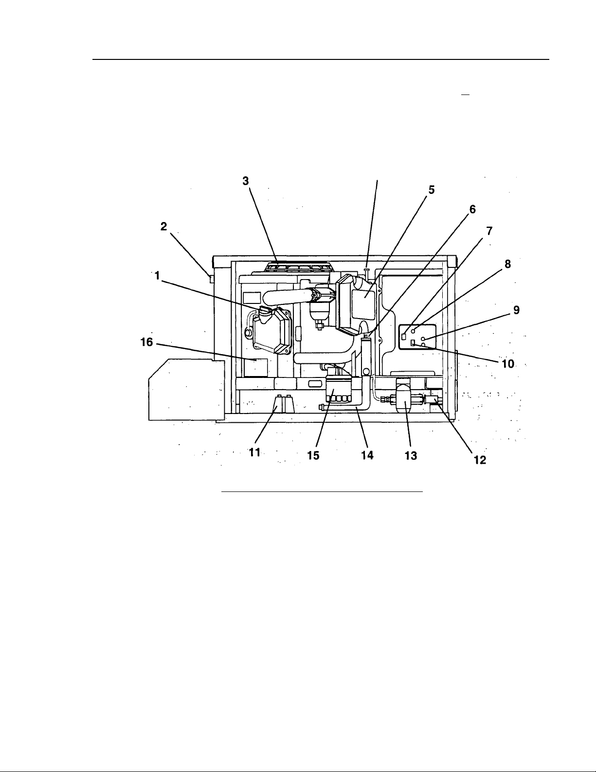
1. Oil Filler Cap , .
2. Optional Remote Panel-Receptacle
3. Generator Air Intake Screen
4. . Winter/Summer Heat .Riser.
5.‘Air Cleaner . ' ^
6. Oil Dipstick
7. Engine Start/Stop Switch
8. Fuse
9. Circuit Breakers
REFERENCE NUMBER IDENTIFICATION
10. Fuel Primer Switch
11. Starter Contactor
12. Fuel Inlet
■■ ■. • ’ I.
.V. .
— 1
13. Fuel Pump
14. Oil Drain Hose
15. Oil Filter
16. Data Decal
17. Generator AC output leads (on rear, not shown)
Page 4

TABLE OF CONTENTS
OPERATING INSTRUCTIONS
GENERAL SAFETY RULES
IDENTIFICATION RECORD AND
GENERATOR FEATURES................................................................. 1
READ THIS MANUAL THOROUGHLY
Operation and Maintenance
How to Obtain Service............................................... 3
Service Dealer Location
GENERATOR FAMILIARIZATION
Generator Applicability
Safety........................................................................... 4
Generator AC Connection System
OPERATING INSTRUCTIONS
Generator Control Panel........................................... 5
Automatic Choke
Before Starting the Engine........................................ 5
Starting....................................................................... 6
Stopping the Generator............................................. 6
Applying Loads to Generator
Attention Required After Submersion..................... 6
Operation in High Grass or Brush
Operating Precautions............................................... 7
SummerAA/inter Heat Riser System
Effects of Moisture and Dirt
Do Not Overload the Generator
ENGINE PROTECTIVE DEVICES
Automatic Low Oil Pressure Shutdown
High Temperature Shutdown................................... 8
Field Boost.................................................................. 8
Over Voltage Protection............................................ 8
Engine Overspeed...................................................... 8
SPECIFICATIONS
Fuel Requirements..................................................... 9
Engine Oil Requirements.......................................... 9
Engine Specifications................................................. 9
Generator Specifications........................................... 9
MAINTENANCE
Checking Engine Oil Level
Change Engine Oil....................................................10
Change Oil Filter
Engine Air Cleaner....................................................11
Engine Spark Plug
Fuel Filter..................................................................11
Spark Arrestor Muffler
Drive Belt
Battery
..................................................................
.......................................................................
Exercising the Generator
Out of Service Protection
Return the Unit to Service after Storage
Major Service Manual
Service Dealer Location......................................3 & 12
.......................................
inside cover
.....................................
.....................................
3&12
............................................
...........................
.......................................................
...................................
............
............
.......................
.....................................
...............................
..................
......................................
......................................................
...................................................
...........................................
.........................................
.........................................
................
.............................................
6
10
10
11
11
11
12
12
12
12
12
INSTALLATION INSTRUCTIONS
INSTALLATION SAFETY RULES
GENERAL INSTALLATION INFORMATION
Purpose and Scope.......................................................14
Safety
............................................................................
Standards Booklets..................................................... 14
3
Equipment Description
Engine-Generator Operating Speed
Generator AC Connection System.............................14
LOCATION AND SUPPORT
4
Generator Location
Generator Support
.....................................................
......................................................
Suspended Mounting...................................................15
4
Generator Restraint
GENERATOR COMPARTMENTS
....................................................
Compartment Seams
5
Compartment Size
.......................................................
Compartment Construction
Sound Insulating Materials
Acoustics.......................................................................18
6
7
7
7
8
Compartment Floor Cutouts.................................18-19
COOLING AND VENTILATION AIR
Generator Air Flow
.....................................................
Cooling Air Inlet Openings...................................20-21
Compensating for Restrictions
Testing the Installation
GASOLINE FUEL SYSTEM..............................................................22
EXHAUST SYSTEM...........................................................................23
ELECTRICAL CONNECTIONS
Electrical Junction Box...............................................24
Wiring...........................................................................24
Generator AC Connections.........................................24
Conduit....................................................................24-25
Isolating Different Power Sources
Power Supply Cord
.....................................................
Ground Fault Circuit Interrupters............................25
BATTERY INSTALLATION............................................................. 27
OPTIONAL ACCESSORIES.............................................................28
POST INSTALLATION TESTS
INSTALLATION CHECK LIST.........................................................30
MAJOR FEATURES AND DIMENSIONS...................................31
TROUBLESHOOTING
ELECTRICAL DATA...........................................................................33
REPAIR PARTS............................................................................34-45
NOTES...........................................................................................46-47
CALIFORNIA EMISSIONS WARRANTY...............................48-49
WARRANTY......................................................
......................................................................
...................................................
...............................................
..........................
...................................................
.......................................
........................................
..................................
...............................................
.............................
.......................................................
..................
back page
13
14
14
14
15
15
16
16
17
17
17
20
21
21
25
25
29
32
— 2-
Page 5

READ THIS MANUAL THOROUGHLY
If you don't understand any portion of this manual,
contact Generac for a demonstration of actual start
ing, operating and servicing procedures.
Throughout this publication and on decals affixed to
the generator, DANGER, WARNING, CAUTION and
NOTES are used to alert you to special instructions
about a particular operation that may be hazardous if
performed incorrectly or carelessly. Observe them
carefully.
These safety warnings cannot eliminate the hazards
that they indicate. Strict compliance with the special
instructions while performing the service plus "com
mon sense" are major measures to prevent acci
dents.
The following definitions apply to DANGER, WARN
ING, CAUTION and NOTES found throughout the
manual.
DANGER; After this heading you can read han
dling, installing, operating or servicing instruc
tions that, if not strictiy complied with, will result
in personal injury.
WARNING: After this heading you can read han
dling, installing, operating or servicing instruc
tions that, if not strictly complied with, may result
in personal injury.
CAUTION: After this heading you can read instruc
tions for handling, installing, operating or servic
ing the generator that, if not strictly complied with,
may result in damage to equipment and/or proper
ty-
NOTE; After this heading you can read explanatory
statements that require special emphasis.
These symbols indicate the following;
Points out important safety information and, if not
followed, could endanger personal safety and/or
property of yourself and others.
Potential explosion hazard
Potential fire hazard
A
Potential electrical shock hazard
A
The operator (driver) is responsible for proper and
safe use of the vehicle, equipment on the vehicle, and
the safety of all vehicle occupants. We strongly rec
ommend that the operator read this Owner's Manual
and thoroughly understand all instructions before
using this equipment. We also strongly recommend
instructing other occupants in the vehicle to properly
start and operate the generator. This prepares them if
they need to operate the equipment in an emergency.
OPERATION AND MAINTENANCE
It is the operator's responsibility to perform all safety
checks: to make sure that all maintenance for safe
operation is performed promptly; and to have the
equipment checked by an Authorized Dealer periodi
cally. Normal maintenance service and replacement
of parts are the responsibility of the Owner/Operator
and, as such, are not considered defects in materials
or workmanship within the terms of the warranty.
Individual operating habits and usagé contribute to
the need for maintenance service.
Proper maintenance and care of you.r recreational
vehicle generator assures a minimum number of
problems and keeps-your operating expenses at à
minimum. See your authorized -Dealer/Distributor for
service aids and accessories.
HOW TO OBTAIN SERVICE
When your RV generator set-requires servicing or
repairs, simply contact an Authorized Service Facility
for assistance. Service technicians are factorytrained and are capable of handling all of your service
needs. . : , ,
When contacting an Authorized Service Facility or the
factory about parts and’ service, always supply the
complete model number and sérial humber of your
unit as given on its data decal.
The warranty on your generator is included in this
Owner’s Manual, as well as listings for repair parts.
SERVICE DEALER LOCATION
TO LOCATE THE NEAREST GENERAC SERVICING DEALER, PLEASE CALL OUR 800 NUMBER.
ONLY DEALER LOCATION INFORMATION CAN BE OBTAINED AT THIS NUMBER.
1-800-333-1322
— 3 —
Page 6
GENERATOR FAMILIARIZATION
GENERATOR APPLICABILITY
These generators have been designed and manufac
tured for supplying electrical power tor recreational
vehicles. You should not modify the generator or use
it for any application other than for what it was
designed. If there are questions pertaining to its
application, write or call the factory. Do not use the
unit until you have been advised by a competent
authority.
DANGER; For fire safety, the generator must have
been properly installed in compliance with (1)
A
ANSI 119.2-1975/NFPA 501C-1974 "STANDARD
FOR RECREATIONAL VEHICLES", PART III,
"INSTALLATION OF ELECTRICAL SYSTEMS." The
generator also must have been installed in strict
compliance with the manufacturer’s detailed instal
lation instructions. After installation, do nothing
that might render the unit in non-compliance with
such codes, standards and instructions.
You can use this generator to supply electrical power
for operating 120 volt, single phase, 60 Hertz, electri
cal loads. These loads can require up to 5500 watts
(5.5 kW)of power, but cannot exceed 46.0 AC
amperes at 120 volts.
SAFETY
Before using the generator set, carefully read GEN
ERAL SAFETY RULES inside the cover. Comply with
these RULES to prevent accidents and damage to
equipment and/or property. Generac suggests copy
ing and posting the GENERAL SAFETY RULES in
potential hazard areas of the recreational vehicle.
Safety should be stressed to all operators of this
equipment.
GENERATOR AC
CONNECTION SYSTEM
This air-cooled QP Series generator set is equipped
with dual stator AC power windings. These two stator
windings supply electrical power to customer electri
cal loads by means of a dual 2-wire connection sys
tem.
The generators have been installed so that units only
power 120 volt AC loads (Figure 1).
Figure 1 — Connection for 120 Volts Only
CAUTION: Do not overload the generator. Some
installations may require that electrical loads be
alternated to avoid overloading. Applying exces
sively high electrical loads may damage the gener
ator and may shorten its life. Add up the rated
watts of all electrical lighting, appliance, tool and
motor loads the generator will power at one time.
This total should not be greater than the wattage
capacity of the generator. If an electrical device
nameplate gives only volts and amps, multiply
volts times amps to obtain watts (volts x amps =
watts). Some electric motors require more watts
of power (or amps of current) for starting than for
continuous operation.
QROUNDEO
NEJTRAL
-4-
Page 7
OPERATING INSTRUCTIONS
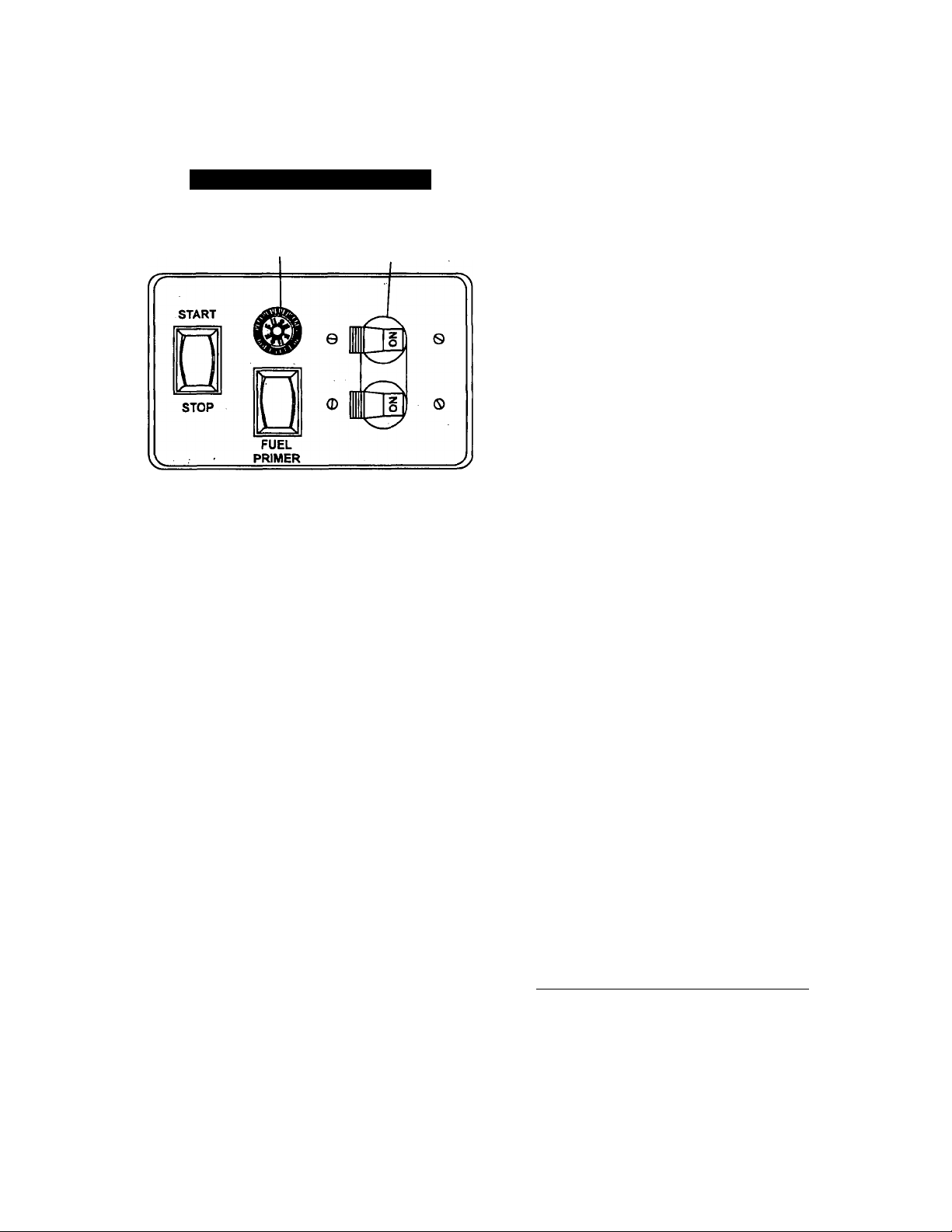
GENERATOR CONTROL PANEL
Mounted on the generator control panel (Figure 2) are
the following features:
Figure 2 — Typical Control Panel
FUSE
FUEL PRIMER
Before starting a cold engine (it has not been started
in more than two weeks), you must press this switch
to bring fuel from the tank to the carburetor. This-rock
er type switch springs back to its original position
when you release it. ..
START/STOP SWITCH
To crank and start the. engine, hold this-switch at its
START position. Release the switch when the engine
starts. To .stop an operating engine,, press and hold
the switch in its STOP position' until the engine.shuts
off. The switch center position is the RUN position.
FUSE
Protects the engine DC control circuit against electrical
overload'. If the fuse element has melted open due to
overloading, the engine cannot be cranked. If you must
replace it, use only ari identical replacement fuse.
CIRCUIT BREAKERS
Protects generator's AC output circuit against over
load, i.e., prevents unit from exceeding
wattage/amperage capacity.
CIRCUIT
BREAKERS
CHOKE SOLENOID
During engine cranking (start/stop switch at START),
a solid state choke module signals the choke solenoid
to actuate and cycle (choke on/choke off) until engine
starts. The choke solenoid thus opens and closes the
carburetor choke valve only when the engine is crank
ing. When engine starts, the choke cycling stops. .
PRECHOKE
The choke system also has a temperature sensitive
metal strip that adjusts the choke valve angle accord
ing to ambient temperatures (i.e., in cold ambient
temperatures the choke-valve closes more). Once the
engine starts, an element .heats the temperature sen
sitive strip to a normal operating condition, opening
the choke valve system. This may take about three
minutes in cooler weather.
BEFORE STARTING THE ENGINE
IMPORTANT: Instructions and information in this
manual assume the generator has been properly
installed, connected, serviced, tested and adjusted by
a qualified installation technician or installation con
tractor.
INSTALLATION
Generator installation .must have been properly com
pleted so. it complies with-all applicable codes,, stan
dards and regulations and with the manufacturer's
recommendations. . '
ENGINE LUBRICATION
: Have engine crankcase properly serviced with recom
mended oil before starting. Refer to "Maintenance"
and "Specifications" sections for. oil servicing proce
dures and recommendations.
CAUTION: Any attempt to crank or istart the
engine before you have properly serviced it with
the recommended oil may result in engine faiiure.
FUEL SUPPLY
The engine must have adequate supply of proper fuel
to operate. Before starting, check that sufficient fuel is
available.
NOTE: On some installations, thè generator engine
may “share" the vehicle’s gasoline fuel tank with the
vehicle engine. Some installations may provide sepa
rate fuel tanks for generator and vehicle engine.
AUTOMATIC CHOKE
The engine is' equipped with an automatic choke that
consists of two main components — choke solenoid
and prechoke.
-5-
■ COOLING AND VENTILATING AIR
Air inlet and outlet openings in the generator compart
ment must be open and unobstructed for continued
proper operation. Without sufficient cooling and venti
lating air flow, the engine-generator quickly overheats,
which causes it to quickly shutdown. Overheating
could also damage the unit or your vehicle.
Page 8

ENGINE EXHAUST GAS
Before starting the generator engine, you should be
sure there is no way for exhaust gases to enter the
vehicle interior and endangering people or animals.
Close windows, doors and other openings in the vehi
cle that, if open, might permit exhaust gases to enter
the vehicle.
DANGER; The generator engine gives of deadly
carbon monoxide gas through its exhaust system.
This dangerous gas, if breathed in sufficient con
centrations, can cause unconsciousness or even
death. Do NOT operate the generator if its exhaust
system is leaking or has been damaged.
Symptoms of carbon monoxide poisoning are (A)
inability to think coherently, (B) vomiting, (C)
twitching muscles, (D) throbbing temples, (E) dizzi
ness, (F) headache, (G) weakness and sleepiness.
If you feel any of these symptoms, move into fresh
air immediately. If symptoms persist, get medical
help.
STARTING
IMPORTANT; Read the vehicle manufacturer’s
instructions. The owner/operator should become
familiar with the vehicle in which this generator is
installed. Differences exist between vehicles. For
example, some vehicles may use a transfer switch to
isolate dockside power from the generator, while
other vehicles may use an isolating receptacle. Some
vehicles may be equipped with a DC converter which
allows the generator to power certain DC lighting and
other DC loads.
To crank and start the generator engine, proceed as
follows;
TTurn OFF electrical loads, using whatever means provid
ed in your vehicle (such as a main line circuit breaker or
transfer switch).
NOTE: If you start the engine with the start/stop
switch on the generator control panel, turn OFF loads
by setting the panel’s circuit breakers to their “OFF” or
“OPEN” position. Electrical load circuits can be turned
ON after the generator has started, stabilized and
warmed up.
NOTE: You only need to use the fuel primer during
the initial startup, after the unit has not been used for
an extended period of time (two weeks) or the fuel
line has been disconnected. The primer is used to
prime fuel pump and carburetor.
2. To crank and start the engine, hold the start/stop switch
at START. Release the switch when the engine starts.
CAUTION: If the engine does not start after it has
been cranking for 15 seconds, release the start/stop
switch and try again. Holding the switch for longer
than 15 seconds may damage the starter motor.
3. Let the engine run at no-load for a few minutes to stabi
lize and warm up the engine.
4. Turn ON electrical loads, using whatever means provided
(such as a main circuit breaker or transfer switch).
NOTE: If you start a warm generator engine, you
may press the start switch only slightly to engage the
ignition system. However, you should press and hold
the starter switch for a minimum of two (2) seconds to
energize the field boost system. If yqu start the
engine without energizing the field boost system, the
generator produces no AC output.
STOPPING THE GENERATOR
1. Turn OFF all electrical loads, using whatever means pro
vided (such a main circuit breaker or transfer switch).
2. Let the generator run at no-load for a few minutes, to sta
bilize internal engine-generator temperatures.
3. Hold Start/Stop switch in its STOP position until engine
comes to a stop.
APPLYING LOADS TO GENERATOR
When applying electrical loads to the generator,
observe these guidelines:
• Before applying electrical loads, let the generator stabilize
and warm up for a minute or two.
• DO NOT overload the generator.
■ LEniNG ENGINE STABILIZE
The generator supplies correctly rated frequency and
voltage only at the proper governed speed. Some
electrical appliances may be extremely sensitive to
voltage and frequency. Incorrect frequencies and/or
voltages can damage those appliances.
If electrical loads are applied at reduced operating
speeds, such loads imposed on the engine when suf
ficient power is not available may shorten engine life.
Never turn ON electrical loads until after the genera
tor engine has started and stabilized ON-speed.
AHENTION REQUIRED AFTER
SUBMERSION
If the recreational vehicle generator has been sub
merged in water, it must NOT be started or operated.
Following any submersion in water, have an autho
rized Generac Service Facility thoroughly clean and
dry the generator.
OPERAHON IN HIGH GRASS OR BRUSH
~T Never operate the generator while the vehicle
is parked in high grass, weeds, brush or
¿SzA leaves. Such materials can ignite and burn
^ from the heat of the exhaust system. The gen
erator exhaust system becomes extremely hot
during operation and remains hot for a long
time after it has shut down.
— 6
Page 9
OPERATING PRECAUTIONS
Never operate the recreational vehicle genera
tor set while the vehicle is parked over dry
A
leaves, dry grass or any other combustible
substance. The generator's exhaust system
becomes extremely hot and can cause fire it it
is too close to combustible materials.
The generator’s exhaust system gives off
DEADLY carbon monoxide gas. This danger
ous gas, if breathed in sufficient concentra
tions, can cause unconsciousness and even
death. Never operate the generator set with
the vehicle inside any garage or other
enclosed area. Never operate the generator if
it has a leaky exhaust system. Close windows
in the vicinity of the generator exhaust outlet
and take any other steps to prevent exhaust
gases from entering rooms or areas occupied
by people or animals. .
SUMMER/WINTER HEAT RISER
SYSTEM
Under certain weather conditions, it is possible for ice
to form in the venturi area of the carburetor. This con
dition can be very dangerous because it can prevent
the governor system from functioning properly, which
results in a “run-away” engine.
The most common weather-conditions leading to this
problem are temperatures in the range of 25° to 35°F,
along with high humidity. This ice formation can also
be attributed to the load being applied during these
weather conditions. Generators running with no load
or light loads applied usually have the most problems.
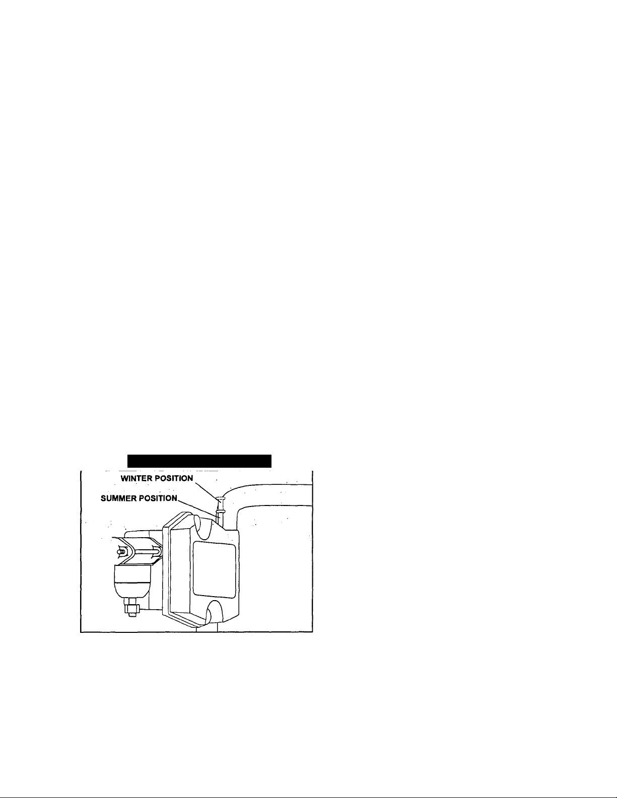
The SummerA/Vinter Lever (Figure 3) should be in the
WINTER position for ambient teniperatures below
40°F and in the SUMMER position for arnbieht tem
peratures above 40°F.
Figure 3 — Heat Riser System
When the heat riser is in the SUMMER (DOWN) posi
tion (Figure 3), air is drawn into the air cleaner from
the upper intake tube.
When the heat riser is in the WINTER (UP) position,
air is drawn from the lower intake tube, which is posi
tioned to draw the heated air near the exhaust mani
fold.
To prevent carburetor icing the owner/operator should
physically position the heat riser to the proper position
dependent on the temperature.
EFFECTS OF MOISTURE AND DIRT
Keep the generator set as clean and dry as possible.
Protect unit against excessive dust, dirt, corrosive
vapors, road splash, etc. Permitting dirt and moisture
to accumulate on generator windings will have an
adverse effect on the insulation resistance of those
windings.
When moisture is allowed to remain in contact with
windings, some of the moisture will be retained in
voids and cracks, in the insulation. This causes a
reduced insulation resistance and will eventually
cause problems. Dirt will make the problem worse,
since dirt tends to hold moisture in contact with wind
ings. Salt (as from sea air) will also worsen the prob
lem since it tends to absorb moisture from the air.
Salt and moisture, when combined, form a good elec
trical conductor.
CAUTION! Do NOT use a forceful spray of water to clean
the generator. Water will enter the generator interior and
cause problems, and may also contaminate the generator
fuel system.
DO NOT OVERLOAD THE
GENERATOR
You can read the rated wattage/amperage,capacity of.
your generator,on the generator data decal (see
“Identification Record” on Page 1). .
Applying electrical loads ,iri excess of the unit’s rated
capacity will cause-the engine-generator to discon
nect the AC output.
To avoid overloading, add. up the wattage of all conhected electrical lighting, appliance, tool and motor
loads. This total should not be greater than thé gener
ator’s rated wattage capacity.
• Most lighting, appliance, tool and motor loads indicate
their required watts on their nameplate or data plate. For
light bulbs, simply noté the wattage rating of the bulb. '
• If a load does not show its rated wattage, multiply that
load’s rated VOLTS times AMPS to obtain WATTS.
• Induction type motors (such as those that run the vehicle’s
furnace fan, refrigerator, air conditioner, etc.) need about 2-
i/2 times more watts of power for starting than for running
(for a few seconds during motor starting). Be sure to allow
for this when connecting electrical loads to the generator.
First, figure the watts needed to start electric motors in the
system. To that figure, add the running wattages of other
items that will be operated by the generator.
• On a new generator do not apply heavy electrical loads
for the first two or three hours of operation.
-7-
Page 10
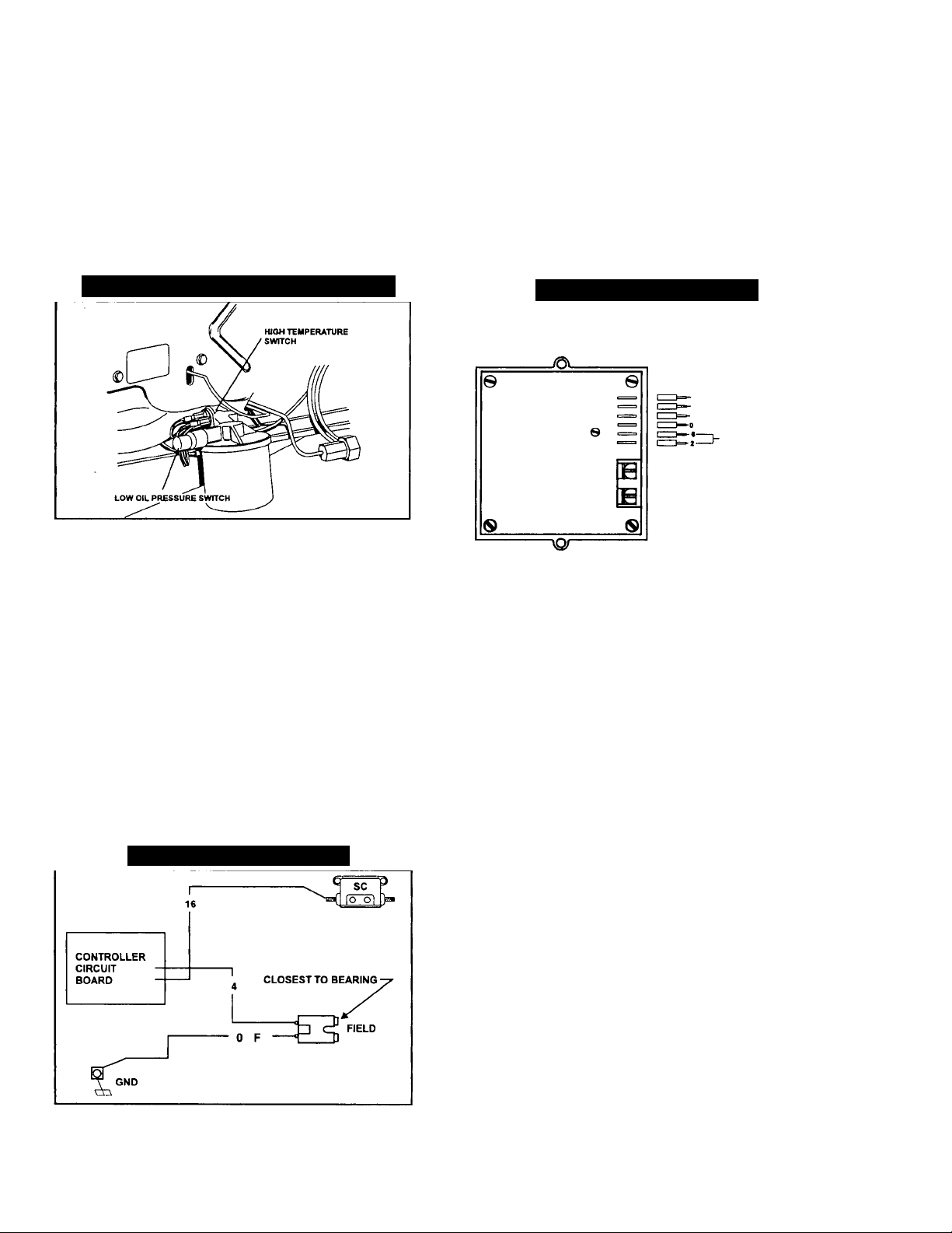
ENGINE PROTECTIVE DEVICES
AUTOMATIC LOW OIL
PRESSURE SHUTDOWN
The engine is equipped with a normally closed (N.C.)
oil pressure switch (Figure 4).Engine oil pressure
holds the switch open during cranking and operation.
Should oil pressure drop below about 7.5-12 PSI, the
switch contacts close and the engine automatically
shuts down.
Figure 4 — Switches for Engine Shutdown
HIGH TEMPERATURE SHUTDOWN
A temperature switch (Figure 4) with normally closed
(N.C.) contacts is mounted near the oil filter. If the
temperature were to exceed about 284°F (140°C), the
switch contacts close and the engine shuts down.
FIELD BOOST
The Controller Circuit Board houses a field boost
diode and resistor which are not part of the automatic
choke circuit. These two components are part of a
“field boost” circuit (Figure 5). During engine cranking
only, a positive DC (battery) voltage Is delivered
through the diode, resistor, brushes and slip rings,
and to the generator rotor. Application of this voltage
to the rotor “flashes the field” whenever it is started.
Flashing of the field each time the generator is started
makes sure that a sufficiently strong magnetic field is
available to produce the required “pick up” voltage in
the stator windings.
Figure 5 — Field Boost Circuit
OVER VOLTAGE PROTEaiON
A solid state voltage regulator (Figure 6) controls the
generator’s AC output voltage. This regulator controls
an excitation current to the rotor. By regulating the
rotor’s excitation current, the strength of its magnetic
field is regulated and, in turn, the voltage delivered to
connected electrical loads is controlled. When the AC
frequency Is 60 Hz, voltage is regulated at 120 volts
(voltage-to-frequency ratio is 2-to-1).
Figure 6 — Voltage Regulator
„ ~V- SENSING
11—'
TO ROTOR
(.) —1~ (DIRECT CURRENT)
FROM STATOR
EXCnATIONWINDMO
(ALTERNATING CURRENT)
The voltage regulator also incorporates a “voltage
surge protection circuit.” This circuit prevents trouble
some surges in the generator AC output voltage.
Voltage surge is a common cause of damage to elec
tronic equipment.
ENGINE OVERSPEED
If engine speed is increased manually or otherwise,
the circuit controller board will disable the system and
shut down the engine.
WARNING: Do NOT attempt to physically adjust or
control the engine speed. Equipment damage or
personal injury may result.
Page 11

SPECIFICATIONS
FUEL REQUIREMENTS
This generator is equipped with a gasoline fuel sys
tem as standard equipment. Specific installations may
provide either a separate fuel tank for the generator,
or the generator may “share” the vehicle engine’s fuel
tank.
NOTE: Installations using a “shared” fuel tank may
have a generator fuel pickup tube that is shorter than
the vehicle engine’s pickup tube. Such an arrange
ment causes the generator engine to “run but of gas”
while adequate fuel for the vehicle remains in the
tank.
To reduce lead and carbon deposits use high quality
UNLEADED gasoline with the generator. Leaded
REGULAR grade gasoline is an acceptable substi
tute.
NOTE: Using “Unleaded” gasoline contributes to
longer engine valve life by reducing lead and carbon
deposits.
CAUTION: Generac does not recommend using
any gasoline containing alcohol, it must not con
tain more than 10 percent ethanoi and it must be
removed from the tank during storage. Do NOT
use any gasoline containing methanol. If you use
gasoline with alcohol, inspect more frequently for
fuel leaks and other abnormalities.
ENGINE OIL REQUIREMENTS
Use only high quality detergent oil rated with API ser
vice classification SF, SG or SH. The recommended
oil weights include the following:
• During summer months: SAE 30. An. acceptable substi-
. tuteisSAE10W-30.
• During winter months: SAE 5W30. DO NOT USE SAE
10W-40.
Crankcase and oil filter capacity is about 1400ml or
about 1.5 U.S. quart. Use no special additives. See
“Maintenance” section for oil level check and fill pro
cedures.
ENGINE SPECIFICATIONS
Type of Engine
Cooling Method
Rated Horsepower
Displacement
Cylinder Block
Engine RPM
Type of Governor
Air Cleaner
Starter
Ignition System
Recommended Spark Plug
Spark Plug Gap
..........................................
Champion
AC:
...........................................
Autolite
.........................
.......................
......................
...............................
............................
................................
........................
..................................
........
............
................ ............
..........................
...........................
...........
'.GN-410, single-cylinder
...Air-cooled
14.5 at 3600 rpm
410cc
Aluminum with cast
iron sleeve
2571-2830
Electronic
Paper element with
foam pre-cleaner
12 volt DC electric
......
Solid state with
flywheel magneto
...RC12YC
R45S
65
0.030 inch (0.76mm)
GENERATOR SPECIFICATIONS
Rotor RPM
Rotor Poles
Rated Maximum Continuous
AG Power Output...'
Rated Voltage
Rated Maximum Continuous
Current at 120 volts
Phase
Rated AC Frequency
Weight (w/oil)
Width
Length............................................32.5 inches (825mm)
Height
Maximum Battery
Circuit Current;...
Recommended Battery
Cranking Current...........................................400AMPS
Battery Charge Current
Battery Charge Voltage
Fuel Consumption:
..............................................................
.........................................................
......................
...... ................................
.................
..........-.....
...........................................
............................................
.'.
....
,....-
........................
.................... ...........
.......... ................
.........
................................... 15 AMPS
.................................................
.................................
5500 watts (5.5 kW)
..........
'....■.271- pounds (93 kg)
.20.5 inches (520mm)
17.4 inches (442mm)
3600
............2
120 volts AC
46.0 AC amperes
...Single Phase
............60 Hz.
14 VOLTS
2 AMPS
LOAD
NO
HALF
FULL 0.77
GALLONS/HOUR
0.29
0.53
Page 12
MAINTENANCE
This section includes information about simple main
tenance which includes the following tasks;
• Checking the engine oil level.
• Changing the engine oil.
• Changing the oil filter.
• Cleaning the air cleaner.
• Cleaning the spark plug.
• Changing the fuel filter.
• Cleaning the spark arrestor
• Servicing the drive belt.
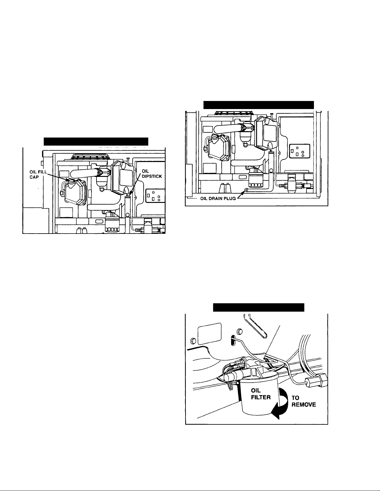
Figure 7 — Oil Dipstick and Fill Cap
CHECKING ENGINE OIL LEVEL
Check engine crankcase oil level at least every eight
hours of operation, or before each use (Figure 7).
• Be sure the generator is as level as possible.
• Remove oil dipstick and wipe dry with clean, lint-free
cloth.
• Install and tighten oil dipstick, then remove again.
• Oil level should be within the cross-hatched area on the
dipstick. If necessary, remove oil fill cap and add the rec
ommended oil to the cross-hatched area only. DO NOT
FILL ABOVE CROSS-HATCHED AREA.
• Install and tighten oil dipstick and oil fill cap before oper
ating the engine.
NOTE: See “Engine Oil Requirements” on Page 9 for
recommended oils.
When oil has drained, install and tighten oil drain plug.
Remove oil fill cap (Figure 7) and fill crankcase with the
recommended oil (See Page 9). The engine crankcase
can hold about 1.5 U.S. quarts (1.6 liters). DO NOT FILL
ABOVE THE CROSS-HATCHED AREA.
Install and tighten oil fill cap before operating engine.
Figure 8 — Location of Oil Drain Plug
CHANGE OIL FILTER
Replace the engine oil filter after the first 25 hours of
operation, every 100 operating hours thereafter.
• Turn oil filter counterclockwise to remove (Figure 9).
• Coat gasket of new filter with engine oil.
• Turn new filter clockwise until its gasket contacts lightly
with the filter adapter. Then tighten an additional 3/4 to
one turn.
• Run engine and check for leaks.
NOTE: Check the oil level and fill to the cross-hatched
area on dipstick after checking for leaks. The filter will
retain some oil.
Figure 9 — Replacing Oil Filter
CHANGE ENGINE OIL
Change engine oil after the first 25 hours of operation.
Thereafter, change oil every 50 operating hours.
Change oil more frequently if operating consistently
under heavy load or at high ambient temperatures.
• Warm up engine for at least five minutes, then shut down.
• With engine still warm from running, remove oil drain plug
(Figure 8). Drain oil completely into a suitable container.
— 10 —
Page 13
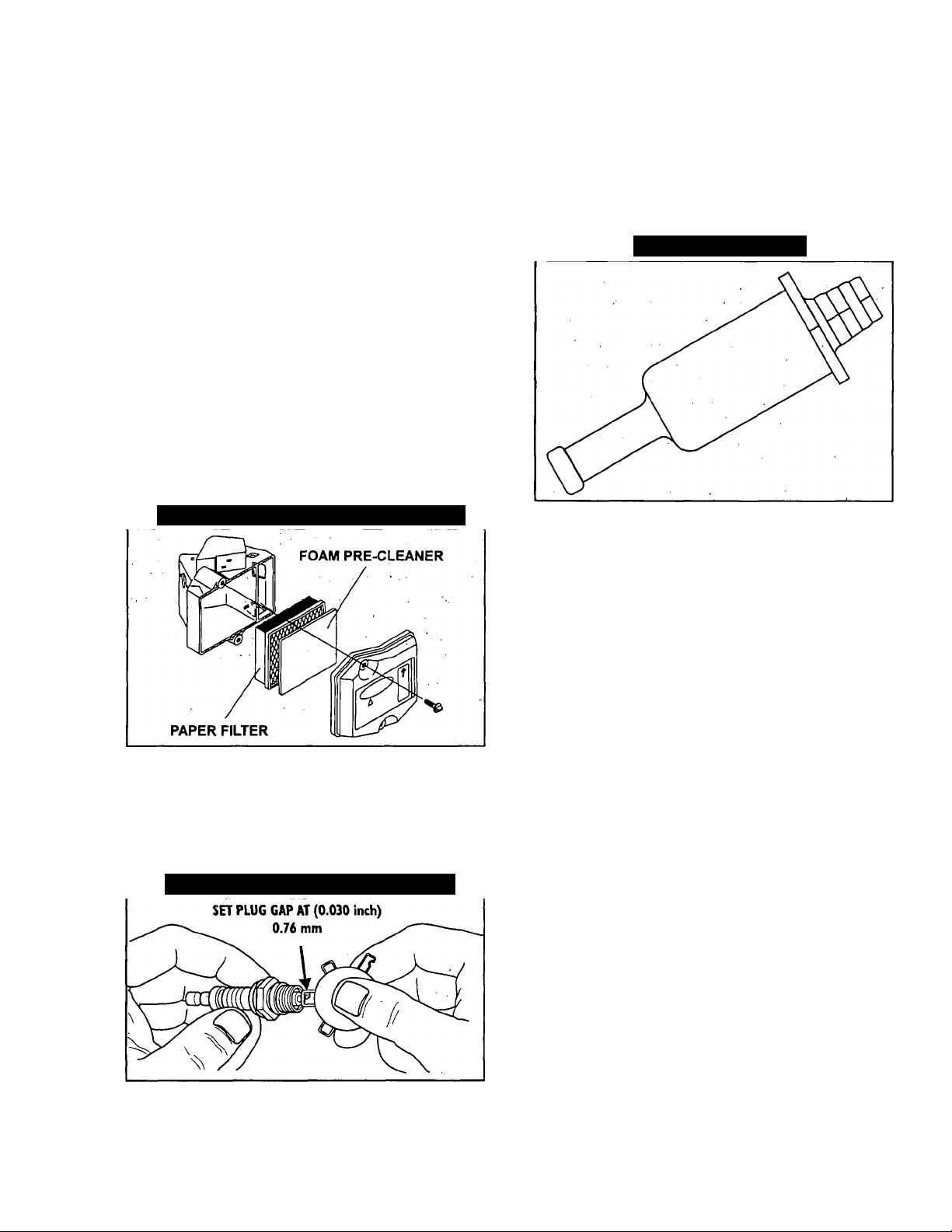
ENGINE AIR CLEANER
Clean and re-oil the foam pre-cleaner every three
months or every 25 hours of operation, whichever
occurs first. Service the foam pre-cleaner more frequently
if you operate the generator in extremely dusty or dirty con
ditions (Figure 10).
• Turn the two screws counterclockwise to loosen.
• Remove COVER, FOAM PRE-CLEANER and PAPER
FILTER.
• Remove foam pre-cieaner from cover.
• Vt/ash foam pre-cleaner in liquid detergent and water.
• Wrap foam pre-cleaner in a cloth and squeeze dry.
• Saturate foam pre-cleaner in engine oil. Squeeze to
remove excess oil and distribute oil (DO NOT TWIST).-
• Install foam pre-cleaner into cover, followed by paper fil
ter.
• Install cover, foam pre-cleaner and paper filter.
• Tighten the two screws to retain filter in place.
Once each year or every 100 operating hours
(whichever comes first), replace the paper filter. The
new replacement filter must be a flame retardant type.
Figure 10 — Engine Air Cleaner Assembly
CAUTION; Sparking can occur if wire terminal
does not fit firmly over spark plug terminal end. If
necessary, reform wire terminal to obtain a tight fit.
FUEL FILTER
Remove and replace fuel filter (Figure 12) every 100
operating hours or once each year, whichever comes
first.
Figure 12 — Fuel Filter
ENGINE SPARK PLUG
Clean or replace engine spark plug and set gap to
0.030 inch (0.76mm) every 100 hours of operation
(Figure 11). Clean by scraping or wire brushing and
washing with commercial solvent. DO NOT BLAST
CLEAN SPARK PLUG.
Figure 11 — Setting Gap on Spark Plug
SPARK ARRESTOR MUFFLER
Exhaust mufflers supplied by Generac are spark
arrestor types. Generac exhaust mufflers for RV gen
erators do not have a spark arrestor screen, but are
of the more efficient “tproid" or “swirl” type. To remove
carbon and combustion deposits from such mufflers,
remove the PLUG from muffler and run engine for
about 15 minutes. Shut engine down, let the muffler
cool and install the plug.
WARNING: Be sure to re-install the plug from the
muffler tightly. Engine vibration could cause a
loose plug to fall out. Without the plug in place,
hot engine exhaust is directed out the opening.
This hot exhaust, depending on the installation,
could be directed to areas not able to withstand
the extreme heat, such as wooden floor boards or
other flammable materials. This could result in a
fire.
DRIVE BELT
The engine drives the generator rotor by means of a
pulley and drive belt arrangement. The drive belt and
pulleys are warranted for the life of the generator.
Drive belt tension was properly adjusted before the
unit was shipped from the factory. If you suspect that
drive belt tension is incorrect, contact an authorized
service facility.
—11 —
Page 14

BATTERY
All lead-acid storage batteries will discharge when not
in use. Inspect the generator battery as follows:
Once Weekly: Inspect battery posts and cables for
tightness, corrosion. Clean and/or tighten as needed.
Also check battery fluid level, and, if necessary, fill
with DISTILLED WATER ONLY. DO NOT USE TAP
WATER IN BATTERY.
Every Six Months; Have the battery state of charge
and condition checked by an automotive service facili
ty. This should be done with an automotive type bat
tery hydrometer.
DANGER: Storage batteries give off expiosive
hydrogen gas. This gas can form an expiosive mix
ture around the battery for several hours after
charging. The slightest spark can ignite the gas
and cause an explosion. Such an explosion can
shatter the battery and cause blindness or other
injury. Any area that houses a storage battery
must be properly ventilated. Do not allow smoking,
open flame, sparks or any spark producing tools
or equipment near the battery.
DANGER: Battery electrolyte fluid is an extremely
caustic sulfuric acid solution that can cause
severe bums. Do not permit fluid to contact eyes,
skin, clothing, painted surfaces, etc. Wear protec
tive goggles, protective clothing and gloves when
handling a battery. If you spill the fluid, flush the
affected area immediately with clear water.
DANGER: Do not use any jumper cables or boost
er battery to crank and start the generator engine.
If any battery has discharged, remove it from the
vehicle for recharging.
EXERCISING THE GENERATOR
Generac recommends that you start and operate the
generator at least once every seven days. Let the unit
run for at least 30 minutes to “exercise" the engine.
OUT OF SERVICE PROTECTION
If you cannot exercise the generator every seven
days and it is to be out of service longer than 30 days,
prepare the generator for storage as follows;
• Start the engine and let it warm up.
• Close the fuel shutoff valve in the fuel supply line and let
the engine “run out of fuel."
• While the engine is still warm from running, drain the oil
completely. Refill crankcase with the required oil. See
Page 9 for engine oil requirements.
• Attach a tag to the engine indicating the viscosity and
classification of the oil in the crankcase.
• Remove spark plug and add about 1/2 ounce (15ml) of
clean, fresh engine oil into spark plug threaded opening.
Crank engine several times to distribute oil, then install
and tighten spark plug.
• Remove the battery and store in a cool, dry room on a
wooden board. Never store the battery on any concrete
or earthen floor.
• Clean and wipe the entire generator.
RETURN UNIT TO SERVICE
AFTER STORAGE
To return the unit to service after storage, proceed as
follows:
• Check tag on engine for oil viscosity and classification.
Verify that the correct recommended oil is used in engine.
If necessary, drain and refill with proper oil.
• Check battery. Fill all cells to the proper level with distilled
water. DO NOT USE TAP WATER IN THE BATTERY.
Recharge battery to 100% state of charge, or, if defective,
replace the battery.
• Turn OFF all electrical loads, turn on fuel supply. Use
primer switch to prime fuel, then start the engine.
• Let engine warm up.
• Apply electrical loads to at least 50% of the unit’s rated
wattage capacity.
• When engine is thoroughly warmed up, shut it down.
THE GENERATOR IS NOW READY FOR SERVICE.
MAJOR SERVICE MANUAL
To obtain a service manual for your generator, order it
from your dealer/distributor or contact the factory. Be
sure to identify your unit’s MODEL NUMBER and
SERIAL NUMBER.
SERVICE DEALER LOCATION
TO LOCATE THE NEAREST GENERAC SERVICING DEALER, PLEASE CALL OUR 800 NUMBER.
ONLY DEALER LOCATION INFORMATION CA BE OBTAINED AT THIS NUMBER.
1 -800-333-1322
12 —
Page 15

DANGER: For fire safety, installation of a generator into a recreational vehicle must comply
strictly with article 551, NFPA 70; ANSI C1-1975; AND, ANSI All9.2-1975/NFPA 501C
‘‘STANDARD FOR RECREATIONAL VEHICLES” (PART 3, “INSTALLATION OF ELECTRICAL
SYSTEMS"). In addition, the manufacturer’s instructions and recommendations must be
complied with.
NOTICE TO INSTALLER
The Installation Instructions have been published by
Generac Corporation to aid in the installation of the
products described in this manual. Generac assumes
that installation personnel are familiar with the proce
dures for installing such products, or similar products
that Generac manufactures. Generac also assumes
that personnel have been trained in the recommend
ed installation procedures for these products and that
such training includes (a) use of common hand tools,
(b) use of special Generac tools, and (c) use of any
tools and/or equipment from other suppliers.
We could not possibly know of and adyise the recre
ational vehicle trade of all conceivable methods, pro
cedures or techniques by which to perform an installa
tion. We could not know, of the possible hazards that
might result from each installation method, procedure
or technique. We have not undertaken any such wide
evaluation. Therefore, people who use a method, procedüre or technique that Generac does not specifically
recommend must first completely satisfy themselvès
that their safety, the safety of the vehicle's occupants
and the product's safety is not endangered by the
method, procedure or tecnnique selected.
Information, illustrations, specifications, etc., con
tained in this Installation Manual are based on the lat
est information available at the time of publication.
Every effort has beeri expended to be sure that such
data is. both accurate and current. However, the man
ufacturer reserves the right to change, alter or other
wise improve this product at any time, without prior
notice.
SAFETY RULES
Gasoline is extremely FLAMMABLE and its
vapors are EXPLOSIVE. Do not permit smoking,
open flame, sparks or any source of heat in the
vicinity while handling gasoline. Comply with all
laws governing the storage and handling of gaso
line.
Fuel lines must be properly installed, properly
fastened and free of leaks. There must be no
possibility of gasoline vapors entering vehicle
interior.
You are required to install an approved, flexible,
non-conductive fuel line between the generator
fuel connection point and rigid fuel lines.
If the generator is equipped with a liquid propane
(LP) gas fuel system, install the unit so it com
plies with all codes, standards and regulations
pertaining to such systems. LP .gas is highly
explosive. The gas tends to settle in low areas
where even the slightest spark can ignite it and
cause an explosion. Do not allow gas vapors to
enter the vehicle.
Engine exhaust gases contain DEADLY carbon
monoxide gas. This dangerous gas, if breathed in
sufficient concentrations, can cause uncon
INSTALLATION SAFETY RULES
sciousness or even death. Install the exhaust
system in strict compliance with applicable
codes, standards and regulations. There must be
no possibility for exhaust gases entering the vehi
cle interior and endangering people or animals.
A The gerierator set produces dangerously high
electrical voltage, Contact with bare wires, bare
terminals, etc., will result in extremely hazardous
and possibly lethal electrical shock.
• All applicable electrical codes, standards and
regulations must be strictly complied with in the
installation and use of this equipment.
• The generator must be properly grounded (bond
ed) to the vehicle chassis or frame.
If the vehicle electrical circuits can be powered by
A
any .other source of electricity (such as a “dockside”
power receptacle), there must be no possibility of
connecting the diferent power sources to the vehi
cle circuits at the same time. The “dockside” (utility)
power source must be positively isolated from the
vehicle circuits whenever the generator is operat
ing. Failure to isolate the vehicle circuits from the
dockside power supply when the generator is run
ning may result in damage to the generator or seri
ous injUiy or death to dockside (utility) power work
ers due to backfeed of electrical energy.
Never work on the equipment while standing in
A
water, while barefoot, or while hands or feet are
wet. Dangerous electrical shock will result.
Jewelry conducts electricity, which can cause
dangerous electrical shock. Remove all jewelry
(such as rings, watches, or bracelets) before
working on this equipment. '
Thé generator requires an adequate flow of air
for cooling and ventilation. Without sufficient cool
ing air flow, the engine-generator quickly over
heats, which causes serious damage to the gen
erator, a fire or an explosion. Generator air inlet
and outlet openings must be provided in strict
compliance with the manufacturer's recommen
dations.
Never work on this equipment while physically or
mentally fatigued. Stay alert at all times.
Storage batteries give off EXPLOSIVE hydrogen
gas wnile charging. The battery used for cranking
and starting this generator should be installed in
its own vented compartment. Provide'adequate
ventilation for the battery, to prevent explosive
hydrogen gas from accumulating.
Never.insert any tool or other object through
openings in the generator interior, even if the unit
is not running. You might seriously injure yourself
or damage the equipment.
Staying alert and using “common sense” are
major measures for preventing accidents.
— 13 —
Page 16
GENERAL INSTALLATION INFORMATION
PURPOSE AND SCOPE OF MANUAL
These Installation Instructions have been prepared
especially for the purpose of familiarizing installers
and owners of the applicable equipment with the pro
duct's installation requirements. Give serious consid
eration to all information and instructions in the manu
al, both for safety and for continued reliable operation
of the equipment.
Because of the different recreational vehicle models
and the variations between the models, it would be
extremely difficult, if not impractical, to provide
detailed instructions on every installation possibility.
For that reason, instructions and illustrations in this
manual are general in nature. Illustrations are not
intended to serve as detailed installation blueprints.
The installation should comply strictly with all applica
ble codes, standards and regulations pertaining to the
installation and use of this product. If any portion of
this manual appears to be in conflict with such codes,
standards or regulations, the applicable codes, stan
dards,or regulations must take precedence over the
manual.
SAFETY
Before handling, installing, operating or servicing this
equipment, be sure to read carefully the “Notice to
Installer” and “Safety Rules” at front of this manual.
Comply with all SAFETY RULES to prevent death,
personal injury or damage to equipment and/or prop
erty. Stress safety to all installers, operators and ser
vice technicians who work on this equipment.
EQUIPMENT DESCRIPTION
Instructions and information in this section pertain to
Generac air-cooled generators. These generators are
designed specifically for installing in recreational vehi
cles. They operate 120 volt, single phase, 60 Hertz, AC
electrical loads that require 46.0 amps at 120 volts.
ENGINE GENERATOR
OPERATING SPEED
The generator’s revolving field (rotor) is driven by a
single-cylinder, 4-cycle engine through a pulley and
drive belt arrangement. The generator supplies 120
volts AC at 60 Hertz when the rotor is operating at
3600 rpm.The drive belt arrangement allows the
engine to operate at a lower speed than the rotor.
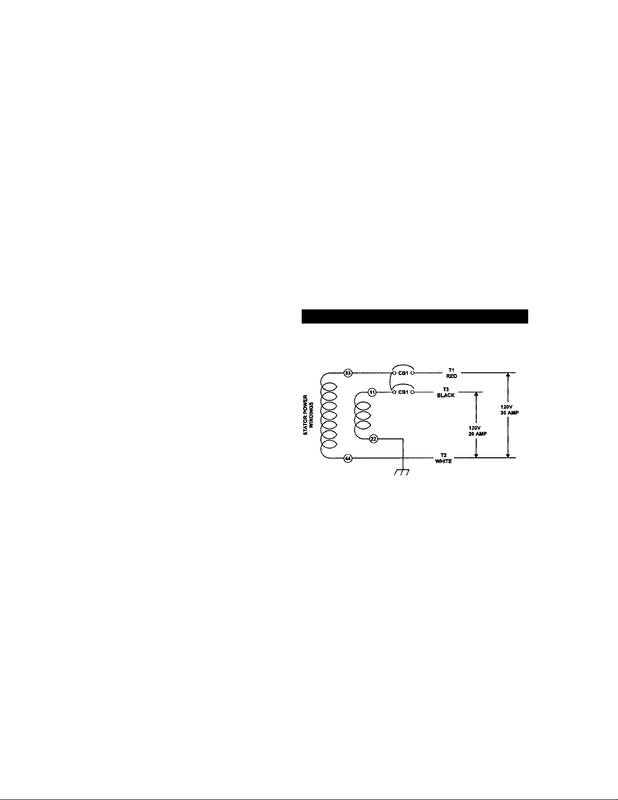
GENERATOR AC CONNECTION
SYSTEM
The generator is equipped with dual stator power
windings as shown in figure 13.
Figure 13 — 120 Volt Single Voltage Connection
STANDARDS BOOKLETS
Installation, use and servicing of this equipment
should comply strictly with published standards, as
well as the manufacturer's recommendations. The fol
lowing standards booklets (latest revision) are avail
able from the sources indicated:
1. NFPA Standard 501C, “Standard for Recreational
Vehicles”, available from the National Fire Protection
Association, Batterymarch Park, Quincy, MA 02269.
2. NFPA 70, “NFPA Handbook of the National Electric
Code”, obtained from same address as Item 1.
3. ANSI Cl-1975 and ANSI 119.2-1975, available from the
American National Standards Institute, 1430 Broadway,
New York, NY 10018.
4. ANSI A119.2/NFPA 501C, available from the
Recreational Vehicle Association, 1896 Preston White
Drive, Reston, VA 22090.
5. California Administrative Code, Title 25, available from
the State of California, Documents Section, P.O. Box
1015, North Highlands, CA 95660.
6. CSA Electrical Bulletin 946, available from the Canadian
Standards Association, Housing and Constructions
Materials Section, 178 Rexdale Boulevard, Rexdale,
Ontario, Canada, M9W 1R3.
OROUNDED
NEUTRAL
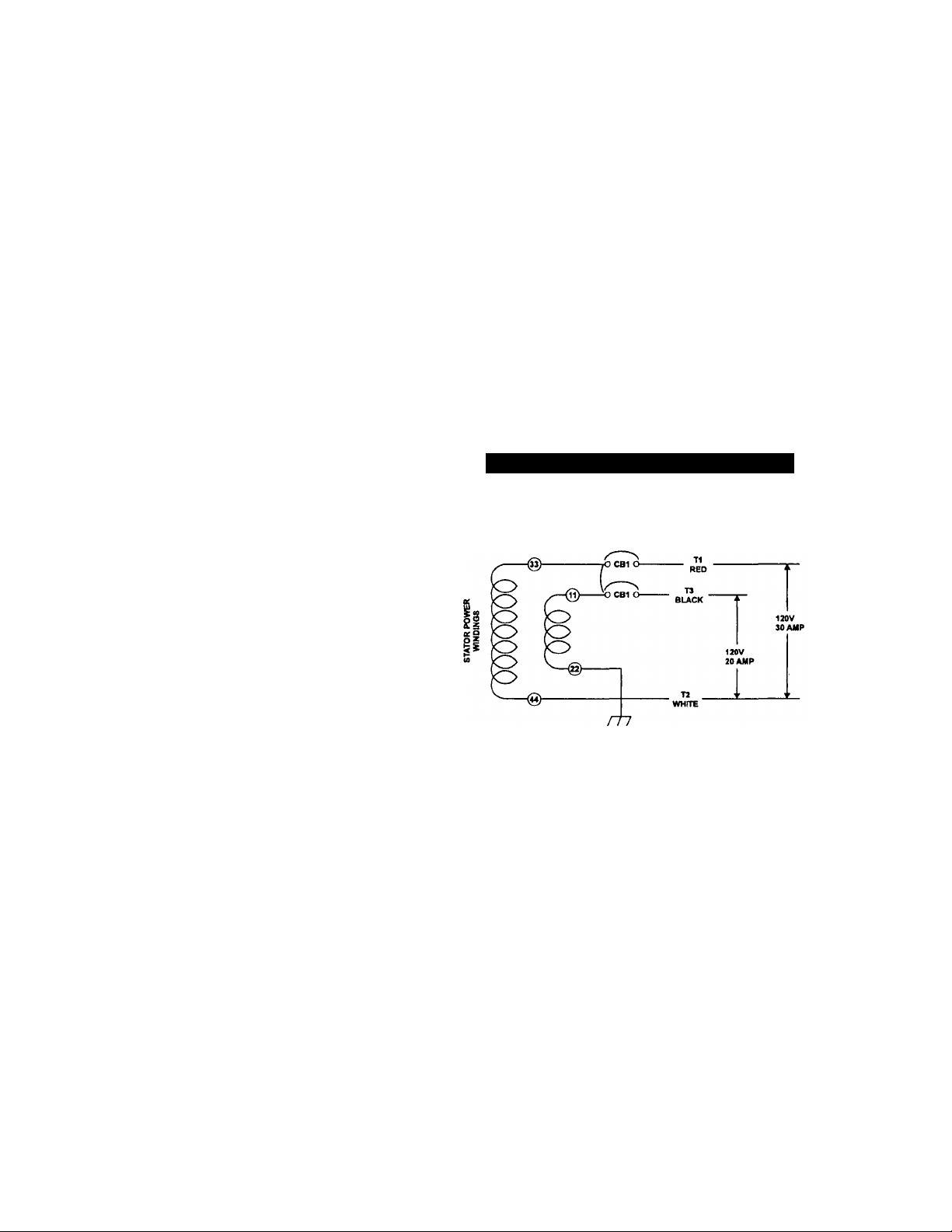
• The AC connection system on all air-cooled QP series
generators uses a GROUNDED neutral.
• A separate green ground wire is connected to the recre
ational vehicle’s junction box.
• For these QP55 units, loads connected across T1 (red) to
T2 (white), MUST NOT exceed 30 amperes or 3600 watts
and loads connected across T3 (black) and T2 (white)
MUST NOT exceed 20 amperes or 2400 watts each at
120 volts. The combined loading of the two breakers
should not exceed 5500 watts.
IMPORTANT: DO NOT CONNECT LOADS IN EXCESS OF
CIRCUIT BREAKER RATINGS.
— 14 —
Page 17

LOCATION AND SUPPORT
GENERATOR LOCATION
The most desirable location for the generator set is
between the vehicle's main frame members However,
this is seldom possible. Most ünits must be installed
on the side of the vehicle and are difficult to reinforce.
Many recreational vehicles have been factory
equipped with an area for the generator set. Some
vehicles may even have a generator compartment,
provided by the vehicle manufacturer.
Plan the generator location based on the following;
• The generator set must be installed on a framework that
is part of the recreational vehicle, as outlined in the para
graph entitled “Generator Support.”
• The location must provide an access opening that is large
enough to permit generator removal (unless the genera
tor is to be removed from underneath the supporting
framework).
• The location must provide easy access to frequently ser
viced components, such as filters,, oil drains, spark plugs
and other common maintenance parts.
• The location must provide sufficient room to allow mini
mum clearances as outlined in the “Generator
Compartments” section. If sound insulation is to be used
on compartment walls and ceiling, the minimum recom-
. mended applies to the space between the generator and
such insulation.
• The location must provide adequate cooling and ventilat
ing air flow for the generator without a great deal of work
and expense.
GENERATOR SUPPORT
The generator must be securely attached to a metal
framework that has been made part of the vehicle
frame structure by bolting or welding; The metal
framework on which the generator will rest and which
will restrain the generator set should consist of at
least two horizontal beams. These beams should con
sist of (a) 1-1/2 inch square,. li gauge steel tubing
OR (b) 1-1/2 inch, 11 gauge angle iron. A typical sup
porting frame with horizontal support tubing, is shown
in Figure 14.
The generator can be instalied so that it sits on top oT
the horizontal support tubing, if the vehicle design
permits. Another method is to suspend thé generator
below the horizontal support tubing by means of suit
able, structurally sound metal framework. The follow
ing general rules apply;
• Vehicle construction MUST be capable of supporting the
weight of the generator.
• Whether the generator is mounted above the horizontal
support tubing or suspended below the tubing, the sup
porting frame used must be structurally sound.
• If the generator cannot be bolted directly to the support
ing frame or support tubing, consider using additional
tubing, angle brackets or other supports to give the sup
porting frame sufficient strength.
Figure 14 — Typical Horizontal Support Frame
SUSPENDED MOUNTING
The location of a suspended mounting system must
be carefully planned, keeping the following general
rules in mind;
• Protect the generator against road splash and debris.
Baffles or splash guards may be required to protect cer
tain areas of the generator. To make sure the generator is
adequately protected, road test the installation through
mud, water and slush.
• The installer must make certain that selected location will
permit adequate cooling and ventilating air flow to be
supplied.
Supplied with your generator are two brackets that
may be used for the suspended system as shown in
Figure 15. Use the provided bolts and washers to
attach the brackets to the genset.
Figure 15 — Typical Suspended Mounting System
IMPORTANT; If supplied brackets are used for sus
pended mounting, four 3/8”-16 bolts, lockwashers and
flatwashers must be tightened in the generator
mounting holes.
— 15 —
Page 18

GENERATOR RESTRAINT
Use four 3/8"-16 hardened steel bolts (Grade 5) to
fasten the generator to the supporting frame or the
support tubing. These bolts must pass through (a) the
generator mounting base, (b) the compartment floor,
if a compartment is used, and (c) the supporting
framework (Figure 16). All bolts must be long enough
so that when tight, at least 3 threads are visible past
the retaining lock nuts. Refer to “COMPARTMENT”
section for location of generator mounting holes.
GENERATOR COMPARTMENTS
The generator set may or may not be installed inside
a compartment that is constructed specifically for
housing a generator. This section applies to generator
compartments when they are installed. The following
general rules apply to compartments:
• The generator compartment should be either
constructed of, or lined with, 26 gauge galvanized
steel.
IMPORTANT: ALUMINUM IS NOT AN ACCEPT
ABLE ALTERNATIVE TO GALVANIZED STEEL,
DUE TO ALUMINUM'S LOW MELTING POINT.
• If the compartment is lined with galvanized steel, it
may be constructed of any material. Generac rec
ommends that the compartment be constructed of
1/2-inch thick plywood, with the floor made of a
double thickness of plywood for added strength.
• All seams, splices and joints of the compartment
walls (unless vapor tight by design) should be
caulked.
Figure 17 — Types of Lock Seams
IMPORTANT: CAULKING MUST BE DONE SO THAT
THE CAULKING MATERIAL WILL STAY IN PLACE
PERMANENTLY. PRESSING SUCH MATERIALS AS
PUTTY TAPE ONTO JOINTS AND SEAMS WILL NOT
MEET THAT REQUIREMENT. A HIGH QUALITY SILI
CONE RUBBER SEALANT IS RECOMMENDED.
• Holes and openings through the compartment
walls for passage of electrical conduit, conduc
tors, etc, into vehicle living area must be sealed
vapor-tight with silicone rubber base sealant.
• If you use flexible metal conduit, seal the conduit
at the end where it terminates inside the junction
box. Flexible metal conduit is NOT vapor tight
along its entire length.
• Seams and joints of the galvanized steel
(whether used as a liner or the compartment
itself) must be lapped and mechanically secured.
Such seams may be manufactured, welded, bolt
ed, riveted, or screwed. Manufactured lock
seams are shown in Figure 17.
ACHE LOCK
GORDON SEAM
DOUBU LOCK DOUBLf SEAM
OFFSn
STANDARD LAP JOINT
— 16 —
LOCK SEAM
Page 19

COMPARTMENT SIZE
Plan the compartment size carefully. Provide a mini
mum clearance of 1/2 inch on the front and top, 1 inch
on thè sides, and 3 inches from the back for air circula
tion AFTER the compartment has been lined with metal
and sound insulation (Figure 18).
NOTE; Refer to the “Dimensions and Features” draw
ing in the back of this manual.
Figure 18 — Clearances
COMPARTMENT CONSTRUQION
The' generator is supplied with a sound attenuated
enclosure. For additional noise abatement, refer to
the “Acoustics" section for compartment construction.
• The generator compartment should be constructed of 1/2
inch thick plywood. .Make the compartment floor a double^
thickness of 1/2 inch plywood with the grain of the wood
at cross section for added strength (Figure 19).
Figure 19 — Typical Compartment Construction
CROSS^CnON VIEW UETAL UNIMO
• Line the exterior (underside) of the compartment floor
with 26 gauge galvanized steel.
• Vapor seal all compartment seams and joints, to prevent
poisonous, flammable or explosive vapors from entering
the vehicle interior. Refer to the sealant information as
noted below.
NOTE: Silicone rubber base sealant is an acceptable
caulking material. Pressing putty tape onto compart
ment joints and seams is NOT acceptable.
• After the compartment has been metal lined and
vapor sealed, line the compartment interior walls
and ceiling with an approved, non-flammable
sound insulating material. See “Sound Insulating
Materials.”
• Openings in compartment walls for passage of
electrical conduit, conductors, hoses, cables, etc.,
must be made vapor tight with suitable caulking
material.
• Flexible conduit must be sealed internally at the
end where it terminates inside a compartment's
electrical junction box.
NOTE; The preceding is required because flexible
conduit, due to its unique construction, is not vaportight along its entire length.
DANGER; Do not install any flammable material
directly above or around the compartment. Heat,
A
transferred through the compartment structure,
may be sufficient to ignite, char or discolor seat
cushions, fiberboard and other flammable materi
als. You may need to use approved non-flammable
insulating materials in high temperature areas.
SOUND INSULATING MATERIALS
Once installers have determined that compartments
are properly constructed and metal lined, they can
add acoustical material. This may include additional
sealant or insulating material, to reflect noise away
from the vehicle interior.
Sound insulating materials should be of a nori-flam-
mable type. One excellent insulating material is a 1
inch thick fiberglass having a 2-pound density. When
fiberglass is used, its coated side should face toward
the compartment interior.
Line the entire compartment interior with 26 gauge galva
nized steel as described above.
—17 —
DANGER: Do not install sound insulation
or any absorbent material on the compart
A
ment floor interior. Such materials will
become soaked with combustible or explo
sive vapors and liquids and will become a
fire hazard.
Using a combination of sound insulating materials can
often reduce noise more effectively than a single
material. For example, a sheet of lead or visco-elastic
material, along with a layer of other acoustical materi
al, is more effective than when a single material is
used.
Page 20

ACOUSTICS
For additional noise abatement the installer may wish
to consider the following:
• Using special sound insulating materials.
• Construction of a special noise abatement compartment.
IMPORTANT: ANY METHOD USED TO REDUCE
NOISE MUST NOT ADVERSELY AFFECT THE
FLOW OF COOLING AND VENTILATING AIR INTO
OR OUT OF THE COMPARTMENT.
In addition to the effective use of sound insulating
materials, construction of a special noise abatement
compartment might be considered to reduce noise
levels. Such a compartment might be constructed as
follows (Figure 20):
• Use 5/8-inch thick or 3/4-inch thick plywood in the com
partment.
• Construct the compartment floor of a double thickness of
5/8-inch or 3/4-inch plywood.
• Line the compartment interior walls and floor, as well as
the underside of the floor, with 26-gauge galvanized steel.
• Vapor seal all compartment seams and joints.
• Over the galvanized steel lining, install a selected combi
nation of acoustical materials as mentioned in “Sound
Insulating Materials.”
DANGER: Do not install any insulation or other
absorbent materials on the interior or underside of
the compartment floor.
Line the compartment door interior (except for air open
ings) with suitable, fire proof sound insulation (such as 1inch thick fiberglass with a 2-pound density).
Figure 20 — Typical Noise Abatement
COMPARTMENT FLOOR CUTOUTS
You must provide openings in the generator compart
ment for the following items (Figure 21):
• Engine exhaust and cooling air outlets
• Generator cooling air inlet
• Four holes for passage of generator mounting bolts. See
“Generator Restraint” on Page 16.
Seal all compartment door edges to prevent noise leak
age around the door perimeter.
DANGER: Fuel lines and exhaust piping must not
penetrate into vehicle living area.
— 18 —
Page 21

Page 22

COOLING AND VENTILATING AIR
It is absolutely essential that an adequate flow of air for
cooling, ventilating and engine combustion be supplied
to the generator set. Without sufficient air flow, the
engine-generator quickly overheats. Such overheating
can cause serious operating difficulties and may also
cause fire and personal injury. The installer must make
sure that sufficient air is available to the generator for
cooling, ventilating and combustion. The installer must
also provide for a path for exhausting the cooling air to
the exterior of a compartment, if so equipped.
DANGER; Never use discharged cooling air for heat
ing or permit such air to enter the vehicle interior.
This air contains deadly carbon monoxide gas and
other poisonous, flammable or explosive gases.
GENERATOR AIR FLOW
Engine operation drives cooling fans for the 2-stage
cooling air system. A pressure fan draws cooling air
into the top of generator (Figure 22). This air flow
cools'the engine-generator and electronic compo
nents. The second part of the cooling system, a suc
tion fan, draws air that is heated from a hot engine
into a collector pan at the base of the unit. This heat
ed air (although cooler than exhaust muffler) is direct
ed across the muffler to cool it. The heated air flow is
then deflected out the bottom toward the ground.
IMPORTANT: BE SURE TO MEET THE MINIMUM
CLEARANCES ILLUSTRATED IN FIGURE 18.
When the unit is installed on a suspended mounting
system, one of several different methods of supplying
air flow may be used as follows:
• Provide a door in the vehicle skirt having an air inlet
opening (Figure 24).
Figure 23 — Air Inlet in Compartment Door
75 SQUARE INCHES
UNRESTRICTED
MINIMUM OPENING
Figure 24 — Suspended Mount: Inlet Door
Figure 22 — Air Flow Through Engine-Generator
COOLING AIR INLET OPENINGS
The air inlet opening is illustrated in the compartment
floor cutout in Figure 21. If the vehicle will be parked
on a concrete surface for an extended period of time
with the generator running, an additional air inlet may
be provided in the compartment door as shown in
Figure 23.
NOTE: Screening, louvers, or expanded metal that
cover air openings restrict air flow that you must com
pensate for by making the actual air opening propor
tionately larger. See “Compensating for Restrictions.”
Using ductwork (Figure 25). The installer must be sure air
is available to the back of the generator since air inlets
are located at the back.
By providing an opening in the vehicle skirt and space
behind the generator for cooling air flow (Figure 26).
Recommended clearance behind the back of the genera
tor is at least 3 inches.
— 20 —
Page 23

Figure 25 — Air Inlet Using Ductwork
Figure 26 — Air Inlet in Vehicle Skirt
COMPENSATING FOR
RESTRICTIONS
Such materials as screening, louvers, or expanded
metal can restrict the free flow of air. Compensate for
this restriction by making the actual air opening pro
portionately larger.
Some materials may offer only a 60 percent “free air
inlet area.” Other more efficient materials may provide
up to a 90 percent free air inlet area. The percentage
of free air inlet opening is usually available from the
material supplier or manufacturer.
TO DETERMINE THE ACTUAL AIR INLET OPEN
ING SIZE REQUIRED, DIVIDE 75 SQUARE INCHES
BY THE PERCENTAGE OF FREE AIR INLET AREA
FOR THE MATERIAL YOU WILL USE.
For example: If you plan to use screening with an
80% free air inlet area, divide 75 by 0.8, which results
in 94 square inches. Minimum actual size of air inlet
opening in this case is 94 square inches.
TESTING THE INSTALLATION
Generac recommends testing the installation to be
sure adequate cooling air flow is available to the unit
before placing the unit into service. If the unit shows
signs of overheating, you will need to enlarge the air
openings. Never place a unit into service until
absolutely certain that cooling and ventilation is ade
quate.
IMPORTANT; YOU MUST TEST THE INSTALLA
TION ESPECIALLY IF YOU BRING IN AIR FROM
BELOW THE GENERATOR SET.
— 21 —
Page 24

GASOLINE FUEL SYSTEM
Installing a gasoline fuel system (Figure 27) for recre
ational vehicle generator sets must comply with
applicable codes, standards and regulations. The
entire fuel system must be completely free of leaks.
There must be no possibility of gasoline vapors enter
ing the vehicle interior.
Figure 27 — Generator Fuel System
DANGER: Gasoline is highly flammable and its vapors
are explosive. Comply with all codes, standards and
A
regulations pertaining to gasoline fuel systems used
in recreational vehicle generators. Properly install and
maintain the fuel system and keep it entirely free of
leaks. Gasoline vapors must not enter the vehicle inte
rior.
Factory installed generator fuel system components
include (a) fuel filter, (b) 12-volt DC electric pump, (c)
engine carburetor, and (d) interconnecting lines and fit
tings. Connect a fuel supply line to the fuel filter inlet.
Use a flexible length of approved fuel hose between
the fuel filter inlet connection and rigid fuel lines.
FUEL TANK
Either the generator must share the vehicle engine's
fuel tank, or you must install a separate fuel tank for
the generator set. All fuel tanks installed on the vehi
cle must be constructed, installed, and restrained so it
complies with applicable codes, standards and regu
lations.
If the generator is to share the vehicle engine's tank,
separate fuel pickup tubes are required for the engine
and the generator. Generac recommends that you
make the fuel pickup tube 2 to 3 inches shorter than
the vehicle engine's pickup tube. This prevents the
generator from depleting the entire fuel supply during
prolonged generator operating periods.
CAUTION: Do NOT tee the generator fuel supply
line into the vehicle engine fuel supply line. If this
is done, the generator will be starved of fuel when
both engines are operating at the same time. Also,
while the vehicle engine is not running, generator
operation may drain the vehicle engine supply line,
making it difficult to start the vehicle engine.
GENERATOR FUEL SUPPLY LINE
RIGID FUEL LINES
Those lines used to supply fuel from a tank to the
generator must comply with applicable codes, stan
dards and regulations. The following general rules
apply to rigid fuel lines:
• Rigid lines should be of annealed, seamless, drawn alu
minum or steel.
• Lines and fittings must comply with SAE J512F,
“Standard Automotive Fittings”, or with ANSI B126.26
(latest edition).
• Route the fuel line so that at least 2 inches of clearance
is maintained between the line and any exhaust system
parts.
• Do not attach electrical wiring to fuel lines. Route the
wiring so it cannot come into contact with any fuel line.
• Route fuel lines so if they leak, fuel does not drip onto
any electrical or exhaust system parts.
• Use non-ferrous metal straps without sharp edges to
secure fuel lines.
FLEXIBLE FUEL LINE
Use an approved flexible length of fuel hose between
the generator fuel inlet connection and rigid fuel lines.
This prevents breaking of the line caused by vibration,
shifting, settling or movement. The following rules
apply:
• The flexible hose must comply with SAE J30B, “Standard
for Fuel and Oil Hose”. It must be approved for use with
gasoline.
• The hose should be at least 6 inches longer than is need
ed to prevent the hose from rupturing it the generator
shifts or settles.
22 —
Page 25

EXHAUST SYSTEM
The generator exhaust system must be safely and
properly installed. Only approved mufflers and other
exhaust system parts must be used. A properly
installed exhaust system must be vapor tight, quiet
and completely safe.
CAUTION: Never tee the generator engine exhaust
pipe into the vehicle engine exhaust piping. This
causes excessive back pressure on the generator
engine. Also, water from one engine can damage
the other engine.
DANGER: The generator engine gives of deadly
carbon monoxide gas through its exhaust system.
This dangerous gas, if breathed in sufficient con
centrations, can cause unconsciousness or even
death. Do NOT operate the generator if its exhaust
system is leaking or has been damaged.
Symptoms of carbon monoxide poisoning are (A)
inability to think coherently, (B) vomiting, (C)
twitching muscles, (D) throbbing temples, (E) dizzi
ness, (F) headache, (G) weakness and sleepiness.
If you feel any of these symptoms, move into fresh
air immediately. If symptoms persist, get medical
help. Do not operate the generator until its exhaust
system has been inspected and properly repaired.
MUFFLERS AND SPARK ARRESTORS
This muffler meets code and standard requirements of
the U.S. Forest Service. Use only mufflers and parts
approved by Generac. Any person(s) installing an unap
proved muffler, or an unapproved exhaust system part,
or modifying an exhaust system in any way that might
cause a hazard, is liable for any damage, injury or war
ranty expense that might be caused by such unap
proved installation or modification.
Failure to maintain a spark arrestor may be in violation
of the law. The vehicle owner or operator must main
tain this device in good condition. In the State of
California, the preceding is required by law (Section
4442 of the California Public Resources Code). Other
states may have similar laws. Federal laws apply on
federal lands.
EXHAUST SYSTEM SAFETY
Maintain a clearance of at least 3 inches (76mm) between
exhaust system parts and any combustible material (such
as wood, felt, cotton, organic fibers or other like material). If
you cannot maintain the 3-inch clearance, locate, insulate
or shield the exhaust part(s) so that the temperature of any
combustible material is not raised more than 117°F (65°C)
above the ambient air temperature.
Extend the exhaust system at least one inch (25mm) past
the outer edge of the vehicle. Do not terminate the
exhaust system under the vehicle.
Terminate the exhaust tailpipe such that exhaust gases
will not be drawn back into the generator compartment
and recirculated.
If there is any possibility of the tailpipe or muffler being
damaged, protect these damage prone areas by means
of a protective device (such as a “skid bar”).
Install the generator exhaust system according to safe
automotive practices.
Use enough exhaust system hangers to prevent any part
of the system from being dislocated.
Use exhaust system parts recommended by Generac.
Using unapproved exhaust mufflers and exhaust system
parts is the responsibility of the person(s) installing such
unauthorized parts.
Do not terminate the exhaust system under any opening,
window or vent which can be opened or is not perma
nently sealed from the vehicle interior.
Exhaust piping must be large enough to prevent exces
sive back pressure on the generator engine.
Never tee the generator engine exhaust pipe into the
vehicle engine exhaust piping. This causes excessive
back pressure on the generator engine. Also, water from
one engine can damage the other engine.
Plan exhaust system installation carefully. Comply with all
applicable codes, standards and regulations.
TYPE OF EXHAUST SYSTEM
The QP55 generator has a configuration for a side out
exhaust system and is equipped with such an exhaust
muffler (Figure 28).
— 23 —
Page 26

ELECTRICAL CONNECTIONS
Be sure to read “Generator AC Connection System”
on Page 14.
The following general rules apply to electrical connec
tions in a recreational vehicle:
• Qualified electricians who are familiar with applicable codes,
standards and regulations should install electrical wiring.
• The wiring should comply with codes, standards and reg
ulations. The National Electric Code (NFPA 70), as well
as state and local codes, apply.
• Switches and circuit breakers should be of a type approved
for use in recreational vehicles and must be mounted and
installed to prevent damage from road shock.
• Wiring must be of adequate size, with approved insulative
qualities, and properly supported.
• Conduit and wire openings into generator compartment
(if used) must be vapor-sealed, to prevent entry of flam
mable, explosive or poisonous gases into the vehicle.
Generator AC output leads T1 (red), T2 (white), T3
(black) come out of the generator as shown in Figure
29. Lead T1 (red) and T3 (black) are “hot” while T2
(white) is the grounded “neutral” lead. There is also a
green lead that connects to ground in the junction box
of the recreational vehicle.
ELECTRICAL JUNaiON BOX
Install an approved, square electrical junction box that
has a blank cover on the interior or exterior wall of the
area you plan to install the generator (NOT on the
generator). Route the generator's AC output leads
into this junction box through approved flexible con
duit, and into this junction box. This is the point of first
termination for generator AC output leads.
WIRING
• Wiring should be of stranded copper to reduce chance
that vibration may cause breakage.
• Wire gauge size should be large enough to handle at
least 115% of the installed generator's rated maximum
current.
• If neutral conductors are used, they must be the same
size as other leg wires.
• Route power supply conductors from generator AC output
leads T1 (red), T2 (white), T3 (black) and the green
ground wire through approved flexible conduit to the elec
trical junction box on the compartment wall.
If flexible metal conduit is used between the generator
and the compartment junction box, the conduit end that
terminates the compartment junction box, must be vaporsealed. Flexible metal conduit is NOT vapor tight along its
entire length.
• From the junction box route power supply wires through
approved conduit to either (a) double-pole, double-throw
transfer switch, or (b) approved isolation receptacle.
Connecting to a transfer switch or isolation receptacle
must prevent vehicle electrical circuits from being con
nected to two different power supplies at the same time
(such as generator and dockside power).
• Conductors must be rated 221°F (105°C) or must be of a
larger conductor size.
Line T1 (red) to T2 (white) is protected against over
load by a 30 amp circuit breaker (CB1). Use this line
-to-neutral connection separately to operate 120 volts,
single phase, 60 Hz, AC loads requiring up to 3600
watts (3.6 kW) of power. Line T3 (black) to T2 (white)
is also protected against overload by a 20 amp circuit
breaker (CB2). Use this line-to-neutral connection
separately to operate similar loads. However, be sure
the total unit load does NOT exceed the maximum
rating of the generator. The neutral line (T2,white) on
all units is a grounded neutral.
Route the connections between the generator and the
junction box through approved, flexible conduit. The
following general rules apply:
• Cut wiring to the required length and allow extra wire for
• Carefully prepare conduit ends, to prevent sharp edges
• Route conduit so it does not interfere with generator
GENERATOR AC CONNECTIONS
Figure 29 — Generator AC Output Leads
CAUTION: Do NOT connect electrical loads in
excess of any circuit breaker rating or you will
A
develop problems with circuit breaker tripping,
which causes a loss of AC output. Also, do NOT
exceed the generator's rated wattage capacity. Add
the watts or amperes of all lighting, appliance, tool
and motor loads the generator will operate at one
time. This total should be less than the unit's rated
wattage/amperage capacity.
CONDUIT
junction box connections.
from cutting through wiring insulation.
movement.
24-
Page 27

• If you use metallic conduit, vapor seal the end of the con
duit where it enters the junction box. Do this because
flexible metallic conduit is not vapor proof along its entire
length.
POWER SUPPLY CORD
The power supply cord must comply with all applica
ble codes, standards and regulations. It must be large
enough to handle the full amperage to which it will be
subjected.
ISOLATING DIFFERENT
POWER SOURCES
Connections from the junction box must terminate in a
double pole, double throw transfer switch (Figure 30).
An alternate method for isolating different power
sources is by using an isolating receptacle (Figure 31
on Page 26). Whichever method you use, you must
be certain that both power sources are NOT connect
ed at the same time.
Figure 30 — Transfer Switch Isolation Method
GROUND FAULT CIRCUIT
INTERRUPTERS
The National Electric Code (NFPA 70, 551-7) requires
that you install ground fault circuit interrupters
(GFCIs) on all external and some internal electrical
receptacles. Contact your manufacturer or dealer for
recommendations.
2ND AIR
— 25 —
Page 28

— 26 —
Page 29

BATTERY INSTALLATION
RECOMMENDED BAHERY
Install a battery that meets the following requirements:
• Battery must be a 12 volt, automotive type storage bat
tery.
• For prevailing ambient temperatures above 32°F (0°C),
use a battery rated 70 amp-hours and capable of deliver
ing 400 cold cranking amperes.
• For prevailing ambient temperatures below 32°F (0°C),
use a battery rated 95 amp-hours and capable of deliver
ing 400 cold cranking amperes.
IMPORTANT: IF THE BATTERY IS TO BE USED TO
POWER OTHER VEHICLE ACCESSORIES, AS
WELL AS START THE GENERATOR, YOU MAY
NEED A BATTERY WITH A LARGER CAPACITY.
BAHERY CABLES
Using battery cables that are too long or too small in
diameter may cause a drop in voltage which causes
starting problems. For best cold weather starting, the
voltage drop between battery terminals and the gen
erator connection point should not exceed 0.12 volts
per 100 amperes of cranking current.
QP55 generators are rated at about 10ODC amperes
of cranking current.
Select battery cables based on (a) cable length, and
(b) prevailing ambient temperatures. Generaliy, the
longer the cable and the colder the weather, the larg
er the cable size must be, as shown in the chart.
CABLE LENGTH
in Feet (meters)
Oto 10 (0 to 3)
11 to 15 (3.4 to 4.5)
16 to 20 (4.5 to 6) 000
*For warm weather, use No. 2 cable up to 20 feet.
CABLE SIZE
2*
0
BATTERY CABLE CONNECTIONS
1. Connect the battery cable from the battery post or termi
nal indicated by a POSITIVE, POS or (+) to the lug on the
starter contactor (Figure 32).
NOTE: Check to be sure the battery cable boot for
the starter cable has been installed.
2. Connect the battery cable from the battery post indicated
by a NEGATIVE, NEG or (-) to the frame ground connec
tion (Figure 32).
3. Connect cables so the connectors are clean and tight.
BATTERY COMPARTMENT
Install the generator battery in its own, vented com
partment. Place the battery compartment away from
any source of heat, sparks or flame.
Provide ventilation openings in the battery compart
ment. The minimum size of openings should be 2
square inches at the top of the compartment. Mount
the battery on a strong, rigid supporting structure,
where leaks and spills of battery fluid will not cause
damage.
Figure 32 — Connecting Battery Cables
FRONT VIEW OF GENERATOR
— 27
Page 30

OPTIONAL ACCESSORIES
A plug-in receptacle (Figure 33) is provided on the gen
erator set, above the muffler enclosure. Use this recep
tacle to connect an optional remote-mounted start/stop
panel to the generator. Installation of such a panel will
permit you to start and stop the generator engine from
any convenient location inside the vehicle.
Figure 33 — Remote Panel Plug-in Receptacle
WIRE#0
(GROUND)
REMOTE PANEL MODELS
■ MODEL 9042
This remote panel (Figure 34) mounts a rocker type
start/stop switch and a “Generator Run” advisory
lamp. The lamp will turn on to indicate the engine is
running.
_______________________________
MODEL 9043
This remote panel mounts a rocker type switch, a
“Generator Run” lamp and an hourmeter (Figure 35).
Use the hourmeter in conjunction with the periodic
maintenance schedule for your generator.
Figure 35 — Model 9043 Remote Panel
o o
GENERAC R.V. GENERATOR
OBM. Q RLOU
rri 1 II
TOTAL HOURS
STOP START
o
REMOTE PANEL CABLES
Interconnection cables are available from Generac for
connecting the optional remote panels to the genera
tor receptacle.
• To order a 10-foot long, 4-wire cable, specify Model 9045.
• To order a 30-foot long, 4-wire cable, specify Model 9046.
Figure 34 — Model 9042 Remote Panel
0
n.v.
28 —
Page 31

POST INSTALLATION TESTS
The air cooled generator set was factory tested and
adjusted using gasoline as a fuel. You should not be
required to adjust the unit any further except under
special circumstances.
WARNING: Do not make any unnecessary adjust
ments. Factory settings are correct for most appli
cations. When making adjustments, however, be
careful to avoid overspeeding the engine.
BEFORE INITIAL START UP
Before starting, complete the following;
1. Check engine crankcase oil level and, if necessary, fill to
dipstick cross-hatched area with the recommended oil.
Do not fill above cross-hatched area.
2. Check the fuel supply. Gas fuel lines must have been
properly purged and leak tested in accordance with
applicable fuel codes. All fuel shutoff valves in the fuel
supply lines must be open.
DANGER: If an LP (propane) gas fuel system has
been installed, it must have been properly tested
for leaks before operating the system in compli
ance with ANSI A119.2/NFPA 501C. No leakage is
permitted. You must be sure no gasoline fuel
vapors enter the vehicle interior.
INITIAL START
When absolutely certain that the unit has been prop
erly installed and prepared for use, start the engine as
follows;
1. Turn off all electrical loads. Do this by setting the generator
main circuit breakers to their “OFF’ or “OPEN” position.
2. Refer to the “Starting” section (Page 6) for cranking and
starting instructions. The engine may require more crank
ing for initial starting since the fuel lines have to be primed
(use of the Primer Switch will shorten this time).
3. Let the engine warm up for about five minutes to allow
internal temperatures to stabilize.
4. Carefully inspect the engine-generator for fuel, oil and
exhaust system leaks. Before proceeding to the next
step, correct any leakage immediately.
5. When all tests and adjustments at no-load are completed,
apply electrical loads and check for proper operation
under load. See ‘Testing Under Load”. Run the unit at
least 30 minutes with loads applied.
6. Turn off all electrical loads by setting the generator main
circuit breakers to “OFF’ or “OPEN.”
7. Let the unit run at no-load for a few minutes to stabiiize
internal engine-generator temperatures. Then, shut down
the engine.
IMPORTANT; The generator set was thoroughly test
ed and adjusted at the factory before shipping. No
additional adjustment should be necessary. Only
qualified service technicians who have been trained
should perform adjustments outlined in this manual.
TESTING UNDER LOAD
Apply electrical loads equal to about 75-100% of the
unit's rated wattage/amperage capacity.
Let the unit run at least 30 minutes with load applied.
During this part of the test, check that the unit is not
running excessively hot and that adequate cooling air
flow is available. You must not allow the unit to over
heat during prolonged operation.
NOTE: The generator engine is equipped with a high
temperature switch. The switch has normally closed
(N.C.) contacts. When the engine temperature is too
high, switch contacts close, and engine shuts down
automatically.
IMPORTANT; Generac recommends that you test the
generator for adequate cooling.
29 —
Page 32

INSTALLATION CHECK LIST
LOCATION AND SUPPORT
___
1. The generator is properly located.
___
2. The generator is properly supported.
___
3. The generator is properly restrained.
COMPARTMENT
___
1. Compartment construction is proper.
___
2. Holes/openings are vapor-sealed.
___
3. Compartment size is correct.
___
4. Compartment is vapor-sealed.
___
5. Sound insulation is O.K.
___
6. Floor cutouts properly completed.
COOLING and VENTILATING AIR
___
1. Air flow is adequate.
___
2. Air inlet opening is correct.
___
3. Compensate for restrictions
___
4. Installation has been tested
GASOLINE FUEL SYSTEM
___
1. Fuel tank complies with code.
___
2. Fuel system properly installed.
__________________
ELECTRICAL CONNECTIONS
___
1. Comply with code requirements.
___
2. Junction box properly installed.
___
3. Wiring meets all standards.
___
4. All connections are correct.
___
5. Conduit properly installed and sealed.
___
6. Generator properly bonded to vehicle.
BATTERY INSTALLATION
___
1. Recommended battery is installed.
___
2. Recommended cables are installed.
___
3. Cables are clean and tight.
___
4. Cables are properly connected.
___
5. Proper ventilation is provided.
POST INSTALLATION TESTS
___
1. All tests properly completed.
OPTIONS AND ACCESSORIES_________________________________
____________________
Check that remote start/stop panels (if used) are
properly installed.
If an hourmeter kit is installed, check that job was
done properly.
If any other options and accessories are installed,
check that they were installed properly.
EXHAUST SYSTEM
___
1. Compiles with code requirements.
___
2. Properly and safely installed.
____________________________
DATE OF INSTALLATION
NAME OF INSTALLER
SIGNATURE OF INSTALLER
— 30 —
Page 33

о
co
"П
m
>
33
m
сл
>
о
g
s
m
Z
СЛ
O
СЛ
Page 34

TROUBLESHOOTING
PROBLEM POSSIBLE CAUSES REMEDY
Engine won't crank. 1.
Engine cranks but won't start.
Engine starts hard, runs rough, 1.
will not pull full load.
Engine starts, shuts down 1. Engine oil is low. T. Check oil; add as needed.
when Start/Stop switch is
released.
Fuse is blown.
2. Loose corroded or detective
battery cables.
3. Defective engine Start/Stop switch. 3. Replace Start/Stop switch.
4.
Defective starter contactor.
Defective starter motor.
5.
Low or defective battery.
6.
1. Out of fuel. 1. Replenish fuel tank.
2. Fuel pump is defective.
3. Open Wire #14 from Eng. Control Bd.
4. Engine is flooded. 4. Wait 5-10 min. before frying.
5. Spark plug defective.
6.
Fuel line shut-off closed. 6. Open fuel line shut-off.
7. Plugged fuel filter. 7. Clean or replace fuel filter.
Air cleaner plugged or damaged. 1.
2. Defective spark plug. 2. Clean, regap or replace plug.
3. Spark plug boot is loose.
2.
Engine is overheated. 2.
3. Defective Low Oil Pressure System. 3.
1.
Replace fuse.
Tighten, clean or replace
2.
as necessary.
4. Replace contactor.
Replace starter motor.
5.
Charge or replace battery.
6.
2. Replace fuel pump.
Reconnect wire.
3.
Clean, regap or replace plug.
5.
Clean or replace as needed.
Fully install boot onto spark plug.
3.
Check air flow openings are
adequate.
Have serviced/replaced.
Start/Stop switch at Stop, 1.
engine continues to run. 2. Open/disconnected wire #18 between.
No AC output from generator.
Defective Start/Stop switch. 1. Replace switch.
Start/Stop switch and Engine Control.
3. Open/disconnected wire #0 between
Start/Stop switch & Engine Control Bd.
4.
Defective Engine Control Board. 4. Replace board.
1. Check circuit breaker. 1. Reset to ON or CLOSED.
2. Check vehicle circuit breaker & fuses. 2. Reset and replace if necessary.
Transfer sw. set to NORMAL position.
3.
4.
Generator internal failure. 4.
Start switch not held long enough
5.
to flash the field. (Hold Start switch for at least 2
— 32 —
Reconnect or close wire.
2.
Reconnect or close wire.
3.
Set to GENERATOR position.
3.
Take generator to an
Authorized Generac facility.
Stop, then restart engine
5.
seconds.)
Page 35

Page 36

ELECTRICAL DATA
Drawing No. A6692 Rev. A
все - BAtTGRY CKARGC RECTirtCR
CBl - CIRCUIT BREAXER. 30A
СВг - CIRCUIT BREAKER, 20A
СВЭ - CIRCUIT BREAKER, 2.5A
CH - CHOKE HEATER CGASQLINE MODELS ONLY)
CS - CHOKE SOLENOID (GASOLINE MODELS ONLY)
CT - CURRENT TRANSFORMERF) - FUSE, )5A
FP - FUEL PUHP-DR-LPC SHUT OFF VALVE
FS - FUEL SOLENOID
GT - TERMINAL. GROUND 4-TaB
ни - METER, MOL« (OPTIONAL)
НТО - SWITCH, HIGH TEMP, OIL (CLOSES ON HIGH TEMP.)
1И - IGNITION MAGNETO
LI - LIGHT, RUN (OPTIONAL) (CLOSES QN LOW PRESSURE)
LOP - SWITCH, LOW OIL PRESSURE
PCI - ENGINE CONTROLLER
Rl - RESISTOR, I CUM E5V
SC - STARTER CONTACTOR
SM > STARTER MOTiDR
SVI - SWITCH, START/STOP
sya - SWITCH FUEL PRIMER
SU3 - TOP LIMIT SVIrCH
SV4 - BOTTOM LIMIT SWITCH
SP - SPARK PLUG 41 CYL.
TC - TERMINAL. CONN. 4-TAB
-^Э-- CONNECTOR
тем - THROTTLE CONTROL MOTOR
LETQEND
lATTOrr
— 34 —
Page 37

‘issvia.*’
ELECTRICAL DATA
Drawing No. A6692 Rev. A
35 —
~*<uTt«L COMCCTIOH
9t cSV9€»
Page 38

EXPLODED VIEW — ENGINE ACCESSORIES
Drawing No. kl22>5
— 36 —
Page 39

Drawing No. A7235
REPAIR PARTS — ENGINE ACCESSORIES
ITEM PART NO. QTY.
1
2
3 51753 1
4 72347
5
6
7
8 A6564 1 BASE, AIR FILTER
9 56893 3
10
11 A6780 1
12
13
14
15 A6563
16
17
18 A7139 1 DECAL, AIRBOX QP55
19 A6269 1 BELLCRANK, ELEC. GOV.
20
21 23897
22
23 A6270
24
25 A6365 1 ROD, GUIDE
26 83512 2
27
28 A6584 1
29
30
31
32
33 A6754 1
34
35 A6582 1 TUBE, WINTER INLET
36
37
38 A6565 1 VALVE, WINTER/SUMMER
39 A6568 1
40 A6567 1 SPRING, DETENT
41
42
43
44
45 A6753 1 BELLCRANK, GOV. RODS
46
47
48
49
50
51
52
53 22097 4
A6532
91039 1
89228 1
A6562 1
90970 1
A6566 1 DETENT
96290 2 BOLT, CARB. MOUNT 90 LG
73111
81646 1
72300 2 BOLT, AIR FILTER COVER
A7095 2 RHMS-#4-40x.312
66482
A7173 1 BUSHING.GOV. ADJ. BRACKET
49813
A6239 1
36544
89473
A7094
20753
A6583
A6503 1
A6569 1
90968
83532
86681
A7325
92586 2 WASHER, FELT
91161
A6913
A6785 1 ROD, LINKAGE BELLCRANK-CARB.
A6778
A6581
22473 2
1
1
1
1
1
1
1 BRACKET, PIVOT
2 M6-NUT
1 PIN, COTTER
1
2
1
1
1
1
1
1
1
1 ROD, LINKAGE GOV. LEVER-BELLCRANK
1
1
DESCRIPTION
MANIFOLD, INTAKE
GASKET. MANIFOLD/HEAD
HHCS-M6-1.0X40 LG
SPARK PLUG, CHAMP #RC12YC
GASKET, CARB./MANIFOLD
CARBURETOR
GASKET, CARB./AIR FILTER
CRIMPTITE-#10x 1/2" LG
SPRING, A/L BELLCRANK-CARB.
FILTER, AIR
PRE-CLEANER, AIR FILTER
COVER, AIR FILTER
HHCS/LW-M5-0.8 X 10 LG
FLATWASHER-#10-M5
TAPTITE-M8-1.25X15LG
ASSEMBLY, CHOKE SOLENOID
LINKAGE. CHOKE
ASSEMBLY, CHOKE HEATER
SCREW, PHILIPS PAN HD. MACH.-#4-40 x .25" LG
HHCS-M6-1.0 X 60 LG
GROMMET, SUMMER AIR
TUBE, SUMMER INLET
GROMMET-1/16"-1 1/2"
GROMMET, WINTER/SUMMER VALVE
GROMMET, WINTER/SUMMER VALVE
LEVER. GOVERNOR ARM
BOLT. HEX HD. WASHER/LOCK WASHER-M6 x 30 LG
NUT, M6 SPECIAL
SPRING, GOVERNOR
BOLT, SHOULDER M6 x 15 LG
SPRING, AJL GOV. LEVER-BELLCRANK
BREATHER TUBE
M6-FLAT WASHER
M6-LOCK WASHER
— 37
Page 40

EXPLODED VIEW — SHEET METAL
Drawing No. A7233
— 38 —
CO
cs
Page 41

Drawing No. A7233
REPAIR PARTS — SHEET METAL
ITEM PART NO.
1
2
3
4
5 67198-N 1
6 67890 1
7
8
9
10 91646
11 92572 1
12 92079 2 SCREW, TAPTITE M6-1.0 x 25MM
13
14 82422 1 BOOT, SPARK PLUG
15 A6760 1.5ft.
16 89685 1 GROMMET, RUBBER
17 22129 6 LOCK WASHER-M8
18 22127 1 HEX NUT-1/4-20
19 57821 2 CAPSCR., HEX HD.-M8-1.25 x 40 LG
20
21
22 40976 2 SOCKET HD. CAPSCR., M8-1.25 x 20 LG
23 A6370
24 A4970 1 ASSEMBLY, DIPSTICK & CAP
25 A6877 1 OIL DRAIN/DIPSTICK TUBE
26 A7039
27
28 38593 1 BRASS STREET ELBOW, 3/8"
29 22473
30 A6357 1 WRAPPER, ENGINE SPARK PLUG
31 A6360
32 A6489 1 WRAPPER, REAR GEAR CASE
33 A6359
34
35 90892 1 SUPPORT, OIL FILTER
36 91159
37
38 91161
39
40 86999 1 GASKET, OIL FILTER SUPPORT
41 60108 1
42
43
44
45
46 A7629 1 ENGINE, LONG BLOCK-GN410VSRV
47 82774
A4323
45756 9 SCREW. TAPTITE M6-1.0 x 10 LG
29289
91222-D
A4456
56893
A6358
89685
59637 2 SCREW, TAPTITE 3/8-16 x .75 LG
21544 1 MOTOR, STARTER-12VOLT
31580
10-74260 1
91160
49821 2
75281
70728
43182 2 LOCK WASHER-M3
70185
QTY. DESCRIPTION
1
2.5ft.
1
1
21
1
1
1 GROMMET, RUBBER
1
1 PIPE PLUG, HEX HEAD 3/8
1
1
1
1
1
1 WASHER, RUBBER
1
1
2 SCREW, PHILIPS PAN HD. MACH.-M3-.5 x 5 LG
1
1 KEY, WOODRUFF 4x19 DIA.
SCROLL, FLYWHEEL
FOAM TAPE
FLYWHEEL (20 DEG.)
WASHER, BELLVILLE M20
NUT, M20X1.5
3/8" SPECIAL LOCK WASHER
SCREW, CRIMPTITE #10-24 x .5 LG
COVER.TOP FLYWHEEL
DEFLECTOR, EXHAUST PORT
ASSEMBLY. IGNITION COIL
TRIM
ASSEMBLY-ELECTRONIC GOV.
PIPE NIPPLE, 3/8 X 8.5" LONG
FLAT WASHER, 1/4-M6
WRAPPER, STARTER SIDE
WRAPPER, CARB. SIDE
ASSEMBLY, WIRE-STARTER(#16)
BUSHING. RUBBER
BOLT, SHOULDER-M6 x 15 LG
BOLT, SOCKET HD. CAPSCR.-M8-1.25 x 30 LG
SWITCH, OIL PRESSURE-10 PSI
SWITCH, OIL TEMPERATURE
FILTER, OIL
— 39 —
Page 42

EXPLODED VIEW — BASE AND PULLEYS
Drawing No. A9650
■40 —
Page 43

__________________
REPAIR PARTS — BASE AND PULLEYS
Drawing No. A9650
ITEM PART#. QTY. DESCRIPTION ITEM PART#. QTY. DESCRIPTION
1
A5855
53407 1 GROUND CABLE
2
3 46911
4 25017 7 CAPSCREW, HEX HD.-3/8"-16 x 1/2" 36 A4456
22237 4 LOCK WASHER-3/8"
5
6 22129
7 A6479
8 77603 2
9 22259 2 NUT, HEX-5/16"-18
10 52858 6 NUT, FLANGED LOCK-M8-1.25
11
51730
12 29459 2
13 75215
14 73146
15 75209
16 A6138 1 MANIFOLD, EXHAUST
17 90239
18 40976
19 A6858 1
20 A5921
21 75224-G
73106-B 1 PULLEY, ALT. 56 48031-C 2 CLAMP, HOSE
22
23 75216
24
49451
25 42633
42907 2 CAPSCR., HEX HD.-M8-1.25 x 16 61 75763A
26
27
A8250
28 56893
29,
A6851
30 A6380
A6488 1 MUFFLER SUPPORT 66 22471 2 HEX NUT-#8-32
31
32 A6095 1 MUFFLER
1 BASE, MOUNTING 33 51756 2 CAPSCR. HEX HD.-M10-1.50 x 20
34
75242
4 MOUNT, (RUBBER) 35 46526 2 LOCK WASHER-MI 0
37
90475
6 LOCK WASHER-M8 38 87769
1 SKID, RUBBER MOUNT 39 A7695 1 FITTING-1/8" PIPE TO 1/4" TUBE
SAFETY BOLT 5/16"-18 x 3 1/2" 40 A6922 1 FUEL TUBE, METAL
41 96289 1 CLAMP, EXH. PIPE-1-1/4" DIA.
42
22145
2 CAPSCR. HEX HD.-M8-1.25 x 60MM 43 38150 3
SPRING, BELT TENSION 44 A8010A 1 GASKET
2 WASHER, SPRING CNTR. 45 52859 2
4 SLIDE (NYLON)
2 SUPPORT, NYLON SLIDE
1 GASKET, EXHAUST MANIFOLD 50 A5922 1 PAN. SLIDE
2 SOCKET HD. CAPSCR.,-M8- 51 23762 2 SHAKEPROOF WASHER
1.25 X 16 LG.
GASKET, COLLECTOR PAN
1
SKID, RUBBER MOUNT
1
PULLEY, ENGINE 55 22131
1 BELT (POLY V 4L)-40" 57 81105 2
1 WASHER, PULLEY RETAINER 58 74908 4
1 CAPSCR., SOCKET HD. 3/8"-24 x 1"
(GRADE 5) 60
1 CAPSCR., HEX HD.-3/8“-24 x 2" 62 10-742601 STARTER CABLE
14 CRIMPTITE-#10-24X 1/2" 63 22127 2 HEX NUT-1/4"-18
1 BRACKET-FUEL PUMP 64 22097 2 LOCK WASHER-1/4"
1
HOUSING, BLOWER 65
75237 4
46
47
75763-A
49 30340 6 IN. HOSE, FUEL
52 23152 1 CAPSCR., HEX HD.-3/8‘-16 x 3/4"
53 23762
54
45756
59 86729
A8010 1 GASKET
22264
4
1
1 FUEL PUMP
1
4
1
1
2
1
1
1 BOOT. BATTERY CABLE
2
SPRING. GENERATOR SET MT
3/8" SPECIAL LOCK WASHER
FUEL FILTER
FLATWASHER-M8-5/16"
FLAT WASHER-#8
FLANGE NUT-M10
WASHER, SPRING RETAINER
BOOT, BATTERY CABLE
SHAKEPROOF-M5
SCREW, TAPTITE-M5-1.0 x 10 LG.
FLATWASHER-M10
NUT, FLANGE-5/16"-18 (SPECIAL)
SCREW, TAPTITE M5-0.8 x 10 LG.
STARTER CONTACTOR
LOCK WASHER-M4
— 41 —
Page 44

EXPLODED VIEW — ALTERNATOR AND CONTROL PANEL
Drawing No. A9649
— 42 —
Page 45

REPAIR PARTS — ALTERNATOR AND CONTROL PANEL
Drawing No. A9649
ITEM PART#. QTY. DESCRIPTION
1
75995 1 LOWER BEARING CARRIER 39 43182 2 M3-LOCK WASHER
2 A5649H 1
A5646H
3
4 73159 1
5 31971
72379-B
6
ROTOR ASSEM.
1 STATOR ASSEM.
BALL BEARING
1 BALL BEARING
1 UPPER BEARING CARRIER
ITEM
7 A6529 4 STUD-STATOR 45 51716
8 52858 4 M8-1.25 FLANGE LOCK NUT 46 90144
g 66386 1 BRUSH HOLDER 47 90145
66849
10
11
26850 1 SHAKEPROOF EXTERNAL-M6 49 86315 1
3 M5-0.8X16LG.TAPTITE 48 25105 4
12 A6543 1 GENERATOR TOP HOUSING 50 90734
75234 1
13
14
22473 2
RESISTOR
M6-FLAT WASHER
15 22097 5 M6-LOCK WASHER 52
16 A2053 1 M6-1.0 X 65 LG. CAPSCREW 53
17 90141
22447
18
19 74906
20 A6536 1
2 GROUND CABLE
1 SHAKEPROOF LOCK WASHER
4
M6-1.0 X 20 LG. TAPTITE 55 92113 1
CONTROLLER P.C.B.
24 86316 1 PANEL SHEET METAL
25 53650 1
4-PIN CONNECTOR 58 51715 1 M4-0.7 HEX NUT
26 22206 1 CONNECTOR 59 90157
27
A7135 1
30 75476
22264
31
32
65795 1 BATTERY CHARGE RECTIFIER 64 74908
33 90987
34
86317A 1 PANEL SUPPORT BRACKET 67
35 75235
REMOTE HARNESS 60 90156 1
M4-0.7 X 16 LG. CAPSCREW 62
3
4 M4-LOCK WASHER 63 23365
2 M3-0.5 X 12 LG. CAPSCREW 65
3 M5-0.8 X 30 LG. CAPSCREW 68 94071 1
36 82737 4 VIBRATION MOUNT
37
49813
4
M6-1.0HEXNUT 70 A8475 1
PART#. QTY.
DESCRIPTION
40 45771 4 HEX NUT, M8
41
53623 1 C/BREAKER 2.5A.-ON
42
22769 1 M5-SHAKEPROOF WASHER
43 83049 1
44
22152 5 M5-LOCK WASHER
REGULATOR VOLTAGE
3 M5-0.8 HEX NUT
C/BREAKER 20A.
1
1 C/BREAKER 30A. ALL UNITS
#6-32 W/LOCK WASHER SCREW
PANEL COVER
4 M4-0.7 X 12 LG. CAPSCR.W/LOCK-
WASHER & FLAT WASHER
51 22985 1 M4-FLAT WASHER
32300 1
FUSE HOLDER
22676 1 FUSE AGC-15A.
54
87798 1
SWITCH S.P.D.T. 6A.(START-STOP)
SWITCH S.P.D.T.-(FUEL PUMP)
56
57
75210-A
23365
1 TERMINAL BLOCK
1 M4-SHAKEPROOF WASHER
1 DECAL, CB RATING 30A.
DECAL, CB RATING 20A.
31791
1
CLAMP, HOSE
2 M5-FLAT WASHER
2 M5x 10 LONG TAPTITE
23484-S
94070 1
1
BUSHING
SPACER-PLASTIC
M6-.08X 110LG. PPHMS
69 27756
4
NYLON WASHER
M5-SPECIAL LOCK WASHER
38 55440 2 M5-08 X 25 LG. HEX HD. CAPSCR.
— 43 —
Page 46

EXPLODED VIEW — ENGINE PARTS
Drawing No. A7894
— 44 —
Page 47

Drawing No. A7894
REPAIR PARTS — GN410 ENGINE
ITEM PART#. QTY. DESCRIPTION ITEM PART#.
1
21533
2 71979 2 CONNECTING ROD BOLT 34
3
71978
4 71980 1 PISTON PIN 36 74908
5 71983 2
6 21713B
7 73144
8 73149
9
96699
10 76701 1 CRANKCASE GASKET 42
11 45756 2 M6 SCREW (THD. FORMING)
12
80308
13 80309
14
80338
15 26925
83897 2 TAPPET
16
17 72694 2 PIVOT BALL STUD
18 72696 2
19 78672 1 SEAL, VALVE STEM 51 86026 1
79694
20
21 83907 2 ROCKER ARM
22 21714 1 CYLINDER HEAD WA/ALVE SEATS54 90747 1
23 86514 2 VALVE SPRING RETAINER 57
24 91308 4 VALVE SPRING KEEPER
25 86516
26 86517 1 INTAKE VALVE
27
89673
28
91308
29 A7081
30 72655 2 CAMSHAFT SEAL 64 86254 1 "0" RING 17.8 I.D.x 2.4 THICK
31 76361 1 THRUST WASHER
32
A5776
1 PISTON RING SET
1 CONN. ROD WITH CAP & BOLT 35 78691 1 OIL PRESSURE SPRING RETAINER
PISTON PIN RETAINER 37 83912 1 GOVERNOR GEAR ASSEMBLY
1
CYLINDER HEAD GASKET 38 A5771 1 OIL PRESSURE SPRING
FLANGED HEX HD. CAPSCREW 39 B2104 1
8
4
MIOxIOOMM HEAD BOLT 40 All 98 1 OIL SUMP
1 PISTON 41 72654
2 BREATHER GASKET 44
1 BREATHER COVER
1 OIL BREATHER SEPARATOR
1
PIPE PLUG-3/8"
JAM NUT (ROCKER ARM)
1 PUSH ROD GUIDE PLATE 52 88396B 2 PUSH ROD
AND GUIDES 55
1 EXHAUST VALVE
2
WASHER, VALVE SPRING 60 77158 1 OIL SCREEN PICKUP ASSEMBLY
2
VALVE SPRING 61 80342 2 "0" RING 14I.D. x 2.4 THICK
1
CAMSHAFT ASSEMBLY
1 PRESSURE RELIEF BALL
33 A7308
78645
78658
43 78659 2 THRUST WASHER
78699B
45 78699C 2 SLEEVE DOWEL PIN DIA. 14
46 83948 1 GOVERNOR ARM
47
88590 1
48 89288C
49 84430
50 86002 1
53 90416A 1 CRANKSHAFT ASSEMBLY
71987 1
92362
58 79246
83921
59
63 76329
93064 1
65
DESCRIPTION
QTY.
1
GOVERNOR SPOOL
1
GOVERNOR RETAINER (C-RING)
1
M5-0.80 X 8MM SCR. (THD.FORMING)
SPRING WASHER
1 SLEEVE BEARING
1
GOVERNOR ARM "R" PIN
1
SLEEVE DOWEL PIN DIA. 12
DOWEL PIN DIA. 12 x 20 LONG
1
CRANKCASE SUB ASSEMBLY
1
BALANCER
OUTER GEROTOR
INNER GEROTOR
BREATHER VALVE ASSEMBLY
ROCKER COVER GASKET
1
ROCKER COVER W/FILL
4
M6-1.00X 16MM PAN HD. SCR.
AND LOCKWASHER
1 BEARING TUBE SHAFT
1
OIL FILL PLUG
OIL FILL CAP ASSEMBLY
— 45
Page 48

EXPLODED VIEW — ENCLOSURE
Drawing No. A9648
— 46 —
Page 49

Drawing No. A9648
REPAIR PARTS — ENCLOSURE
ITEM PART NO. QTY.
1
2
3
4 A9128
5
6 A6796
7 A6433
8
9
10 A7163
11 20107 1
12 A6859
13 A6760 5 FT. TRIM
14
15
16
17 22473 3 FLAT WASHER, 1/4"-M6
19 62684
20 A1658
21
22 49721
23
24 A7835 3
25 A7836
26
27
A9131
A9127 1 LOUVERED BACK COVER
A9129
A9130
A7138
A6917 2 LATCH, LIFT & TURN
29451
22097 11 LOCK WASHER, M6-1/4"
79246 10 M6-1.0 X 16 W/LOCK WASHER
52857 1 FLANGE NUT-M6
A2437 18 1/4" X 5/8" SWAGE FASTENER
A8011 1 SUPPORT, SOUND PAD
A2115
1 PANEL, TOP COVER
1 PANEL, ENGINE SIDE
1 PANEL, ALTERNATOR SIDE
1 PANEL, FRONT COVER
1 GASKET, MUFFLER
1 MUFFLER, ENCLOSURE ASSEMBLY
1
1 HEAT SHIELD, MUFFLER
2 GROMMET
6 FT. RUBBER TAPE
1 GROUND LUG
2 LOCK WASHER, SPECIAL 1/4"
1
5 RIVET
18
DESCRIPTION
DECAL
SEALTITE 90 DEG. 1/2" ELBOW
M6-1.0X35
PAD, SOUND DAMPENING
1/4"NYLON WASHER
47
Page 50

CALIFORNIA EMISSION CONTROL WARRANTY STATEMENT
YOUR WARRANTY RIGHTS AND OBLIGATIONS
The California Air Resources Board (“CARB") and Generac Corporation are pleased to explain the Emission Control System
Warranty on your new recreational vehicle equipment engine. In California, new utility and lawn and garden equipment
engines must be designed, built and equipped to meet the State's stringent anti-smog standards. Generac Corporation will
warrant the emission control system on your recreational vehicle equipment for the periods of time listed below provided
there has been no abuse, neglect, unapproved modification, or improper maintenance of your recreational vehicle equip
ment engine.
Your emission control system may include parts such as the carburetor, ignition system and exhaust system. Also included
may be the compression release system and other emission-related assemblies.
Where a warrantable condition exists, Generac Corporation will repair your recreational vehicle equipment engine at no
cost to you for diagnosis, parts and labor.
MANUFACTURER’S EMISSION CONTROL SYSTEM WARRANTY COVERAGE:
Emissions control systems on 1995 and later model year utility and lawn and garden equipment engines are warranted for
two years as hereinafter noted. If, during such warranty period, any emission-related part on your engine is defective in
materials or workmanship, the part will be repaired or replaced by Generac Corporation.
OWNER’S WARRANTY RESPONSIBILITIES:
As the recreational vehicle equipment engine owner, you are responsible for the performance of the required maintenance
listed in your owners manual. Generac Corporation recommends that you retain all receipts covering maintenance on your
recreational vehicle equipment engine, but Generac Corporation will not deny warranty solely due to the lack of receipts or
for your failure to provide written evidence of the performance of all scheduled maintenance.
As the recreational vehicle equipment engine owner, you should, however, be aware that Generac Corporation may deny
you warranty coverage if your recreational vehicle equipment engine or a part thereof has failed due to abuse, neglect,
improper maintenance or unapproved modifications. '
You are responsible for presenting your recreational vehicle equipment engine to a Generac Corporation Authorized Service
Outlet as soon as a problem exists. The warranty repairs should be completed in a reasonable amount of time, not to exceed
30 days.
Warranty service can be arranged by contacting either a Generac Corporation Authorized Service Outlet or by contacting
Generac Corporation at:
GENERAC CORPORATION PH: (414) 473-5514
P.O.BOX 8 FX: (414) 473-3626
WAUKESHA, Wl 53187
IMPORTANT NOTE: This warranty statement explains your rights and obligations under the Emission Control System
Warranty (“ECS Warranty") which is provided to you by Generac Corporation pursuant to California law. See also the
Generac Corporation Limited Warranties for Generac Corporation which is enclosed herewith on a separate sheet and also is
provided to you by Generac Corporation. The ECS Warranty applies only to the emission control system of your new engine.
To the extent that there is any conflict in terms between the ECS Warranty and the Generac Corporation Warranty, the ECS
Warranty shall apply except in any circumstances in which the Generac Corporation Warranty may provide a longer warran
ty period. Both the ECS Warranty and the Generac Corporation Warranty describe important rights and obligations with
respect to your new engine.
Warranty service can only be performed by a Generac Corporation Authorized Service Outlet. At the time of requesting
warranty service, evidence must be presented of the date of the sale to the original purchaser. The purchaser shall pay any
charges for making service calls and/or for transporting the products to and from the place where the inspection and/or war
ranty work is performed. The purchaser shall be responsible for any damage or loss incurred in connection with the trans
portation of any engine or any part(s) thereof submitted for inspection and/or warranty work.
Page 51

EMISSION CONTROL SYSTEM WARRANTY
Emission Control System Warranty (“ECS Warranty") for 1995 and Later Model Year Utility and Lawn and Garden Equipment
Engines:
^^P>plical
plicability: This warranty shall apply to 1995 and later model year utility and lawn and garden equipment engines. The
^CS Wai
tS Warranty Period ("ECS Warranty Period") shall begin on the date the new engine or equipment is delivered to its origi
nal, end-use purchaser and shall continue for 24 consecutive months thereafter.
B. General Emissions Warranty Coverage: Generac Corporation warrants to the original, end-use purchaser of the new engine
or equipment and to each subsequent purchaser that each of its utility and lawn and garden equipment engines is:
1. Designed, built and equipped so as to conform with all applicable regulations adopted by the Air Resources Board pur
suant to its authority, and
2. Free from defects in materials and workmanship which, at any time during the ECS Warranty Period, will cause a warrant
ed emissions - related part to fail to be identical in all material respects to the part as described in the engine manufac
turer's application for certification.
C. The ECS Warranty only pertains to emissions-related parts on your engine, as follows:
1. Any warranted, emissions-related parts which are not scheduled for replacement as required maintenance in the Owner's
Manual shall be warranted for the ECS Warranty Period. If any such part fails during the ECS Warranty Period, it shall be
repaired or replaced by Generac Corporation according to Subsection (4) below. Any such part repaired or replaced under
the ECS Warranty shall be warranted for any remainder of the ECS Warranty Period.
2. Any warranted, emissions-related part which is scheduled only for regular inspection as specified in the Owner's Manual
shall be warranted for the ECS Warranty Period. A statement in such written instructions to the effect of "repair or
replace as necessary" shall not reduce the ECS Warranty Period. Any such part repaired or replaced under the ECS
Warranty shall be warranted for any remainder of the ECS Warranty Period.
3. Any warranted, emissions-related part which is scheduled for replacement as required maintenance in the Owner's Manual
shall be warranted for the period of time prior to first scheduled replacement point for that part. If the part fails prior to
the first scheduled replacement, the part shall be repaired or replaced by Generac Corporation according to Subsection (4)
below. Any such emissions-related part repaired or replaced under the ECS Warranty shall be warranted for the remainder
of the ECS Warranty Period prior to the first scheduled replacement point for such emissions-related part.
4. Repair or Replacement of any warranted, emissions-related part under this ECS Warranty shall be performed at no charge
^o the owner at a Generac Corporation Authorized Service Outlet.
he owner shall not be charged for diagnostic labor which leads to the determination that a part covered by the ECS
Warranty is in fact defective, provided that such diagnostic work is performed at a Generac Corporation Authorized
Service Outlet.
6. Generac Corporation shall be liable for damages to other original engine components or approved modifications proximately caused by a failure under warranty of any emission-related part covered by the ECS Warranty.
7. Throughout the ECS Warranty Period, Generac shall maintain a supply of warranted emission-related parts sufficient to
meet the expected demand for such emission-related parts.
8. Any Generac Corporation authorized and approved emission-related replacement part may be used in the performance
of any ECS warranty maintenance or repairs and will be provided without charge to the owner. Such use shall not reduce
Generac Corporation ECS warranty obligations.
9. Unapproved add-on modified parts may not be used to modify or repair a Generac Corporation engine. Such use voids
this ECS Warranty and shall be sufficient grounds for disallowing an ECS Warranty claim. Generac Corporation shall not
be liable hereunder for failures of any warranted parts of a Generac Corporation engine caused by the use of such an
unapproved add-on or modified part.
EMISSION RELATED PARTS INCLUDE THE FOLLOWING:
1. Carburetor assembly and its internal components.
a. Fuel filter
b. Carburetor gaskets
c. Fuel pump (if so equipped)
2. Air cleaner assembly
a. Air filter element
b. Intake pipe/manifold
3. Ignition system including:
a. Spark plug
I b. Ignition module
4. Catalytic muffler (if so equipped)
a. Muffler gasket (if so equipped)
b. Exhaust manifold (if so equipped)
5. Crankcase breather assembly and its components,
a. Breather connection tube
Page 52

Generac’s Three-Year Limited Warranty For Recreationai Vehicie Generators
Generac warrants to the original owner and subsequent purchasers from the date of purchase by the original owner, that its genera
tors will be free from defects in materials or workmanship for the period as set forth below. During said warranty period, Generac will,
at its option, repair or replace any part which, upon examination by Generac or a Generac Authorized Distributor and/or Dealer there
of, is found to be defective from normal use and service.
This warranty is only effective, upon Generac's receipt from the original owner, a completed Warranty Registration Card, prior to the
expiration of the warranty period. This card is the only valid registration identification and must be presented at time of requesting
Warranty service. Claims will not be accepted without presentation of this Registration Card.
THREE YEAR WARRANTY SCHEDULE
1. All generators used in a recreational vehicles shall be warranted for a period of three (3) years or 2,000 hours of operation,
whichever occurs first. All parts, labor, removal and reinstallation shall be covered for the first two years. Parts and labor on
selected generator and engine parts shall be covered during the third year or 2,000 hours, whichever occurs first. These select
ed parts are limited to: the main Rotor and Stator, Computer Control board (if applicable) with regard to the generator; the
Cylinder Block, Cylinder Head, Crankshaft, Piston, Valve, Valve Lifter, and Manifolds with regard to the engine.
2. The drive belt and pulleys (if so equipped) on air-cooled generator used in recreational vehicles shall be warranted against failure
due to defective materials or normal usage for the life of the generator. For the original owner, this drive belt and pulley warranty
shall include parts and labor plus $50.00 payment upon return of the failed belt or pulley by the original owner. For succeeding
owners, this drive belt warranty shall cover belt or pulley parts only.
3. Rental units, demonstrators, prime power, or commercial applications, such as construction or utility, are warranted for (1) one
year or 2,000 hours, whichever comes first.
4. This transferable warranty is in effect for all Recreational Vehicle Generators purchased after Jan. 1,1998.
THIS WARRANTY DOES NOT COVER:
Costs of maintenance, installation, and start-up.
Failures due to (a) normal wear and tear from GN engine, or (b) accident, misuse, abuse, negligence or improper installation.
Products which are modified or altered in a manner not authorized by Generac in writing.
Any incidental, consequential or indirect damages caused by defects in materials or workmanship, or any delay in repair or
replacement of defective parts.
Failure due to misapplication.
Telephone, telegraph, teletype or other communication expense.
Living or travel expenses of persons performing service.
Any and all transportation/fravel expenses.
Rental equipment used while warranty repairs are being performed.
Overtime labor.
Starting batteries, fuses, light bulbs, and engine fluids.
"NORMAL WEAR; As with all mechanical devices, the GN-Series engines need periodic parts service and replacement to
perform well. This warranty will not cover repair when normal use has exhausted the life of a part or an engine.
There is no other express warranty. Generac hereby disclaims any and all implied warranties, including but not limited to those of
merchantability and fitness for a particular purpose to the extent permitted by law. The duration of any implied warranties which can
not be disclaimed is limited to the time period (one year) as specified in the express warranty. Liability for consequential, incidental or
special damages under any and all warranties is excluded to the extent permitted by law. Some states do not allow limitations on how
long an implied warranty lasts, or the exclusion or limitation of incidental or consequential damages, so the above limitations or exclu
sions may not apply to you. This warranty gives you specific legal rights and you may also have other rights, which vary from state to
state.
For service, see your nearest GENERAC authorized warranty service facility or call 1-800-526-2871. Warranty service can be per
formed only by a GENERAC authorized service facility. This warranty will not apply to service at any other facility. At the time of
requesting warranty service, evidence of original purchase date must be presented.
Generac Power Systems, Inc.
P.O. Box 8 Waukesha, Wl 53187 Telephone: (414) 473-5514 Fax: (414) 473-3626
 Loading...