

Page 1

Manual No, A9398
OWNER'S MANUAL
and Installation Instructions
Series lmpact-36G
AIR-COOLED
RECREATIONAL VEHICLE
GENERATORS
Model No. 00802-3
Revision 0 (1/28/99)
POWER SYSTEMS. INC.
Printed in U.S.A.
Page 2

GENERAL SAFETY RULES
THE MANUFACTURER SUGGESTS THAT THESE ‘‘RULES’’ FOR SAFE OPERATION BE
COPIED AND POSTED IN POTENTIAL HAZARD AREAS OF THE RECREATIONAL VEHICLE.
SAFETY SHOULD BE STRESSED TO ALL OPERATORS AND POTENTIAL OPERATORS OF
THIS EQUIPMENT.
Study these SAFETY RULES carefully before operat
ing or servicing applicable equipment. Become familiar
with this Owner's Manual and with your generator.
Safe, efficient and reliable operation can only be
achieved if generator is properiy installed, operated
and maintained. Many accidents are caused by failing
to follow simple and fundamental rules or precautions.
The manufacturer suggests that these GENERAL
SAFETY RULES be copied and posted in potential
hazard areas of the recreational vehicle. Safety should
be stressed to all operators and potential operators of
equipment.
The manufacturer cannot possibly anticipate every cir
cumstance that might involve a hazard. The warnings
in this Manual and on tags and decals affixed to the
unit are, therefore, not all-inclusive. If you use a proce
dure, work method or operating technique Generac
does not specifically recommend, you must satisfy
yourself that it is safe for you and others. You must
also make sure the procedure, work method or operat
ing technique that you chose does not render the gen
erator to be unsafe.
WARNING:
The engine exhaust from this product
contains chemicals known to the State
of California to cause cancer, birth
defects, or other reproductive harm.
For fire safety, the recreational vehicle generator
must be properly installed and maintained.
Installation must always remain in compliance with
applicable codes and standards. In addition, the
generator must be installed in comformance to the
manufacturer's detailed installation instructions.
Following installation, nothing must be done that
might render the generator in noncompliance with
such codes, standards
^The RV
dangerous electrical voltages and can cause dan
gerous, and possibly fatal, electrical shock. Avoid
contact with bare wires, terminals, etc. while the
unit is running. If you must work around an operat
ing generator, stand on an insulated, dry surface
to reduce shock hazard.
Never work on this equipment or handle any elec
trical device while standing in water, while bare
foot, or while hands or feet are wet. Dangerous
electrical shock will result.
Have the generator properly grounded (bonded)
during installation onto the vehicle, either by solid
mounting to the vehicle frame or chassis or by
means of an approved bonding conductor. DO
NOT disconnect the bonding conductor, if so
equipped. DO NOT reconnect the bonding con
ductor to any generator part that might be
removed or disassembled during routine mainte
nance. If the grounding conductor must be
replaced, use only a flexible conductor that is of
No. 8 AWG copper wire minimum.
and instructions.
roduces extremely high and
• In case of accident caused by electric shock, shut down
the source of electrical power down at once. If this can
not be done, free victim from live conductor. AVOID
DIRECT CONTACT WITH THE VICTIM. Use a dry
board, dry rope, or other non-conducting implement to
free the victim from live conductor.
Inspect fuel system frequently for leaks or dam
A
age. Repair or replace any oamaged or leaking
component immediately. Never attempt to change,
alter or modify the generator fuel system in any
way that might affect safety or compliance with
applicable codes and standards.
• The generator engine gives off DEADLY carbon
monoxide gas through its exhaust system. This
dangerous gas, if breathed in sufficient concentra
tions, can cause unconsciousness or even death.
This exhaust system must have been properly
installed, in strict compliance with applicable codes
and standards. Following installation, you must do
nothing that might render the system unsafe or in
non-compliance with such codes and standards.
The generator compartment must be completely
vapor sealed from vehicle interior. There must be
no possibility of exhaust fumes entering the vehi
cle interior. Never operate this equipment with a
leaking or defective exhaust system.
• Never use the generator or any of its parts as a
step. Stepping on the unit can stress and break
parts and may result in dangerous, fuel leakage,
oil leakage, etc.
Do not smoke around the generator. Wipe up any
A
fuel, and oil immediately. Never leave oily or fuel
soaked rags in the generator compartment or on the
generator itself. Keep the area around the generator
clean and free of debris.
Adequate ventillation is required to expel toxic
A
fumes and gasoline vapors from the generator
compartment. Do not alter the installation of this
equipment in any manner that might obstruct air
and ventillation openings. Such openings must be
kept clear and unobstructed.
• Keep hands, feet, clothing, etc., away from drive
belts, fans and other moving parts of this equip
ment. Never remove any drive belt or fan guards
while the unit is operating.
• ■ Inspect the generator periodically. Repair or replace
all damagecfor defective parts immediately.
These generators can be converted to use LP gas
(propane) as a fuel. Liquid Propane gas is highly
EXPLOSIVE. The gas is heavier than air and
tends to settle in low areas where even the slight
est spark can ignite the gas and cause an explo
sion.
Before performing any maintenance on the gener
ator set, disconnect its battery cables to prevent
accidental start up. Disconnect the cable from the
battery post indicated by a NEGATIVE, NEG or (-)
first. Reconnect that cable last.
Page 3

IDENTIFICATION RECORD
Please record the following Information from the generator DATA DECAL or information decal.
1. Model Number
3.kW Rating.
5. Phase
___
________________
2. Serial Number
4. Rated Voltage.
6. Hertz
_______
____________________
REFERENCE NUMBER IDENTIFICATION
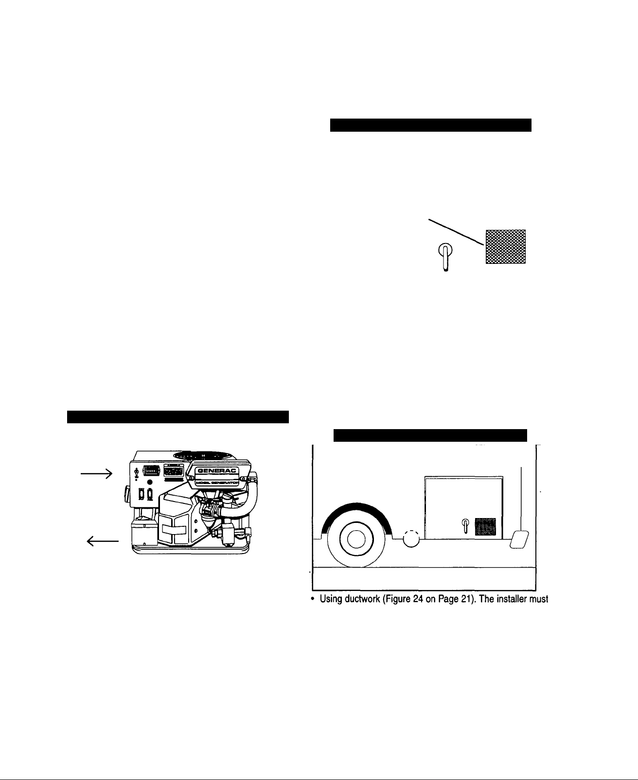
1. Generator Air Intake Screen
2. Engine Start/Stop Switch
3. Fuse
4. Circuit Breaker
5. Fuel Primer Switch
6. Generator AC Output Leads
7. 12 Volt Battery Connection (Partially hidden by 15)
8. Fuel Pump
9. Air Cleaner
10. Air Intake Tube
11. Carburetor
12. Oil Dipstick and Filler Tube
13. Data Decal
14. Hour Meter
15. Ignition Coil Assembly
— 1
Page 4

TABLE OF CONTENTS
OPERATING INSTRUCTIONS
GENERAL SAFETY RULES...............................inside cover
IDENTIFICATION RECORD
GENERATOR FEATURES
................................................
..................................................
READ THIS MANUAL THOROUGHLY
Operation and Maintenance.................................................................. 3
How to Obtain Service........................................................................... 3
Service Dealer Location......................................................................... 3
GENERATOR FAMIUARIZATION
Generator Applicability.......................................................................... 4
Safety....................................................................................................... 4
Generator AC Connection System....................................................... 4
OPERATING INSTRUCTIONS
Generator Control Panel........................................................................ 5
Automatic Choke.................................................................................... 5
Before Starting the Engine
Starting.................................................................................................... 6
Stopping the Generator......................................................................... 6
Applying Loads to Generator................................................................ 6
Attention Required After Submersion
Operation in High Grass or Brush
Operating Precautions
Effects of Moisture and Dirt.................................................................. 7
Don't Overload the Generator............................................................... 7
.................................................................
.................................................
.......................................................
........................................................................
5-6
6-7
ENGINE PROTECTIVE DEVICES
Automatic Low Oil Pressure Shutdown
High Temperature Shutdown................................................................ 7
Overspeed............................................................................................... 7
Low Voltage............................................................................................ 7
..............................................
INSTALLATION INSTRUCTIONS
INSTALLATION SAFETY RULES
......................................
14
1
GENERAL INSTALLATION INFORMATION
1
Purpose and Scope
Safety......................................................................................................15
Standards Booklet.................................................................................15
Equipment Description.........................................................................15
Engine Generator Operating Speed....................................................15
Generator AC Connection System......................................................15
.................................................
,............................15
LOCATION AND SUPPORT
Generator Location...............................................................................16
Generator Support
Suspended Mounting............................................................................16
Generator Restraint...............................................................................17
................................................................................
16
GENERATOR COMPARTMENTS
Compartments.......................................................................................17
Compartment Size.................................................................................18
Compartment Construcion
Sound Insulation Materials
6
6
Compartment Floor Cutouts................................................................19
Acoustics................................................................................................19
..................................................................
..................................................................
18
18
COOLING AND VENTILATION AIR
Generator Air Row.................................................................................20
Cooling Air Inlet Openings...................................................................20
Compensating for Restrictions...........................................................21
7
Testing the Installation.........................................................................21
GASOLINE FUEL SYSTEM
Fuel Tank................................................................................................22
Generator Fuel Supply Line............................................................22-23
SPECIFICATIONS
Fuel Requirements................................................................................. 8
Engine Oil Requirements
Generator Specifications....................................................................... 8
Engine Specifications............................................................................ 8
......................................................................
MAINTENANCE
Checking Engine Oil Level.................................................................... 9
Change Engine Oil
Change oil filter.................................................................................... 9
Engine Air Cleaner.............................................................................9-10
Clean Air Intake Screen........................................................................10
Spark Arrestor Muffler..........................................................................10
Engine Spark Plug................................................................................10
Fuel Filter...............................................................................................10
Cleaning the Generator........................................................................11
Battery....................................................................................................11
Service and Adjustments
Throttle Linkage Adjustment..........................................................11-12
Adjusting the Carburetor......................................................................12
Adjusting Valve Clearance...................................................................12
Major Service Manual...........................................................................13
Exercising the Generator.....................................................................13
Out of Service Protection.....................................................................13
Return the Unit to Service after Storage
Service Dealer Location
.................................................................................
....................................................................
............................................
.......................................................................
EXHAUST SYSTEM
Mufflers and Spark Arrestors
8
Type of Exhaust System.......................................................................23
Exhaust System Safety
..............................................................
.......................................................................
23
23
ELECTRICAL CONNECTIONS
Electrical Junction Box
Wiring......................................................................................................24
9
Generator AC Connections..................................................................24
Conduit...................................................................................................24
Isolating Different Power Sources......................................................25
Power Supply Cord...............................................................................25
Ground Fault Circuit Interrupters
BATTERY INSTALLATION
OPTIONAL ACCESSORIES
11
POST INSTALLATION TESTS...........................................29
INSTALLATION CHECK LIST............................................30
........................................................................
.......................................................
...........................................
26-27
...............................................
24
25
28
TROUBLESHOOTING........................................................31
MAJOR FEATURES AND DIMENSIONS...........................32
ELECTRICAL DATA...........................................................33
13
13
REPAIR PARTS.........................................................34 to 41
NOTES..........................................................................42 - 43
CALIFORNIA EMISSIONS WARRANTY
WARRANTY
..........................................................
.....................
back page
44 - 45
— 2 —
Page 5

READ THIS MANUAL THOROUGHLY
If you don't understand any portion of this manual,
contact Generac for a demonstration of actual start
ing, operating and servicing procedures.
Throughout this publication and on tags and decals
affixed to the generator, DANGER, WARNING, CAU
TION and NOTE blocks are used to alert you to spe
cial instruction about a particular operation that may
be hazardous if performed incorrectly or carelessly.
Observe them carefully.
These safety warnings cannot eliminate the hazards
that they indicate. Strict compliance with the special
instructions while performing the service plus "com
mon sense" are major measures to prevent acci
dents.
The following definitions apply to DANGER WARN
ING, CAUTION and NOTE blocks found throughout
the manual.
DANGER; Indicates an immediately hazardous sit
uation which, if not avoided, wiii resuit in death or
serious injury. Danger is iimited to the most
extreme situations.
WARNING: Indicates a potentially hazardous situa
tion which. If not avoid^, could result in death or
serious Injury.
CAUTION: Indicates a potentially hazardous situa
tion which, if not avoided, may result in minor or
moderate injury. Caution may also be used to alert
against unsafe practices.
NOTE: Indicates a statement of company policy as
the message relates directly or indirectly to the safety
of personnel or protection of property.
These symbols indicate the following:
Points out important safety information and, if
not followed, could endanger personal safety
and/or property of yourself and others.
Potential explosion hazard
Potential fire hazard
Potential electrical shock hazard
A
The operator (driver) is responsible for proper and
safe use of the vehicle, equipment on the vehicle, and
the safety of all vehicle occupants. We strongly rec
ommend that the operator read this Owner's Manual
and thoroughly understand all instructions before
using this equipment. We also strongly recommend
instructing other occupants in the vehicle to properly
start and operate the generator. This prepares them if
they need to operate the equipment in an emergency.
OPERATION AND MAINTENANCE
It is the operator's responsibility to perform all safety
checks; to make sure that all maintenance for safe
operation is performed promptly; and to have the
equipment checked by an Authorized Dealer periodi
cally. Normal maintenance service and replacement
of parts are the responsibility of the Owner/Operator
and, as such, are not considered defects in materials
or workmanship within the terms of the warranty.
Individual operating habits and usage contribute to
the need for maintenance service.
Proper maintenance and care of your industrial
mobile generator assures a minimum number of prob
lems and keeps your operating expenses at a mini
mum. See your authorized Dealer/Distributor for ser
vice aids and accessories.
HOW TO OBTAIN SERVICE
When your mobile generator set requires servicing or
repairs, simply contact an Authorized Service Facility
for assistance. Service technicians are factorytrained and are capable of handling all of your service
needs.
When contacting an Authorized Service Facility or the
factory about parts and service, always supply the
complete model number and serial number of your
unit as given on its data decal.
The warranty on your generator is included in this
Owner's Manual, as well as listings for repair parts.
SERVICE DEALER LOCATION
TO LOCATE THE NEAREST GENERAC SERVICING DEALER, PLEASE CALL OUR 800 NUMBER.
ONLY DEALER LOCATION INFORMATION CAN BE OBTAINED AT THIS NUMBER.
1-800-333-1322
3 —
Page 6

GENERATOR FAMILIARIZATION
GENERATOR APPLICABILITY
These generators have been designed and manufac
tured for supplying electrical power for recreational
vehicles. You should not modify the generator or use
it for any application other than for what it was
designed. If there are questions pertaining to its
application, write or call the factory. Do not use the
unit until you have been advised by a competent
authority.
DANGER: For fire safety, the generator must have
been properly installed in compliance with (1)
ANS1119.2-1975/NFPA 501C-1974 “Standard for
Recreational Vehicles”, Part III, “Installation of
Electrical Systems.” The generator also must have
been installed in strict compliance with the manu
facturer’s detailed installation instructions. After
installation, do nothing that might render the unit
in non-compliance with such codes, standards and
instructions.
You can use this generator to supply electrical power
for operating 120 volts, single phase, 60 Hertz, elec
trical loads. These loads can require up to 3600 watts
(3.6 kW) of power for the NP-36G series. The maxi
mum current at 120 volts is 30 amperes.
SAFETY
Before using the generator set, carefully read GEN
ERAL SAFETY RULES inside the cover. Comply with
these RULES to prevent accidents and damage to
equipment and/or property. Generac suggests copy
ing and posting the GENERAL SAFETY RULES in
potential hazard areas of the recreational vehicle.
Safety should be stressed to all operators of this
equipment.
GENERATOR AC
CONNEQION SYSTEM
These air-cooled NP Series generator sets power
120-volt, 30 amp AC loads for the NP-36G model.
The diagram below is a simple schematic (Figure 1)
of the generator’s AC connection system.
Figure 1 — Connection for 120 Volts Only
CAUTION: Do not overload the generator. Some
installations may require that electrical loads be
alternated to avoid overloading. Applying exces
sively high electrical loads may damage the gener
ator and may shorten its life. Add up the rated
watts of all electrical lighting, appliance, tool and
motor loads the generator will power at one time.
This total should not be greater than the wattage
capacity of the generator. If an electrical device
nameplate gives only volts and amps, multiply
volts times amps to obtain watts (volts x amps =
watts). Some electric motors require more watts of
power (or amps of current) for starting than for
continuous operation.
•4 —
Page 7

OPERATING INSTRUCTIONS
GENERATOR CONTROL PANEL
Mounted on the generator control panel (Figure 2) are
the following features:
Figure 2 — Typical Control Panel
FUEL PRIMER
Before starting a cold engine you must press this
switch to bring fuel from the tank to the carburetor.
This rocker type switch springs back into its original
position when you release it.
START/STOP SWITCH
To crank and start the engine, hold this switch at its
START position. Release the switch when the engine
starts. To stop an operating engine, press and hold
the switch in its STOP position until the engine shuts
off. The switch center position is the RUN position.
FUSE
Protects the engine DC control circuit against electrical
overload. If the fuse element has melted open due to
overloading, the engine cannot be cranked. If you must
replace it, use only an identical replacement fuse.
CIRCUIT BREAKER
Protects generator's AC output circuit against over
load, i.e., prevents unit from exceeding
wattage/amperage capacity.
HOUR METER
Indicates the time the engine-generator has operated,
in hours and tenths of hours. Use the hourmeter
along with the periodic maintenance schedule for your
generator set.
AUTOMATIC CHOKE
The engine is equipped with an autorriatic choke that
consists of two main components — choke solenoid
and prechoke.
CHOKE SOLENOID
During engine cranking (start/stop switch at START),
a solid state choke module signals the choke solenoid
to actuate and cycle (choke on/choke off) until engine
starts. The choke solenoid thus opens and closes the
carburetor choke valve only when the engine is crank
ing. When the engine starts, the choke cycling stops.
PRECHOKE
The choke system also has a temperature sensitive
metal strip that adjusts the choke valve angle accord
ing to ambient temperatures (i.e., in cold ambient
temperatures the choke valve closes more). Once
the engine starts, an element heats the temperaturesensitive strip to a normal operating condition, open
ing the choke valve. This may take about 3 minutes
in cooler weather.
BEFORE STARTING THE ENGINE
IMPORTANT: INSTRUCTIONS AND INFORMATION
IN THIS MANUAL ASSUME THE GENERATOR HAS
BEEN PROPERLY INSTALLED, CONNECTED,
SERVICED, TESTED AND ADJUSTED BY A QUALI
FIED INSTALLATION TECHNICIAN OF INSTALLA
TION CONTRACTOR.
INSTALLATION
Generator installation must have been properly com
pleted so it complies with all applicable codes, stan
dards and regulations and with the manufacturer's
recommendations.
ENGINE LUBRICATION
Have engine crankcase properly serviced with recom
mended oil before starting. Refer to "Maintenance"
and "Specifications" sections for oil servicing proce
dures and recommendations.
CAUTION: Any attempt to crank or start the engine
before you have properly serviced it with the rec
ommended oil may result in engine failure.
FUEL SUPPLY
The engine must have adequate supply of proper fuel
to operate. Before starting, check that sufficient fuel is
available.
NOTE: On some installations, the generator engine
may “share” the vehicle's gasoline fuel tank with the
vehicle engine. Some installations may provide sepa
rate fuel tanks for generator and vehicle engine.
■ COOLING AND VENTILATING AIR
Air inlet and outlet openings in the generator compart
ment must be open and unobstructed for continued
proper operation. Without sufficient cooling and venti
lating air flow, the engine-generator quickly overheats,
which causes it to automatically shutdown. Overheating
could also damage the unit or your vehicle.
Page 8

ENGINE EXHAUST GAS
Before starting the generator engine, you should be
sure there is no way for exhaust gases to enter the
vehicle interior and endangering people or animals.
Close windows, doors and other openings in the vehi
cle that, if open, might permit exhaust gases to enter
the vehicle.
DANGER: The generator engine gives off deadiy
carbon monoxide gas through! its exhaust system.
This dangerous gas, if breathed in sufficient con
centrations, can cause unconsciousness or even
death. Do not operate the generator if its exhaust
system is ieaking or has been damaged.
Symptoms of carbon monoxide poisoning are
(inability to think coherently, (b) vomiting, (c)
twitching muscles, (c) throbbing temples, (e) dizzi
ness, (f) headache, (g) weakness and sleepiness.
If you feel any of these symptoms, move into fresh
air immediately. If symptoms persist, get medical
help.
STARTING
IMPORTANT: Read the vehicle manufacturer’s
instructions. The owner/operator should become
familiar with the vehicle in which this generator is
installed. Differences exist between vehicles. For
example, some vehicles may use a transfer switch to
isolate dockside power from the generator, while
other vehicles may use an isolating receptacle. Some
vehicles may be equipped with a DC converter which
allows the generator to power certain DC lighting and
other DC loads.
To crank and start the generator engine, proceed as
follows;
1. Turn OFF electrical loads, using whatever means provid
ed in your vehicle (such as a main line circuit breaker or
transfer switch).
NOTE: If you start the engine with the start/stop
switch on the generator control panel, turn OFF loads
by setting the panei’s main breaker to its “OFF” or
“OPEN” position. Electrical load circuits will be turned
ON after the generator has started, stabilized and
warmed up.
NOTE: You only need to use the fuel primer during
the initial startup, after the unit has not been used for
an extended period of time or the fuel line has been
disconnected. The primer is used to prime the fuel
pump and carburetor.
2. To crank and start the engine, hold the start/stop switch
at START. Release the switch when the engine starts.
CAUTION: If the engine does not start after it has
been cranking for 15 seconds, release the start/stop
switch and try again. Holding the switch for ionger
than 15 seconds may damage the starter motor.
3. Let the engine run at no-load for a few minutes to stabi
lize and warm up the engine.
4. Turn ON electrical loads, using whatever means provided
(such as a main circuit breaker or transfer switch).
NOTE: If you start a warm generator engine, you
may press the start switch only slightly to engage the
ignition system. However, you should press and hold
the starter switch for a minimum of two (2) seconds to
energize the field boost system. If you start the
engine without energizing the field boost system, the
generator produces no AC output.
STOPPING THE GENERATOR
1. Turn OFF all electrical loads, using whatever means pro
vided (such as a main circuit breaker or transfer switch).
2. Let the generator run at no-load for a few minutes, to sta
bilize internal engine-generator temperatures.
3. Hold start/stop switch in its STOP position.
APPLYING LOADS TO GENERATOR
When applying electrical loads to the generator,
observe these guidelines:
• Before applying electrical loads, let the generator stabilize
and warm up for a minute or two.
• DO NOT overload the generator.
■ LEHING ENGINE STABILIZE
The generator supplies correctly rated frequency and
voltage only at the proper governed speed. Some
electrical appliances may be extremely sensitive to
voltage and frequency. Incorrect frequencies and/or
voltages can damage those appliances.
If electrical loads are applied at reduced operating
speeds, such loads imposed on the engine when suf
ficient power is not available may shorten engine life.
Never turn ON electrical loads until after the genera
tor engine has started and stabilized ON-speed.
_______________
AHENTION REQUIRED AFTER
SUBMERSION
If the motor home generator has been submerged in
water, it must NOT be started or operated. Following
any submersion in water, have an authorized Generac
Service Facility thoroughly clean and dry the generator.
OPERATION IN HIGH GRASS OR BRUSH
Never operate the generator while the vehicle is
parked in high grass, weeds, brush or leaves. Such
materials can ignite and burn from the heat of the
exhaust system. The generator exhaust system
becomes extremely hot during operation and remains
hot for a long time after it has shut down.
OPERATING PRECAUTIONS
Never operate the motor home generator set while
the vehicle is parked over dry leaves, dry grass or any
other combustible substance. The generator’s
exhaust system becomes extremely hot and can
cause a fire if it is too close to combustible materials.
— 6 —
Page 9

The generator’s exhaust system gives off DEADLY
carbon monoxide gas. This dangerous gas, if
breathed in sufficient concentrations, can cause
unconsciousness and even death. Never operate the
generator set with the vehicle inside any garage or
other enclosed area. Never operate the generator if it
has a leaky exhaust system. Close windows in the
vicinity of the generator exhaust outlet and take any
other steps to prevent exhaust gases from entering
rooms or areas occupied by people or animals.
EFFEQS OF MOISTURE AND DIRT
Keep the generator set as clean and dry as possible.
Protect unit against excessive dust, dirt, corrosive
vapors, road splash, etc. Permitting dirt and moisture
to accumulate on oenerator windings will have an
adverse effect on the insulation resistance of those
windings.
When moisture is allowed to remain in contact with
windings, some of the moisture will be retained in
voids and cracks in the insulation. This causes a
reduced insulation resistance and will eventually
cause problems. Dirt will make the problem worse,
since dirt tends to hold moisture in contact with wind
ings. Salt (as from sea air) will also worsen the prob
lem since it tends to absorb moisture from the air. Salt
and moisture, when combined, form a good electrical
conductor.
DO NOT OVERLOAD
THE GENERATOR
You can read the rated wattage/amperage capacity of
your penerator on the generator data decal (see
‘^Identification Record” on Page 1).
Applying electrical loads in excess of the unit’s rated
capacity will cause the engine-generator to automati
cally shutdown.
To avoid overloading, add up the wattage of all con
nected electrical lighting, appliance, tool and motor
loads. This total should not be greater than the gener
ator’s rated wattage capacity.
• Most lighting, appliance, tool and motor loads indicate
their required watts on their nameplate or data plate. For
light bulbs, simply note the wattage rating of the bulb.
• If a load does not show its rated wattage, multiply that
load’s rated VOLTS times AMPS to obtain WATTS.
• Induction type motors (such as those that run the vehicle’s
furnace fan, refrigerator, air conditioner, etc.) need about 2-
1/2 times more watts of power for starting than for running
(for a few seconds during motor starting). Be sure to allow
for this when connecting electrical loads to the generator.
First, figure the watts needed to start electric motors in the
system. To that figure, add the running wattages of other
items that will be operated by the generator.
• On a new generator do not apply heavy electrical loads
for the first two or three hours of operation.
This generator has a computer that monitors low oil pres
sure, oil temperature, engine speed, and low voltage out
put. This section discusses those protective devices.
AUTOMATIC LOW OIL PRESSURE SHUTDOWN
The engine is equipped with an oil pressure sensor
that shuts down the engine automatically when oil
pressure is too low. If the engine shuts down by itself
and the fuel tank has enough gasoline, check the
engine oil level.
■ INITIAL STARTUP______________________
During initial startup, a time delay built into the shut
down control system allows oil pressure to build. The
delay allows the engine to run for about 10 seconds
before sensing oil pressure.
■ SENSING LOW PRESSURE
If the system senses low oil pressure during opera
tion, the engine shuts down. If you do restart the
engine after a low oil pressure shutdown and have
not corrected the low oil level, the engine runs for
about 10 seconds as described above then stops.
______________
HIGH TEMPERATURE SHUTDOWN
A temperature switch with normally-open (N.O.) con
tacts is mounted near the oil filter. If engine tempera
ture were to exceed a preset temperature, the switch
contacts close and the engine shuts down.
ENGINE PROTECTIVE DEVICES
OVERSPEED
If engine speed is increased manually (or othenwise)
beyond the control of the computer control system,
the computer disables the load capability of the gen
erator and shuts down the engine.
WARNING: Do not attempt to physically adjust or
control the engine speed. Equipment damage or
personal injury may result.
LOW VOLTAGE
The computer monitors the voltage output of the gener
ator. If voltage sensors indicate that voltage has
dropped below a preset level, the engine will automati
cally shut down. Once the unit has shutdown, the com
puter is automatically reset when you restart the engine.
NOTE: The computer allows for the low voltage out
put that occurs during startup. A time delay that
allows the engine to start and warm up is pro
grammed into monitoring the system.
CAUTION: Before restarting a generator that has
been shutdown, disconnect all loads the generator
might power by whatever means provided, such as
the recreational vehicle’s main circuit breaker.
— 7 —
Page 10

SPECIFICATIONS
FUEL REQUIREMENTS
These generators are equipped with gasoline fuel
systems as standard equipment. Specific installa
tions may provide either a separate fuel tank for the
generator, or the generator may “share” the vehicle
engine’s fuel tank.
NOTE: Installations using a “shared" fuel tank may
have a generator fuel pickup tube that is shorter than
the vehicle engine’s pickup tube. Such an arrange
ment causes the generator engine to “run out of gas”
while adequate fuel for the vehicle remains in the
tank.
To reduce lead and carbon deposits use high quality
UNLEADED gasoline with the generator. Leaded
REGULAR grade gasoline is an acceptable substi
tute.
NOTE: Using “Unleaded” gasoline contributes to
longer engine valve life by reducing lead and carbon
deposits.
CAUTION: Generac does not recommend using
any gasoline containing alcohol, it must not con
tain more than 10 percent ethanol and it must be
removed from the generator during storage. Do
NOT use any gasoline containing methanol. If you
use gasoline with alcohol, inspect more frequently
for fuel leaks and other abnormalities.
FUEL CONSUMPTION (IN GALLONS PER HOUR):
LOAD GASOLINE
NO 0.13
HALF
FULL
0.20
0.40
ENGINE OIL REQUIREMENTS
The recommended oils include the following;
• During summer months: SAE 30. An acceptable substi
tute is SAE 10W-30.
• During winter months: SAE 5W30. DO NOT USE SAE
10W-40.
Crankcase and oil filter capacity is about 950ml or
one (1) quart. Use no special additives. See
“Maintenance” section for oil level check and fill pro
cedures.
GENERATOR SPECIFICATIONS
Model..............................................................Impact-36G
Rated Maximum Continuous
AC Power Output
Rated Voltage............................................120 volts AC
Rated Maximum Continuous
Current at 120 volts
Phase
...........................................................
Rated AC Frequency................................................60 Hz.
Maximum Battery
Recommended Battery
Cranking Current
..............................
..................................
..............................................
3600 watts (3.6 kW)
30 AC amperes
Single Phase
400 amps
ENGINE SPECIFICATIONS
Type of Engine
Cooling Method..................................................Air-cooled
Displacement............................................................220cc
Type of Governor
Air Cleaner
Starter..................................................12 volt DC electric
Ignition System
Recommended Spark Plugs
Spark Plug Gap...................................0.030 inch (0.8mm)
......................................................
...............................................
.................................................
.................................................
.............
Champion RC12YC
GN-220
Electronic
Paper element
Solid state
8 —
Page 11

MAINTENANCE
This section includes information about simple main
tenance which includes the following tasks;
• Checking engine oil level.
• Changing engine oil.
• Changing oil filter.
• Changing the air cleaner.
• Cleaning the air intake screen.
• Cleaning spark plug.
CHECKING ENGINE OIL LEVEL
Check engine crankcase oil level at least every eight
hours of operation, or before each use (Figure 3).
• Be sure the generator is as level as possible.
• Remove oil dipstick and wipe dry with clean, lint-free
cloth.
• Install and tighten oil dipstick, then remove again.
• Oil should be at dipstick FULL mark. If necessary, add
the recommended oil to the FULL mark only. DO NOT
FILL ABOVE “FULL” MARK.
• Install and tighten oil dipstick cap before operating the
engine.
Figure 3 — Oil Dipstick and Fill Tube
<f=.
* Install and tighten dipstick cap before operating engine.
CHANGE OIL FILTER
Replace the engine oil filter after the first 8 hours of
operation, every 50 operating hours thereafter.
• Turn oil filter counterclockwise to remove (Figure 4).
Figure 4 — Oil Drain Plug and Engine Oil Filter
• Turn new filter clockwise until its gasket contacts lightly
with the filter adapter. Then tighten with an additional 3/4
to one turn by hand.
• Run engine and check for leaks.
NOTE: Check oil level and fill to full mark after
checking for leaks. Filter will retain some oil.
NOTE: See “Engine Oil Requirements” on Page 8 for
recommended oils.
CHANGE ENGINE OIL
Change engine oil after the first 8 hours of operation.
Thereafter, change oil every 50 operating hours.
Change oii more frequentiy if operating consistently
under heavy load or at high ambient temperatures.
• Warm up engine for at least five minutes, then shut down.
• With engine still warm from running, clean area around
oil drain plug and remove oil drain plug (Figure 4). Drain
oil completely into a suitable container.
• When oil has drained, install and tighten drain plug.
• Remove oil dipstick and fill crankcase with the recom
mended oil (See Page 8). The engine crankcase can hold
about 1 quart (950ml). DO NOT FILL ABOVE “FULL”
MARK.
ENGINE AIR CLEANER
Paper Filter: Once every 25 operating hours or once
each year (whichever comes first), clean or replace
the paper filter (Figure 5).
10;
Figure 5 — Engine Air Cleaner Assembly
Follow the steps on page
PAPER
FILTER
— 9 —
Page 12

• Remove air cleaner cover, then remove paper filter.
• Clean air filter by gently tapping it on a solid surface. If
the filter is too dirty, replace it with a new one. Dispose of
the old filter properly.
• Clean air cleaner cover then insert new paper filter into
cover and assemble to the base of the air cleaner.
CLEAN AIR INTAKE SCREEN
Clean all foreign material from the air intake screen
(Figure 6) at lease once every 100 hours of operation.
Clean more often if necessary.
Inspect the area around the generator exhaust muffler
periodically and remove all grass, leaves, dirt, etc.
from this area.
Figure 6 — Clean Air Intake Screen
ENGINE SPARK PLUG
Clean engine spark plug and set gap to 0.030 inch
^.76mm) every 100 hours of operation (Figure 7).
Clean by scraping or wire brushing and washing with
commercial solvent. DO NOT BLAST CLEAN SPARK
PLUG.
Figure 7 — Setting Gap on Spark Plug
CAUTION; Sparking can occur if wire terminal
does not fit firmly over spark plug terminal end. If
necessary, reform wire terminal to obtain a tight fit.
FUEL FILTER
Remove and replace fuel filter (Figure 8) every 100
hours of operation or once each year, whichever
occurs first.
Figure 8 — Fuel Filter
10 —
Page 13

CLEANING THE GENERATOR
Keep your generator set as clean and dry as possible.
Dirt and moisture that are permitted to accumulate on
electrical windings have an adverse affect on the
insulation resistance of those windings.
Moisture that is allowed to remain in contact with wind
ings will be retained in voids and cracks of the wind
ings. Dirt makes the problem worse, since it tends to
hold the moisture into contact with the windings. Salt,
as from sea air, worsens the problem since it tends to
absorb moisture from the air. The combination of salt
and moisture makes a good electrical conductor.
CAUTION! Do NOT use a forceful spray of water to
clean the generator. Water will enter the generator
interior and cause probiems, and may also conta
minate the generator fuel system.
BAHERY
All lead-acid storage batteries will discharge when not
in use. Inspect the generator battery as follows:
■ ONCE WEEKLY
Inspect battery posts and cables for tightness, corro
sion. Clean and/or tighten as necessary.
Also check battery fluid level, and, if necessary, fill
with DISTILLED WATER ONLY. DO NOT USE TAP
WATER IN BATTERY.
■ EVERY SIX MONTHS
Have the battery state of charoe and condition
checked by an automotive service facility. This should
be done with an automotive type battery hydrometer.
DANGER; Storage batteries give off explosive
hydrogen gas. This gas can form an explosive
mixture around the battery for several hours after
charging. The siightest spark can ignite the gas
and cause an explosion. Such an expiosion can
shatter the battery and cause biindness or other
injury. Any area that houses a storage battery
must be properly ventilated. Do not allow smok
ing, open flame, sparks or any spark producing
tools or equipment near the battery.
_______________________
___________________
SERVICE AND ADJUSTMENTS
■ ENGINE SPEED_________________________
Engine speed is completely computer-controlled.
There is no adjustment for speed on the unit. The
computer adjusts the engine speed using an electron
ic governor throttle control. The computer monitors
the demand for power and adjusts the engine speed
accordingly. This allows the engine to produce only
the power required, resulting in fuel economy as well
as lowering the overall noise emitted.
NOTE: The computer will disable the electrical load
capabilities of the generator and enter a fault condi
tion if you accelerate the throttle manually or any
other way.
THROHLE LINKAGE ADJUSTMENT
If needed, you can adjust the length of the linkage rod
between the electronic governor lever arm and the
carburetor throttle lever arm. This adjustment helps to
establish the proper travel relationship between the
two lever arms. It this adjustment is not properly set,
the computer will NOT have control of the full range of
engine speed. If the rod adjustment is set too snort,
the computer will not have access to wide open throt
tle or “full power" conditions. If the rod adjustment is
set too long, the computer will not have access to
closed throttle or “no power” conditions.
Use the following procedure to assure the linkage rod
is properly adjusted;
1. Start the generator, then shut it down right away. As the
engine coasts to a stop, observe from above the engine
as the throttle lever on the carburetor rotates counter
clockwise.
2. There should be a gap of 0.003 inch (0.08-0.5mm)
between stop tab on throttle lever arm and the stop block
on the carburetor die casting (Figure 9).
Figure 9 — Gap Between Stop Tab
and Stop Block
DANGER; Battery electrolyte fluid is an extremely
caustic sulfuric acid solution that can cause
severe burns. Do not permit fiuid to contact eyes,
skin, clothing, painted surfaces, etc. Wear protec
tive goggies, protective clothing and gloves when
handling a battery. If you spill the fluid, fiush the
affected area immediately with clear water.
DANGER; Do not use any jumper cables or boost
er battery to crank and start the generator engine.
If any battery has discharged, remove it from the
vehicle for recharging.
—11 —
Page 14

3. With pliers, lightly compress the spring clip on the carbu
retor lever arm. This allows the linkage rod to slide freely
through the clip. While the clip is compressed, rotate the
throttle lever in the appropriate direction to increase or
decrease the gap until there is 0.003 inch (0.08-0.5mm)
clearance (Figure 10).
Figure 10 — Adjusting Throttle Linkage
1. Loosen the rocker arm jam nut. Use an alien wrench to
turn the pivot ball stud while checking clearance between
the rocker arm and the valve stem with a feeler gauge
(Figure 11).
Figure 11 — Adjusting Valve Clearance
2. When valve clearance is correct, hold the pivot ball stud
with the alien wrench and tighten the rocker arm jam nut
with a crows foot. Tighten the jam nut to 65-85 inchpounds torque. After tightening the jam nut, recheck valve
clearance to make sure it did not change (Figure 12).
4. Release spring clip so you can secure adjustment. This
allows the carburetor and the electronic governor to be
synchronized.
ADJUSTING THE CARBURETOR
The carburetor of your generator is preset at the fac
tory. The carburetor should not be tampered with, as
this will void the emission control system warranty. If
your generator is used at altitudes in excess of 5,000
feet, consult your Generac Authorized Service Facility
regarding high altitude jetting changes.
ADJUSTING VALVE CLEARANCE
After the first 50 hours of operation, you should adjust
the valve clearance in the engine.
When adjusting valve clearance, the engine should
be at room temperature and the piston should be at
Top Dead Center (TDC) of its compression stroke
(both valves closed). Correct clearance is 0.001-
0.003 inch (0.03-0.07mm). Adjust valve clearance as
follows:
Figure 12 — Tightening Jam Nut
Tighten Jam Nut to
65-85 inch-pounds
(7-10 N-m)
— 12 —
Page 15

MAJOR SERVICE MANUAL
To obtain a service manual for your generator, order it
from your dealer/distributor or contact the factory. Be
sure to identify your unit’s MODEL NUMBER and
SERIAL NUMBER.
EXERCISING THE GENERATOR
Generac recommends that you start and operate the
generator at least once every seven days. Let the unit
run for at least 30 minutes to “exercise” the engine.
OUT OF SERVICE PROTEQION
If you cannot exercise the generator every seven
days and it is to be out of service longer than 30 days,
prepare the generator for storage as follows:
• Start the engine and let it warm up.
• While the engine is still warm from running, drain the oil
completely. Refill crankcase with recommended oil. See
“Specifications.”
• Attach a tag to the engine indicating the viscosity and
classification of the oil in the crankcase.
• Remove spark plug and add about 1/2 ounce (15ml) of
clean, fresh engine oil into spark plug threaded openings.
Crank engine several times to distribute oil, then install
and tighten spark plug.
• Remove the battery and store in a cool, dry room on a
wooden board. Never store the battery on any concrete
or earthen floor.
• Clean and wipe the entire generator.
RETURN UNIT TO SERVICE
AFTER STORAGE
To return the unit to service after storage, proceed as
follows:
• Check tag on engine for oil viscosity and classification.
Verify that the correct recommended oil is used in engine.
If necessary, drain and refill with proper oil.
• Check battery. Fill all cells to the proper level with distilled
water. DO NOT USE TAP WATER IN THE BATTERY.
Recharge battery to 100% state of charge, or, it defective,
replace the battery.
• Turn OFF all electrical loads, then start the engine.
• Let engine warm up.
• Apply electrical loads to at least 50% of the unit’s rated
wattage capacity.
• When engine is thoroughly warmed up, shut it down.
THE GENERATOR IS NOW READY FOR SERVICE.
SERVICE DEALER LOCATION
TO LOCATE THE NEAREST GENERAC SERVICING DEALER, PLEASE CALL OUR 800 NUMBER.
ONLY DEALER LOCATION INFORMATION CAN BE OBTAINED AT THIS NUMBER.
1-800-333-1322
— 13-
Page 16

INSTALLATION SAFETY RULES
DANGER: FOR FIRE SAFETY, INSTALLATION OF A GENERATOR INTO A RECREATIONAL
VEHICLE MUST COMPLY STRICTLY WITH ARTICLE 551, NFPA 70; ANSI C1-1975; AND,
ANSI All9.2-1975/NFPA 501C “STANDARD FOR RECREATIONAL VEHICLES" (PART 3,
“INSTALLATION OF ELECTRICAL SYSTEMS"). IN ADDITION, THE MANUFACTURER'S
INSTRUCTIONS AND RECOMMENDATIONS MUST BE COMPLIED WITH.
NOTICE TO INSTALLER
The Installation Instructions have been published by
Generac Corporation to aid in the installation of the
products described in this manual. Generac assumes
that installation personnel are familiar with the proce
dures for installing such products, or similar products
that Generac manufactures. Generac also assumes
that personnel have been trained in the recommended
installation procedures for these products and that
such training includes (a) use of common hand tools,
(b) use of special Generac tools, and (c) use of any
tools and/or equipment from other suppliers.
We could not possibly know of and advise the recre
ational vehicle trade of all conceivable methods, proce
dures or techniques by which to perform an installa
tion. We could not know of the possible hazards that
might result from each installation method, procedure
or technique. We have not undertaken any such wide
evaluation. Therefore, people who use a method, pro
cedure or technique that Generac does not specifically
recommend must first completely satisfy themselves
that their safety, the safety of the vehicle's occupants
and the products's safety is not endangered by the
method, procedure or technique selected.
Information, illustrations, specifications, etc., contained
in this Installation Manual are based on the latest infor
mation available at the time of publication. Every effort
has been expended to be sure that such data is both
accurate and current. However, the manufacturer
reserves the right to change, alter or otherwise
improve this product at any time without prior notice.
SAFETY RULES
A Gasoline is extremely FLAMMABLE and its vapors
are EXPLOSIVE. Do not permit smoking, open
flame, sparks or any source of heat in the vicinity
while handling gasoline. Comply with all laws gov
erning the storage and handling of gasoline.
A Fuel lines must be propedy installed, properly fas-
tened and free of leaks. There must be no possi
bility of gasoline vapors entering vehicle interior.
• You are required to install an approved, flexible,
non-conductive fuel line between the generator
fuel connection point and rigid fuel lines.
A If the generator can be equipped with a liquid
^ propane (LP) gas fuel system, install the unit so it
complies with all codes, standards and regulations
pertaining to such systems. LP gas is highly explo
sive. The gas tends to settle in low areas where
even the slightest spark can ignite it and cause an
explosion. Do not allow gas vapors to enter the
vehicle.
• Engine exhaust gases contain DEADLY carbon
monoxide gas. This dangerous gas, if breathed in
sufficient concentrations, can cause unconscious
ness or even death. Install the exhaust system in
strict compliance with applicable codes, standards
and regulations. There must be no possibility for
exhaust gases entering the vehicle interior and
endangering people or animals.
A The generator set produces dangerously high
electrical voltage. Contact with bare wires, bare
terminals, etc., will result in extremely hazardous
and possibly lethal electrical shock.
• All applicable electrical codes, standards and reg
ulations must be strictly complied with in the instal
lation and use of this equipment.
• The generator must be properly grounded (bond
ed) to the vehicle chassis or frame.
A If the vehicle electrical circuits can be powered by
^ any other source of electricity (such as a “dockside-
power receptacle), there must be no possibility of
connecting the different power sources to the vehi
cle circuits at the same time. The “dockside” (utility)
power source must be positively isolated from the
vehicle circuits whenever the generator is operat
ing. Failure to isolate the vehicle circuits from the
dockside power supply when the generator is run
ning may result in damage to the generator or seri
ous injuiy or death to dockside (utility) power work
ers due to backfeed of electrical energy.
• Never work on the equipment while standing in
water, while barefoot, or while hands or feet are
wet. Dangerous electrical shock will result.
• Jewelry conducts electricity, which can cause dan
gerous electrical shock. Remove all jewelry (such
as rings, watches, or bracelets) before working on
this equipment.
A The generator requires an adequate flow of air for
cooling and ventilation. Without sufficient cooling
air flow, the engine-generator quickly overheats,
which causes serious damage to the generator, a
fire or an explosion. Generator air inlet and outlet
openings must be provided in strict compliance
with the manufacturer's recommendations.
• Never work on this equipment while physically pr
mentally fatigued. Stay alert at all times.
A Storage batteries give off EXPLOSIVE hydrogen
^ gas while charging. The battery used for cranking
and starting this generator should be installed in
its own vented compartment. Provide adequate
ventilation for the battery, to prevent explosive
hydrogen gas from accumulating.
A Never insert any tool or other object through open-
^ ings in the generator interior, even if the unit is not
running. You might seriously injure yourself or
damage the equipment.
• Staying alert and using “common sense” are major
measures for preventing accidents.
— 14 —
Page 17

GENERAL INSTALLATION INFORMATION
PURPOSE AND SCOPE OF MANUAL
These Installation Instructions have been prepared
especially for the purpose of familiarizing installers and
owners of the applicable equipment with the product's
installation requirements. Give serious consideration to
all information and instructions in the Manual, both for
safety and for continued reliable operation of the
equipment.
Because of the different recreational vehicle models
and the variations between the models, it would be
extremely difficult, if not impractical, to provide detailed
instructions on every installation possibility. For that
reason, instructions and illustrations in this manual are
general in nature. Illustrations are not intended to
serve as detailed installation blueprints.
The installation should comply strictly with all applica
ble codes, standards and regulations pertaining to the
installation and use of this product. If any portion of
this manual appears to be in conflict with such codes,
standards or regulations, the applicable codes, stan
dards or regulations must take precedence over the
manual.
SAFETY
Before handling, installing, operating or servicing this
equipment, be sure to read carefully the “Notice to
Installer” and “Safety Rules” at front of this manual.
Comply with all SAFETY RULES to prevent death, per
sonal injury or damage to equipment and/or property.
Stress safety to all installers, operators and service
technicians who work on this equipment.
5. California Administrative Code, Title 25, available from the
State of California, Documents Section, P.O. Box 1015,
North Highlands, CA 95660.
6. CSA Electrical Bulletin 946, available from the Canadian
Standards Association, Housing and Constructions
Materials Section, 178 Rexdale Boulevard, Rexdale,
Ontario, Canada, M9W1R3.
EQUIPMENT DESCRIPTION
Instructions and information in this section pertain to
Generac Impact air-cooled generators — more specifi-"
cally, the installatiori of Impact 36G recreational vehi
cle generators. These generators are designed specifi
cally for installing in recreational vehicles.
ENGINE GENERATOR
OPERATING SPEED
The generators are driven by gasoline-powered, sin
gle-cylinder engines. The engines drive revolving fields
(rotors), high frequency, permanent magnet alterna
tors. The generators supply 120 volts AC at 60 Hertz.
The generators revolving fields are driven at a variable
speed depending on the demand for power.
Computers monitor that demand and adjust the engine
speed to provide adequate power to the connected
loads.
STANDARDS BOOKLETS
Installation, use and servicing of this equipment should
comply strictly with published standards, as well as the
manufacturer's recommendations. The following stan
dards booklets (latest revision) are available from the
sources indicated:
1. NFPA Standard 501C, “Standard for Recreational
Vehicles”, available from the National Fire Protection
Association, Batterymarch Park, Quincy, MA 02269.
2. NFPA 70, “NFPA Handbook of the National Electric Code”,
obtained from same address as Item 1.
3. ANSI Cl-1975 and ANSI 119.2-1975, available from the
American National Standards Institute, 1430 Broadway,
New York, NY 10018.
4. ANSI A119.2/NFPA 501C, available from the Recreational
Vehicle Association, 1896 Preston White Drive, Reston, VA
22090.
GENERATOR AC
CONNECTION SYSTEM
The generators are equipped with single voltage AC
connection systems. The following facts pertain to
such a connection system:
• On the Impact units, the 120 volts, connections system is
protected by a circuit breaker.
• The AC connection system on all air-cooled Impact gener
ators uses a GROUNDED neutral.
• A separate green ground wire is connected to the recre
ational vehicle's junction box.
15 —
Page 18
LOCATION AND SUPPORT
GENERATOR LOCATION
The most desirable location for the generator set is
between the vehicle's main frame members However,
this is seldom possible. Most units must be installed on
the side of the vehicle and are difficult to reinforce.
Many recreational vehicles have been factory
equipped with an area for the generator set. Some
vehicles may even have a generator compartment,
provided by the vehicle manufacturer.
Plan the generator location based on the following:
• The generator set must be installed on a framework that is
part of the recreational vehicle, as outlined in the para
graph entitled “Generator Support."
• The location must provide an access opening that is large
enough to permit generator removal (unless the generator is
to be removed from underneath the supporting framework.
• The location must provide easy access to frequently ser
viced components, such as filters, oil drains, spark plugs
and other common maintenance parts.
• The location must provide sufficient room to allow mini
mum clearance of at least 1 inch between all sides and 11/2 inches on top of the generator. If sound insulation is to
be used on compartment walls and ceiling, the minimum
recommended applies to the space between the generator
and such insulation.
• The location must provide adequate cooling and ventilating
air flow for the generator without a great deal of work and
expense.
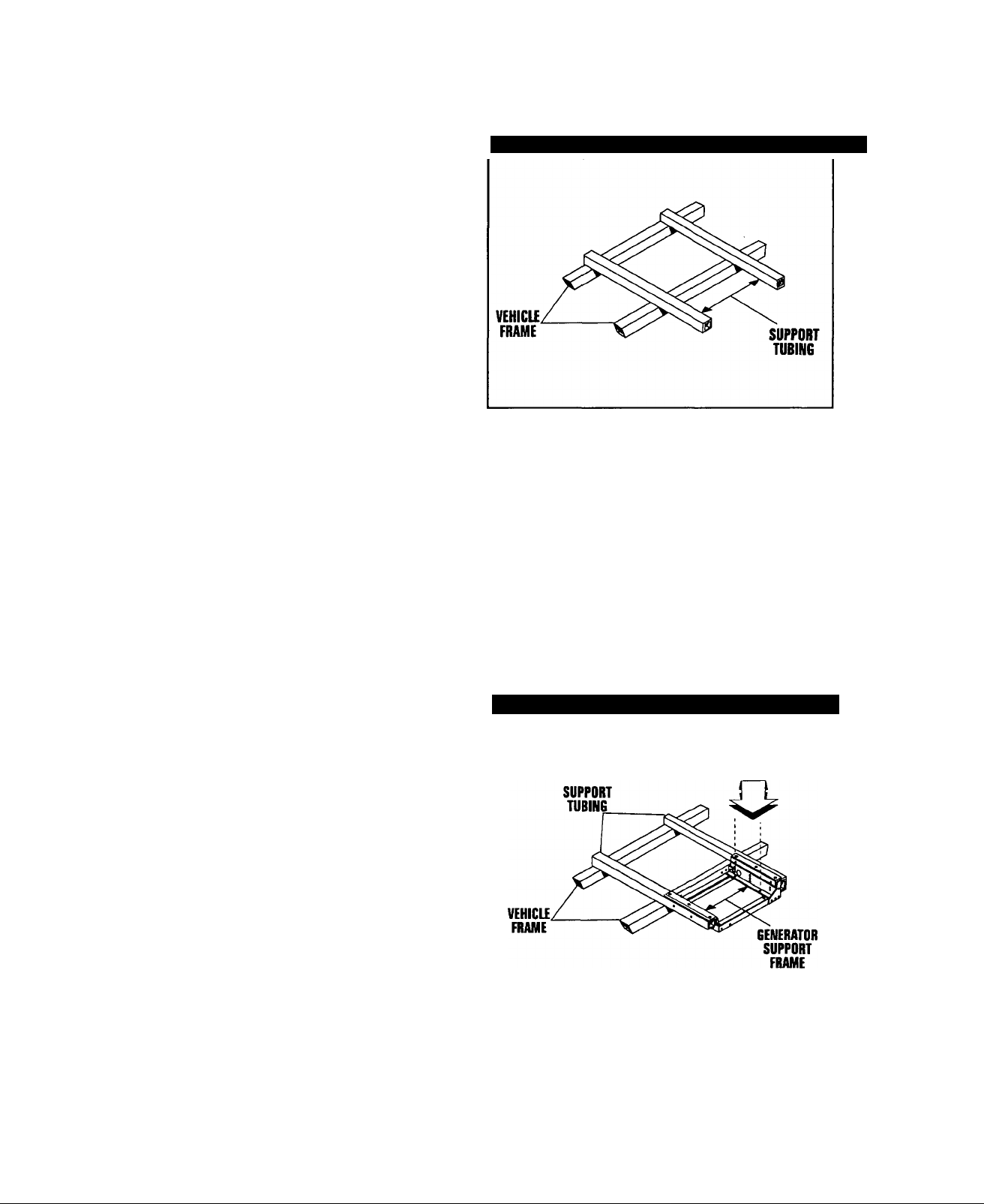
GENERATOR SUPPORT
The generator must be securely attached to a metal
framework that has been made part of the vehicle
frame structure by bolting or welding. The metal frame
work on which the generator will rest and which will
restrain the generator set should consist of at least two
horizontal beams. These beams should consist of (a)
1-1/2 inch square, 11 gauge steel tubing OR (b) 1-1/2
inch, 11 gauge angle iron. A typical supporting frame
with horizontal support tubing, is shown in Figure 13.
The generator can be installed so that it sits on top of
the horizontal support tubing, if the vehicle design per
mits. Another method is to suspend the generator
below the horizontal support tubing by means of suit
able, structurally sound metal framework. The following
general rules apply:
• Vehicle construction MUST be capable of supporting the
weight of the generator.
• Whether the generator is mounted above the horizontal
support tubing or suspended below the tubing, the sup
porting frame used must be structurally sound.
• If the generator cannot be bolted directly to the supporting
frame or support tubing, consider using additional tubing,
angle brackets or other supports to give the supporting
frame sufficient strength.
Figiire 13 — Typical Horizontal Support Frame
SUSPENDED MOUNTING
If you are going to suspend the generator below the
horizontal support tubing, the suspension method you
use with the vehicle frame members must have the fol
lowing: (a) be able to support the weight of the genera
tor; and (b) provide sufficient restraint for the genera
tor. One typical suspended mounting system is shown
in Figure 14. The location of a suspended mounting
system must be carefully planned, keeping the follow
ing general rules in mind:
• Protect the generator against road splash and debris.
Baffles or splash guards may be required to protect certain
areas of the generator. To make sure the generator is ade
quately protected, road test the installation through mud,
water and slush.
Figure 14 —Typical Suspended Mounting System
GENERATOR MOUNTING
HOLES F0R3/8°-16
BOLTS (BOTH SIDES)
The installer must make certain that selected location will
permit adequate cooling and ventilating air flow to be sup
plied.
—16 —
Page 19
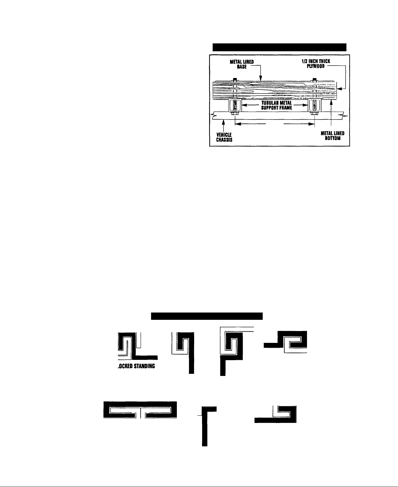
GENERATOR RESTRAINT
Use four 3/8“-16 hardened steel bolts (Grade 5) to fas
ten the generator to the supporting frame or the sup
port tubing. These bolts must pass through (a) the
generator mounting base, (b) the compartment floor, if
a compartment is used, and (c) the supporting frame
work (Figure 15). All bolts must be long enough so that
when tight, at least 3 threads are visible past the
retaining lock nuts. Refer to “COMPARTMENT’ section
for location of generator mounting holes.
Figure 15,— Typical Generator Restraint
GENERATOR COMPARTMENTS
COMPARTMENTS
The generator set may or may not be installed inside a
compartment that is constructed specifically for hous
ing a generator. This section applies to generator com
partments when they are installed. The following gen
eral rules apply to compartments:
• The generator compartment should be either con
structed of, or lined with, 26 gauge galvanized
steel.
IMPORTANT: ALUMINUM IS NOT AN ACCEPTABLE
ALTERNATIVE TO GALVANIZED STEEL, DUE TO
ALUMINUM'S LOW MELTING POINT.
• If the compartment is lined with galvanized steel, it
may be constructed of any material. Generac rec
ommends that the compartment be constructed of
1/2-inch thick plywood, with the floor made of a
double thickness of plywood for added strength.
• All seams, splices and joints of the compartment
walls (unless vapor tight by design) should be
caulked.
Figure 16 — Types of Lock Senms
IMPORTANT: CAULKING MUST BE DONE SO THAT
THE CAULKING MATERIAL WILL STAY IN PLACE
PERMANENTLY. PRESSING SUCH MATERIALS AS
PUTTY TAPE ONTO JOINTS AND SEAMS WILL NOT
MEET THAT REQUIREMENT. A HIGH QUALITY SILI
CONE RUBBER SEALANT IS RECOMMENDED.
• Holes and openings through the compartment
walls for passage of electrical conduit, conductors,
etc, into vehicle living area must be sealed vaportight with silicone ruboer base sealant.
• If you use flexible metal conduit, seal the conduit
at the end where it terminates inside the junction
box. Flexible metal conduit is NOT vapor tight
along its entire length.
• Seams and joints of the galvanized steel (whether
used as a liner or the compartment itself) must be
lapped and mechanically secured. Such seams
may be manufactured, welded, bolted, riveted, or
screwed. Manufactured lock seams are shown in
Figure 16.
FOU)
ACME LOCK
OFFSET
DOUBLE LOCK DOUBLE SEAM
GORDON SEAM LOCK SEAM
STANDARD LAP JOINT
— 17 —
Page 20
COMPARTMENT SIZE
Plan the compartment size carefully. Provide a mini
mum of at least 1 inch (2” recommended) of clearance
between the generator and compartment walls and 1 inch
(2’ recommended) of clearance between the generator
and the ceiling AFTER you have lined the compart
ment with metal, and AFTER you have installed sound
insulation (Figure 17).
NOTE: Refer to the "Major Features and Dimensions”
drawing in the back of this manual.
Figure 17 — Provide Clearance Around Generator
PLYWOOD
COMPARTMENT
11NCH MINIMUM CLEARANCE
ON ALL SIDES (2" RECOMMENDED)
• Line the entire compartment interior with 26 gauge galva
nized steel as described above.
• Line the exterior (underside) of the compartment floor with
26 gauge galvanized steel.
• Vapor seal all compartment seams and joints, to prevent
poisonous, flammable or explosive vapors from entering
the vehicle interior. Refer to the sealant information as
noted previously.
NOTE: Silicone rubber base sealant is an acceptable
caulking material. Pressing putty tape onto compart
ment joints and seams is NOT acceptable.
• After the compartment has been metal lined and vapor
sealed, line the compartment interior walls and ceiling with
an approved, non-flammable sound insulating material.
See “Sound Insulating Materials.”
1 INCH
MINIMUM
TOP VIEW OF
GENERATOR
LT
CLEARANCE
ABOVE
GENERATOR
(2" RECOMMEND
ED)
METAL UNING-
INSULATION
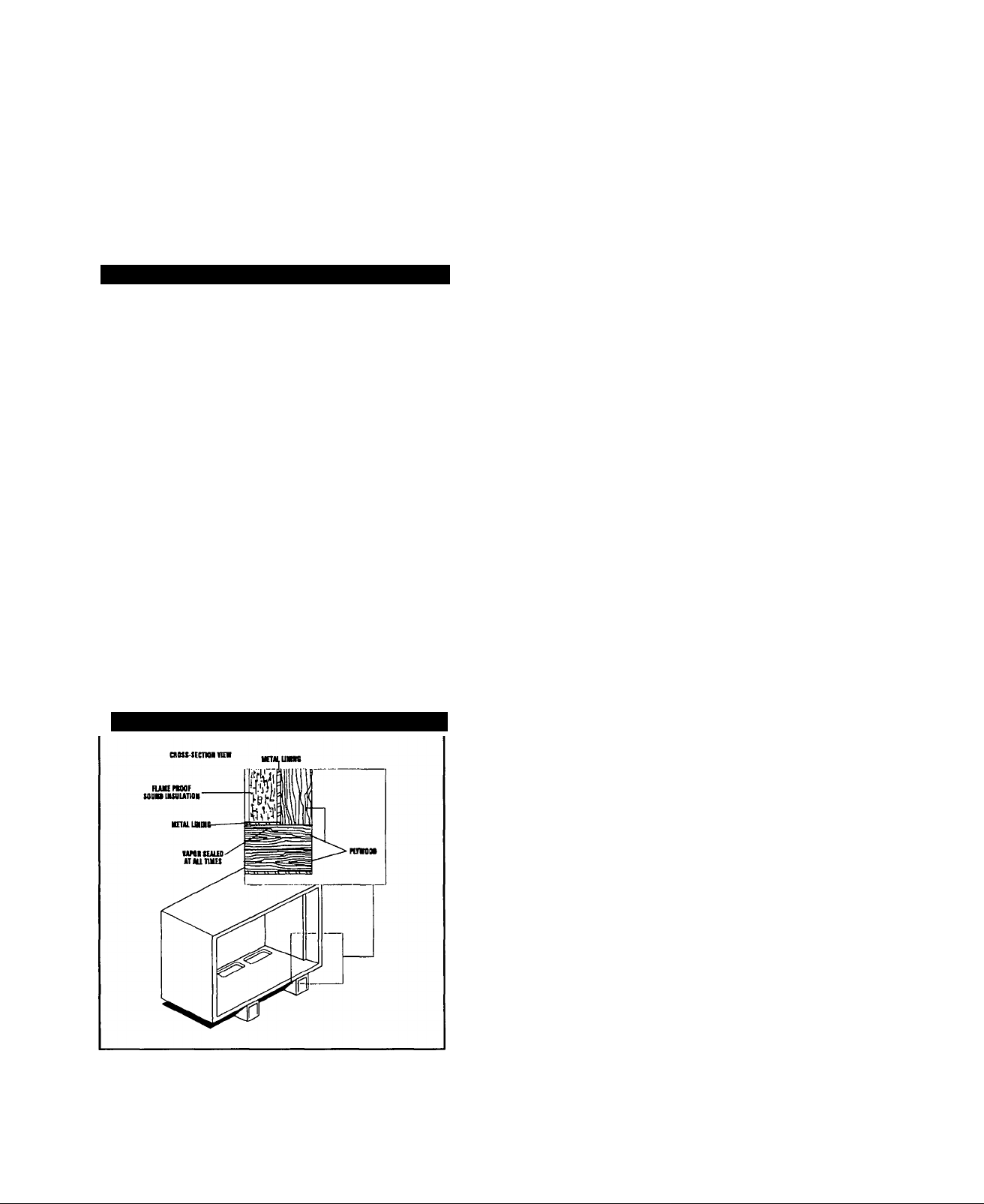
COMPARTMENT CONSTRUCTION
The generator compartment should be constructed of 1/2
inch thick plywood. Make the compartment floor a double
thickness of 1/2 inch plywood with the grain of the wood at
cross section for added strength (Figure 18).
Figure 18 — Typical Compartment Construction
DANGER: Do not install sound insulation or any
absorbent material on the compartment floor interi
or. Such materials will become soaked with combustibie or expiosive vapors and liquids and will
become a fire hazard.
• Openings in compartment walls for passage of electrical
conduit, conductors, hoses, cables, etc., must be made
vapor tight with suitable caulking material.
• Flexible conduit must be sealed internally at the end where it
terminates inside a compartment's electrical junction box!
NOTE: The preceding is required because flexible
conduit, due to its unique construction, is not vaportight along its entire length.
DANGER: Do not install any flammable material
directly above or around the compartment. Heat,
transferred through the compartment structure,
may be sufficient to ignite, char or discolor seat
cushions, fiberboard and other flammable materi
als. You may need to use approved non-flammable
insulating materials in high temperature areas.
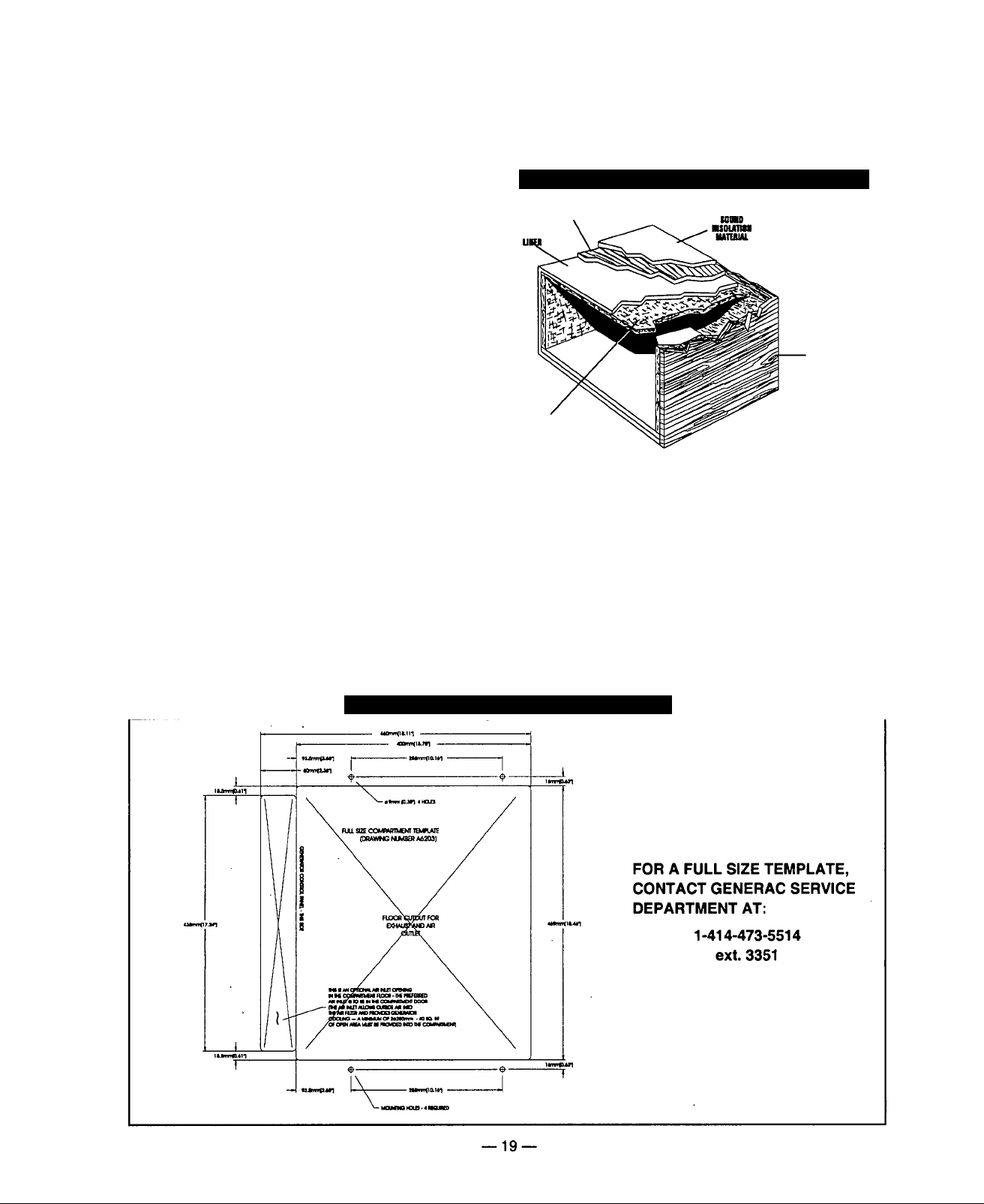
SOUND INSULATING MATERIALS
Once installers have determined that compartments
are properly constructed and metal lined, they can add
acoustical material. This may include additional
sealant or insulating material, to reflect noise away
■from the vehicle interior.
Sound insulating materials should be of a non-flamma
ble type. One excellent insulating material is a 1 inch
thick fiberglass having a 2-poundf density. When fiber
glass is used, its coated side should face toward the
compartment interior.
Using a combination of sound insulating materials can
often reduce noise more effectively than a single mate
rial. For example, a sheet of lead or visco-elastic mate
rial, along with a layer of other acoustical material, is
more effective than when a single material is used.
— 18 —
Page 21
COMPARTMENT FLOOR CUTOUTS
You must provide openings in the generator compart
ment for the following items (Figure 19):
• Engine exhaust and cooling air outlets
» Generator cooling air inlet
» Four holes for passage of generator mounting bolts. See
“Generator Restrainf on Page 17.
DANGER; Fuel lines and exhaust piping must not
penetrate into vehicle living area.
ACOUSTICS
If excessive noise levels should become a problem,
the installer may wish to consider the following:
• Using special sound insulating materials.
• Construction of a special noise abatement compartment.
IMPORTANT: ANY METHOD USED TO REDUCE
NOISE MUST NOT ADVERSELY AFFECT THE
FLOW OF COOLING AND VENTILATING AIR INTO
OR OUT OF THE COMPARTMENT.
In addition to the effective use of sound insulating
materials, construction of a special noise abatement
compartment might be considered to reduce noise lev
els. Such a compartment might be constructed as fol
lows (Figure 20):
• Use 5/8-inch thick or 3/4-inch thick plywood in the com
partment.
• Construct the compartment floor of a double thickness of
5/8-inch or 3/4-inch plywood.
• Line the compartment interior walls and floor, as well as
the underside of the floor, with 26-gauge galvanized steel.
• Vapor seal all compartment seams and joints.
Over the galvanized steel lining, install a selected combi
nation of acoustical materials as mentioned in “Sound
Insulating Materials.”
Figure 20 — Typical Noise Abatement Compartment
Nimu
(vrotwnuo)
■EOI
Fuacun
iituunoi
DANGER: Do not install any insulation or other
absorbent materials on the interior or underside of
the compartment floor.
• Seal all compartment door edges to prevent noise leakage
around the door perimeter.
• Line the compartment door interior (except for air opi
ings) with suitable, fire proof sound insulation (such
1 -inch thick fiberglass with a 2-pound density).
Exnnoi
pumoos
wnti/4'TNiao
en-
as
Figure 19 — Compartment Floor Cutout
Page 22
COOLING AND VENTILATING AIR
It is absolutely essential that an adequate flow of air for
cooling, ventilating and engine combustion be supplied
to the generator set. Without sufficient air flow, the
engine-generator quickly overheats. Such overheating
can cause serious operating difficulties and may also
cause fire and personal injury. The installer must make
sure that sufficient air is available to the generator for
cooling, ventilating and combustion. The installer must
also provide for a path for exhausting the cooling air to
the exterior of a compartment, if so equipped.
DANGER: Never use discharged cooling air for
heating or permit such air to enter the vehicle interi
or. This air contains deadly carbon monoxide gas
and other poisonous, flammable or explosive
gases.
GENERATOR AIR FLOW
Engine operation drives cooling fans for the 2-stage
cooling air system. A pressure fan draws cooling air
into the top of generator and into the side of the control
panel (Figure 21). This air flow cools the engine-gener
ator and electronic components. The second part of
cooling system, a suction fan, draws air that is heated
from a hot engine into a collector pan at the base of
the unit. This heated air (although cooler than exhaust
muffler) is directed across the muffler to cool it. The
heated air flow is then deflected out the bottom toward
the ground.
Figure 21 — Air Flow Through Engine-Generator
For conventional compartment mounted units, the air
inlet is generally provided in the compartment door.
Figure 22 — Air Inlet in Compartment Door
10 SQUARE INCHES
(OPTIONAL OPENINGS)
40 SQUARE INCHES UNRESTRICTED
(MINIMUM OPENING)
IMPORTANT: IF YOU PLAN TO INSTALL THE GEN
ERATOR IN A COMPARTMENT, BE SURE TO
LEAVE AT LEAST ONE INCH (2” RECOMMENDED)
OF CLEARANCE BETWEEN THE GENERATOR AND
COMPARTMENT WALLS AND CEILING. INCLUDE
26 GAUGE GALVANIZED STEEL LINING AND
SOUND INSULATION WHEN YOU MEASURE FOR
THIS 1 INCH (ZRECOMMENDED) CLEARANCE.
When the unit is installed on a suspended mounting
system, one of several different methods of supplying
air flow may be used as follows;
• Provide a door in the vehicle skirt having an air inlet open
ing (Figure 23).
\ /
COOLING AIR INLET OPENINGS
Ideally, you should provide three air inlet openings,
whether the generator is housed in a conventional
compartment or not. Two of the openings should be 10
square inches and located as shown in Figure 22. The
third opening should provide for a minimum of 40
square inches unrestricted and be located lower on the
compartment door.
NOTE: Screening, louvers, or expanded metal that
cover air openings restrict air flow that you must com
pensate for by making the actual air opening propor
tionately larger. See “Compensating for Restrictions.”
Figure 23 — Suspended Mount Inlet Door
be sure air is available to the top of the generator since air
inlets are located at the top.
By providing an opening in the vehicle skirt and space
above the generator for cooling air flow (Figure 25 on Page
21). Recommended clearance above the top of the gener
ator is at least 2 inches.
-20-
Page 23
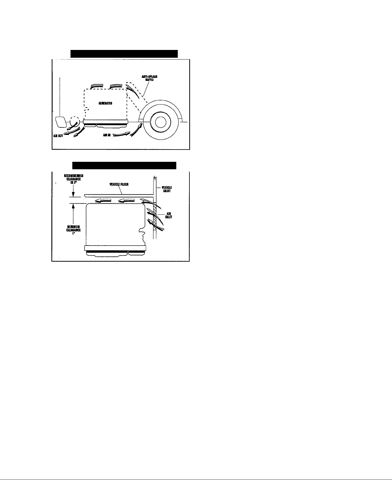
Figure 24 — Air Inlet Using Ductwork
Figure 25 — Air Inlet in Vehicle Skirt
COMPENSATING FOR RESTRICTIONS
Such materials as screening, louvers, or expanded
metal can restrict the free flow of air. Compensate for
this restriction by making the actual air opening propor
tionately larger.
Some materials may offer only a 60 percent “free air
inlet area.” Other more efficient materials may provide
up to a 90 percent free air inlet area. The percentage
of free air inlet opening is usually available from the
material supplier or manufacturer.
TO DETERMINE THE ACTUAL AIR INLET OPENING
SIZE REQUIRED, DIVIDE 40 SQUARE INCHES BY
THE PERCENTAGE OF FREE AIR INLET AREA
FOR THE MATERIAL YOU WILL USE.
For example: If you plan to use screening with an 80%
free air inlet area, divide 40 by 0.8, which results in 50
square inches. Minimum actual size of air inlet opening
in this case is 50 square inches. An opening that mea
sures 4 inches wide by 12-1/2 inches long provides the
required air flow (4 x 12.5 = 50 square inches).
TESTING THE INSTALLATION
Generac recommends testing the installation to be
sure adequate cooling air flow is available to the unit
before placinq the unit into service. If the unit shows
signs of overheating, you will need to enlarge the air
openings. Never place a unit into service until
absolutely certain that cooling and ventilation is ade
quate.
IMPORTANT: YOU MUST TEST THE INSTALLATION
ESPECIALLY IF YOU BRING IN AIR FROM BELOW
THE GENERATOR SET.
— 21 —
Page 24
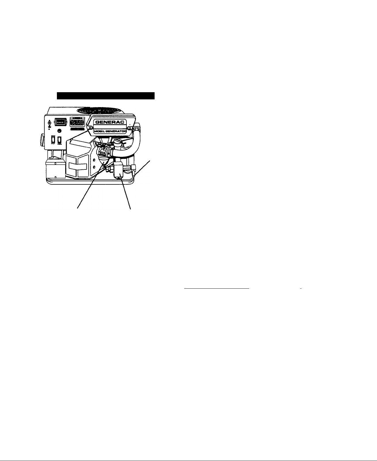
GASOLINE FUEL SYSTEM
Installing a gasoline fuel system (Figure 26) for recre
ational vehicle generator sets must comply with applic
able codes, standards and regulations. The entire fuel
system must be completely free of leaks. There must
be no possibility of gasoline vapors entering the vehi
cle interior.
Figure 26 — Generator Fuel System
FUEL INLET
CARBURETOR
DANGER; Gasoline is highly flammable and its
vapors are explosive. Compiy with all codes, stan
A
dards and regulations pertaining to gasoline fuel
systems used in mobile generators. Properly install
and maintain the fuel system and keep it entireiy
free of ieaks. Gasoline vapors must not enter the
vehicle interior.
FUEL PUMP
CAUTION: Do NOT tee the generator fuel supply line
into the vehicle engine fuel supply line. If this is
done, the generator wiil be starved of fuei when
both engines are operating at the same time. Aiso,
whiie the vehicie engine is not running, generator
operation may drain the vehicle engine suppiy iine,
making it difficuit to start the vehicle engine.
GENERATOR FUEL SUPPLY LINE
RIGID FUEL LINES
Those lines used to supply fuel from a tank to the gen
erator must comply with applicable codes, standards
and regulations. The following generator rules apply to
rigid fuel lines:
• Rigid lines should be of annealed, seamless, drawn alu
minum or steel.
• Lines and fittings must comply with SAE J512F, “Standard
Automotive Fittings”, or with ANSI B126.26 (latest edition).
• Route the fuel line so that at least 2 inches of clearance is
maintained between the line and any exhaust system
parts.
• Do not attach electrical wiring to fuel lines. Route the
wiring so it cannot come into contact with any fuel line.
• Route fuel lines so if they leak, fuel does not drip onto any
electrical or exhaust system parts.
• Use non-ferrous metal straps without sharp edges to
secure fuel lines.
Factory installed generator fuel system components
include (a) fuel filter, (b) 12-volt DC electric pump, (c)
engine carburetor, and (d) interconnecting lines and fit
tings. Connect a fuel supply line to the fuel filter inlet.
Use a flexible length of approved fuel hose between
the fuel filter inlet connection and rigid fuel lines.
FUEL TANK
Either the generator must share the vehicle engine's
fuel tank, or you must install a separate fuel tank for
the generator set. All fuel tanks installed on the vehicle
must be constructed, installed, restrained so it com
plies with applicable codes, standards and regulations.
If the generator is to share the vehicle engine's tank,
separate fuel pickup tubes are required for the engine
and the generator. Generac recommends that you
make the fuel pickup tube 2 to 3 inches shorter than
the vehicle engine's pickup tube. This prevents the
generator from depleting the entire fuel supply during
prolonged generator operating periods.
— 22 —
■ FLEXIBLE FUEL LINE
Use an approved flexible length of fuel hose between
the generator fuel inlet connection and rigid fuel lines.
This prevents breaking of the line caused by vibration,
shifting, settling or movement. The following rules
apply:
• The flexible hose must comply with SAE J30B, “Standard
for Fuel and Oil Hose”. It must be approved for use with
gasoline.
• The hose should be at least 6 inches longer than is need
ed to prevent the hose from rupturing if the generator shifts
or settles.
______________
'
Page 25
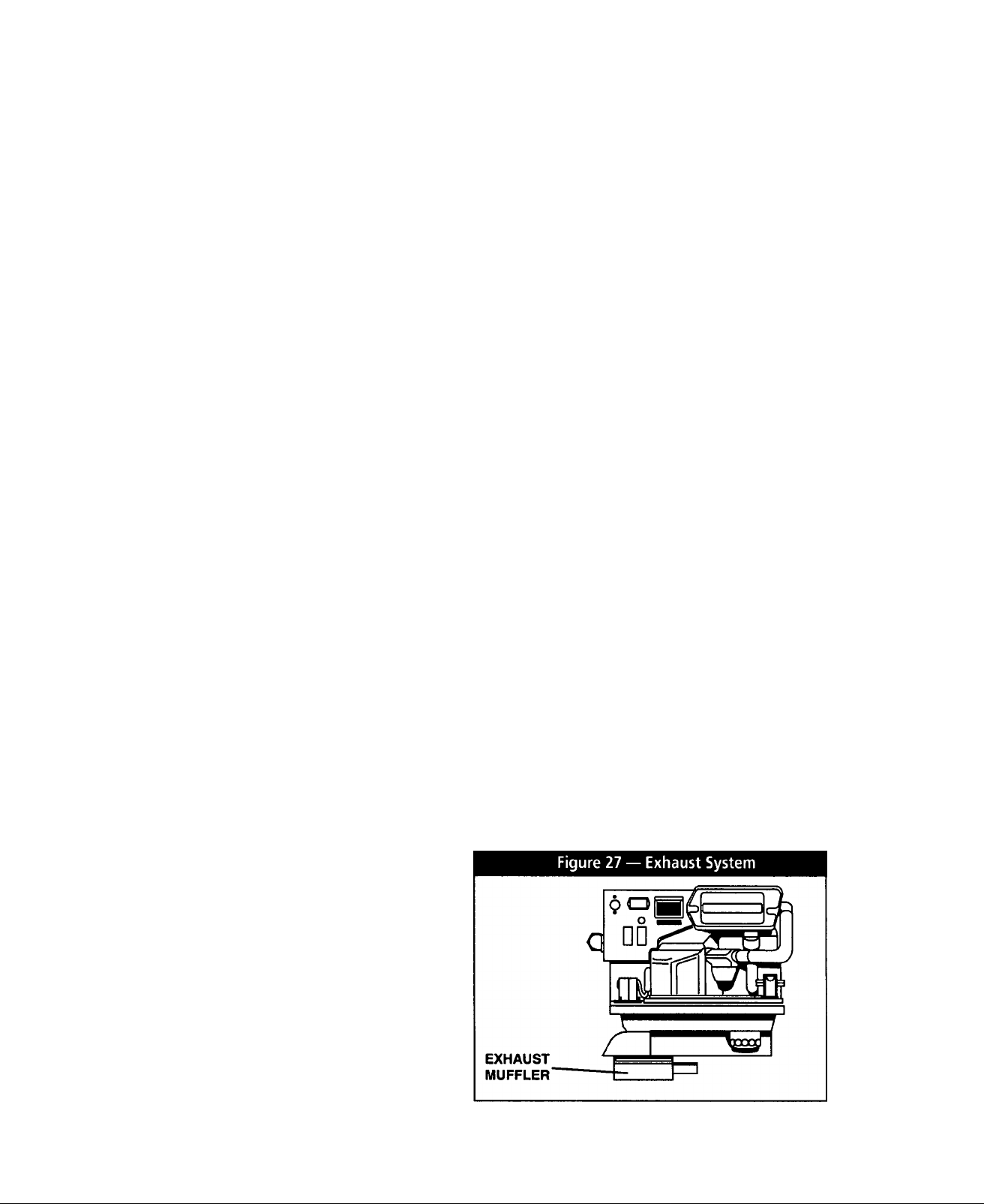
EXHAUST SYSTEM
The generator exhaust system must be safely and
properly installed. Only approved mufflers and other
exhaust system parts must be used. A properly
installed exhaust system must be vapor tight, quiet and
completely safe.
CAUTION: Never tee the generator engine exhaust
pipe into the vehicle engine exhaust piping. This
causes excessive back pressure on the generator
engine. Aiso, water from one engine can damage
the other engine.
DANGER: The generator engine gives off deadly
carbon monoxide gas through its exhaust system.
This dangerous gas, if breathed in sufficient con
centrations, can cause unconsciousness or even
death. Symptoms of carbon monoxide poisoning
are (a) inability to think coherency, (b) vomiting, (c)
twitching muscles, (d) throbbing in temples, (e)
dizziness, (f) headache, (g) weakness and sleepi
ness. If any of these symptoms are experienced,
move into fresh air immediateiy. If symptoms per
sist, get medical attention. Do not operate the gen
erator until its exhaust system has been inspected
and repaired.
MUFFLERS AND SPARK ARRESTORS
Exhaust mufflers and spark arrestors that Generac
supplies meet code and standard requirements, and
are approved by the U.S. Forest Service. Use only
mufflers and parts approved by Generac. Any
person(s) installing an unapproved muffler, or an unap
proved exhaust system part, or modifying an exhaust
system in any way that might cause a hazard, is liable
for any damage, injury or warranty expense that might
be caused by such unapproved installation or modifi
cation.
Failure to provide and maintain a spark arrestor may
be in violation of the law. If this generator is used on
any forest covered, brush covered, or grass covered
unimproved land, you must provide a spark arrestor.
The vehicle owner or operator must maintain this
device in good condition. In the State of California, the
preceding is required by law (Section 4442 of the
California Public Resources Code). Other states may
have similar laws. Federal laws apply on federal lands.
EXHAUST SYSTEM SAFETY
Maintain a clearance of at least 3 inches (76mm) between
exhaust system parts and any combustible material (such
as wood, felt, cotton, organic fibers or other like material).
If you cannot maintain the 3-inch clearance, locate, insu
late or shield the exhaust part(s) so that the temperature of
any combustible material is not raised more than 117°F
(65°C) above the ambient air temperature.
Extend the exhaust system at least one inch (25mm) past
the outer edge of the vehicle. Do not terminate the exhaust
system under the vehicle.
Terminate the exhaust tailpipe such that exhaust gases will
not be drawn back into the generator compartment and
recirculated.
If there is any possibility of the tailpipe or muffler being
damaged, protect these damage prone areas by means of
a protective device (such as a “skid bar”).
Install the generator exhaust system according to safe
automotive practices.
Use enough exhaust system hangers to prevent any part
of the system from being dislocated.
Use exhaust system parts recommended by Generac.
Using unapproved exhaust mufflers and exhaust system
parts is the responsibility of the person(s) installing such
unauthorized parts.
Do not terminate the exhaust system under any opening,
window or vent which can be opened or is not permanently
sealed from the vehicle interior.
Exhaust piping must be large enough to prevent excessive
back pressure on the generator engine.
Never tee the generator engine exhaust pipe into the vehi
cle engine exhaust piping. This causes excessive back
pressure on the generator engine. Also, water from one
engine can damage the other engine.
Plan exhaust system installation carefully. Comply with all
applicable codes, standards and regulations.
TYPE OF EXHAUST SYSTEM
The lmpact-36G generator has a configuration for a
bottom out exhaust system and is equipped with such
an exhaust muffler (Figure 27).
— 23 —
Page 26

ELECTRICAL CONNECTIONS
Be sure to read “Generator AC Connection System” on
Page 4.
The following general rules apply to electrical connec
tions in a recreational vehicle:
• Qualified electricians who are familiar with applicable
codes, standards and regulations should install electrical
wiring.
• The wiring should comply with codes, standards and regu
lations. The National Electric Code (NFPA 70), as well as
state and local codes, apply.
• Switches and circuit breakers should be of a type approved
for use in recreational vehicles and must be mounted and
■ installed to prevent damage from road shock.
• Wiring must be of adequate size, with approved insulative
qualities, and properly supported.
• Conduit and wire openings into generator compartment (if
used) must be vapor-sealed, to prevent entry of flamma
ble, explosive or poisonous gases into the vehicle.
ELEamCAL JUNCTION BOX
Install an approved, square electrical junction box that
has a blank cover on the interior or exterior wall of the
area you plan to install the generator (NOT on the gen
erator). Route the generator's AC output leads into this
junction box through approved flexible conduit, and
into this junction box. This is the point of first termina
tion for generator AC output leads.
• Conductors must be rated 221°F (105°C) or must be of a
larger conductor size.
GENERATOR AC CONNECTIONS
Generator AC output leads T1 (black) and T2 (white)
come out of the generator as shown in Figure 28. Lead
T1 (black) is “hot.” Lead T2 (white) is the “neutral” lead
and is internally connected to ground. The green lead
(0) connects to ground in the junction box of the recre
ational vehicle.
Figure 28 — Generator AC Output Leads
Line T1 (black) is protected against overload by the cir
cuit breaker (CB1). Use line T1-T2 to operate 120
volts, 1-phase, 60 Hz, AC loads.
WIRING
• Wiring should be of stranded copper to reduce chance that
vibration may cause breakage.
• Wire gauge size of wires should be large enough to handle
at least 115% of the installed generator's rated maximum
current.
• If neutral conductors are used, they must be the same size
as other leg wires.
• Route power supply conductors from generator AC output
leads T1 (black) and T2 (white) and the green ground wire
through approved flexible conduit to the electrical junction
box on the compartment wall.
• If flexible metal conduit is used between the generator and
the compartment junction box, the conduit end that termi
nates the compartment junction box, must be vaporsealed. Flexible metal conduit is NOT vapor tight along its
entire length.
• From the junction box route power supply wires through
approved conduit to either (a) double-pole, double-throw
transfer switch, or (b) approved isolation receptacle.
Connecting to a transfer switch or isolation receptacle
must prevent vehicle electrical circuits from being connect
ed to two different power supplies at the same time (such
as generator and dockside power).
CAUTION: Do NOT connect electrical loads in
excess of any circuit breaker rating or you will
develop problems with circuit breaker tripping,
which causes a loss of AC output. Also, do NOT
exceed the generator's rated wattage capacity. Add
the watts or amperes of all lighting, appliance, tool
and motor loads the generator will operate at one
time. This total should be less than the unit's rated
wattage/amperage capacity.
CONDUIT
Route the conductors between the generator and the
junction box through approved, flexible conduit. The
following general rules apply:
• Cut wiring to the required length and allow extra wire for
junction box connections.
• Carefully prepare conduit ends, to prevent sharp edges
from cutting through wiring insulation.
• Route conduit so it does not interfere with generator move
ment.
• If you use metallic conduit, vapor seal the end of the con
duit where it enters the junction box. Do this because flexi
ble metallic conduit is not vapor proof along its entire
length.
— 24 —
Page 27

ISOLATING DIFFERENT
GROUND FAULT CIRCUIT
POWER SOURCES
Conductors from the junction box must terminate in a
double pole, double throw transfer switch (Figure 29).
An aiternate method for isolating different power
sources is by using an isolating receptacle (Figure 30
on Page 26). Whichever method you use, you must be
certain that both power sources are NOT connected at
the same time.
POWER SUPPLY CORD
The power supply cord must comply with all applicable
codes, standards and regulations. It must be large
enough to handle the full amperage to which it will be
subjected.
Figure 29 — Transfer Switch Isolation Method
INTERRUPTERS
The National Electric Code (NFPA 70, 551-7) requires
that you install ground fault circuit interrupters (GFCIs)
on all external and some internal electrical receptacles.
Contact your manufacturer or dealer for recommenda
tions.
— 25 —
Page 28

Figure 30 — Installation with Isolation Receptacle
BATTERY INSTALLATION
RECOMMENDED BAHERY
Install a battery that meets the following requirements:
• Battery must be a 12 volt, automotive type storage battery.
• For prevailing ambient temperatures above 32°F (0°C),
use a battery rated 70 amp-hours and capable of deliver
ing 360 cold cranking amperes.
• For prevailing ambient temperatures below 32°F (0°C), use
a battery rated 95 amp-hours and capable of delivering
450 cold cranking amperes.
IMPORTANT: IF THE BATTERY IS TO BE USED TO
POWER OTHER VEHICLE ACCESSORIES, AS
WELL AS START THE GENERATOR. YOU MAY
NEED A BATTERY WITH A LARGER CAPACITY.
BAHERY CABLES
Using battery cables that are too long or too small in
diameter may cause a drop in voltage which causes
starting problems. For best cold weather starting, the
voltage drop between battery terminals and the gener
ator connection point should not exceed 0.12 volts per
100 amperes of cranking current.
Select battery cables based on (a) cable length, and
(b) prevailing ambient temperatures. Generally, the
longer the cable and the colder the weather, the larger
the cable size must be as shown in the chart below.
CABLELENGTH
In Feet (meters)
Oto 10 (0 to 3)
11 to 15 (3.4 to 4.5) 0
16 to 20 (4.5 to 6) 000
*For warm weather, use No. 2 cable up to 20 feet.
•26-
CABLE SIZE
2*
Page 29

I
BAHERY CABLE CONNEaiONS
1. Connect the battery cable from the battery post or terminal
indicated by a POSITIVE, POS or (+) to the large lug on
the starter contactor as indicated in Figure 31.
2. Connect the battery cable from the battery post indicated
by a NEGATIVE, NEG or (—) to the frame ground connec
tion (Figure 31).
NOTE: If the generator compartment is grounded to
the vehicle chassis, you need not connect a NEGA
TIVE battery cable to the frame ground on the genera
tor base. Connect the negative cable to the frame
ground of the chassis.
3. Connect cables so the connections are clean and tight.
Figure 31 — Connecting Battery Cables
BAHERY COMPARTMENT
Install the generator battery in its own, vented com
partment. Place the battery compartment away from
any source of heat, sparks or flame.
Provide ventilation openings in the battery compart
ment. The minimum size of openings should be 2
square inches at the top of the compartment. Mount
the battery on a strong, rigid supporting structure,
where leaks and spills of battery fluid will not cause
damage.
27 —
Page 30

OPTIONAL ACCESSORIES
A plug-in receptacle (Figure 32) is provided on the
generator set, near the AC connection wires. Use this
receptacle to connect an optional remote-mounted
start/stop panel to the generator. Installation of such a
panel will permit you to start and stop the generator
engine from any convenient location inside the vehicle.
Figure 32 — Remote Panel Plug-In Receptacle
REMOTE PANEL MODELS
Model 9042: This remote panel (Figure 33) mounts a
rocker type start/stop switch and a “Generator Run”
advisory lamp. The lamp will turn on to indicate the
engine is running.
Model 9043; This panel mounts a rocker type switch, a
“Generator Run” lamp and an hourmeter (Figure 34).
Use the hourmeter in conjunction with the periodic
maintenance schedule for your generator.
Figure 34 — Model 9043 Remote Panel
o o
GENERAC R.V. GENERATOR
REMOTE PANEL CABLES
Interconnection cables are available from Generac for
connecting the optional remote panels to the generator
receptacle.
• To order a 10-foot long, 4-wire cable, specify Model 9045.
• To order a 30-foot long, 4-wire cable, specify Model 9046.
Figure 33 — Model 9042 Remote Panel
©
GEIMERAC
R.V.
GENERATOR
— 28
Page 31

POST INSTALLATION TESTS
The air cooled generator set was factory tested and
adjusted using gasoline as fuel. You should not be
required to adjust the unit any further except under
special circumstances.
WARNING: Do not make any unnecessary adjust
ments. Factory settings are correct for most appli
cations. When making adjustments, however, be
careful to avoid overspeeding the engine.
BEFORE INITIAL START UP
Before starting, complete the following:
1. Check engine crankcase oii ievei and, if necessary, fili to
dipstick FULL mark with the recommended oil. Do not fill
above FULL mark.
2. Check the fuel supply. Gas fuel lines must have been prop
erly purged and leak tested in accordance with applicable
fuel codes. All fuel shutoff valves in the fuel supply lines
must be open.
DANGER: If an LP (propane) gas fuel system has
been installed, it must have been properly tested for
leaks before operating the system in compliance
with ANSI 119.2/NFPA 501C. No leakage is permit
ted. You must be sure no gaseous fuel vapors
enther the vehicle Interolr.
INITIAL START
When absolutely certain that the unit has been proper
ly installed and prepared for use, start the engine as
follows:
1 .Turn off all electrical loads. Do this by setting the generator
main circuit breaker to its "OFF or “OPEN” position.
2. Refer to the Owner's Manual shipped with unit for cranking
and starting instructions. The engine may require more
cranking for initial starting since the fuel lines have to be
primed (Use of the Primer Switch will shorten this time).
3. Let the engine warm up for about five minutes to allow
internal temperatures to stabilize.
4. Carefully inspect the engine-generator for fuel, oil and
exhaust system leaks. Before proceeding to the next step,
correct any leakage immediately.
5. When all tests and adjustments at no-load are completed,
apply electrical loads and check for proper operation under
load. See ‘Testing Under Load”. Run the unit at least 30
minutes with loads applied.
6. Turn off all electrical loads by setting the generator main
circuit breaker to “OFF or “OPEN.”
7. Let the unit run at no-load for a few minutes to stabilize
internal engine-generator temperatures. Then, shut down
the engine.
IMPORTANT: THE GENERATOR SET WAS THOR
OUGHLY TESTED AND ADJUSTED AT THE FACTO
RY BEFORE SHIPPING. NO ADDITIONAL ADJUST
MENT SHOULD BE NECESSARY. ONLY QUALIFIED
SERVICE TECHNICIANS WHO HAVE BEEN
TRAINED SHOULD PERFORM ADJUSTMENTS
OUTLINED IN THIS MANUAL.
TESTING UNDER LOAD
Apply electrical loads equal to about 75-100% of the
unit's rated wattage/amperage capacity.
Let the unit run at least 30 minutes with load applied.
During this part of the test, check that the unit is not
running excessively hot and that adequate cooling air
flow is available. You must not allow the unit to over
heat during prolonged operation.
NOTE: The generator engine is equipped with a high
temperature switch. The switch has normally-open
(N.O.) contacts. When the temperature is too high,
switch contacts close, and engine shuts down auto
matically.
IMPORTANT: GENERAC RECOMMENDS THAT YOU
TEST THE GENERATOR FOR ADEQUATE COOL
ING.
— 29 —
Page 32

INSTALLATION CHECK LIST
LOCATION AND SUPPORT EXHAUST SYSTEM
_1. The generator is properly located.
_2. The generator is properly supported.
_3. The generator is properly restrained.
COMPARTMENT
___
1. Compartment construction is proper.
___
2. Holes/openings are vapor-sealed.
___
3. Compartment size is correct.
___4. Compartment is vapor-sealed.
___
5. Sound insulation is O.K.
___
6. Floor cutouts properly completed.
COOLING and VENTILATING AIR
___
1. Air flow is adequate.
___
2. Air inlet opening is correct.
___
3. Compensate for restrictions
4. Installation has been tested
___
1. Complies with code requirements.
___
2. Properly and safely installed.
ELECTRICAL CONNECTIONS
___
1. Comply with code requirements.
___
2. Junction box properly installed.
___
3. Wiring meets all standards.
___
4. All connections are correct.
___
5. Conduit properly installed and sealed.
___
6. Generator properly bonded to vehicle.
BATTERY INSTALLATION
___
1. Recommended battery is installed.
___
2. Recommended cables are installed.
___
3. Cables are clean and tight.
___
4. Cables are properly connected.
___
5. Proper ventilation is provided.
POST INSTALLATION TESTS
___
1. All tests properly completed.
GASOLINE FUEL SYSTEM
___
1. Fuel tank complies with code.
___
2. Fuel system properly installed.
DATE OF INSTALLATION
NAME OF INSTALLER
SIGNATURE OF INSTALLER
OPTIONS AND ACCESSORIES
Check that remote start/stop panels (if used) are prop
erly installed.
If an hourmeter kit is installed, check that job was done
properly.
If any other options and accessories are installed,
check that they were installed properly.
— 30 —
Page 33

TROUBLESHOOTING
PROBLEM
Engine won't crank. 1. 15 amp fuse is blown
Engine cranks but won't start. 1.
Engine starts hard, runs rough, 1. Air cleaner plugged or damaged
low full load power. 2.
Engine starts, shuts down
when Start/Stop switch is 2. Engine is overheated.
released. 3.
POSSIBLE CAUSES
2. Loose corroded or defective 2. Tighten, clean or replace
battery cables.
Defective engine Start/Stop switch. 3. Replace Start/Stop switch.
3.
Defective starter contactor. 4.
4.
Defective starter motor. 5. Replace starter motor.
5.
Low or defective Battery 6. Charge or replace battery.
6.
Out of fuel. 1. Replenish fuel.
2. Fuel pump is defective.
Open Wire #14 from Eng. Control Bd.
3.
4. Engine is flooded.
Spark plug defective. 5.
5.
Defective spark plug. 2.
Loose spark plug boot. 3. Press boot on securely.
3.
1. Engine oil is low. 1.
Defective Low Oil Pressure System 3.
4. Defective Engine Control Board
Defective Computer Control Board 5. Have board serviced/replaced.
5.
REMEDY
1.
Replace 15 amp fuse
as necessary.
Replace contactor.
2.
Replace fuel pump.
3. Reconnect wire.
4.
Wait 5-10 min. before trying.
Clean, regap or replace plug.-
1.
Clean or replace as needed.
Clean, regap or replace plug.
Check oil; add as needed.
2.
Check adequate ventilation.
Have serviced/replaced.
4.
Have board serviced/replaced.
Start/Stop switch at Stop,
engine continues to run. 2. Open/disconnected wire #18 between
No AC output from generator.
•
1. Defective Start/Stop switch 1.
Start/Stop switch and Engine Control
3. Open/disconnected wire #0 between
Start/Stop switch & Engine Control Bd.
4. Defective Engine Control Board
Check circuit breaker. 1. Reset to ON or CLOSED.
1.
2. Check vehicle circuit breaker & fuses. 2. Reset and replace if necessary.
3. Transfer sw. set to NORMAL position. 3.
4. Generator internal failure 4.
Replace switch.
2. Reconnect or close wire.
Reconnect or close wire.
3.
4.
Replace board.
Set to GENERATOR position.
Take generator to an
Authorized Generac facility.
— 31 —
Page 34

NOTES
32 —
Page 35
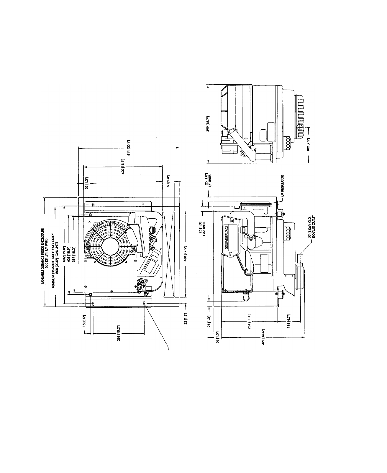
MAJOR FEATURES AND DIMENSIONS
33 —
Page 36
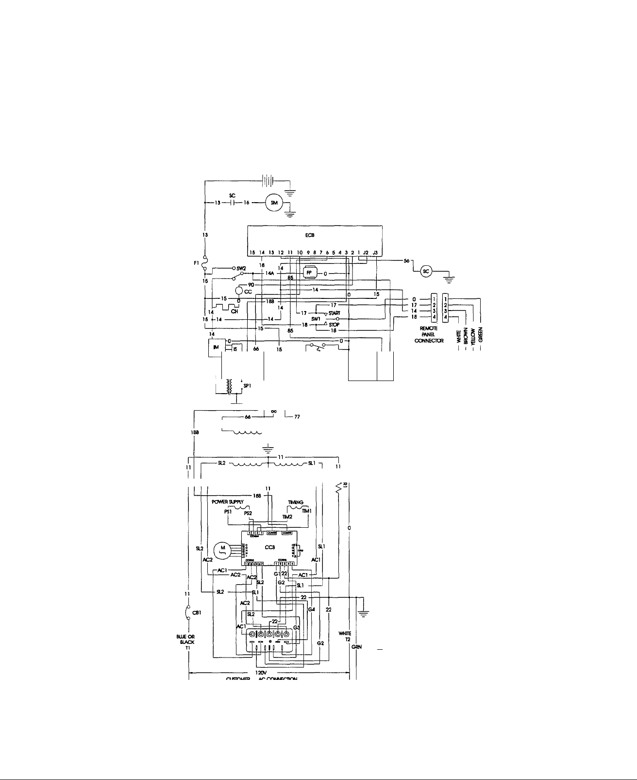
ELECTRICAL DATA
Drawing No. A2420 Rev. A
CUSIOMS) SIPPUEO
BMTrERY
C >BB
^ 8AITBiYCHA«GEWN0WG ”
R2> “
65
POVB? V^ING
Fa
rof
REMOTE PANEL
(OPTIONAL)
BCR • aAITBrr CHARGE RECTR8)
CB1 > CSKXHT BREA№)
CC -CHOtSCOl
CC& - COMPUTB^ CONmCX BCMIO
CH - CHOti£ HEAIBt
EC8 • ENGINE CONTROL BOPO
FI -FUSE.16A
P - FUa PIM> ON GASOLf€
G -GENtSTOR
HM -HOUR№TER
HTO • SVWCH HGH TEM>5W\JRE 0(L
C -IGNmONCOL
M • IGNmON MOOUIE
B • (GNDON SENSOR
L1 < UGHT. RUN (OPTIONAL)
iOP - SMTCa ICW OIL PRESSURE
M - STB>P6i MOTOR THiOTTlE CONTROL
R1 -R£SBTOa6000HM.60WAnS
R2 - T OHM. 60 WATTS
SC • SMTTBT CONMCTOR
SM - STARTER MOTOR
SWT • S'MTOt START/SIOP
SW2 • SWTTOi Rja PUMP PRM
SPT-SPARKPLUG
■C3- -LUG.BARRa
TO -TB»ylNAL CONTACTOR 4 lAa
Fa • TIME OBA!^ FflJER
\£GBC
SHUFOFF VMVE ON l/P
(CLOSES ON HGH TEM>BMnjR£]
(OPENS ON I4GH PRESSUS)
CUSTOMS? ACCOATCCTTON
— 34 —
Page 37
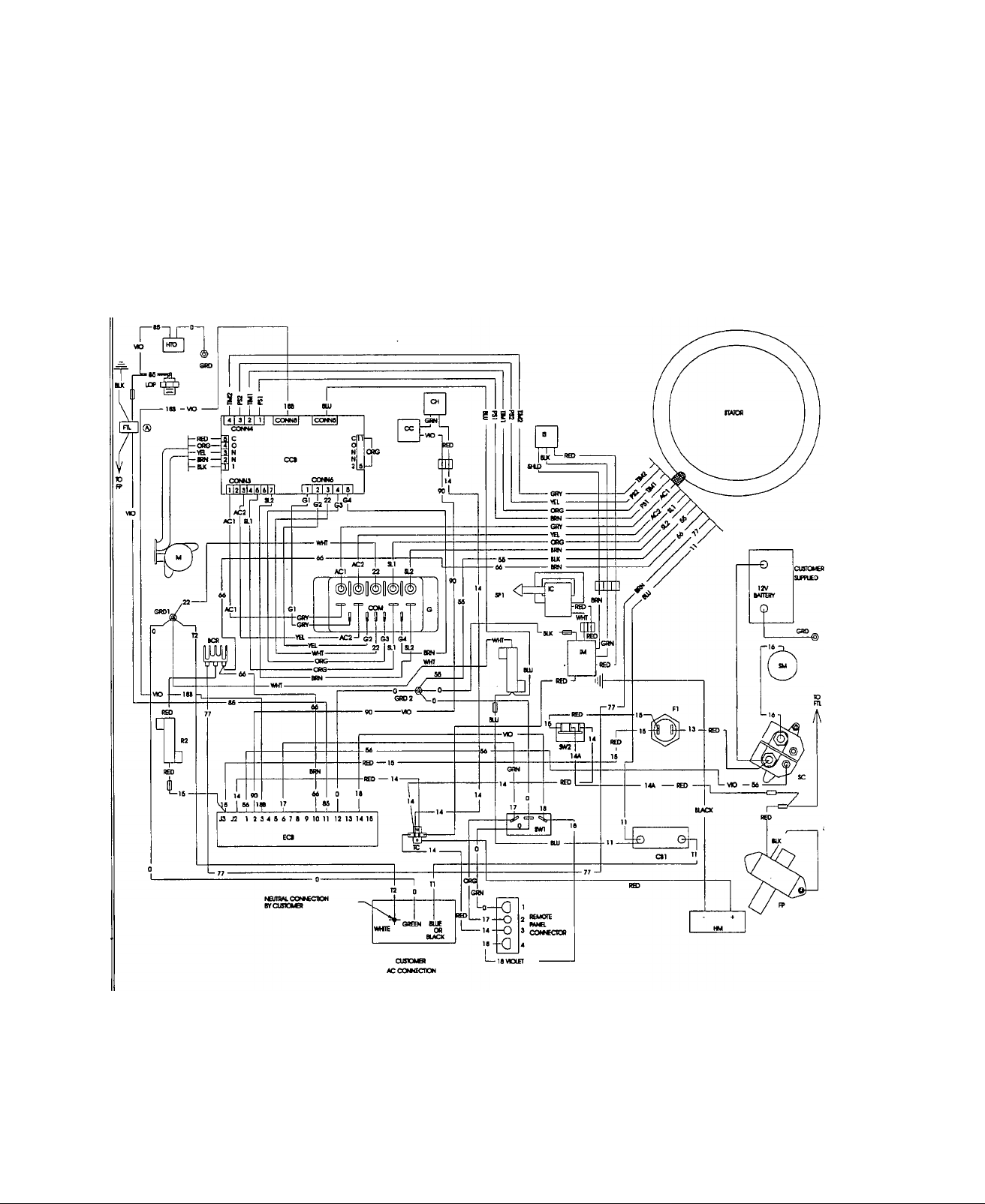
Drawing No. A2420 Rev. A
ELECTRICAL DATA
-35-
Page 38
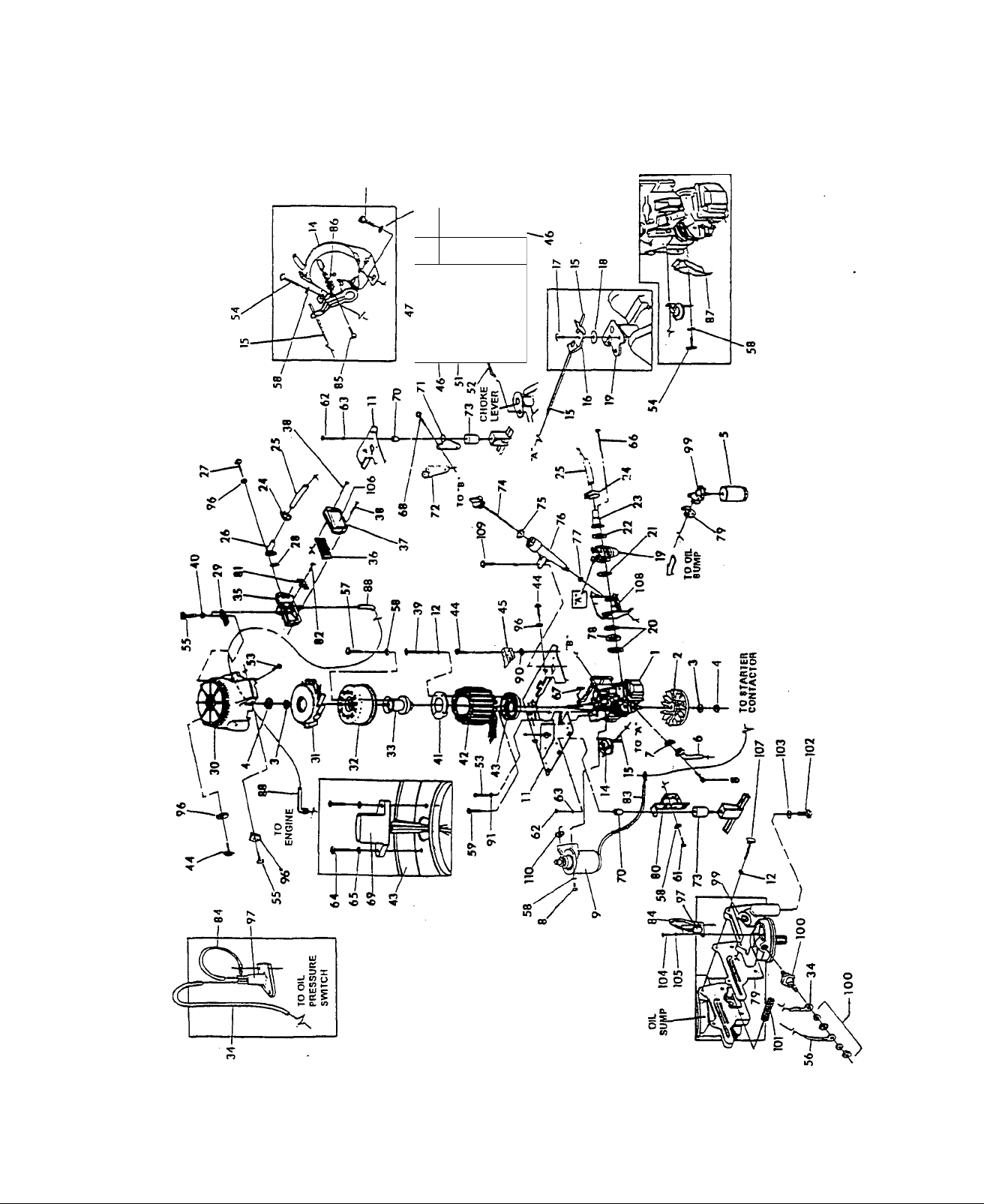
EXPLODED VIEW — GENERATOR
Drawing No. A5969 Rev A
o -e
f A
s
\ r/^~ \
— 36
Page 39

I
REPAIR PARTS — GENERATOR
Drawing No. A5969 Rev. A
ITEM PARTNOl.. DESCRIPTION
1 A2467
2 94583
3 83312
4
81810
5 70185
6 86730
89476 • 1 GASKET, EXHAUST 61 39253 3 HEX HD. CAPSCREW,
7
8 40976
99948
9
11 86705
12 22097 8 LOCKWASHER, 1/4”-M6
14
92059
15 86706
89477 1 CLIP, ADJUSTMENT
16
17 89478
90192
18
90881A 1
19
20 90051
21
22 96459
25
26 87993
28 90536
49 91306 1 SOLENOID, CHOKE
50
78631
86709 1 ADAPTOR, CARB. INLET 76
23
24 35586
86710
27
49815
29 90021
30 94665
93859 1 FAN, GENERATOR
31
32 A5892
91437 1 HUB, MAGNET HOUS. ASSY. 87 92800 1
33
34 003-91297
35 86673
36 78601
86674
37
38 78609
39 66449C
40 49226
41 80934 1
42 A5898
86692 1
43
44 74908 3 TAPTITE, M5-0.8X 10MM 102 52617
45 86735 1 COVER, CHOKE MOUNT
46 47488 4 SCREW, 4-40 X. 188” 103
47
22159 4
48 31879 4
36544 1
51 89473
52 86736 1
53 45756 3
54
83512
1
2
2
1
1 TUBE, EXHAUST OUTLET
4 SOCKET HD. CAPSCR., M8-1.25X20MM
1
1
1
1 ROD, THROTTLE CONTROL 67 82774
1
1
2 GASKET, 71 86701 1 BRCKT., ENG. MNT. FRONT
1
1
2
1
1 . ELBOW, AIR CLNR. OUTLET
2 HEX HD. CAPSCREW,
1 GASKET, AIR CLEANER
1
1
1 ASSY., MAGNET HOUSING
1
1
1 ELEMENT, AIR FILTERV
1
2
1
1
1
ENGINE, LONG BLOCK 55 52618
FLYWHEEL, FAN
WASHER, CONICAL
HEX NUT, Ml6-1.5
FILTER, OIL
M8-1.25X20MM
STARTER, EATON/GENERAC 3/8”-16X 1.25”
PLATE, DIVIDER
STEPPER MOTOR SPEED 65
CONTROL 66 89050
SNAP, RETAINING 68
WASHER, CARBURETOR 69
ASSEMBLY., CARBURETOR
CARB./SPACER/HEAD
GASKET, CARB./SKIRT 73
GASKET, CARB./INLET
ADAPTOR 75
HOSE CLAMP-BAND 1.50”
HOSE, CARB. INLET 78 86708 1
M5-.8X 16MM
OUTLET
BRACKET., AIR CLEANER 82 59635
SUPPORT
HOUSING, FAN-UPPER
TEMP. SWITCH WIRE
BASE, AIR BOX 90 23762
COVER, AIR BOX 91
BOLT, AIR CLNR. COVER SHAKEPROOF - .25"
4 HEX HD. CAPSCREW, 94 23484P
M6-1 X 80MM 96 23897
4
LOCKWASHER, M5
RETAINING RING, STATOR 99 86675A 1
ASSEMBLY STATOR
ADAPTOR, STATOR 101 86714 1
LOCKWASHER - #4
FLATWASHER - #4
PIN, COTTER 3/32” X 1/2” 107 A8617
ASSY., BI-METAL & HEATER 108 86726 1 SKIRT, BAFFLE
LINKAGE, CHOKE CONT. 109 56893 1
M6-1 X 10MM TAPTITE 110
TAPTITE M8-1.25 X 15MM
ITEM PART NO.
56 005-91297
57 42907 3 HEX HD. CAPSCREW,
58 22129 10
59
62 22511 3 HEX HD. CAPSCREW,
63
64 55822 2 PHMS, M4-.7 X 8MM
74 89263 1 ASSY., OIL FILL CAP
79 87478
83
100
104 70728
105 43182
106 A1627 1
74906
22237
22264 2
59637
86697 1
86704 3
70
72 86702 1 BRCKT., ENG. MNT. REAR
38353 3
90071 1 0-RING, 1.062" I.D.
94637 1
77
90072
96627 1
80
81 90613
002-91297 1
84
004-91297
59636
85
88905 1
86
89062 1
88
22447
97
94090 1 SWITCH-THERM., OIL TEMP.
77667
94643 1 GASKET, OIL DRAIN PLUG
A9257
QTY. DESCRIPTION
5
M5-0.8X 12MM CPSCR.
1
• OIL PRESS. SWITCH WIRE
M8-1.25X 16MM
LOCKWASHER - M8
4
M6-1 X 20MM TAPTITE
3
LOCKWASHER - 3/8”
LOCKWASHER - M4
2
PPHMS - M6-1 X 90MM
1
WOODRUFF KEY4MMX 19MM
4
TAPTITE 3/8”-16 X .75"
ASSY. IGNITION SENSOR
SPACER, ENGINE MOUNT
RUBBER MOUNTS
OIL FILL TUBE
1
0-RING .562” I.D.
CARBURETOR SPACER
1
GASKET, OIL FILTER
ADAPTOR
BRACKET, STARTER SIDE
ENGINE MOUNT
1
COVER, BREATHER CANAL
1
#8 X 3/8” PLASTITE SCREW
STARTER WIRE
1
TEMP. SWTCH GRND WIRE
1
PLASTITE SCREW, #4 X .ЗГ
EXTENSION SPRING
WRAPPER, ENGINE TOP
HOSE, BREATHER
2 WASHER,EXTERNAL
SHAKEPROOF-#10
3 WASHER, INTERNAL
1 SNAP BUSHING
6 #10-M5 FLAT WASHER ^
ADAPTOR, OIL FILTER
1
SWITCH, OIL PRESSURE
SCREEN, OIL PICK-UP
1 DRAIN PLUG,
M12-1.75X20MM
2
SCREW, M3-0.5 X 5MM
2
LOCKWASHER, М3
AIR CLEANER DECAL
4 HEX HD. TAPTITE M6-1X25MM
CRIMPTITE, 10-24X1/2”
1 SHIM,STARTER
— 37 —
Page 40
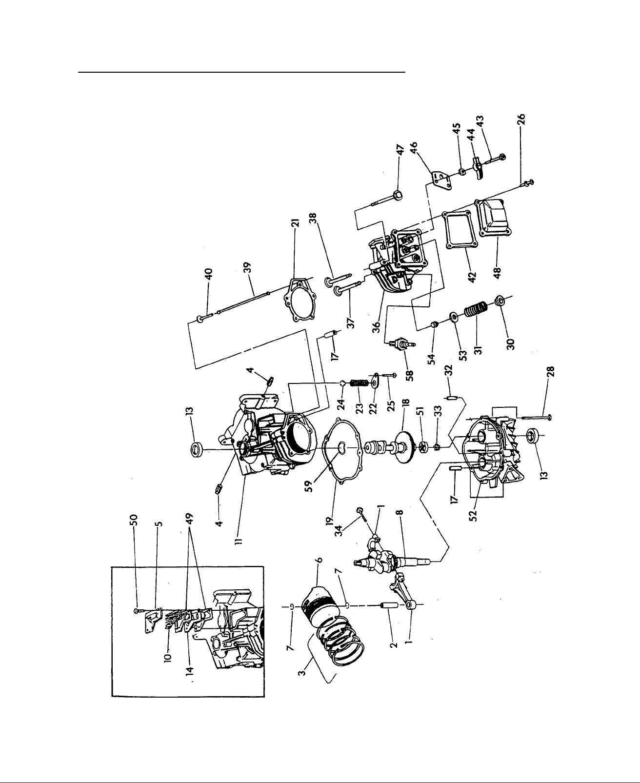
EXPLODED VIEW — ENGINE LONG BLOCK
Drawing No. A6202 Rev. B DATE: AUG. io, 1998
_________________
— 38 —
Page 41

I
______________ _
Drawing No. A6202 Rev. B date: aug. io, 1998
ITEM
1
2 76389
3
4
5
6
7 76390 2
8
10 89923 1
11 89213L 1 ASSEMBLY, CRANKCASE
13
14
17
18
19
21
22 78691
23
24 A5776
25
26 78606 4 SCREW & LOCK WASHER, M6-1 x 12 LONG
28
30
31 88401 2
32 88590 1 DOWEL PIN, DIA. 12 x 18 LONG
33
34 76381 2
36
37
38 90081 1
39 88396A 2 PUSH ROD
40 83235 2
42
43 77161 2 STUD, BALL PIVOT
44 77160
45
46 88403
47 77168
48 88413B 1 COVER, ROCKER
49 78629 2
50 90388 2 BOLT, TAPTITE-M6 X 12 LONG
5J
52
53 84186 2 WASHER, WEAR-VALVE SPRING
54 88156 1
58 72347
59 99922
PART NO.
76380
88411 1 SET. PISTON RING (STD. SIZE)
72657
77176
88057 1 PISTON, 75 DIA.
21860 1 ASSEMBLY, CRANKSHAFT AND GEAR
81695
90604
78699B
A2477
89096 1
A8822 1 GASKET. CYLINDER HEAD
A5772
74908
89230
A1720
83152
21705B 1
90082
96362
76307
83153 1
92977
QTY. DESCRIPTION
REPAIR PARTS — ENGINE LONG BLOCK
1
1 PISTON PIN
2
1 COVER. BREATHER
2
1
3 SLEEVE. DOWEL 0 12
1 ASSEMBLY. CAMSHAFT
1 RETAINER, OIL PRESSURE SPRING
1
1
1
6
2
1 GEROTOR, INNER
1 VALVE. EXHAUST
1 GASKET, ROCKER COVER
2 ROCKER ARM
2 NUT, ROCKER ARM
1
5
1 ASSEMBLY-SUMP, OIL
1 SPARK PLUG, CHAMPION RC12YC
1 WASHER, SPRING
ASSEMBLY, CONNECTING ROD & CAP
PIPE PLUG-1/4 NPT
RETAINER, PISTON PIN
SEPARATOR, OIL BREATHER
SEAL, OIL-CRANKSHAFT
CUP, BREATHER BAFFLE
GASKET, CRANK CASE FLANGE
SPRING, OIL PRESSURE
BALL, OIL PRESSURE
TAPTITE, M5-0.8 X 10
HHFC, M8-1.25X35LONG
RETAINER, VALVE SPRING
SPRING, VALVE
BOLT, CONNECTING ROD
ASSEMBLY, CYLINDER HEAD W/GUIDES & SEATS
VALVE, INTAKE
TAPPET
PLATE, PUSH ROD GUIDE
HEADBOLT, M8 x 52MM
GASKET, BREATHER
GEROTOR. OUTER
SEAL VALVE-INTAKE
39 —
Page 42

ш
€
(Q
>
СО
Í».
о
33
ф
<
m
X
"Ö
о
а
m
о
m
ё
I
о
о
-(>■
о
и
о
Г“
Z
m
Page 43

Drawing No. A9404 Rev. *
REPAIR PARTS — CONTROL PANEL
ITEM PART NO. QTY. DESCRIPTION
1 91526 8
2 20093
20092 ■ 1 BOX, CONTROL PANEL
3
4 36937 2 #10-32x1" PHILLIPS PAN
75476 5 PHILLIPS PAN HD. MACH.
5
74908 8
6
23484M 1 SNAP BUSHING
7
20107
8
92234 1
9
10
13
14
18 22985
19
20 20091
21 30809
22
23 92113
24 A9611
25
26 80939 1
27 65795
28
29 22158
30 20105B
31 86275
32 A3369
33
90145
49226 10
51715
23897
87798 1
32300
22264 16 LOCK WASHER M4 55 22159
43181 4
M50.8X12MM PHILLIPS 34 43182
PAN HD. MACH. SCR. 35
1 BOX. CONTROL TOP 36
HD. MACH. SCR. 38
SCR., M4x 16
TAPTITE M5.8 X 10 LONG 43
1
90 DEG. CONNECTOR
RV CONTROL BOARD HARNESS
CIRCUIT BREAKER30A. 46 91269A 1 REMOTE PANEL HARNESS
1
LOCK WASHER M5
HEX NUT M4 48
2
4 M4 FLAT WASHER
M5 FLAT WASHER
8
CONTROL PANEL. FRONT
1
1 RUBBER GROMMET
SWITCH, SPOT ROCKER 50 25105 2 #632x1/4" PHILLIPS RND.
1 SWITCH, SPSTMOM
ROCKER 51
1 FUSE, 7.5A. AGC
1
1
1 PANEL DECAL 57 36933 2 PPHMS 10-32x3/8" LONG
1 GENISTOR, TRIAC 58
1 ASSEMBLY, PCB CCG
FUSE HOLDER
EXTRUSION, CONTROLLER 53
RECTIFIER, ВАТТ CHARGE
#1032 HEX NUT 56
2
MODULE WASHER, EXTERNAL
TAPTITE, M30.5X10MM 59 29333A 2 BLACK TIE WRAP, 7" LONG
PAN HD. MACH. SCR.
ITEM PART NO. QTY. . DESCRIPTION
4
LOCK WASHERM3
89744 1 RESISTOR, POWER 1 OHM
83491 1 RESISTOR, POWER 500
OHM
37 45756
86722 1
41 7521OA 1 TERMINAL BLOCK
42 91281
86738A 1 TRIAC MODULE HARNESS
44
45
47 23484D 1 SNAP BUSHING
49
52 51718 4 M40.7X10MMHEX HEAD
54 34028 2 #440 X 3/8" LG. ROUND HD.
60 23762 2 SHAKEPROOF EXT. #10
00191297
91282 1 CUSTOMER WIRE
82121A
20106
84867 4 RUBBER UCHANNEL
77604 1
27771
23762 1 SHAKEPROOF LOCK
4
TAPTITE M61 X 10 LONG
BRACKET, HEAT SINKPCB
1
12 PIN CONNECTOR ASSY.
1 GROUND WIRE
2 CLAMP, CONTROL PANEL
HARNESS
1 HARNESS, CONT. PANEL
(NOT SHOWN FOR
CLARITY)
HD. MACH. SCREW
CAPSCREW
HOUR METER
2 #4 LOCKWASHER
2 #440 HEX NUT
TOOTH #10
— 41 —
Page 44

EXPLODED VIEW — ENGINE SHEET METAL
Drawing No. A9194 Rev A
— 42 —
Page 45

_______________
Drawing No. A9194 Rev. A
REPAIR PARTS — ENGINE SHEET METAL
ITEM PART NO. QTY. DESCRIPTION
1
86705
2 49813 2
3 86718 3.5 FT.
4
A3666 1
5 74908 33
A3667 2
6
7 22129 12
8 39414 4
12 89680 1
13
17 89471 1
18 86731A 1
19
20 86726 1
21 86671 1
22 86727 1
23 86719 1
24 20519
25 90141A 1
26 86724 1
27
28 28740 1
29 22127 3
30 22097 7
31
32
33
34 90537 1
35
36 30340 1
37
38 23484D 1
39 23762 2
40 22471 2
41 22264 2
42 79246 2
94670
86715
90475
86729
90518
89048
22145
48031C 5
1
1
1
1
1
1
1
1
4
PLATE, DIVIDER
M6-1.0 HEX NUT
SEAL RUBBER EXTRUSION
WRAPPER, BOX
TAPTITE, M5-.8 X 10MM LG.
MOUNTING BRACKET
M8 LOCK WASHER
M8-1.25 X 35MMHEX HD.
CAPSCREW
SPARK ARRESTOR
CLAMP, EXHAUST
DEFLECTOR, AIR OUT
ASSEMBLY, MUFFLER
HOUSING, LOWER FAN
SKIRT, CARS. BAFFLE
COVER, ROCKER COVER
SKIRT, SPARK PLUG SIDE
PAN, BELLY
FRAME
GROUND STRAP
PLATE, BASE COVER
PUMP, FUEL
BARBED 90 1/8” X 1/4"
HEX NUT, 1/4"-20
LOCK WASHER-1/4”/M6
CONTACTOR, STARTER
BOOT, CONTACTOR
SEAL, OIL FILTER HOLE
RETAINER, SEAL
M8 FLAT WASHER
1/4” FUEL LINE - 4” LONG
1/4" HOSE CLAMP
SNAP BUSHING
EXTERNAL SHAKEPROOF
#8 HEX NUT
#8 LOCK WASHER
H.H.CPSCR., M6-1.0X16MM
W/LOCKWASHER
ITEM PART NO. QTY.
44
45 103-74260 1 GROUND STRAP, UNIT
47
48 92000
49
50
51 86311 1
53 007-91297 1
54 89045 1
57 A3638 1
59 56893 11
60
61 A3764 2
62 66443B 4 VIBRATION MOUNT
63
64 45771
65
67
68 A7213 2 TAG, REMOVE BOLT
69 23897 4 FLAT WASHER #10/M5
70 A9172
71 89047 2
72 86711 1
73 89049B 1 ASSY., IGNITION COIL
74 49721
75
76 91526 2 M5-0.8X 12MM PPHMS
77
78 49226 2
79 84867 .25 FT.
80
81 A9196 1
22447
39450 1
30340
82580D 1
A5767 1
20668
38353 3 VIBRATION MOUNT
79119 2 TAPTITE 1/4”-20 X 1-1/4”
49813
51716 2
56892 1
3 WASHER, INT. SHAKEPROOF,
1
1
2
8
1
2 M6-1.0X35MM H.H. CAPSCR.
4
DESCRIPTION
1/4”/M6
1/8” X 3/16” NPT 90° BARBED
FITTING
BRCKT., MUFFLER HANGER
1/4” FUEL LINE (8” LONG)
3/16” CARB. LINE (4” LONG)
FUEL FILTER
STARTER CONTACTOR
GROUND WIRE
SEAL, WASHER EXH. PIPE
PANEL, WRAPPER BOX
CRIMPTITE, #10-24X1/2”
HEX HD. CAPSCREW,
M5-0.8 X 6MM
CUSTOMER MNTG. BRCKT.
EARTHING STRAP
HEXNUT-M8
BRACKET, IGNITION SYS.
SPACER, IGNITION COIL
MODULE, IGNITION
M6-1.0HEXNUT
M5-0.8 HEX NUT
LOCK WASHER, M5
RUBBER “U" CHANNEL
CRIMPTITE #10-24X3/8”
COVER, IGNITION SYSTEM
-43-
Page 46

CALIFORNIA EMISSION CONTROL WARRANTY STATEMENT
YOUR WARRANTY RIGHTS AND OBLIGATIONS
The California Air Resources Board ('CARB") and Generac Power Systems Inc. are pleased to explain the Emission Control
System Warranty on your new recreational vehicle equipment engine. In California, new utility and lawn and garden equip
ment engines must be designed, built and equipped to meet the State's stringent anti-smog standards. Generac Power
Systems Inc. will warrant the emission control system on your recreational vehicle equipment for the periods of time listed
below provided there has been no abuse, neglect, unapproved modification, or improper maintenance of your recreational
vehicle equipment engine.
Your emission control system may include parts such as the carburetor, ignition system and exhaust system. Also included
may be the compression release system and other emission-related assemblies.
Where a warrantable condition exists, Generac Power Systems Inc. will repair your recreational vehicle equipment engine at
no cost to you for diagnosis, parts and labor.
MANUFACTURER'S EMISSION CONTROL SYSTEM WARRANTY COVERAGE:
Emissions control systems on 1995 and later model year utility and lawn and garden equipment engines are warranted for
two years as hereinafter noted. If, during such warranty period, any emission-related part on your engine is defective in
materials or workmanship, the part will be repaired or replaced by Generac Power Systems Inc..
OWNER'S WARRANTY RESPONSIBILITIES:
As the recreational vehicle equipment engine owner, you are responsible for the performance of the required maintenance
listed in your owners manual. Generac Power Systems Inc. recommends that you retain all receipts covering maintenance on
your recreational vehicle equipment engine, but Generac Power Systems Inc. will not deny warranty solely due to the lack of
receipts or for your failure to provide written evidence of the performance of all scheduled maintenance.
As the recreational vehicle equipment engine owner, you should, however, be aware that Generac Power Systems Inc. may
deny you warranty coverage if your recreational vehicle equipment engine or a part thereof has failed due to abuse, neglect
, improper maintenance or unapproved modifications.
You are responsible for presenting your recreational vehicle equipment engine to a Generac Power Systems Inc. Authorized
Service Outlet as soon as a problem exists. The warranty repairs should be completed in a reasonable amount of time, not to
exceed 30 days.
Warranty service can be arranged by contacting either a Generac Power Systems Inc. Authorized Service Outlet or by con
tacting Generac Power Systems Inc. at:
GENERAC POWER SYSTEMS INC. PH: (414) 473-5514
P.0.B0X8 FX: (414) 472-6505
WAUKESHA, Wl 53187
IMPORTANT NOTE: This warranty statement explains your rights and obligations under the Emission Control System
Warranty ("ECS Warranty") which is provided to you by Generac Power Systems Inc. pursuant to California law. See also the
Generac Power Systems Inc. Limited Warranties for Generac Power Systems Inc. which is enclosed herewith on a separate
sheet and also is provided to you by Generac Power Systems Inc.. The ECS Warranty applies only to the emission control sys
tem of your new engine. To the extent that there is any conflict in terms between the ECS Warranty and the Generac Power
Systems Inc. Warranty, the ECS Warranty shall apply except in any circumstances in which the Generac Power Systems Inc.
Warranty may provide a longer warranty period. Both the ECS Warranty and the Generac Power Systems Inc. Warranty
describe important rights and obligations with respect to your new engine.
Warranty service can only be performed by a Generac Power Systems Inc. Authorized Service Outlet. At the time of request
ing warranty service, evidence must be presented of the date of the sale to the original purchaser. The purchaser shall pay
any charges for making service calls and/or for transporting the produrts to and from the place where the inspection and/or
warranty work is performed. The purchaser shall be responsible for any damage or loss incurred in connection with the
transportation of any engine or any part(s) thereof submitted for inspection and/or warranty work.
Page 47

EMISSION CONTROL SYSTEM WARRANTY
Emission Control System Warranty (“ECS Warranty") for 1995 and Later Model Year Utility and Lawn and Garden Equipment
Engines:
^.Applicability: This warranty shall apply to 1995 and later model year utility and lawn and garden equipment engines. The
ECS Warranty Period (“ECS Warranty Period“) shall begin on the date the new engine or equipment is delivered to its origi
nal, end-use purchaser and shall continue for 24 consecutive months thereafter.
i. General Emissions Warranty Coverage: Generac Power Systems Inc. warrants to the original, end-use purchaser of the new
engine or equipment and to each subsequent purchaser that each of its utility and lawn and garden equipment engines is:
1. Designed, built and equipped so as to conform with all applicable regulations adopted by the Air Resources Board pur
suant to its authority, and
2. Free from defects in materials and workmanship which, at any time during the ECS Warranty Period, will cause a warrant
ed emissions - related part to fail to be identical in all material respects to the part as described in the engine manufac
turer's application for certification.
Z.The ECS Warranty only pertains to emissions-related parts on your engine, as follows:
1. Any warranted, emissions-related parts which are not scheduled for replacement as required maintenance in the Owner's
Manual shall be warranted for the ECS Warranty Period. If any such part fails during the ECS Warranty Period, it shall be
repaired or replaced by Generac Power Systems Inc. according to Subsection (4) below. Any such part repaired or replaced
under the ECS Warranty shall be warranted for any remainder of the ECS Warranty Period.
2. Any warranted, emissions-related part which is scheduled only for regular inspection as specified in the Owner's Manual
shall be warranted for the ECS Warranty Period. A statement in such written instructions to the effect of “repair or
replace as necessary" shall pot reduce the ECS Warranty Period. Any such part repaired or replaced under the ECS
Warranty shall be warranted for any remainder of the ECS Warranty Period.
3. Any warranted, emissions-related part which is scheduled for replacement as required maintenance in the Owner's Manual
shall be warranted for the period of time prior to first scheduled replacement point for that part. If the part fails prior to
the first scheduled replacement, the part shall be repaired or replaced by Generac Power Systems Inc. according to
Subsection (4) below. Any such emissions-related part repaired or replaced under the ECS Warranty shall be warranted for
the remainder of the ECS Warranty Period prior to the first scheduled replacement point for such emissions-related part.
4. Repair or Replacement of any warranted, emissions-related part under this ECS Warranty shall be performed at no charge
to the owner at a Generac Power Systems Inc. Authorized Service Outlet.
5. The owner shall not be charged for diagnostic labor which leads to the determination that a part covered by the ECS
Warranty is in fact defective, provided that such diagnostic work is performed at a Generac Power Systems Inc.
Authorized Service Outlet.
6. Generac Power Systems Inc. shall be liable for damages to other original engine components or approved modifications
proximately caused by a failure under warranty of any emission-related part covered by the ECS Warranty.
7. Throughout the ECS Warranty Period, Generac shall maintain a supply of warranted emission-related parts sufficient to
meet the expected demand for such emission-related parts.
8. Any Generac Power Systems Inc. authorized and approved emission-related replacement part may be used in the perfor
mance of any ECS warranty maintenance or repairs and will be provided without charge to the owner. Such use shall not
reduce Generac Power Systems Inc. ECS warranty obligations.
9. Unapproved add-on modified parts may not be used to modify or repair a Generac Power Systems Inc. engine. Such use
voids this ECS Warranty and shall be sufficient grounds for disallowing an ECS Warranty claim. Generac Power Systems
Inc. shall not be liable hereunder for failures of any warranted parts of a Generac Power Systems Inc. engine caused by
the use of such an unapproved add-on or modified part.
EMISSION RELATED PARTS INCLUDE THE FOLLOWING:
1. Carburetor assembly and its internal components.
a. Fuel filter
b. Carburetor gaskets
c. Fuel pump (if so equipped)
2. Air cleaner assembly
a. Air filter element
b. Intake pipe/manifold
3. Ignition system including:
a. Spark plug
b. Ignition module
4. Catalytic muffler (if so equipped)
a. Muffler gasket (if so equipped)
b. Exhaust manifold (if so equipped)
5. Crankcase breather assembly and its components,
a. Breather connection tube
Page 48

Generac’s Three-Year Limited Warranty For Recreational Vehicle Generators
Generac warrants to the original owner and subsequent purchasers from the date of purchase by the original owner, that its generators will be free
from defects in materials or workmanship tor the period as set forth below. During said warranty period, Generac will, at its option, repair or replace
any part which, upon examination by Generac or a Generac Authorized Distributor and/or Dealer thereof, Is found to be defective from normal use
and service.
This warranty is only effective, upon Generac’s receipt from the original owner, a completed Warranty Registration Card, prior to the expiration of the
warranty period. This card is the only valid registration identification and must be presented at time of requesting Warranty service. Claims will not
be accepted without presentation of this Registration Card.
THREE YEAR WARRANTY SCHEDULE
1. All generators used in a recreational vehicles shall be warranted for a period of three (3) years or 2,000 hours of operation, whichever occurs
first. All parts, labor, removal and reinstallation shall be covered for the first two years. Parts and labor on selected generator and engine parts
shall be covered during the third year or 2,000 hours, whichever occurs first. These selected parts are limited to: the main Rotor and Stator,
Computer Control board (if applicable) with regard to the generator; the Cylinder Block, Cylinder Head, Crankshaft, Piston, Valve, Valve Lifter,
and Manifolds with regard to the engine.
2. The drive belt and pulleys (if so equipped) on air-cooled generator used in recreational vehicles shall be warranted against failure due to defec
tive materials or normal usage for the life of the generator. For the original owner, this drive belt and pulley warranty shall include parts and
labor plus $50.00 payment upon return of the failed belt or pulley by the original owner. For succeeding owners, this drive belt warranty shall
cover belt or pulley parts only.
3. Rental units, demonstrators, prime power, or commercial applications, such as construction or utility, are warranted for (1) one year or 2,000
hours, whichever comes first.
4. This transferable warranty is in effect for all Recreational Vehicle Generators purchased after Jan. 1,1998.
THIS WARRANTY DOES NOT COVER;
Costs of maintenance, installation, and start-up.
Failures due to (a) normal wear and tear from GN engine, or (b) accident, misuse, abuse, negligence or improper installation.
Products which are modified or altered in a manner not authorized by Generac in writing.
/Vny incidental, consequential or indirect damages caused by defects in materials or workmanship, or any delay in repair or replacement of
defective parts.
Failure due to misapplication.
Telephone, telegraph, teletype or other communication expense.
Living or travel expenses of persons performing service.
Any and all transportation/travel expenses.
Rental equipment used while warranty repairs are being performed.
Overtime labor.
Starting batteries, fuses, light bulbs, and engine fluids.
**NORMAL WEAR: As with all mechanical devices, the GN-Series engines need periodic parts service and repiacement to perform weil.
This warranty wili not cover repair when normal use has exhausted the life of a part or an engine.
There is no other express warranty. Generac hereby disclaims any and all implied warranties, including but not limited to those of merchantability
and fitness for a particular purpose to the extent permitted by law. The duration of any implied warranties which cannot be disclaimed is limited to
the time period (one year) as specified in the express warranty. Liability for consequential, incidental or special damages under any and all war
ranties is excluded to the extent permitted by law. Some states do not allow limitations on how long an implied warranty lasts, or the exclusion or
limitation of incidental or consequential damages, so the above limitations or exclusions may not apply to you. This warranty gives you specific legal
rights and you may also have other rights, which vary from state to state.
For service, see your nearest GENEFtAC authorized warranty service facility or call 1-800-526-2871. Warranty service can be performed only by a
GENERAC authorized service facility. This warranty will not apply to service at any other facility. At the time of requesting warranty service, evidence
of original purchase date must be presented.
Generac Power Systems Inc.
P.O. Box 8 Waukesha, Wl 53187 Telephone: (414) 473-5514 Fax; (414) 472-6505
 Loading...