

Page 1

Instruction Manual
Wireless Local Monitor
Model: 006664-0
NOTE:
This display unit and it's generator transceiver are a matched pair. The included
display unit will only function with the included generator transceiver.
www.generac.com or 1-888-GENERAC
Page 2

Table of Contents
TABLE OF CONTENTS
SAFETY ..........................................................................................................................1
Read This Manual Thoroughly ................................................................................... 2
Safety Rules ............................................................................................................... 3
Operation and Maintenance ....................................................................................... 4
How to Obtain Service ................................................................................................ 5
INTRODUCTION ............................................................................................................. 5
Generator Compatibility .............................................................................................. 6
INSTALLATION ...............................................................................................................6
Transceiver Installation ...............................................................................................6
Generator Side Transceiver Installation Instructions - Air-cooled Generators ..... 6
Display Unit Installation ............................................................................................ 10
Battery Installation .............................................................................................. 10
Signal Strength Test ........................................................................................... 10
Signal Strength Test Quick Reference Chart ..................................................... 11
Display Unit Mounting ........................................................................................11
OPERATION ................................................................................................................. 12
Wireless Local Monitor General Operation .............................................................. 12
Generator Transceiver Status Light ................................................................... 12
Display Unit Green Light (Generator OK or Running)........................................ 12
Display Unit Yellow Light (Maintenance Needed or Warning Active) ................ 12
Display Unit Red Light (Check Generator Status, Call Dealer if Necessary) ....13
Low Battery Indicator .......................................................................................... 13
TROUBLESHOOTING ..................................................................................................14
QUICK REFERENCE CHART ......................................................................................15
NOTES ..........................................................................................................................16
WARRANTY .................................................................................................................. 17
CALIFORNIA PROPOSITION 65 WARNING
This product contains or emits chemicals known to the State of California
to cause cancer, birth defects and other reproductive harm.
Page 3

Safety
SAFETY
Contains FCC ID: OA3MRF89XAM9A
This device complies with Part 15 of the FCC Rules.
Operation is subject to the following two conditions:
1. This device may not cause harmful interference, and
2. This device must accept any interference received, including interference that may cause
undesired operation.
This equipment has been tested and found to comply with the limits for a Class B digital
device, pursuant to Part 15 of the FCC rules. These limits are designed to provide reasonable
protection against harmful interference in a residential installation. This equipment generates,
uses and can radiate radio frequency energy and if not installed and used in accordance with
the instructions, may cause harmful interference to radio communications. However, there
is no guarantee that interference will not occur in a particular installation. If this equipment
does cause harmful interference to radio or television reception, which can be determined by
turning the equipment OFF and ON, the user is encouraged to try to correct the interference
by one or more of the following measures:
• Reorient or relocate the receiving antenna.
• Increase the separation between the equipment and receiver.
• Connect the equipment into an outlet on a circuit different from that to which the receiver
is connected.
• Consult the dealer or an experienced radio/TV technician for help.
Section 7.1.3 of RSS-GEN
This device complies with Industry Canada license exempt RSS standard(s). Operation is
subject to the following two conditions:
1. This device may not cause interference, and
2. This device must accept any interference, including interference that may cause
undesired operation of the device.
T o satisfy with FCC RF exposure requirements for mobile and base station transmission devices,
a separation distance of 20 cm or more should be maintained between the antenna of this device
and persons during operation. To ensure compliance, operation at closer than this distance is
not recommended. The antenna(s) used for this transmitter must not be co-located or operating
in conjunction with any other antenna or transmitter.
1
Page 4

Safety Rules
S AVE THESE INSTRUCTIONS – This manual is in addition to the
Owner's Manual for the generator. All warnings and recommendations
in the manufacturer's manuals must be strictly adhered to for safe
use.
S AVE THESE INSTRUCTIONS – The manufacturer suggests that these
rules for safe operation be copied and posted in potential hazard
areas. Safety should be stressed to all operators, potential operators,
and service and repair technicians for this equipment.
S AVE THESE INSTRUCTIONS – This manual contains important
instructions that should be followed during installation and
maintenance of the generator and batteries.
READ THIS MANUAL THOROUGHLY
If any portion of this manual is not understood, contact the nearest Authorized Service Dealer for
starting, operating and servicing procedures.
Throughout this publication, and on tags and decals affixed to the generator, DANGER, WARNING,
CAUTION and NOTE blocks are used to alert personnel to special instructions about a particular
service or operation that may be hazardous if performed incorrectly or carelessly. Observe them
carefully. Their definitions are as follows:
INDICATES A HAZARDOUS SITUATION OR ACTION WHICH, IF NOT AVOIDED, WILL
RESULT IN DEATH OR SERIOUS INJURY.
Indicates a hazardous situation or action which, if not avoided, could
result in death or serious injury.
Indicates a hazardous situation or action which, if not avoided, could
result in minor or moderate injury.
NOTE:
Notes contain additional information important to a procedure and will be found within the
regular text body of this manual.
These safety warnings cannot eliminate the hazards that they indicate. Common sense and strict
compliance with the special instructions while performing the action or service are essential to
preventing accidents.
2
Page 5

Safety Rules
Four commonly used safety symbols accompany the DANGER, WARNING and CAUTION
blocks. The type of information each indicates is as follows:
This symbol points out important safety information that, if not
followed, could endanger personal safety and/or property of others.
This symbol points out potential explosion hazard.
This symbol points out potential fire hazard.
This symbol points out potential electrical shock hazard.
SAFETY RULES
Study these SAFETY RULES carefully before installing, operating or servicing this equipment.
Become familiar with this Owner’s Manual and with the unit. The generator can operate safely,
efficiently and reliably only if it is properly installed, operated and maintained. Many accidents are
caused by failing to follow simple and fundamental rules or precautions.
The manufacturer cannot anticipate every possible circumstance that might involve a hazard. The
warnings in this manual, and on tags and decals affixed to the unit are, therefore, not all-inclusive.
If using a procedure, work method or operating technique the manufacturer does not specifically
recommend, ensure that it is safe for others. Also make sure the procedure, work method or
operating technique utilized does not render the generator unsafe.
Despite the safe design of this unit, operating this equipment
imprudently, neglecting its maintenance or being careless can cause
possible injury or death. Permit only responsible and capable persons
to operate or maintain this equipment.
Potentially lethal voltages are generated by these machines. Ensure
all steps are taken to render the machine safe before attempting to
work on the generator.
Parts of the generator are rotating and/or hot during operation.
Exercise care near running generators.
3
Page 6

Safety Rules
GENERAL HAZARDS
• For safety reasons, the manufacturer recommends that the installation, initial start-up and
maintenance of this equipment is carried out by a Dealer.
• Keep hands, feet, clothing, etc., away from drive belts, fans, and other moving or hot parts.
Never remove any drive belt or fan guard while the unit is operating.
• When working on this equipment, remain alert at all times. Never work on the equipment when
physically or mentally fatigued.
ELECTRICAL HAZARDS
• Do not handle any kind of electrical device while standing in water, while barefoot, or while
hands or feet are wet. DANGEROUS ELECTRICAL SHOCK MAY RESULT.
• In case of accident caused by electric shock, immediately shut down the source of electrical
power. If this is not possible, attempt to free the victim from the live conductor. AVOID DIRECT
CONTACT WITH THE VICTIM. Use a nonconducting implement, such as a dry rope or board,
to free the victim from the live conductor. If the victim is unconscious, apply first aid and get
immediate medical help.
• Never wear jewelry when working on this equipment. Jewelry can conduct electricity resulting in
electric shock, or may get caught in moving components causing injury.
EXPLOSION HAZARDS
• Do not smoke around the generator. Wipe up any fuel or oil spills immediately. Ensure that no
combustible materials are left in the generator compartment, or on or near the generator, as
FIRE or EXPLOSION may result. Keep the area surrounding the generator clean and free from
debris.
OPERA TION AND MAINTENANCE
The operator is responsible for proper and safe use of the equipment. The manufacturer strongly
recommends that the operator read this Owner's Manual and thoroughly understand all instructions
before using this equipment. The manufacturer also strongly recommends instructing other users
to properly start and operate the unit. This prepares them if they need to operate the equipment in
an emergency.
It is the operator's responsibility to perform all safety checks, to make sure that all maintenance
for safe operation is performed promptly, and to have the equipment checked periodically by
an Authorized Service Dealer. Normal maintenance service and replacement of parts are the
responsibility of the owner/operator and, as such, are not considered defects in materials or
workmanship within the terms of the warranty. Individual operating habits and usage contribute to
the need for maintenance service.
Operating instructions presented in this manual assume that the standby electric system has been
installed by an Authorized Service Dealer or other competent, qualified contractor. Installation of
this equipment is not a “do-it-yourself” project.
4
Page 7

Introduction
HOW TO OBTAIN SERVICE
When the generator requires servicing or repairs, contact an Authorized Service Dealer for
assistance. Service technicians are factory-trained and are capable of handling all service needs
(1-800-333-1322).
When contacting an Authorized Service Dealer about parts and service, always supply the
complete model number of the unit as given on the front cover of this manual or on the DATA
LABEL affixed to the unit.
INTRODUCTION
The Wireless Local Monitor consists of one transceiver, mounted on the generator, and a display
unit, placed in a convenient viewing location within the home or business. The system has a “line of
sight” range of about 600 feet, but this will be reduced when the signal has to pass through walls,
floors, etc., of a typical installation. With this remote monitoring system, the status of the generator
can be checked easily from within the home or business.
The generator transceiver and display unit are shipped from the factory paired. These units are prepaired to ensure communication and prevent cross-communication from other devices in the area.
NOTE:
Some building materials may completely block the passage of the signal, for example,
steel beams, metal siding and foil radiant barrier insulation.
• The Wireless Local Monitor indicates the generator status via three lights - Green, Yellow or
Red.
• The Test button performs a Signal Strength Test.
• The Battery Status Indicator provides low battery status.
• The Buzzer gives an audible warnings in conjunction with Yellow or Red lights.
TEST BUTTON
BUZZER - sounds with
YELLOW or RED LIGHTS
BATTERY STATUS INDICATOR
RED LIGHT - Alarm / generator shuts down
YELLOW LIGHT - Warning or Maintenance
GREEN LIGHT - Generator OK / generator operates
required / generator operates
Wireless Local Monitor Functions
5
Page 8

Installation
GENERATOR COMPATIBILITY
• This unit can be installed on all 2008 and later air-cooled home standby units with an LCD
display and all 2010 and later liquid-cooled gaseous fuel standby units. The unit can also be
used on 2013 and later Evolution controlled liquid-cooled diesel fuel standby units.
• Certain liquid-cooled units require the use of adapter harness (model 006665-0). These units
are as follows:
- All Protector Series and QT generators that do not have a pre-stamped mounting location.
- Units larger than 60kW.
Note: The adapter harness is recommended, but not required on units 60kW and below.
• Maximum ambient temperature rating: 122 °F / 50 °C.
TRANSCEIVER INSTALLATION
GENERATOR SIDE TRANSCEIVER INSTALLATION INSTRUCTIONS - AIR-COOLED
GENERATORS
The following steps illustrate how to mount the generator side transceiver to an air-cooled generator.
For liquid-cooled generator applications, an adaptor kit is required and comes with additional
instructions.
NOTE:
The generator battery will be disconnected and reconnected during the installation
process which may result in an “Inspect Battery” warning being displayed on the
generator controller. This is normal and is no cause for concern; simply clear the warning
from the generator controller following the operating instructions for the generator
controller. The time and date will also need to be reset once the starting battery is
reconnected.
1. Remove the T1 fuse from the transfer switch.
2. Unlock both locks and open the top lid of the generator.
3. Set the generator to the OFF mode.
4. Remove the 7.5 Amp control panel fuse.
5. Remove the front access panel from the enclosure.
6. Disconnect the negative (-) black battery cable. Then, disconnect the positive red (+) cable.
7. If applicable, turn OFF the main breaker in your home's utility breaker electrical panel. This is
necessary if installation is being performed after the generator has been connected to utility
power.
NOTE:
There are different controller configurations for various model years. Follow the next steps
related to your generator depending on the model year.
6
Page 9

Installation
Transceiver Installation - 2008 - 2012 with LCD Display
1. Locate the mounting feature and cover plate on the back of the generator. Remove the
cover plate, then position transceiver on the back of the generator ensuring the gasket
provides sealing.
MOUNTING LOCATION
Transceiver Mounting Location
2. Install 2 screws from inside the generator to secure the transceiver to the generator wall.
Transceiver Status
Light location
Transceiver Mounting Fasteners,
Transceiver Status Light Location and Wiring Connector
7
Page 10

Installation
Transceiver Installation - 2013 and Later
NOTE:
Some 2013 units do not have the transceiver mounting holes. The template (provided)
must be used.
1. Affix the template, on the back of the generator enclosure, in the upper left corner. Align the
template with the left and top edges of the enclosure. Tape the template in place and mark the
enclosure, in preparation to drill the hole locations.
2. Inspect the area behind the template to ensure there is adequate clearance when drilling.
Move all wires to prevent damage.
3. Using the template, drill the harness opening and mounting holes.
4. Position transceiver on the back of the generator ensuring the gasket provides sealing.
5. Install transceiver to generator wall using 2 screws to secure the unit.
Wiring Procedure - All Years
1. Connect the 4-pin connector to the transceiver.
2. On 2008 Home Standby Units only, remove the fasteners that secure the controller and lift the
controller to access the accessory port.
4. If there is a decal labeled "Port 1", remove decal to locate connector. If there is no decal, locate
the open 8-pin connector on the underside of the controller.
5. Route cable to mate with the connector on the bottom of the controller.
6. Install the harness 8-pin connector into the controller's open socket. See controller drawings
to locate the proper location for the wiring loom connector of the open 8-pin connector.
NOTE:
The connector(s) will only fit one way. Do NOT force.
8
2008 Controller
Page 11

2010 Controller
Installation
2013 Controller
9
Page 12

Installation
Final Installation - All Years
1. Reconnect the positive (+) red battery cable first. Then, reconnect the negative (-) black cable.
2. Install the controller and cover. Secure with fasteners (2008 Home Standby Units only).
3. Reinstall the generator front access panel.
4. Install the 7.5 Amp control panel fuse.
5. Reinstall the T1 fuse into the transfer switch.
6. If applicable, turn ON the home's electrical panel main breaker.
7. Place the generator in the AUTO mode.
8. Use install wizard to set the date, time and exercise function.
DISPLAY UNIT INSTALLATION
BATTERY INSTALLATION
The Wireless Local Monitor display unit is powered by two non-rechargeable AAA alkaline batteries
that are installed by removing the battery cover on the back of the unit. Observe correct battery
polarity which is indicated near the battery compartment. The expected battery life under normal
use is six months when using standard AAA 1.5V, 1.2Ah alkaline batteries.
NOTE:
Batteries should be changed when the low battery indicator warning is activated.
The Wireless Local Monitor does not have a power switch. The monitor automatically powers up
when the batteries are inserted.
SIGNAL STRENGTH TEST
The display unit is equipped with a Signal Strength Test Mode. Press the Test button for five (5)
seconds to enter the Signal Strength Test Mode. The Green, Yellow and Red lights will alternately
light for a short period to indicate transition from Status mode to the Signal Strength Test Mode. The
unit will be in this mode for 30 seconds. During the Signal Strength Test:
• Green - Good Signal Strength
• Yellow - Marginal Signal Strength
• Red - No Signal Strength
After 30 seconds, the unit will automatically exit the Signal Strength Test Mode. When this happens,
the indicators alternately light to signal the transition back to Status Mode.
NOTE:
Extended or frequent use of the Signal Strength Test may deplete battery life.
NOTE:
The display unit will still work if the signal strength is yellow but battery life may be
reduced.
10
Page 13

Installation
SIGNAL STRENGTH TEST QUICK REFERENCE CHART
Signal Strength Test is active - Display unit button must be pressed for more than 5 seconds Display unit lights will go from providing current generator status to a rotating light pattern to signal
a change in function to a Signal Strength Test Mode. It will repeat the rotating light pattern when it
exits Signal Strength Test Mode.
Green
Light
ON OFF OFF Strong signal from Transceiver unit to Display unit.
OFF ON OFF Weak signal from Transceiver to Display unit.
OFF OFF ON No signal from Transceiver to Base unit.
Yellow
Light
Red Light Meaning
DISPLAY UNIT MOUNTING
There are three ways to mount the display unit:
• Desk Mount (included)
• Wall Mount
• Magnet Mount (included)
NOTE:
The display unit is intended to be mounted indoors only. Avoid mounting the display unit
in wet or damp locations.
NOTE:
Make sure to perform Signal Strength Test with display unit in intended location. For
example, test with the unit held against the refrigerator or wall to verify signal strength. If
there is low to no signal strength when the unit is held against a surface, the Desk Mount
should be used to ensure communication.
1. Perform Signal Strength Test (refer to Signal Strength Test section of manual) to determine
appropriate home location.
2a. For Desk Mount use, install Desk Mount in holes on back of display unit and place.
2b. For Wall Mount, measure distance between screw mounts on the back of the display unit and
install two screws into wall to hang the unit from.
2c. For Magnet Mount use, remove adhesive from magnet and affix the magnet to the rear of
display unit in the pocket provided.
NOTE:
Installing the magnet will hide the screw holes in the wall mounts so the magnet must be
removed if the screw wall mount method is used.
11
Page 14

Operation
WIRELESS LOCAL MONITOR GENERAL OPERATION
The normal state of the display unit is to have no lights active. This indicates that the
generator has no problems. When any problems occur, the lights will indicate the problem
based on the information in this section.
GENERATOR TRANSCEIVER STATUS LIGHT
The generator transceiver has a green status light that indicates it has power and is communicating
with the display unit. This light can be viewed inside the generator compartment, through the wire
loom opening when the generator lid is raised.
• Solid light Green light - power present / communication established
• Flashing Green light - power present / no communication
DISPLAY UNIT GREEN LIGHT (GENERATOR OK OR RUNNING)
During normal operation, if the generator is in AUTO mode and does not have any maintenance
actions, warnings or alarms active, no lights will be illuminated.
To verify the status of the generator, the Test button can be pressed to show the status. If the
generator is set to AUTO mode and no alarms or warnings are present, the green light will
illuminate when the Test button is pressed.
The green light will flash every five (5) seconds when the generator is running either in AUTO or
MANUAL mode.
DISPLAY UNIT YELLOW LIGHT (MAINTENANCE NEEDED OR WARNING ACTIVE)
The yellow light indicates either:
• Generator warning is present
• Generator maintenance is required.
The generator will not be prevented from running when the yellow light is on.
When active and the generator is not running, the yellow light will flash once every five (5) seconds.
If the generator is running with a yellow light active, both the green and yellow lights will flash once
every five (5) seconds.
The internal buzzer will sound once every four (4) hours for one (1) second when the yellow light
is active. During a period of inactivity, the buzzer may be silenced by briefly pressing and releasing
the Test button; the buzzer will pulse twice to indicate it has been silenced. The buzzer will not
reactivate until a new alarm has been detected.
NOTE:
If the button is pressed while the buzzer is sounding, it may not be silenced.
12
Page 15

Operation
DISPLAY UNIT RED LIGHT (CHECK GENERATOR STATUS, CALL DEALER IF
NECESSARY)
The red light indicates either:
• The AUTO/OFF/MANUAL button on the generator is in the OFF mode
• A generator alarm is present.
If a generator alarm is present, the generator will not start and run in the event of a utility loss or will
be automatically shut down if the engine is already running.
When active, the red light will flash once every five (5) seconds.
The internal buzzer will sound once every hour for five (5) seconds when the Red light is on. During
a period of inactivity, the buzzer can be silenced by briefly pressing and releasing the Test button;
the buzzer will pulse twice to indicate it has been silenced. The buzzer will not reactivate until a new
alarm has been detected.
NOTE:
If the button is pressed while the buzzer is sounding, it may not be silenced.
LOW BATTERY INDICATOR
The battery status indicator will flash every five (5) seconds, and the buzzer will sound every 15
minutes when a low battery is detected. The batteries should be replaced immediately.
Once the batteries are replaced, check the status of the generator by pressing the Test button to
verify operation.
During a period of inactivity, the buzzer can be silenced by briefly pressing and releasing the Test
button; the buzzer will pulse twice to indicate it has been silenced. The buzzer will not reactivate
until a new alarm has been detected.
13
Page 16

Troubleshooting
TROUBLESHOOTING
Problem Possible Causes Possible Corrective Actions
Generator
transceiver light
not illuminated
Generator transceiver light fl ashing
Display unit -yellow
and red lights are
fl ashing
Display Unit – All
lights fl ashing
(communication
lost between
Generator
Transceiver and
Display unit)
Display Unit – No
lights illuminate
when button
pressed
Battery - Battery
life is less than
expected
Low signal strength
The transceiver is not receiving power.
Connection to generator transceiver
may not be made.
The transceiver is not receiving power.
Fuse has failed, been damaged or is
removed from generator controller.
The transceiver is not receiving power.
Generator battery is disconnected.
The transceiver is not in communication with the display unit.
The generator transceiver is not communicating with the generator.
Display unit is out of range with
generator transceiver.
Generator transceiver is not communicating with generator controller or
is not receiving power.
The transceiver is not receiving power.
Fuse has failed, been damaged or is
removed from generator controller.
The transceiver is not receiving power.
Generator battery is disconnected.
Dead batteries. Check and replace batteries.
Low signal strength.
Signal reduced due to travel through
various mediums, such as, metal
siding, tinted or fi ltered windows,
brick, multiple walls or atmospheric
conditions.
Check that the harness transceiver
connection is made properly at the
transceiver and controller.
Check and replace fuse.
Check generator battery connections.
Install or replace batteries.
Display unit may be out of range.
Check the wiring harness and
connections between the Generator
control panel and the transceiver.
Check range status by performing the
Signal Strength Test and move display
unit closer to generator until range is
acceptable.
Check that the connection to the
transceiver is made properly.
Check that the connection to the
controller is made properly.
Check and replace fuse.
Check generator battery connections.
Perform the Signal Strength Test
and relocate to a location with higher
signal strength, if necessary.
Perform the Signal Strength Test
and relocate to a location with higher
signal strength, if necessary.
14
Page 17

QUICK REFERENCE CHART
Quick Reference Chart
Green
Light
———
OFF OFF
Flash
every 5
seconds
OFF
OFF
Flash
every 5
seconds
ON OFF OFF — OFF
Flash
every 3
seconds
Yellow
Light
Flash
every 5
seconds
Flash
every 5
seconds
Flash
every 5
seconds
OFF OFF — OFF Generator running normally.
Flash
every 3
seconds
Red
Battery Status
Light
Flash every 5
Flash
every 5
seconds
OFF —
OFF —
Flash
every 5
seconds
Flash
every 3
seconds
Indicator
seconds
—
— OFF
— OFF
Buzzer Meaning
1 second
every 15
minutes
5 seconds
every hour
1 second
every
4 hours
1 second
every
4 hours
Replace batteries in Display
unit. Remove batteries to
silence buzzer.
Generator will not run. Alarm
condition reported. Press
Test button to silence buzzer.
Buzzer will re-activate with new
warning.
Generator is running with
warning. Press Test button to
silence buzzer. Buzzer will
re-activate with new warning.
Generator is not running, but
will if needed. Generator
warning reported. Press Test
button to silence buzzer.
Buzzer will re-activate with new
warning.
The generator transceiver is
not communicating with the
generator controller.
Generator is standing by, ready
to run. No issues reported.*
Display unit has lost
contact with Transceiver unit.
* Display unit button must be pressed to obtain this status.
15
Page 18

Notes
16
Page 19

Warranty
GENERAC POWER SYSTEMS “ONE YEAR” LIMITED
WARRANTY FOR WIRELESS REMOTE MONITOR
(FOR RESIDENTIAL/COMMERCIAL GENERATORS)
For a period of one (1) year from the date of original sale, Generac Power Systems, Inc.
(Generac) warrants its wireless remote monitor will be free from defects in materials and
workmanship for the items and period set forth below. Generac will, at its discretion, repair
or replace any part that, upon examination, inspection and testing by Generac or a Generac
Authorized Warranty Service Dealer, is found to be defective. Any equipment that the
purchaser/owner claims to be defective must be returned to and examined by the nearest
Generac Authorized Warranty Service Dealer. All transportation costs under the warranty,
including return to the factory, are to be borne and prepaid by the purchaser/owner. This
warranty applies only to the Generac wireless remote monitor and is not transferable from
original purchaser.
The warranty period begins on the date of purchase by the first retail end user, and continues
for the period of time stated above. “Consumer Application” means personal residential
household use by a retail consumer. No other use is warranted.
CONSUMER APPLICA TION
One (1) Year - Limited comprehensive coverage on Parts
THIS WARRANTY SHALL NOT APPLY TO THE FOLLOWING:
1. Any unit manufactured prior to January 1, 2014.
2. Any travel expenses to troubleshoot, remove, replace or adjust a part(s).
3. Normal customer maintenance items.
4. Failures due, but not limited, to the following:
• Storage • Misuse
• Improper installation • Abuse
• Improper repair/diagnosis • Accident
• Improper maintenance • Misapplication
• Normal wear and tear • Negligence
5. Failures caused by any external cause or act of God, such as collision, theft, vandalism,
riot or wars, nuclear holocaust, fire, freezing, lightning, earthquake, windstorm, hail,
volcanic eruption, water or flood, tornado or hurricane.
6. Products and/or part(s) that are modified or altered in a manner not authorized by
Generac in writing.
7. Any incidental, consequential or indirect damages caused by defects in materials or
workmanship, or any delay in repair or replacement of the defective part(s).
8. Failure due to misapplication.
9. Telephone, telegraph, teletype or other communication expenses.
10. Living or travel expenses of person(s) performing service, except as specifically included
within the terms of a specific unit warranty period.
11. Rental equipment used while warranty repairs are being performed.
17
Page 20

Warranty
12. Freight costs for replacement part(s).
13. Labor charges.
THIS WARRANTY IS IN PLACE OF ALL OTHER WARRANTIES, EXPRESSED OR
IMPLIED. SPECIFICALLY, GENERAC MAKES NO OTHER WARRANTIES AS TO THE
MERCHANTABILITY OR FITNESS FOR A PARTICULAR PURPOSE. Any implied warranties
which are allowed by law, shall be limited in duration to the terms of the express warranty
provided herein. Some states do not allow limitations on how long an implied warranty lasts,
so the above limitation may not apply to you. GENERAC’S ONLY LIABILITY SHALL BE THE
REPAIR OR REPLACEMENT OF PART(S) AS STATED ABOVE. IN NO EVENT SHALL
GENERAC BE LIABLE FOR ANY INCIDENTAL OR CONSEQUENTIAL DAMAGES, EVEN IF
SUCH DAMAGES ARE A DIRECT RESULT OF GENERAC’S NEGLIGENCE.
Some states do not allow the exclusion or limitation of incidental or consequential damages,
so the above limitation may not apply to you. This warranty gives you specific legal rights. You
may also have other rights from state to state.
GENERAC POWER SYSTEMS, INC.
S45 W29290 Hwy. 59 • Waukesha, WI 53189
Ph: (888) GENERAC (436-3722) • Fax: (262) 544-4851
To locate the nearest Authorized Dealer visit our website at www.generac.com
Part No. 0K5816 Rev. C (11/13)
PROCEDURE FOR FILING CLAIM:
If you encounter a problem with your remote monitor, please review the installation and programming
sections to ensure that the guidelines were followed.
If a problem still exists, please contact 888-GENERAC (888-436-3722) for assistance and have your
proof of purchase available for verifi cation.
After speaking with a customer service representative, a decision will be made if a replacement
remote monitor will be sent out to you free of charge.
Generac Power Systems recommends that the installation of the remote monitor be performed by a
qualifi ed installer/dealer .
NOTE: Labor and travel charges ARE NOT allowed under this factory warranty.
Manual Part No. 0K5815 Revision C (07/29/14)
Page 21

Manual de instrucciones
Monitor inalámbrico local
Modelo: 006664-0
NOTA:
Esta unidad de pantalla y su transceptor de generador son un par apareado. La unidad de
pantalla incluida solo funcionará con el transceptor de generador incluido.
www.generac.com o 1-888-GENERAC
Page 22

Índice
ÍNDICE
SEGURIDAD .......................................................................................................................... 1
Lea este manual minuciosamente .................................................................................... 2
Reglas de seguridad ......................................................................................................... 3
Funcionamiento y mantenimiento ..................................................................................... 4
Cómo obtener servicio ...................................................................................................... 5
INTRODUCCIÓN .................................................................................................................... 5
Compatibilidad del generador ........................................................................................... 6
INSTALACIÓN ....................................................................................................................... 6
Instalación del transceptor ................................................................................................ 6
Instrucciones de instalación del transceptor en el lado del generador - Generadores
enfriados por aire ........................................................................................................ 6
Instalación de la unidad de pantalla ................................................................................ 10
Instalación de la batería............................................................................................ 10
Prueba de intensidad de la señal ............................................................................. 10
Tabla de referencia rápida para la prueba de intensidad de la señal....................... 11
Montaje de la unidad de pantalla.............................................................................. 11
FUNCIONAMIENTO ............................................................................................................. 12
Funcionamiento general del monitor inalámbrico local ................................................... 12
Luz de estado del transceptor de generador ............................................................ 12
Luz verde de la unidad de pantalla (Generador BIEN o funcionando)..................... 12
Luz amarilla de la unidad de pantalla (Mantenimiento requerido
o advertencia activa) ................................................................................................. 12
Luz roja de la unidad de pantalla (Comprobar el estado del generador,
llamar al concesionario si es necesario) .................................................................. 13
Indicador de carga baja de batería ........................................................................... 13
RESOLUCIÓN DE PROBLEMAS ....................................................................................... 14
TABLA DE REFERENCIA RÁPIDA .................................................................................... 15
NOTAS ................................................................................................................................. 16
Í
GARANT
Este producto contiene o emite sustancias químicas que son conocidas por el Estado de California
A ........................................................................................................................... 17
ADVERTENCIA DE LA PROPOSICIÓN 65 DE CALIFORNIA
como causantes de cáncer, defectos congénitos y otros daños reproductivos.
Page 23

Seguridad
SEGURIDAD
Contiene identificación de la FCC: OA3MRF89XAM9A
Este dispositivo cumple con la Parte 15 de las Reglas de la Comisión Federal de Comunicaciones (FCC)
de EE. UU.
El funcionamiento está sujeto a las siguientes dos condiciones:
1. Este dispositivo no debe causar interferencia perjudicial, y
2. Este dispositivo debe aceptar cualquier interferencia recibida, incluso la interferencia que podría
causar el funcionamiento no deseado.
Este equipo ha sido probado y se determinó que cumple con los límites para un dispositivo digital Clase
B, conforme a la Parte 15 de las Reglas de la FCC de EE. UU. Estos límites están diseñados para
proporcionar protección razonable contra interferencia perjudicial en una instalación residencial. Este
equipo genera, utiliza y puede radiar energía de radiofrecuencia, y, si no se instala y usa con arreglo a
las instrucciones, puede provocar interferencia perjudicial para las radiocomunicaciones. Sin embargo,
no hay ninguna garantía de que no ocurra interferencia en una instalación en particular. Si este equipo
provoca interferencia perjudicial en la recepción de radio o televisión, lo que se puede determinar
encendiendo y apagando el equipo, se alienta al usuario para que intente corregir la interferencia
mediante una de las siguientes medidas:
• Reorientar o reubicar la antena receptora.
• Aumentar la separación entre el equipo y el receptor.
• Conectar el equipo en un tomacorriente de un circuito diferente de aquel en el que está conectado
el receptor.
• Consultar al concesionario o a un técnico de radio/televisión experimentado en busca de ayuda.
Sección 7.1.3 de RSS-GEN
Este dispositivo cumple con la excepción de licencia de la(s) norma(s) RSS de Industry Canada.
El funcionamiento está sujeto a las siguientes dos condiciones:
1. Este dispositivo no debe causar interferencia, y
2. Este dispositivo debe aceptar cualquier interferencia, incluso la interferencia que podría causar
funcionamiento no deseado del dispositivo.
Para satisfacer los requisitos de exposición a la RF de la FCC de EE. UU. para los dispositivos
transmisores de estaciones móviles o fijas, se debe mantener una distancia de separación de 20 cm
o más entre la antena de este dispositivo y las personas durante el funcionamiento. Para asegurar el
cumplimiento, no se recomienda la operación más cerca que esta distancia. La(s) antena(s) usada(s)
para este transmisor no debe(n) compartir el emplazamiento u operar en conjunto con ninguna otra
antena o transmisor.
1
Page 24
Reglas de seguridad
GUARDE ESTAS INSTRUCCIONES - Este manual es un agregado al
Manual del propietario del generador. Observe estrictamente todas las
advertencias y recomendaciones del manual del fabricante para un uso
seguro.
GUARDE ESTAS INSTRUCCIONES - El fabricante sugiere que estas reglas
para funcionamiento seguro sean copiadas y expuestas en zonas de
peligro potencial. Se debe hacer hincapié en la seguridad con todos los
operadores, posibles operadores y técnicos de servicio y reparación de
este equipo.
GUARDE ESTAS INSTRUCCIONES - Este manual contiene instrucciones
importantes que deben ser seguidas durante la instalación y
mantenimiento del generador y las baterías.
LEA ESTE MANUAL MINUCIOSAMENTE
Si una parte de este manual no se comprende, comuníquese con el concesionario de servicio autorizado
más cercano para los procedimientos de arranque, funcionamiento y mantenimiento.
En toda esta publicación, en los rótulos y en las etiquetas adhesivas fijadas en el generador, los bloques
de PELIGRO, ADVERTENCIA, PRECAUCIÓN y NOTA se usan para alertar al personal sobre instrucciones
especiales acerca de un servicio u operación en particular que puede ser peligrosa si se efectúa de manera
incorrecta. Obsérvelos cuidadosamente. Sus definiciones son las siguientes:
¡PELIGRO!
INDICA UNA SITUACIÓN O ACCIÓN PELIGROSA QUE, SI NO SE EVITA, OCASIONARÁ
LA MUERTE O LESIONES GRAVES.
¡ADVERTENCIA!
Indica una situación o acción peligrosa que, si no se evita, podría ocasionar
la muerte o lesiones graves.
¡PRECAUCIÓN!
Indica una situación o acción peligrosa que, si no se evita, podría ocasionar
lesiones leves o moderadas.
NOTA:
Las notas contienen información adicional importante para un procedimiento y se encuentran
dentro del texto del cuerpo de este manual.
Estas advertencias de seguridad no pueden eliminar los peligros que indican. El sentido común y el
cumplimiento estricto de las instrucciones especiales mientras se desarrolla la acción o el servicio son
esenciales para la prevención de accidentes.
Cuatro símbolos de seguridad usados comúnmente acompañan a los bloques de PELIGRO,
ADVERTENCIA y PRECAUCIÓN. Cada uno indica el siguiente tipo de información:
2
Page 25

Reglas de seguridad
Este símbolo señala información de seguridad importante que, si no se
respeta, podría poner en peligro la seguridad personal y/o material de
terceros.
Este símbolo señala un posible peligro de explosión.
Este símbolo señala un posible peligro de incendio.
Este símbolo señala un posible peligro de choque eléctrico.
REGLAS DE SEGURIDAD
Estudie cuidadosamente estas REGLAS DE SEGURIDAD antes de instalar, operar o efectuar el
mantenimiento de este equipo. Familiarícese con este Manual del propietario y con la unidad.
El generador puede funcionar de manera segura, eficiente y fiable solo si es instalado, operado y
mantenido correctamente. Muchos accidentes se ocasionan por no seguir reglas o precauciones simples
y fundamentales.
El fabricante no puede prever todas las circunstancias posibles que podrían involucrar un peligro. Las
advertencias de este manual y los rótulos y etiquetas adhesivas fijadas en la unidad, por lo tanto, no son
exhaustivas. Si usa un procedimiento, método de trabajo o técnica de funcionamiento que el fabricante
no recomienda específicamente, asegúrese de que sea seguro para otras personas. Asegúrese también
de que el procedimiento, método de trabajo o técnica de funcionamiento utilizado no vuelva inseguro al
generador.
¡PELIGRO!
A pesar del diseño seguro de esta unidad, operar este equipo
imprudentemente, ser negligente en su mantenimiento o ser descuidado
puede causar posibles lesiones o la muerte. Solo permita que personas
responsables y capaces operen o mantengan este equipo.
Estas máquinas generan voltajes potencialmente letales. Asegúrese de
que se ejecuten todos los pasos para colocar la máquina en condición
segura antes de intentar trabajar en el generador.
Las piezas del generador giran y/o se calientan durante el
funcionamiento. Sea cuidadoso cerca de los generadores en
funcionamiento.
GENERALIDADES SOBRE PELIGRO
• Por motivos de seguridad, el fabricante recomienda que la instalación, puesta en marcha inicial y
mantenimiento de este equipo sea efectuado por un concesionario autorizado.
• Mantenga las manos, pies, ropa, etc. alejados de las correas de transmisión y otras piezas en movimiento
o calientes. Nunca retire ninguna protección de correas de transmisión o ventilador mientras la unidad
esté funcionando.
• Cuando trabaje en este equipo, manténgase alerta en todo momento. Nunca trabaje en el equipo cuando
esté fatigado física o mentalmente.
3
Page 26

Reglas de seguridad
PELIGROS ELÉCTRICOS
• No maneje ningún tipo de dispositivo eléctrico mientras esté parado sobre agua o esté descalzo o
cuando tenga las manos o los pies mojados. PUEDE PRODUCIRSE UN CHOQUE ELÉCTRICO
PELIGROSO.
• En caso de accidente causado por choque eléctrico, apague de inmediato la fuente de alimentación
eléctrica. Si esto no es posible, intente liberar a la víctima del conductor alimentado. EVITE EL
CONTACTO DIRECTO CON LA VÍCTIMA. Use un implemento no conductor, como una cuerda o tabla
seca, para liberar a la víctima del conductor alimentado. Si la víctima está inconsciente, aplique primeros
auxilios y obtenga ayuda médica de inmediato.
• Nunca use alhajas cuando trabaje en este equipo. Las alhajas pueden conducir electricidad y producir
choque eléctrico o pueden ser atrapadas por componentes en movimiento y causar lesiones.
PELIGRO DE EXPLOSIÓN
• No fume alrededor del generador. Recoja y seque inmediatamente todos los derrames de combustible
o aceite. Asegúrese de que no se dejen materiales combustibles en el compartimiento del generador,
o en el generador o cerca de este, porque pueden producir INCENDIO o EXPLOSIÓN. Mantenga la
zona alrededor del generador limpia y sin residuos.
FUNCIONAMIENTO Y MANTENIMIENTO
El operador es responsable del uso correcto y seguro del equipo. El fabricante recomienda firmemente
que el operador lea este Manual del propietario y comprenda completamente todas las instrucciones
antes de usar este equipo. El fabricante también recomienda firmemente instruir a otros usuarios en
el arranque y la operación correctos de la unidad. Esto las prepara en el caso de que deban operar el
equipo en una emergencia.
Es responsabilidad del operador efectuar todas las comprobaciones de seguridad, asegurarse de que
se efectúe en forma oportuna todo el mantenimiento para el funcionamiento seguro y hacer que el
equipo sea comprobado periódicamente por un concesionario de servicio autorizado. El servicio de
mantenimiento normal y la sustitución de piezas son responsabilidad del propietario/operador y, como
tales, no se consideran defectos en el material o mano de obra dentro de las condiciones de la garantía.
Los hábitos y usos de operación individual contribuyen a la necesidad del servicio de mantenimiento.
Las instrucciones de funcionamiento presentadas en este manual presuponen que el sistema eléctrico
de reserva ha sido instalado por un concesionario de servicio autorizado u otro contratista competente y
cualificado. La instalación de este equipo no es un proyecto tipo "hágalo usted mismo".
4
Page 27

Introducción
CÓMO OBTENER SERVICIO
Cuando el generador requiera mantenimiento o reparaciones, comuníquese con un concesionario de
servicio autorizado para obtener ayuda. Los técnicos de servicio reciben capacitación en la fábrica y
tienen capacidad para atender todas las necesidades de servicio (1-800-333-1322).
Al comunicarse con un concesionario de servicio autorizado acerca de piezas y servicio, siempre
proporcione el número de modelo completo de la unidad como se da en la tapa de este manual o en la
ETIQUETA DE DATOS fijada en la unidad.
INTRODUCCIÓN
El monitor inalámbrico local consiste en un transceptor montado en el generador y una unidad de
pantalla, situada en una ubicación conveniente para su visualización dentro de la casa u oficina. El
sistema tiene un alcance de "línea de vista" de alrededor de 600 pies (91 m), pero este se reducirá si
la señal tiene que pasar a través de las paredes, pisos, etc., de una instalación típica. Con este sistema
de monitoreo remoto, el estado del generador se puede comprobar fácilmente desde la casa u oficina.
El transceptor de generador y la unidad de pantalla se envían apareados desde la fábrica. Estas
unidades son apareadas previamente para asegurar las comunicaciones y evitar las comunicaciones
cruzadas de otros dispositivos en la zona.
NOTA:
Algunos materiales de construcción pueden bloquear completamente el pasaje de la señal,
por ejemplo: vigas de acero, revestimiento metálico y barrera metalizada de aislamiento de las
radiaciones.
• El monitor inalámbrico local indica el estado del generador mediante tres luces: verde, amarilla y roja.
• El botón de prueba lleva a cabo una prueba de intensidad de la señal.
• El indicador de estado de la batería proporciona el estado de batería con carga baja.
• La chicharra proporciona advertencias audibles en conjunto con la luz amarilla o roja.
BOTÓN DE PRUEBA
CHICHARRA - Suena con
LUZ AMARILLA o ROJA
INDICADOR DE ESTADO
DE LA BATERÍA
LUZ ROJA - Alarma/el generador se apaga
LUZ AMARILLA - Advertencia o
Mantenimiento requerido/
el generador funciona
LUZ VERDE - Generador
bien/el generador funciona
Funciones del monitor inalámbrico local
5
Page 28

Instalación
COMPATIBILIDAD DEL GENERADOR
• Esta unidad se puede instalar en todas las unidades de reserva para hogares enfriadas por aire
de 2008 y posteriores, con una pantalla LCD, y en todas las unidades de reserva de combustible
gaseoso enfriadas por líquido de 2010 y posteriores. La unidad también se puede usar en las
unidades de reserva de combustible diésel enfriadas por líquido con control Evolution de 2013 y
posteriores.
• Ciertas unidades enfriadas por líquido requieren un arnés adaptador (modelo 006665-0). Estas
unidades son las siguientes:
– Todos los generadores de las series Protector y QT que no tienen una ubicación de montaje
estampada previamente.
– Las unidades de más 60 kW.
Nota: El arnés adaptador se recomienda pero no se requiere en las unidades de 60 kW y menos.
• Clasificación de temperatura ambiente máxima: 122 °F / 50 °C.
INSTALACIÓN DEL TRANSCEPTOR
INSTRUCCIONES DE INSTALACIÓN DEL TRANSCEPTOR EN EL LADO DEL
GENERADOR - GENERADORES ENFRIADOS POR AIRE
Los pasos siguientes ilustran cómo montar el transceptor en el lado del generador en un generador
enfriado por aire.
Para aplicaciones en generadores enfriados por líquido se requiere un kit adaptador que viene con
instrucciones.
NOTA:
La batería del generador se desconectará y volverá a conectar durante el proceso de
instalación, lo que puede dar por resultado que aparezca una advertencia de "Inspect Battery"
(Inspeccionar batería) en el controlador del generador. Esto es normal y no debe ser causa de
preocupación. Simplemente borre la advertencia del controlador del generador siguiendo las
instrucciones de operación para el controlador del generador. La hora y fecha también se deben
reponer una vez que se vuelva a conectar la batería de arranque.
1. Retire el fusible T1 del interruptor de transferencia.
2. Abra ambos cierres y abra la tapa superior del generador.
3. Coloque el generador en modo OFF.
4. Retire el fusible de 7.5 A del tablero de control.
5. Retire el panel de acceso delantero del gabinete.
6. Desconecte el cable negativo (-) negro de la batería. Luego desconecte el cable positivo (+) rojo.
7. Si corresponde, coloque en OFF el disyuntor principal del tablero eléctrico del servicio público de su
casa. Esto es necesario si la instalación se está efectuando después de que el generador se haya
conectado a la alimentación del servicio público.
NOTA:
Hay diferentes configuraciones de controlador para los diferentes años del modelo. Siga los
pasos siguientes relativos a su generador según el año del modelo.
6
Page 29

Instalación
Instalación del transceptor - 2008 - 2012 con pantalla LCD.
1. Ubique el dispositivo de montaje y la placa de cubierta en la parte trasera del generador. Retire
la placa de cubierta, luego coloque el transceptor en posición en la parte trasera del generador
asegurando que la junta selle.
UBICACIÓN
DE MONTAJE
Ubicación de montaje del transceptor
2. Instale 2 tornillos desde el interior del generador para fijar el transceptor en la pared del generador.
Ubicación de la luz de
estado del transceptor
Sujetadores de montaje del transceptor, ubicación de la luz de estado del transceptor y
conector de cableado.
7
Page 30

Instalación
Instalación del transceptor - 2013 y posteriores
NOTA:
Algunas de las unidades de 2013 no tienen agujeros de montaje para el transceptor. Se debe
usar la plantilla (provista).
1. Coloque la plantilla, en la parte trasera del gabinete del generador, en la esquina superior derecha.
Alinee la plantilla con los bordes izquierdo y superior del gabinete. Sujete la plantilla con cinta
en su lugar y marque el gabinete como preparación para perforar los agujeros en los lugares
correspondientes.
2. Inspeccione la zona detrás de la plantilla para asegurarse de que haya espacio suficiente para
perforar. Mueva todos los cables para evitar daños.
3. Usando la plantilla, perfore los agujeros de abertura del arnés y de montaje.
4. Coloque el transceptor en posición en la parte trasera del generador asegurando que la junta selle.
5. Instale el transceptor en la pared del generador usando 2 tornillos para sujetar la unidad.
Procedimiento de cableado - Todos los años
1. Conecte el conector de 4 clavijas al transceptor.
2. Solamente en las unidades de reserva para hogares de 2008, retire los sujetadores que sujetan el
controlador y levante el controlador para acceder al puerto para accesorios.
4. Si hay una etiqueta adhesiva rotulada "Port 1", retírela para ubicar el conector. Si no hay etiqueta
adhesiva, ubique el conector abierto de 8 clavijas en la parte inferior del controlador.
5. Pase el cable para conectarlo con el conector en la parte inferior del controlador.
6. Instale el conector de 8 clavijas del arnés en el zócalo abierto del generador. Vea los planos del
controlador para ubicar el lugar adecuado para el conector de bucle de cableado del conector de
8 clavijas abierto.
NOTA:
Los conectores solo cabrán en una forma. NO fuerce.
8
Controlador 2008
Page 31

Controlador 2010
Instalación
Controlador 2013
9
Page 32

Instalación
Instalación final - Todos los años
1. Vuelva a conectar el cable positivo (+) rojo de la batería primero. Luego, vuelva a conectar el cable
negativo (-) negro.
2. Instale el controlador y la cubierta. Sujete con sujetadores (solamente unidades de reserva para
hogares de 2008).
3. Vuelva a instalar el panel de acceso delantero del generador.
4. Instale el fusible de 7.5 A del tablero de control.
5. Vuelva a instalar el fusible T1 en el interruptor de transferencia.
6. Si corresponde, ponga en ON el disyuntor principal del tablero eléctrico del hogar.
7. Coloque el generador en modo AUTO.
8. Use el asistente de instalación para configurar la fecha, la hora y la función de ejercitación.
INSTALACIÓN DE LA UNIDAD DE PANTALLA
INSTALACIÓN DE LA BATERÍA
La unidad de pantalla de monitor inalámbrico local recibe alimentación de dos baterías alcalinas AAA no
recargables que se instalan retirando la cubierta de las baterías en la parte trasera de la unidad. Observe la
polaridad correcta de las baterías, que se indica cerca del compartimiento de baterías. La vida útil esperada
de la batería en condiciones de uso normal es de seis meses si se usan baterías alcalinas estándar AAA
de 1.5 V, 1.2 Ah.
NOTA:
Las baterías se deben cambiar cuando se activa el indicador de advertencia de carga de
batería baja.
El monitor inalámbrico local no tiene un interruptor de encendido. El monitor se enciende automáticamente
cuando se insertan las baterías.
PRUEBA DE INTENSIDAD DE LA SEÑAL
La unidad de pantalla cuenta con un Modo de prueba de intensidad de la señal. Pulse el botón Test (Prueba)
durante cinco (5) segundos para ingresar en el Modo de prueba de intensidad de la señal. Las luces verde,
amarilla y roja se encenderán alternadamente durante un período breve para indicar la transición del modo
de "estado" al Modo de prueba de intensidad de la señal. La unidad se encontrará en este modo durante
30 segundos. Durante la prueba de intensidad de la señal:
• Verde - Intensidad de señal buena
• Amarillo - Intensidad de señal marginal
• Rojo - No hay intensidad de señal
Después de 30 segundos, la unidad saldrá automáticamente del Modo de prueba de intensidad de la señal.
Cuando esto sucede, los indicadores se encienden alternadamente para señalar la transición nuevamente
al modo de "estado".
NOTA:
El uso prolongado o frecuente de la prueba de intensidad de la señal puede agotar la carga de la
batería.
NOTA:
La unidad de pantalla continuará funcionando si la intensidad de señal indica amarillo, pero puede
haberse reducido la carga de la batería.
10
Page 33

Instalación
TABLA DE REFERENCIA RÁPIDA PARA LA PRUEBA DE INTENSIDAD DE LA SEÑAL
La prueba de intensidad de la señal está activa - Se debe pulsar el botón de la unidad de pantalla durante
más de 5 segundos - Las luces de la unidad pasarán de presentar el estado actual del generador a un
patrón de luces alternado para señalar un cambio de función al Modo de prueba de intensidad de la
señal. Repetirá el patrón de luces alternado cuando salga del Modo de prueba de intensidad de la señal.
Luz verde
ON OFF OFF
OFF ON OFF Señal débil del transceptor a la unidad de pantalla.
OFF OFF ON No hay señal del transceptor a la unidad de base.
Luz
amarilla
Luz roja Signifi cado
Señal fuerte de la unidad de transceptor a la unidad
de pantalla.
MONTAJE DE LA UNIDAD DE PANTALLA
La unidad de pantalla se puede montar de tres maneras:
• Montaje en escritorio (incluido)
• Montaje en la pared
• Montaje con imán (incluido)
NOTA:
La unidad de pantalla está destinada solamente al montaje en interiores. Evite montar la unidad
de pantalla en lugares húmedos o mojados.
NOTA:
Asegúrese de efectuar la prueba de intensidad de la señal con la unidad de pantalla en la
ubicación prevista. Por ejemplo, efectúe la prueba con la unidad contra el refrigerador o la
pared para verificar la intensidad de la señal. En el caso de que la señal sea baja o no haya
señal cuando la unidad se mantiene contra una superficie, se debe usar el montaje en escritorio
para garantizar las comunicaciones.
1. Efectúe la prueba de intensidad de la señal (consulte la sección Prueba de intensidad de la señal
del manual) para determinar la ubicación apropiada en el hogar.
2a. Para usar el montaje de escritorio, instale el montaje de escritorio en los agujeros de la parte
trasera de la unidad de pantalla y coloque en su lugar.
2b. Para el montaje en la pared, mida la distancia entre los montajes de tornillo de la parte trasera de
la unidad de pantalla e instale dos tornillos en la pared para colgar la unidad.
2c. Para usar el montaje con imán, retire el adhesivo del imán y coloque el imán en la parte trasera de
la unidad de pantalla en el bolsillo provisto.
NOTA:
Al instalar el imán, se ocultarán los agujeros para tornillos de los montajes de pared; por lo
tanto, se debe retirar al imán si se usa el método de montaje en la pared con tornillos.
11
Page 34

Funcionamiento
FUNCIONAMIENTO GENERAL DEL MONITOR INALÁMBRICO LOCAL
En el estado normal, la unidad de pantalla no tendrá ninguna luz activa. Esto indica que el
generador no tiene ningún problema. Cuando sucede algún problema, las luces indicarán el
problema conforme a la información dada en esta sección.
LUZ DE ESTADO DEL TRANSCEPTOR DE GENERADOR
El transceptor de generador tiene una luz de estado verde que indica que recibe alimentación y que
se está comunicando con la unidad de pantalla. Esta luz se puede ver dentro del compartimiento del
generador, a través de la abertura del bucle de cable, cuando la tapa del generador está levantada.
• Luz verde encendida permanentemente - hay alimentación/comunicaciones establecidas
• Luz verde destellante - hay alimentación/no hay comunicaciones
LUZ VERDE DE LA UNIDAD DE PANTALLA (GENERADOR BIEN O FUNCIONANDO)
Durante el funcionamiento normal, si el generador está en modo AUTO y no tienen ninguna acción de
mantenimiento, advertencias o alarmas activas, no se encenderá ninguna luz.
Para verificar el estado del generador, se puede pulsar el botón Test (Prueba) para mostrar el estado.
Si el generador se pone en modo AUTO y no hay alarmas o advertencias presentes, la luz verde se
encenderá cuando se pulsa el botón Test (Prueba).
La luz verde destellará cada cinco (5) segundos cuando el generador esté funcionando en moto AUTO
o MANUAL.
LUZ AMARILLA DE LA UNIDAD DE PANTALLA (MANTENIMIENTO REQUERIDO O
ADVERTENCIA ACTIVA)
La luz amarilla indica una de las siguientes condiciones:
• Hay una advertencia del generador presente
• Se requiere mantenimiento del generador.
No se impedirá que el generador funcione cuando la luz amarilla está encendida.
Cuando está activa y el generador no está funcionando, la luz amarilla destellará una vez cada cinco
(5) segundos. Si el generador está funcionando con una luz amarilla activa, las luces tanto verde como
amarilla destellarán una vez cada cinco (5) segundos.
La chicharra interna sonará una vez cada cuatro (4) horas durante un (1) segundo cuando la luz amarilla
está activa. Durante un período de inactividad, la chicharra se puede silenciar pulsando brevemente y
soltando el botón Test (Prueba); la chicharra sonará brevemente dos veces para indicar que se la ha
silenciado. La chicharra no se reactivará hasta que no se haya detectado una nueva alarma.
NOTA:
Si se pulsa el botón mientras la chicharra está sonando, es posible que no se la silencie.
12
Page 35

Funcionamiento
LUZ ROJA DE LA UNIDAD DE PANTALLA (COMPROBAR EL ESTADO DEL
GENERADOR, LLAMAR AL CONCESIONARIO SI ES NECESARIO)
La luz roja indica uno de las siguientes condiciones:
• El botón AUTO/OFF/MANUAL del generador está en el modo OFF.
• Hay presente una alarma del generador.
Si hay una alarma del generador presente, el generador no arrancará o funcionará en caso de pérdida de
servicio público, o parará automáticamente si el motor ya se encuentra funcionando.
Cuando esté activo, la luz roja destellará una vez cada dos (5) segundos.
La chicharra interna sonará una vez cada hora durante cinco (5) segundos cuando la luz roja esté
encendida. Durante un período de inactividad, la chicharra se puede silenciar pulsando y soltando
brevemente el botón Test (Prueba); la chicharra sonará brevemente dos veces para indicar que se la ha
silenciado. La chicharra no se reactivará hasta que no se haya detectado una nueva alarma.
NOTA:
Si se pulsa el botón mientras la chicharra está sonando, es posible que no se la silencie.
INDICADOR DE CARGA BAJA DE BATERÍA
El indicador de estado de la batería destellará cada cinco (5) segundos y la chicharra sonará cada
15 minutos cuando se detecte que la carga de las baterías es baja. Las baterías se deben sustituir de
inmediato.
Una vez que se hayan sustituido las baterías, compruebe el estado del generador pulsando el botón Test
(Prueba) para verificar el funcionamiento.
Durante un período de inactividad, la chicharra se puede silenciar pulsando y soltando brevemente el
botón Test (Prueba); la chicharra sonará brevemente dos veces para indicar que se la ha silenciado. La
chicharra no se reactivará hasta que no se haya detectado una nueva alarma.
13
Page 36

Resolución de problemas
RESOLUCIÓN DE PROBLEMAS
Problema Causas posibles Medidas correctivas posibles
La luz del transceptor
de generador no está
encendida
La luz del transceptor
de generador está
destellando
Las luces amarilla
y roja de la unidad
de pantalla están
destellando
Unidad de pantalla Todas las luces
destellan
(pérdida de
comunicaciones entre
el transceptor de
generador y la unidad
de pantalla)
Unidad de pantalla No se enciende
ninguna luz cuando se
pulsa el botón
Batería - La vida útil
de la batería es menor
que la esperada
Intensidad de
señal baja
El transceptor no está recibiendo
alimentación. Puede no haberse
efectuado la conexión del transceptor de
generador.
El transceptor no está recibiendo
alimentación. El fusible ha fallado, está
dañado o se ha retirado el controlador
del generador.
El transceptor no está recibiendo
alimentación. La batería del generador
está desconectada.
El transceptor no se está comunicando
con la unidad de pantalla.
El transceptor de generador no se está
comunicando con el generador.
La unidad de pantalla está fuera del
alcance del transceptor de generador.
El transceptor de generador no se
está comunicando con el controlador
del generador o no está recibiendo
alimentación.
El transceptor no está recibiendo
alimentación. El fusible ha fallado, está
dañado o se ha retirado el controlador
del generador.
El transceptor no está recibiendo
alimentación. La batería del generador
está desconectada.
Baterías agotadas. Compruebe y sustituya las baterías.
Intensidad de señal baja.
La señal se reduce debido al recorrido
a través de varios medios tales como
revestimientos de metal, ventanas
polarizadas o con fi ltros, ladrillos, varias
paredes o condiciones atmosféricas.
Compruebe que la conexión del transceptor
y el arnés se haya efectuado correctamente
en el transceptor y el controlador.
Compruebe y sustituya el fusible.
Compruebe las conexiones de la batería
del generador.
Instale o sustituya las baterías. La unidad
de pantalla puede estar fuera de alcance.
Compruebe el arnés de cableado y las
conexiones entre el tablero de control del
generador y el transceptor.
Compruebe el estado del alcance
efectuando la prueba de intensidad de
la señal y mueva la unidad más cerca
del generador hasta que el alcance sea
aceptable.
Compruebe que la conexión al transceptor
se haya efectuado correctamente.
Compruebe que la conexión al controlador
se haya efectuado correctamente.
Compruebe y sustituya el fusible.
Compruebe las conexiones de la batería
del generador.
Efectúe la prueba de intensidad de la
señal y mueva a una ubicación con mayor
intensidad de señal, si es necesario.
Efectúe la prueba de intensidad de la señal
y mueva la unidad a una ubicación con
mayor intensidad de señal, si es necesario.
14
Page 37

TABLA DE REFERENCIA RÁPIDA
Tabla de referencia rápida
Luz verde
———
OFF OFF
Destello
cada
5 segundos
OFF
OFF
Destello
cada
5 segundos
ON OFF OFF — OFF
Destello
cada
3 segundos
Luz
amarilla
Destello
cada
5 segundos
Destello
cada
5 segundos
Destello
cada
5 segundos
OFF OFF — OFF
Destello
cada
3 segundos
Luz roja
Destello
cada
5 segundos
OFF —
OFF —
Destello
cada
5 segundos
Destello
cada
3 segundos
Indicador de
estado de la
batería
Destello cada
5 segundos
—
— OFF
— OFF
Chicharra Signifi cado
1 segundo
cada
15 minutos
5 segundos
cada hora
1 segundo
cada
4 horas
1 segundo
cada
4 horas
Sustituya las baterías de la
unidad de pantalla. Retire
las baterías para silenciar la
chicharra.
El generador no funcionará. Se
informa una condición de alarma.
Pulse el botón Test (Prueba) para
silenciar la chicharra. La chicharra
se reactivará cuando haya una
nueva advertencia.
El generador está funcionando
con una advertencia. Pulse el
botón Test (Prueba) para silenciar
la chicharra. La chicharra se
reactivará cuando haya una
nueva advertencia.
El generador no está
funcionando, pero funcionará si
es necesario. Se informa una
advertencia del generador. Pulse
el botón Test (Prueba) para
silenciar la chicharra. La chicharra
se reactivará cuando haya una
nueva advertencia.
El transceptor de generador no
se está comunicando con el
controlador del generador.
El generador está funcionando
normalmente.
El generador está en modo de
reserva, listo a funcionar. No se
informan problemas.*
La unidad de pantalla ha perdido
contacto con la unidad de
transceptor.
* Se debe pulsar el botón de la unidad de pantalla para obtener este estado.
15
Page 38

Notas
16
Page 39

Garantía
GARANTÍA LIMITADA DE "UN AÑO" DE GENERAC
POWER SYSTEMS PARA MONITORES REMOTOS
INALÁMBRICOS (PARA GENERADORES
RESIDENCIALES/COMERCIALES)
Durante un período de un (1) año desde la fecha de venta original, Generac Power Systems,
Inc. (Generac) garantiza que sus monitores remotos inalámbricos estarán libres de defectos
de materiales y mano de obra para los ítems y el período indicados a continuación. Generac,
a su discreción, reparará o sustituirá cualquier pieza que, por medio del examen, inspección
y prueba efectuados por Generac o un Concesionario de servicio de garantía autorizado
de Generac, se determine que es defectuosa. Todo equipo que el comprador o propietario
reclame como defectuoso deberá ser devuelto al Concesionario de servicio de garantía
autorizado de Generac más cercano y examinado por este. Todos los costes de transporte
conforme a la garantía, incluida la devolución a la fábrica, correrán por cuenta del comprador/
propietario y deberán estar prepagados. Esta garantía se aplica solamente a los monitores
remotos inalámbricos de Generac y no puede ser transferida a un comprador diferente del
comprador original.
El período de garantía comienza el día de la compra minorista por el primer usuario final y
continúa durante el período establecido precedentemente. Aplicación para consumidores
significa uso personal residencial por un cliente minorista. No se garantiza ningún otro uso.
APLICACIÓN PARA CONSUMIDORES
Un (1) año - Cobertura completa limitada sobre las piezas
ESTA GARANTÍA NO SE APLICA A LO SIGUIENTE:
1. Toda unidad construida antes de enero de 1 de 2014.
2. Todo gasto de viaje para resolver problemas, retirar, sustituir o ajustar la(s) pieza(s).
3. Ítems para mantenimiento normal por el cliente.
4. Fallos debidos, sin limitaciones, a lo siguiente:
• Almacenamiento • Uso indebido
• Instalación incorrecta • Abuso
• Reparación/diagnóstico incorrecto • Accidente
• Mantenimiento incorrecto • Aplicación incorrecta
• Desgaste y daños normales • Negligencia
5. Los fallos causados por una causa externa o fuerza mayor, tal como colisión, robo,
vandalismo, disturbios o guerras, holocausto nuclear, incendio, congelación, rayos,
terremoto, tormenta de viento, granizo, erupción volcánica, agua o inundación, tornado o
huracán.
6. Los productos y/o piezas que sean modificados o alterados en forma no autorizada por
Generac por escrito.
7. Todos los daños accesorios, emergentes o indirectos causados por defectos en los
materiales o mano de obra o toda demora en la reparación o sustitución de la(s) pieza(s)
defectuosa(s).
8. Fallos debido a la aplicación incorrecta.
9. Gastos de teléfono, telégrafo, teletipo o de otras comunicaciones.
17
Page 40

Garantía
10. Gastos de estadía o viaje de la(s) persona(s) que efectúe(n) el servicio, excepto como
se incluya específicamente dentro de los términos del período de garantía de una unidad
específica.
11. Equipos arrendados usados mientras se estaban efectuando reparaciones de garantía.
12. Costes de flete para la(s) pieza(s) de repuesto.
13. Cargos de mano de obra.
ESTA GARANTÍA SUSTITUYE CUALQUIER OTRA GARANTÍA, EXPRESA O IMPLÍCITA.
ESPECÍFICAMENTE, GENERAC NO EXTIENDE NINGUNA OTRA GARANTÍA ACERCA DE
LA COMERCIALIZACIÓN O APTITUD PARA UN PROPÓSITO EN PARTICULAR. La duración
de todas las garantías implícitas permitidas por la ley estará limitada a las condiciones de la
garantía expresa estipulada en la presente. Algunos estados no permiten limitaciones de la
duración de una garantía implícita; por lo tanto, la limitación precedente puede no aplicarse
a usted. LA ÚNICA RESPONSABILIDAD DE GENERAC SERÁ REPARAR O SUSTITUIR
LA(S) PIEZA(S) COMO SE ESTIPULÓ PRECEDENTEMENTE. GENERAC NO SERÁ
RESPONSABLE EN NINGÚN CASO POR NINGÚN DAÑO ACCESORIO O EMERGENTE,
AUN CUANDO TAL DAÑO SEA RESULTADO DIRECTO DE LA NEGLIGENCIA DE
GENERAC.
Algunos estados no permiten la exclusión o limitación de daños accesorios o emergentes,
de manera que la limitación precedente puede no aplicarse a usted. Esta garantía le otorga
derechos legales específicos. Usted también puede tener otros derechos que varían en
diferentes estados.
GENERAC POWER SYSTEMS, INC.
S45 W29290 Hwy. 59 • Waukesha, WI 53189, EE. UU.
Tel.: (888) GENERAC (436-3722) • Fax: (262) 544-4851
Para ubicar el Concesionario autorizado más cercano, visite nuestro sitio Web en
www.generac.com
Núm. de pieza 0K5816 Rev. C (11/13)
PROCEDIMIENTO PARA LLENAR UN RECLAMO:
Si encuentra un problema con su monitor remoto, revise las secciones de instalación y programación
para asegurar que se siguieron las directrices.
Si un problema aún permanece, comuníquese con 888-GENERAC (888-436-3722) para obtener
ayuda y tenga disponible su prueba de compra para verifi cación.
Después de hablar con un representante de servicio al cliente, se tomará la decisión sobre si se le
remitirá un monitor remoto de repuesto sin cargo.
Generac Power Systems que la instalación del monitor remoto sea efectuada por un instalador/
concesionario cualifi cado.
NOTA: Los cargos de mano de obra y viaje NO ESTÁN autorizados bajo esta garantía de
fábrica.
Núm. de pieza del manual 0K5815 Revisión C (29/07/14)
Page 41
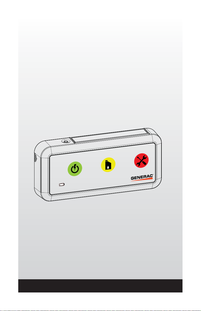
Mode d’emploi
Moniteur local sans fil
Modèle : 006664-0
REMARQUE :
Ce dispositif d’affichage et son émetteur-récepteur pour générateur sont une paire
assortie. Le dispositif d’affichage inclus fonctionnera seulement avec l’émetteurrécepteur pour générateur inclus.
www.generac.com ou 1-888-GENERAC
Page 42

Table des matières
TABLE DES MATIÈRES
SÉCURITÉ ..........................................................................................................................1
Lire ce manuel attentivement .........................................................................................2
Règles de sécurité ..........................................................................................................3
Fonctionnement et entretien ...........................................................................................4
Comment obtenir des services .......................................................................................5
INTRODUCTION .................................................................................................................5
Compatibilité du générateur ...........................................................................................6
INSTALLATION ...................................................................................................................6
Installation de l’émetteur-récepteur ................................................................................6
Instructions d’installation de l’émetteur-récepteur latéral du générateur -
Générateurs refroidis à l’air ......................................................................................6
Installation du dispositif d’affichage ..............................................................................10
Installation de la pile ..............................................................................................10
Essai pour l’intensité du signal...............................................................................10
Tableau de référence rapide de l’essai pour l’intensité du signal ..........................11
Montage du dispositif d’affichage ...........................................................................11
UTILISATION ....................................................................................................................12
Utilisation générale du moniteur local sans fil ..............................................................12
Voyants d’état de l’émetteur-récepteur du générateur ...........................................12
Voyant vert du dispositif d’affichage (générateur OK ou en fonction) ....................12
Voyant jaune du dispositif d’affichage (entretien requis ou
avertissement actif) ................................................................................................12
Voyant rouge du dispositif d’affichage (vérifiez l’état du générateur, appelez le
fournisseur si nécessaire) ......................................................................................13
Indicateur de pile faible ..........................................................................................13
DÉPANNAGE ....................................................................................................................14
TABLEAU DE RÉFÉRENCE RAPIDE ..............................................................................15
REMARQUES ...................................................................................................................16
GARANTIE ........................................................................................................................17
AVERTISSEMENT RELATIF À LA PROPOSITION 65 DE L’ÉTAT DE LA CALIFORNIE
Ce produit contient ou émet des produits chimiques reconnus par l’État de la Californie
comme pouvant causer le cancer, des anomalies congénitales ou d’autres problèmes
de reproduction.
Page 43

Sécurité
SÉCURITÉ
Comprend l’identification FCC : OA3MRF89XAM9A
Cet appareil est conforme à la partie 15 des règlements de la FCC.
Le fonctionnement de l’appareil est assujetti aux deux conditions suivantes :
1. Cet appareil ne peut pas causer d’interférences nuisibles.
2. Cet appareil doit accepter toute interférence reçue, y compris les interférences qui peuvent
être la cause d’un fonctionnement non souhaité.
Cet équipement a été évalué et déclaré conforme aux limites fixées pour les appareils
numériques de classe B, selon la partie 15 des règlements de la FCC. Ces limites sont
prévues pour fournir une protection raisonnable contre les interférences nuisibles dans les
installations résidentielles. Cet équipement génère, utilise et peut émettre de l’énergie de
fréquences radio et, s’il n’est pas installé et utilisé conformément aux instructions, peut causer
des interférences nuisibles aux communications radio. Cependant, il n’y a pas de garantie
qu’aucune interférence ne se produira dans une installation particulière. Si cet équipement
cause des interférences nuisibles à la réception de la radio et de la télévision, ce qui peut être
établi en l’allumant et en l’éteignant, l’utilisateur devrait essayer de corriger les interférences
à l’aide d’une ou de plusieurs des mesures suivantes :
• Réorienter ou déplacer l’antenne de réception.
• Augmenter la distance entre l’équipement et le récepteur.
• Brancher l’équipement à une prise reliée à un circuit différent de celui utilisé par le
récepteur.
• Consulter le vendeur ou un technicien radio/télévision expérimenté pour obtenir de l’aide.
Article 7.1.3 du CNR-GEN
Ce dispositif est conforme à l’exemption de licence d’Industrie Canada selon les normes RSS.
Le fonctionnement de l’appareil est assujetti aux deux conditions suivantes :
1. Cet appareil ne peut pas causer d’interférences.
2. Cet appareil doit accepter toute interférence, y compris les interférences qui peuvent être
la cause d’un fonctionnement non souhaité de l’appareil.
Pour être conforme aux exigences FCC en matière d’exposition pour les dispositifs émetteurs
mobiles et de base, une séparation de 20 m ou plus doit être maintenue entre l’antenne du
dispositif et les personnes durant le fonctionnement. Pour vous assurer d’être en conformité,
l’utilisation à une distance inférieure n’est pas recommandée. L’antenne utilisée pour cet
émetteur ne doit pas se trouver au même endroit ou fonctionner conjointement avec une autre
antenne ou un autre émetteur.
1
Page 44
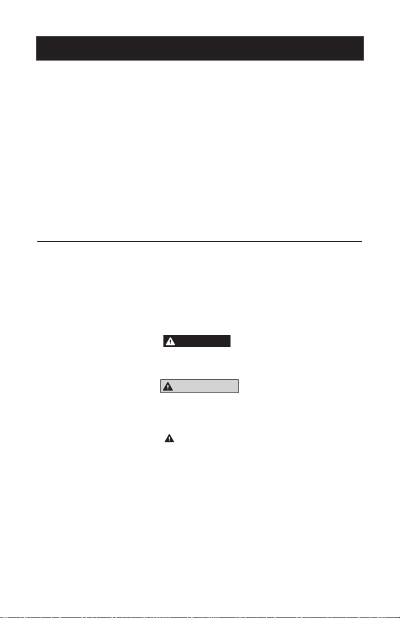
Règles de sécurité
C ONSERVEZ CES INSTRUCTIONS - Ce manuel est complémentaire au
Manuel du propriétaire du générateur. Tous les avertissements et les
recommandations contenus dans le manuel du fabricant doivent être
respectés pour un usage sécuritaire.
C ONSERVEZ CES INSTRUCTIONS - Le fabricant suggère que ces règles
de fonctionnement sécuritaire soient copiées et affichées dans les
zones où des dangers potentiels sont présents. Il faut insister sur la
sécurité auprès de tous les opérateurs, les opérateurs potentiels et les
techniciens d’entretien et de réparation de cet équipement.
C ONSERVEZ CES INSTRUCTIONS - Ce manuel contient des
instructions importantes qui doivent être suivies pendant l’installation
et l’entretien du générateur et des piles.
LIRE CE MANUEL ATTENTIVEMENT
En cas d’incompréhension d’une partie du manuel, communiquez avec le fournisseur de services
d’entretien agréé le plus près et demandez des explications sur les procédures de démarrage,
d’utilisation et d’entretien.
Des encarts DANGER, AVERTISSEMENT, MISE EN GARDE et REMARQUE apparaissent
ponctuellement dans cette publication ainsi que sur les étiquettes et autocollants apposés sur le
générateur afin d’attirer l’attention du personnel sur des consignes propres à certaines opérations
ou certains entretiens pouvant présenter des risques dans le cas où elles sont réalisées de manière
incorrecte ou inattentive. Respectez-les à la lettre. Voici leur définition :
DANGER!
INDIQUE UNE SITUATION OU UNE ACTION DANGEREUSE QUI, SI ELLE N’EST PAS ÉVITÉE,
ENTRAÎNERA LA MORT OU DES BLESSURES GRAVES.
AVERTISSEMENT!
Indique une situation ou une action dangereuse qui, si elle n’est pas évitée,
pourrait entraîner la mort ou des blessures graves.
MISE EN GARDE!
Indique une situation ou une action dangereuse qui, si elle ne peut être
évitée, risque d’entraîner des blessures légères ou moyennement graves.
REMARQUE :
Les remarques contiennent des informations supplémentaires importantes à propos des
procédures et sont intégrées au corps du texte de ce manuel.
Ces avertissements en matière de sécurité ne peuvent éliminer les dangers qu’ils décrivent. Le bon
sens et un respect strict des consignes sont essentiels afin de prévenir les accidents lors de l’utilisation
ou de l’entretien de l’équipement.
Quatre symboles de sécurité communément utilisés accompagnent les encarts DANGER,
AVERTISSEMENT et MISE EN GARDE. Voici les informations indiquées par chacun de
ceux-ci :
2
Page 45

Règles de sécurité
Ce symbole fournit des informations de sécurité importantes qui, si
elles ne sont pas suivies, pourraient mettre en danger la sécurité des
personnes ou les biens d’autrui.
Ce symbole indique un risque potentiel d’explosion.
Ce symbole indique un risque potentiel d’incendie.
Ce symbole indique un risque potentiel de décharge électrique.
RÈGLES DE SÉCURITÉ
Étudiez ces RÈGLES DE SÉCURITÉ avant l’installation, l’utilisation ou l’entretien de cet équipement.
Familiarisez-vous avec ce manuel du propriétaire et avec l’appareil. Le générateur peut être
utilisé de manière sécuritaire, efficace et fiable seulement si celui-ci est installé, utilisé et entretenu
correctement. De nombreux accidents sont causés par le non-respect des règles ou des précautions
simples et fondamentales.
Le fabricant ne peut pas anticiper toutes les circonstances possibles pouvant être source de
danger. Les avertissements de ce manuel, ainsi que ceux qui se trouvent sur les étiquettes et les
autocollants fixés sur l’appareil ne préviennent pas tous les risques. Lors d’une procédure, d’une
méthode de travail ou d’une technique d’utilisation n’étant pas spécifiquement recommandée
par le fabricant, veillez à vous assurer de la sécurité des autres. Assurez-vous également que la
procédure, la méthode de travail ou la technique d’utilisation ne fait pas en sorte que le générateur
devienne non sécuritaire.
DANGER!
En dépit de la conception sécuritaire du générateur, le fait d’utiliser cet
équipement de façon imprudente, de négliger son entretien ou d’être
inattentif peut causer des blessures ou la mort. Ne permettez qu’aux
personnes responsables et compétentes d’utiliser et d’entretenir cet
équipement.
Ces machines génèrent des tensions potentiellement mortelles.
Veillez à ce que toutes les mesures de sécurité soient prises avant de
tenter de travailler sur le générateur.
Certaines pièces du générateur peuvent tourner ou devenir chaudes
pendant l’utilisation. Faites preuve de prudence à proximité d’un
générateur en marche.
RISQUES GÉNÉRAUX
• Pour des raisons de sécurité, le fabricant recommande que l’installation, le démarrage initial et
l’entretien de cet équipement soient effectués par un fournisseur.
• Gardez les mains, les pieds, les vêtements, etc., loin des courroies d’entraînement, des
ventilateurs et d’autres pièces mobiles ou chaudes. Ne retirez jamais la courroie d’entraînement
ou la grille de protection du ventilateur lorsque l’appareil fonctionne.
• Restez vigilant en tout temps pendant l’entretien ou la réparation de cet appareil. Ne travaillez
jamais sur l’équipement en cas de fatigue physique ou mentale.
3
Page 46

Règles de sécurité
RISQUES ÉLECTRIQUES
• Ne touchez jamais un appareil électrique lorsque vous êtes debout sur un sol mouillé, pieds
nus ou lorsque vos mains ou vos pieds sont humides. UNE DÉCHARGE ÉLECTRIQUE
DANGEREUSE PEUT SE PRODUIRE.
• En cas d’accident causé par une décharge électrique, coupez immédiatement la source d’énergie
électrique. Si cela n’est pas possible, essayez de libérer la victime du conducteur sous tension.
ÉVITEZ TOUT CONTACT DIRECT AVEC LA VICTIME. Utilisez un outil non conducteur, tel qu’une
planche ou une corde sèche, pour libérer la victime du conducteur sous tension. Si la victime est
inconsciente, administrez-lui les premiers soins et obtenez une aide médicale immédiate.
• Ne portez jamais de bijoux pour travailler sur cet appareil. Les bijoux peuvent conduire
l’électricité et causer une décharge électrique, ou être happés par les pièces en mouvement et
causer des lésions.
RISQUES D’EXPLOSION
• Ne fumez pas près du générateur. Essuyez immédiatement tout déversement de carburant ou
d’huile. Assurez-vous qu’aucun matériau combustible n’est laissé dans le compartiment du
générateur, sur le générateur ou à proximité de ce dernier puisque cela pourrait occasionner
un INCENDIE ou une EXPLOSION. Gardez la zone entourant le générateur propre et exempte
de débris.
FONCTIONNEMENT ET ENTRETIEN
L’opérateur est responsable de faire une utilisation appropriée et sécuritaire de cet équipement.
Le fabricant recommande fortement que l’opérateur lise le présent Manuel du propriétaire et de
s’assurer de bien comprendre toutes les instructions avant d’utiliser cet équipement. Le fabricant
recommande également vivement que les autres utilisateurs soient formés pour pouvoir démarrer
et faire fonctionner correctement l’appareil. Cela les prépare au cas où ils devraient faire fonctionner
l’équipement en cas d’urgence.
L’opérateur a la responsabilité d’effectuer toutes les vérifications de sécurité afin de s’assurer que
tout l’entretien permettant une utilisation sécuritaire est effectué rapidement, et de faire vérifier
l’équipement périodiquement par un fournisseur de services d’entretien agréé. L’entretien normal,
la réparation et le remplacement des pièces sont la responsabilité du propriétaire ou de l’opérateur
et, à ce titre, ne sont pas considérés comme des défauts de matériaux ou de fabrication en vertu
des conditions de la garantie. Les habitudes de fonctionnement et les méthodes d’utilisation
individuelles peuvent entraîner un entretien ou des réparations supplémentaires.
Les instructions de fonctionnement présentées dans le manuel supposent que le système électrique
d’urgence a été installé par un fournisseur de services d’entretien agréé ou par un entrepreneur
compétent et qualifié. L’installation de cet équipement n’est pas un projet à faire soi-même.
4
Page 47

Introduction
COMMENT OBTENIR DES SERVICES
Lorsque le générateur requiert un entretien ou une réparation, veuillez communiquer avec un
fournisseur de services d’entretien agréé pour de l’assistance. Les techniciens d’entretien sont
formés à l’usine et peuvent effectuer tous les services d’entretien (1-800-333-1322).
Lorsque vous communiquez avec un fournisseur de services d’entretien agréé à propos des pièces
et de l’entretien, ayez toujours en main le numéro du modèle complet de l’appareil tel qu’il apparaît
sur le dessus de ce manuel ou sur LA PLAQUE SIGNALÉTIQUE apposée sur l’appareil.
INTRODUCTION
Le moniteur local sans fil comprend un émetteur-récepteur monté sur le générateur et un appareil
d’affichage installé dans un endroit de visualisation pratique dans la maison ou l’entreprise. Le
système possède une ligne de visée d’environ 600 pieds, mais cette distance peut être réduite
lorsque le signal doit passer à travers les murs, les planches, etc. d’une installation type. Grâce à
ce système de surveillance à distance, l’état du générateur peut être facilement vérifié à partir de
votre domicile ou d’une entreprise.
L’émetteur-récepteur du générateur et le dispositif d’affichage sont expédiés de l’usine par paires.
Ces appareils sont préalablement mis en paires pour assurer la communication et pour éviter une
communication croisée avec les autres dispositifs qui se trouvent à proximité.
REMARQUE :
Certains matériaux peuvent complètement bloquer le passage du signal, par exemple
les poutres en aciers, le bardage métallique et les barrières d’isolation à rayonnement
d’aluminium.
• Le moniteur local sans fil indique l’état du générateur grâce à trois voyants : vert, jaune et rouge.
• Le bouton d’essai effectue un essai pour l’intensité du signal.
• L’indicateur de l’état de la pile indique un état faible de la pile.
• L’avertisseur émet des signaux d’avertissement sonores conjointement aux voyants jaune ou
rouge.
AVERTISSEUR - émet
un signal sonore avec
le VOYANT JAUNE ou
ROUGE
INDICATEUR DE L’ÉTAT DE LA BATTERIE
VOYANT ROUGE - Alarme/le générateur s’éteint
BOUTON D’ESSAI
VOYANT JAUNE - Avertissement ou
entretien requis/le générateur fonctionne
VOYANT VERT - Générateur OK/le générateur fonctionne
Fonctions du moniteur local sans fil
5
Page 48

Installation
COMPATIBILITÉ DU GÉNÉRATEUR
• Cet appareil peut être installé sur tous les générateurs de secours résidentiels refroidis à l’air de
2008 ou plus récents munis d’un écran ACL et sur tous les générateurs de secours à carburant
gazeux refroidis par liquide de 2010 ou plus récents. L’appareil peut aussi être utilisé avec les
générateurs de secours à carburant diesel refroidis à l’air contrôlé Evolution de 2013 ou plus
récents.
• Certains appareils refroidis par liquide nécessitent l’utilisation d’un faisceau de câbles pour
adaptateur (modèle 006665-0). Voici lesquels :
– Tous les générateurs des séries Protector et QT qui ne sont pas dotés d’un emplacement
de montage pré-poinçonné.
– Les appareils dont la capacité dépasse 60 kW.
Remarque : Le faisceau de câbles pour adaptateur est recommandé, mais non nécessaire
avec les appareils dont la capacité est égale ou inférieure à 60 kW.
• Limites de température ambiante : 50 °C/122 °F
INSTALLATION DE L’ÉMETTEUR-RÉCEPTEUR
INSTRUCTIONS D’INSTALLATION DE L’ÉMETTEUR-RÉCEPTEUR LATÉRAL DU
GÉNÉRATEUR - GÉNÉRATEURS REFROIDIS À L’AIR
Les étapes suivantes expliquent comment installer l’émetteur-récepteur latéral pour générateur sur
un générateur refroidi à l’air.
Pour les utilisations avec un générateur refroidi par liquide, une trousse d’adaptateur est nécessaire;
celle-ci est fournie avec des instructions supplémentaires.
REMARQUE :
La pile du générateur sera déconnectée puis reconnectée durant le processus d’installation,
ce qui peut causer l’affichage de l’avertissement « Inspection de la pile » sur le régulateur du
générateur. Cela est normal et n’est pas un problème. Il suffit de supprimer l’avertissement
du régulateur du générateur en suivant les instructions de fonctionnement du régulateur.
L’heure et la date doivent aussi être réinitialisées lorsque la batterie de démarrage est
reconnectée.
1. Retirez le fusible T1 du commutateur de transfert.
2. Déverrouillez les deux verrous et ouvrez le rabat supérieur du générateur.
3. Mettez le générateur en mode ARRÊT.
4. Retirez le fusible de 7,5 A du tableau de commande.
5. Retirez le panneau d’accès frontal du boîtier.
6. Débranchez le câble de batterie noir négatif (-). Débranchez ensuite le câble rouge positif (+).
7. Le cas échéant, mettez le disjoncteur principal HORS TENSION dans le tableau de distribution
du disjoncteur du réseau public de votre domicile. Cela est nécessaire si l’installation est
effectuée une fois que le générateur a été connecté au réseau public.
REMARQUE :
La configuration des régulateurs varie en fonction de l’année du modèle. Suivez les étapes
suivantes qui correspondent à l’année du modèle de votre générateur.
6
Page 49
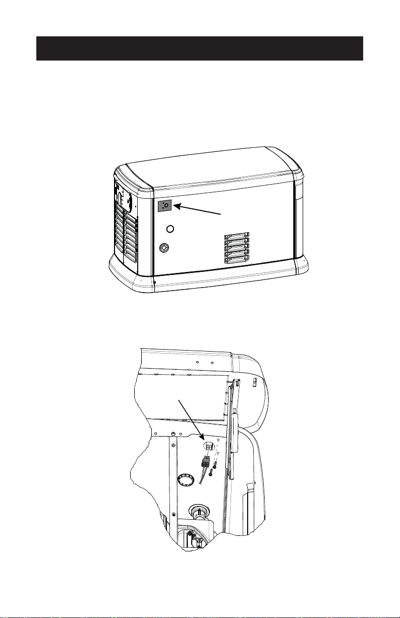
Installation
Installation de l’émetteur-récepteur - 2008 à 2012 avec affichage ACL
1. Trouvez les caractéristiques de montage et la plaque de recouvrement qui se trouvent à
l’arrière du générateur. Enlevez la plaque de recouvrement et positionnez l’émetteur-récepteur
à l’arrière du générateur en vous assurant que le joint fournisse une étanchéité adéquate.
EMPLACEMENT
DE MONTAGE
Emplacement de montage de l’émetteur-récepteur
2. Installez 2 vis à partir de l’intérieur du générateur pour fixer l’émetteur-récepteur à la paroi
du générateur.
État de l’émetteur récepteur
Emplacement de l’éclairage
Attaches de montage de l’émetteur-récepteur, emplacement du voyant d’état de
l’émetteur-récepteur et connecteur de câblage.
7
Page 50

Installation
Installation de l’émetteur-récepteur - 2013 et plus récent
REMARQUE :
Certains des appareils de 2013 ne possèdent pas de trous de montage pour l’émetteurrécepteur. Le gabarit (fourni) doit être utilisé.
1. Posez le gabarit à l’arrière du boîtier du générateur dans le coin supérieur gauche. Alignez le
gabarit avec le bord gauche et le bord supérieur du boîtier. Fixez le gabarit à l’aide de ruban
adhésif et faites une marque sur le boîtier pour indiquer l’emplacement des trous à percer.
2. Inspectez la zone derrière le gabarit pour vous assurer qu’il y a un jeu suffisant pour percer.
Déplacez tous les fils pour éviter les dommages.
3. À l’aide du gabarit, percez l’ouverture pour le câble et les trous de montage.
4. Placez l’émetteur-récepteur à l’arrière du générateur en vous assurant que les joints
fournissent l’étanchéité nécessaire.
5. Installez l’émetteur-récepteur sur la paroi du générateur à l’aide de 2 vis pour fixer l’appareil.
Procédure de câblage - Toutes les années
1. Branchez le connecteur à 4 broches à l’émetteur-récepteur.
2. Sur les appareils de secours résidentiels de 2008 seulement, enlevez les attaches qui
retiennent le régulateur et soulevez ce dernier pour avoir accès au port auxiliaire.
4. Si vous voyez un autocollant marqué « Port 1 », retirez-le pour repérer le connecteur. S’il n’y
a pas d’autocollant, placez le connecteur ouvert à 8 broches sur le dessous du régulateur.
5. Acheminez le câble pour qu’il s’accouple avec le connecteur au bas du régulateur.
6. Installez le connecteur à 8 broches du câblage dans la prise ouverte située sur le régulateur.
Consultez les dessins du régulateur pour trouver l’emplacement adéquat pour le connecteur
à câblage préassemblé du connecteur ouvert à 8 broches.
REMARQUE :
Le connecteur ne s’installera que dans un sens. NE forcez PAS.
8
Régulateur 2008
Page 51
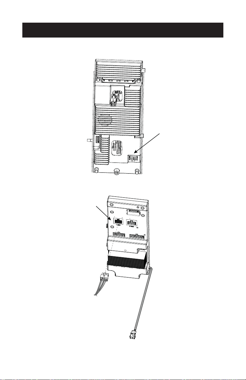
Régulateur 2010
Installation
Régulateur 2013
9
Page 52

Installation
Installation finale - Toutes les années
1. Rebranchez le câble de batterie rouge positif (+) en premier. Rebranchez ensuite le câble noir
négatif (-).
2. Installez le régulateur et le couvercle. Fixez à l’aide d’attaches (appareils de secours résidentiels de
2008 seulement).
3. Réinstallez le panneau d’accès frontal du générateur.
4. Installez le fusible de 7,5 A du tableau de commande.
5. Réinstallez le fusible T1 dans le commutateur de transfert.
6. Le cas échéant, mettez le disjoncteur principal du tableau de distribution résidentiel EN MARCHE.
7. Mettez le générateur en mode AUTO.
8. Utilisez l’assistant d’installation pour régler la date, l’heure et la fonction d’exercice.
INSTALLATION DE L’APPAREIL D’AFFICHAGE
INSTALLATION DES PILES
L’appareil d’affichage du moniteur local sans fil est alimenté par deux piles alcalines AAA non
rechargeables qui sont installées en enlevant le couvercle des piles qui se trouve à l’arrière de l’appareil.
Respectez la polarité des piles qui est indiquée près du compartiment à pile. La durée de vie des piles
pour un usage normal est de six mois si vous utilisez des piles alcalines AAA de 1,2 Ah et 1,5 V.
REMARQUE :
Les piles doivent être changées lorsque l’avertissement de l’indicateur de pile faible est activé.
Le moniteur local sans fil ne possède pas d’interrupteur. Le moniteur se met en marche automatiquement
lorsque les piles sont installées.
ESSAI POUR L’INTENSITÉ DU SIGNAL
L’appareil d’affichage est équipé d’un mode d’essai pour l’intensité du signal. Appuyez sur le bouton Essai
durant 5 secondes pour entrer dans le mode d’essai de l’intensité du signal. Les voyants vert, jaune et
rouge s’allumeront en alternance durant un court moment pour indiquer la transition entre le mode état
et le mode d’essai pour l’intensité du signal. L’appareil sera dans ce mode durant 30 secondes. Durant
l’essai pour l’intensité du signal :
• Vert - Bonne intensité du signal
• Jaune - Intensité du signal minime
• Rouge - Aucun signal détecté
Après 30 secondes, l’appareil sortira automatiquement du mode d’essai pour l’intensité du signal.
Lorsque cela se produit, les indicateurs s’allumeront en alternance pour indiquer la transition vers le
mode état.
Une utilisation prolongée ou fréquente de l’essai pour l’intensité du signal peut diminuer la
durée de vie de la pile.
L’appareil d’affichage fonctionnera même si l’intensité du signal est jaune, mais la durée de vie
de la pile pourrait être réduite.
10
REMARQUE :
REMARQUE :
Page 53

Installation
TABLEAU DE RÉFÉRENCE RAPIDE DE L’ESSAI POUR L’INTENSITÉ DU SIGNAL
L’essai pour l’intensité du signal est actif - Le bouton de l’appareil d’affichage doit être maintenu
enfoncé durant plus de 5 secondes - Les voyants de l’appareil d’affichage passeront de l’indication
de l’état actuel du générateur à une série rotative pour signaler un changement de fonction et le
passage en mode d’essai pour l’intensité du signal. Il répétera cette série rotative lorsque vous
sortez du mode d’essai pour l’intensité du signal.
Voyant vert
MARCHE ARRÊT ARRÊT
ARRÊT MARCHE ARRÊT
ARRÊT ARRÊT MARCHE
Voyant
jaune
Voyant
rouge
Signifi cation
Signal fort de l’émetteur-récepteur vers l’appareil
d’affi chage.
Signal faible de l’émetteur-récepteur vers l’appareil
d’affi chage
Aucun signal de l’émetteur-récepteur vers l’appareil
de base
MONTAGE DU DISPOSITIF D’AFFICHAGE
Il y a trois façons de monter l’appareil d’affichage :
• Montage sur bureau (inclus)
• Montage mural
• Montage à l’aide d’un aimant (inclus)
REMARQUE :
L’appareil d’affichage est prévu pour un montage intérieur seulement. Évitez de monter
l’appareil d’affichage dans un endroit mouillé ou humide.
REMARQUE :
Assurez-vous d’effectuer un essai pour l’intensité du signal lorsque l’appareil d’affichage
se trouve à l’emplacement prévu. Par exemple, faites l’essai lorsque l’appareil est appuyé
contre le réfrigérateur ou un mur pour vérifier l’intensité du signal. Si l’intensité du signal
est faible ou nulle lorsque l’appareil est appuyé sur une surface, le montage sur bureau
devrait être utilisé pour assurer la communication.
1. Effectuez un essai pour l’intensité du signal (consultez la section Essai pour l’intensité du
signal de ce manuel) pour déterminer l’emplacement idéal dans votre domicile.
2a. Pour l’utilisation du montage sur bureau, installez le montage dans les trous qui se trouvent à
l’arrière de l’appareil d’affichage et mettez-le en place.
2b. Pour le montage mural, mesurez la distance entre les montures à vis à l’arrière de l’appareil
d’affichage et installez deux vis dans le mur à partir desquelles l’appareil sera suspendu.
2c. Pour l’utilisation du montage avec aimant, enlevez l’adhésif de l’aimant et posez-le à l’arrière
de l’appareil d’affichage, dans la pochette fournie.
REMARQUE :
L’installation de l’aimant cachera les trous des vis des montages muraux. Il doit donc être
enlevé si la méthode de montage mural est utilisée.
11
Page 54

Fonctionnement
FONCTIONNEMENT GÉNÉRAL DU MONITEUR LOCAL SANS FIL
L’état normal de l’appareil d’affichage est lorsqu’aucun voyant n’est actif. Cela indique
qu’il n’y a aucun problème avec le générateur. Lorsqu’un problème se produit, les voyants
indiqueront le problème selon l’information contenue dans cette section.
VOYANT D’ÉTAT DE L’ÉMETTEUR-RÉCEPTEUR DU GÉNÉRATEUR
L’émetteur-récepteur du générateur possède un voyant d’état vert qui indique qu’il est alimenté et
qu’il est en communication avec l’appareil d’affichage. Ce voyant peut être vu à partir de l’intérieur
du compartiment du générateur, à travers l’ouverture pour le câblage préassemblé lorsque le rabat
du générateur est levé.
• Voyant vert fixe - alimentation présente/communication établie
• Voyant vert clignotant - alimentation présente/aucune communication
VOYANT VERT DE L’APPAREIL D’AFFICHAGE (GÉNÉRATEUR OK OU EN
FONCTION)
Durant le fonctionnement normal, si le générateur est en mode AUTO et qu’aucun entretien,
avertissement ou alarme n’est en cours, aucun voyant ne sera allumé.
Pour vérifier l’état du générateur, il est possible d’appuyer sur le bouton Essai pour afficher l’état.
Si le générateur est en mode AUTO et qu’aucun avertissement ou alarme n’est présent, le voyant
vert s’allumera lorsque vous appuierez sur le bouton Essai.
Le voyant vert clignotera toutes les cinq (5) secondes lorsque le générateur fonctionnera en mode
AUTO ou MANUEL.
VOYANT JAUNE DE L’APPAREIL D’AFFICHAGE (ENTRETIEN REQUIS OU
AVERTISSEMENT ACTIF)
Le voyant jaune indique :
• Qu’un avertissement pour le générateur est présent.
• Que l’entretien du générateur est requis.
Le générateur fonctionne tout de même lorsque le voyant jaune est allumé.
Lorsqu’il est actif, mais que le générateur ne fonctionne pas, le voyant jaune clignotera une fois
toutes les cinq (5) secondes. Si le générateur fonctionne lorsque le voyant jaune est actif, le voyant
vert et le voyant jaune clignoteront une fois toutes les cinq (5) secondes.
L’avertisseur interne émettra un son toutes les quatre (4) heures durant une (1) seconde lorsque
le voyant jaune est actif. Durant une période d’inactivité, l’avertisseur peut être arrêté en appuyant
brièvement et en relâchant le bouton Essai. L’avertisseur émettra deux battements pour indiquer
qu’il est en mode muet. L’avertisseur ne se réactivera pas tant qu’une nouvelle alarme n’est pas
détectée.
REMARQUE :
Si vous appuyez sur le bouton pendant que l’avertisseur émet un son, il pourrait ne pas
être désactivé.
12
Page 55

Fonctionnement
VOYANT ROUGE DE L’APPAREIL D’AFFICHAGE (VÉRIFIEZ L’ÉTAT DU
GÉNÉRATEUR, APPELEZ UN FOURNISSEUR SI NÉCESSAIRE)
Le voyant rouge indique :
• Que le bouton AUTO/ARRÊT/MANUEL du générateur est en mode ARRÊT
• Qu’une alarme pour le générateur est présente.
Si une alarme est présente, le générateur ne démarrera pas et ne fonctionnera pas si une panne du
réseau public se produit ou s’éteindra automatiquement si le moteur est déjà en marche.
Lorsqu’il est actif, le voyant rouge clignotera une fois toutes les cinq (5) secondes.
L’avertisseur interne émettra un son toutes les heures durant cinq (5) secondes lorsque le voyant
rouge est allumé. Durant une période d’inactivité, l’avertisseur peut être arrêté en appuyant
brièvement et en relâchant le bouton Essai. L’avertisseur émettra deux battements pour indiquer
qu’il est en mode muet. L’avertisseur ne se réactivera pas tant qu’une nouvelle alarme n’est pas
détectée.
REMARQUE :
Si vous appuyez sur le bouton pendant que l’avertisseur émet un son, il pourrait ne pas
être désactivé.
INDICATEUR DE PILE FAIBLE
L’indicateur de l’état de la pile clignotera toutes les cinq (5) secondes et l’avertisseur émettra un
son toutes les 15 minutes lorsqu’une pile faible est détectée. Les piles doivent être remplacées
immédiatement.
Une fois que les piles ont été remplacées, vérifiez l’état du générateur en appuyant sur le bouton
Essai pour vérifier le fonctionnement.
Durant une période d’inactivité, l’avertisseur peut être arrêté en appuyant brièvement et en relâchant
le bouton Essai. L’avertisseur émettra deux battements pour indiquer qu’il est en mode muet.
L’avertisseur ne se réactivera pas tant qu’une nouvelle alarme n’est pas détectée.
13
Page 56

Dépannage
DÉPANNAGE
Problème Causes possibles Mesures correctives
Le voyant de l’émetteurrécepteur n’est pas
allumé.
Le voyant de l’émetteurrécepteur du générateur
clignote.
Appareil d’affi chage Les voyants jaune et
rouge clignotent.
Appareil d’affi chage Tous les voyants
clignotent
(communication perdue
entre l’émetteurrécepteur du générateur
et l’appareil d’affi chage).
Appareil d’affi chage Aucun voyant ne
s’allume lorsque vous
appuyez sur le bouton.
Piles - La durée de vie
des piles est inférieure
à celle prévue.
Intensité du signal
faible.
14
L’émetteur-récepteur n’est pas
alimenté. Il est possible qu’il n’y ait pas
de connexion avec l’émetteur-récepteur
du générateur.
L’émetteur-récepteur n’est pas
alimenté. Le fusible a sauté, a été
endommagé ou a été enlevé du
régulateur du générateur.
L’émetteur-récepteur n’est pas
alimenté. La batterie du générateur est
déconnectée.
L’émetteur-récepteur n’est pas
en communication avec l’appareil
d’affi chage.
L’émetteur-récepteur du générateur ne
communique pas avec le générateur.
L’appareil d’affi chage est hors de la
portée de l’émetteur-récepteur du
générateur.
L’émetteur-récepteur du générateur ne
communique pas avec le régulateur
du générateur ou ne reçoit aucune
alimentation.
L’émetteur-récepteur n’est pas
alimenté. Le fusible a sauté, a été
endommagé ou a été enlevé du
régulateur du générateur.
L’émetteur-récepteur n’est pas
alimenté. La batterie du générateur est
déconnectée.
Piles déchargées. Vérifi ez et remplacez les piles.
Intensité du signal faible.
Diminution du signal causé par le
passage à travers divers matériaux ou
objets tels que le bardage métallique,
des fenêtres fi ltrées, de la brique,
plusieurs murs ou par les conditions
météorologiques.
Vérifi ez que la connexion du câble de
l’émetteur-récepteur est adéquate entre
ce dernier et le régulateur.
Vérifi ez et remplacez le fusible.
Vérifi ez les connexions des piles du
générateur.
Installez ou remplacez les piles. Il se peut
que l’appareil d’affi chage soit hors portée.
Vérifi ez le câble et les connexions entre
le tableau de commande du générateur
et l’émetteur récepteur.
Vérifi ez l’état de la portée en effectuant
l’essai pour l’intensité du signal et
déplacez l’appareil d’affi chage pour qu’il
soit plus près du générateur jusqu’à ce
que la portée soit acceptable.
Vérifi ez que la connexion à l’émetteurrécepteur a bien été effectuée.
Vérifi ez que la connexion au régulateur a
bien été effectuée.
Vérifi ez et remplacez le fusible.
Vérifi ez les connexions des piles du
générateur.
Effectuez l’essai pour l’intensité du signal
et trouvez un nouvel emplacement où
l’intensité du signal est plus élevée, si
nécessaire.
Effectuez l’essai pour l’intensité du signal
et trouvez un nouvel emplacement où
l’intensité du signal est plus élevée, si
nécessaire.
Page 57

Tableau de référence rapide
TABLEAU DE RÉFÉRENCE RAPIDE
Voyant
vert
ARRÊT ARRÊT
Clignote
toutes
les 5
secondes.
ARRÊT
ARRÊT
Clignote
toutes
les 5
secondes.
MARCHE ARRÊT ARRÊT - ARRÊT
Clignote
toutes
les 3
secondes.
Voyant
jaune
---
Clignote
toutes
les 5
secondes.
Clignote
toutes
les 5
secondes.
Clignote
toutes
les 5
secondes.
ARRÊT ARRÊT - ARRÊT
Clignote
toutes
les 3
secondes.
Voyant
rouge
Clignote
toutes
les 5
secondes.
ARRÊT -
ARRÊT -
Clignote
toutes
les 5
secondes.
Clignote
toutes
les 3
secondes.
Indicateur de
l’état de la pile
Clignote toutes
les 5 secondes.
-
- ARRÊT
- ARRÊT
Avertisseur Signifi cation
1 seconde
toutes les 15
minutes
5 secondes
toutes les
heures
1 seconde
toutes les
4 heures
1 seconde
toutes les
4 heures
Remplacez les piles de
l’appareil d’affi chage. Enlevez
les piles pour désactiver
l’avertisseur.
Le générateur ne fonctionnera
pas. État d’alarme signalé.
Appuyez sur le bouton Essai
pour désactiver l’avertisseur.
L’avertisseur se réactivera
lorsqu’il y aura un nouvel
avertissement.
Le générateur fonctionne
avec un avertissement.
Appuyez sur le bouton Essai
pour désactiver l’avertisseur.
L’avertisseur se réactivera
lorsqu’il y aura un nouvel
avertissement.
Le générateur ne fonctionne
pas, mais pourra fonctionner
au besoin. Avertissement du
générateur signalé. Appuyez
sur le bouton Essai pour
désactiver l’avertisseur.
L’avertisseur se réactivera
lorsqu’il y aura un nouvel
avertissement.
L’émetteur-récepteur du
générateur ne communique
pas avec le régulateur du
générateur.
Le générateur fonctionne
normalement.
Le générateur est en mode
d’attente et il est prêt à
fonctionner. Aucun problème
signalé.*
L’appareil d’affi chage
n’est plus en contact avec
l’émetteur-récepteur.
* Vous devez appuyer sur le bouton de l’appareil d’affi chage pour obtenir cet état.
15
Page 58

Remarques
16
Page 59

Garantie
GARANTIE LIMITÉE D'« UN AN » DE GENERAC
POWER SYSTEMS POUR LE MONITEUR À DISTANCE
SANS FIL (POUR LES GÉNÉRATEURS RÉSIDENTIELS
ET COMMERCIAUX)
La société Generac Power Systems, Inc. (ci-après dénommée « Generac ») garantit que,
pendant une période d'une année à compter de la date d'achat d'origine, ses moniteurs à
distance sans fil ne présenteront aucun défaut de matériel ni de fabrication pour les éléments
et les périodes mentionnées ci-après. À sa discrétion, Generac réparera ou remplacera toute
pièce qui sera reconnue défectueuse après examen, inspection et essai par Generac ou
par un fournisseur de services de garantie agréé Generac. Tout équipement que l'acheteur/
le propriétaire juge défectueux doit être retourné pour examen au fournisseur de services de
garantie agréé Generac le plus proche. Tous les frais de transport à payer dans le cadre de
cette garantie, incluant le retour à l'usine, seront supportés et payés à l'avance par l'acheteur/
le propriétaire. Cette garantie s'applique uniquement au moniteur à distance sans fil de
Generac et ne peut être cédée par l'acheteur d'origine.
La période de garantie commence à la date de l'achat de détail par le premier utilisateur final et
se poursuit pour la période de temps énoncée ci-dessus. « L'application grand public » signifie
toute utilisation domestique personnelle et résidentielle par un consommateur de détail. Aucune
autre utilisation n'est garantie.
APPLICATION GRAND PUBLIC
Un (1) an - Couverture globale limitée des pièces
CETTE GARANTIE NE S'APPLIQUE PAS DANS LES CAS
SUIVANTS :
1. Tout appareil fabriqué avant le 1er janvier 2014.
2. Tout frais de déplacement afin de dépanner, de retirer, de remplacer ou d'ajuster une ou
plusieurs pièces.
3. Articles d'entretien normal du client.
4. Défaillances en raison, mais sans s'y limiter, de ce qui suit :
• Entreposage • Utilisation incorrecte
• Installation inappropriée • Abus
• Réparation ou diagnostic inapproprié • Accident
• Entretien inapproprié • Application incorrecte
• Usure normale • Négligence
5. Les pannes provoquées par une cause externe ou une catastrophe naturelle telles qu'une
collision, un cambriolage, un acte de vandalisme, une émeute, une explosion nucléaire,
un incendie, un gel, la foudre, un tremblement de terre, une tempête, la grêle, une
éruption volcanique, de l'eau ou une inondation, une tornade, ou un ouragan.
6. Les produits et/ou la ou les pièces qui sont modifiés d'une manière non approuvée par
écrit par Generac.
7. Tous dommages accessoires, subséquents ou indirects causés par une défectuosité en
matériel et en fabrication ou par tout retard dans la réparation ou le remplacement d'une
ou de pièces défectueuses.
17
Page 60

Garantie
8. Les défaillances dues à une application incorrecte.
9. Frais de téléphone, de télégramme, de téléscripteur ou de tout autre moyen de
communication.
10. Les frais d'hébergement ou de transport de la ou des personnes réalisant l'entretien, sauf
s'ils sont spécifiquement inclus en vertu des conditions d'une période de garantie d'une
unité spécifique.
11. La location de l'équipement utilisé pendant que les réparations sous garantie sont
effectuées.
12. Frais de transport pour la ou les pièces de remplacement.
13. Frais de main-d'œuvre.
CETTE GARANTIE REMPLACE TOUTES LES AUTRES GARANTIES, EXPRESSES OU
IMPLICITES. EN PARTICULIER, GENERAC N'OFFRE AUCUNE AUTRE GARANTIE QUANT À
LA QUALITÉ MARCHANDE OU À LA CONVENANCE À UN USAGE PARTICULIER. Toutes les
garanties implicites qui sont autorisées par la loi seront limitées en durée au terme de la garantie
expresse à laquelle elles sont rattachées. Certains États ne permettent pas de poser une limite
à la durée de la garantie implicite; il se pourrait donc que la limite susmentionnée ne s'applique
pas à vous. LA SEULE RESPONSABILITÉ DE GENERAC RÉSIDERA DANS LA RÉPARATION
OU LE REMPLACEMENT DES PIÈCES COMME SPÉCIFIÉ CI-DESSUS. EN AUCUN CAS
GENERAC NE POURRA ÊTRE TENUE RESPONSABLE DE DOMMAGES ACCESSOIRES
OU SUBSÉQUENTS, MÊME SI LES DOMMAGES RÉSULTENT DIRECTEMENT DE LA
NÉGLIGENCE DE GENERAC.
Certains États ne permettent pas que des exclusions ou limitations aux dommages accessoires
ou consécutifs soient appliquées; il se pourrait donc que la limite susmentionnée ne s'applique
pas à vous. Cette garantie vous donne des droits juridiques précis. Vous pouvez également
avoir d'autres droits d'un État à l'autre.
GENERAC POWER SYSTEMS, INC.
S45 W29290 Hwy. 59 • Waukesha, WI 53189
Tél. : (888) GENERAC (436-3722) • Téléc. : (262) 544-4851
Pour trouver le fournisseur agréé le plus près, visitez notre site Web au
www.generac.com
Numéro de pièce 0K5816 Rév. C (11/13)
PROCÉDURE POUR SOUMETTRE UNE RÉCLAMA TION :
Si vous rencontrez un problème avec votre moniteur à distance, veuillez consulter les sections de l'installation
et de la programmation afi n de vous assurer que les lignes directrices ont été suivies.
Si un problème persiste, veuillez composer le 888-GENERAC (888-436-3722) pour de l'aide. Assurez-vous
d'avoir votre preuve d'achat à portée de main en cas de vérifi cation.
Après avoir parlé avec un représentant du service à la clientèle, une décision sera prise concernant l'envoi d'un
moniteur à distance de remplacement sans frais.
Generac Power Systems recommande que l'installation du moniteur à distance soit effectuée par un
fournisseur ou un installateur qualifi é.
REMARQUE : Les frais de déplacement et de main-d'œuvre NE SONT PAS autorisés en vertu de cette
garantie du fabricant.
Manuel Pièce no 0K5815 Révision C (29/07/14)
 Loading...