

Page 1
Owner’s Manual
For
Stationary Diesel Generators
Residential and Commercial
Model
RD015 - 15 kW 60 Hz
RD020 - 20 kW 60 Hz
RD030 - 30 kW 60 Hz
RD048 - 48 kW 60 Hz (Single Phase Only)
RD050 - 50 kW 60 Hz (Three Phase Only)
Protector™ Series
0066780 - 30 kW 60 Hz
NOT INTENDED FOR USE IN CRITICAL
LIFE SUPPORT APPLICATIONS.
ONLY QUALIFIED ELECTRICIANS OR
CONTRACTORS SHOULD ATTEMPT
INSTALLATION!
DEADLY EXHAUST FUMES! OUTDOOR
INSTALLATION ONLY!
This manual should remain with the unit.
This manual must be used in conjunction
with the appropriate installation manual.
Page 2
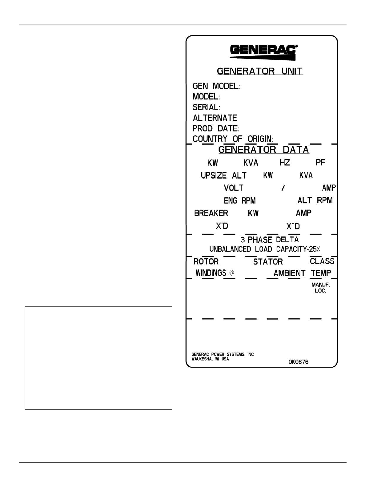
Use this page to record important information about
the generator set.
For quick and easy reference, copy the information
printed on the Unit Identification Label onto the sample
label printed here. The Unit Identification Label is
located at the rear of the alternator on 15/20 kW (2.3L)
units, and on the front engine mount on 30 kW (2.4L)
and 50 kW (3.4L) models. The label provides the following information:
• Model Number
• Serial Number
• Rated KW
• Voltage Rating
• Maximum Current Rating (AMPS)
When contacting an Authorized Service Dealer about
parts and/or service, always provide the complete model
number and serial number.
Operation and Maintenance: Proper maintenance and
care of the generator ensures safe operation and longer
service life while also keeping operating expenses to a
minimum. It is the operator’s responsibility to perform all
safety checks, to make sure that all maintenance is performed promptly, and to have the equipment checked
periodically by an Authorized Service Dealer.
Normal maintenance, service and replacement of parts
are the responsibility of the owner/operator, and are not
considered defects in materials or workmanship within
the terms of the warranty. Individual operating habits
and usage may contribute to the need for additional
maintenance or service.
When the generator requires servicing or repairs, contact an Authorized Service Dealer for assistance. Authorized service technicians are factory-trained and are
capable of handling all service needs.
AUTHORIZED
SERVICE DEALER LOCATION
To locate the nearest
AUTHORIZED SERVICE DEALER,
please call this number:
1-800-333-1322
or visit the dealer locator at:
www.generac.com/Service/DealerLocator/
ii Owner’s Manual for Stationary Diesel Generators
SAMPLE LABEL
Page 3

Table of Contents
Table of Contents
Section 1 Safety
1.1 Introduction .......................................................................................................................... 1
1.2 Safety Information ................................................................................................................ 2
1.3 General Hazards ................................................................................................................... 2
1.4 Exhaust Hazards .................................................................................................................. 3
1.5 Electrical Hazards ................................................................................................................ 3
1.6 Fire Hazards .......................................................................................................................... 3
1.7 Explosion Hazards ............................................................................................................... 3
Section 2 Specifications
2.1 Emission Information .......................................................................................................... 5
2.1.1 Emissions Data Plate .................................................................................................................... 5
2.2 Specifications ....................................................................................................................... 6
2.2.1 Engine ........................................................................................................................................... 6
2.3 Engine Oil Recommendations ............................................................................................ 7
2.4 Coolant Water Treatment ....................................................................................................7
2.5 Fuel Requirements ............................................................................................................... 8
2.5.1 Fuel Maintenance ......................................................................................................................... 8
2.6 Battery Requirements .......................................................................................................... 8
2.6.1 Battery Charger ............................................................................................................................8
2.7 Corrosion Protection ........................................................................................................... 8
2.8 Accessories .......................................................................................................................... 8
Section 3 Activation and Startup
3.1 Orientation .......................................................................................................................... 11
3.2 Remove Side Access Panels ............................................................................................ 11
3.3 Prime Fuel System ............................................................................................................. 12
3.4 Install Battery ..................................................................................................................... 12
3.5 Open Viewing Window ....................................................................................................... 13
3.6 Start and Run Engine ......................................................................................................... 13
3.7 Activate Unit ...................................................................................................................... 14
3.8 Operational Checks ........................................................................................................... 15
3.8.1 Self Test ......................................................................................................................................15
3.8.2 Check Manual Transfer Switch Operation ..................................................................................15
3.8.3 Electrical Checks ........................................................................................................................ 16
Owner’s Manual for Stationary Diesel Generators iii
Page 4

Table of Contents
3.8.4 Test Generator Under Load ........................................................................................................ 16
3.8.5 Check Automatic Operation ........................................................................................................ 17
3.9 Final Instructions ................................................................................................................17
Section 4 Operation
4.1 Control Panel ......................................................................................................................19
4.2 Auto/Manual/Off Keypad ....................................................................................................19
4.3 LCD Screen and Navigation Keypad ................................................................................ 20
4.4 Alarm/Warning Conditions ................................................................................................22
4.5 Change Time and Date .......................................................................................................22
4.6 Programmable Timers ........................................................................................................22
4.6.1 Dealer Programmable ................................................................................................................22
4.6.1.1 Exercise Time ..................................................................................................................... 22
4.6.2 User Programmable ...................................................................................................................23
4.6.2.1 Start-Up Delay Timer .......................................................................................................... 23
4.6.2.2 Warm-Up Delay Timer ........................................................................................................ 23
4.7 USB Port for Firmware Updates ........................................................................................23
4.8 Battery Charger ..................................................................................................................23
4.9 Transfer Switch Automatic Operation .............................................................................. 23
4.9.1 Automatic Sequence of Operation .............................................................................................. 24
4.9.1.1 Utility Failure ....................................................................................................................... 24
4.9.1.2 Cranking.............................................................................................................................. 24
4.9.1.3 Load Transfer...................................................................................................................... 24
4.10 Transfer Switch Manual Operation .................................................................................24
4.10.1 Transfer to Generator Power .................................................................................................... 25
4.10.2 Transfer Back to Utility Power ..................................................................................................25
Section 5 Maintenance
5.1 Component Locations ........................................................................................................27
5.2 Access Panels ....................................................................................................................29
5.2.1 Removal ..................................................................................................................................... 29
5.2.2 Installation .................................................................................................................................. 29
5.3 Service Maintenance Intervals ..........................................................................................30
5.4 Remove From Service ........................................................................................................31
5.5 30 Hour Break-In .................................................................................................................31
5.6 Daily Maintenance (If Running Continuously) .................................................................31
5.7 Schedule A Maintenance ...................................................................................................32
5.7.1 Preliminary Instructions .............................................................................................................. 32
5.7.2 Check Fuel Level and Fill ...........................................................................................................32
iv Owner’s Manual for Stationary Diesel Generators
Page 5

Table of Contents
5.7.3 Drain Fuel Filter and Check Fuel Lines/Hoses ........................................................................... 32
5.7.4 Check Coolant Level and Hoses ................................................................................................33
5.7.5 Check Radiator for Clogging .......................................................................................................34
5.7.6 Check Lubricating Oil Level ........................................................................................................34
5.7.7 Check Battery Condition/Fluid Level ...........................................................................................35
5.7.7.1 Check Condition and Clean ................................................................................................ 35
5.7.7.2 Check Fluid Level ............................................................................................................... 35
5.7.7.3 Check State of Charge........................................................................................................ 35
5.7.7.4 Battery Replacement .......................................................................................................... 35
5.7.8 Check and Adjust V-Belt .............................................................................................................37
5.7.8.1 Check .................................................................................................................................. 37
5.7.8.2 Adjust .................................................................................................................................. 38
5.7.9 Replace Air Filter Element .......................................................................................................... 38
5.7.10 Drain Breather Canister and Replace Filter ..............................................................................38
5.7.11 Lubricate Governor Rod Linkage .............................................................................................. 39
5.7.12 Final Instructions ....................................................................................................................... 39
5.8 Schedule B Maintenance ................................................................................................... 40
5.8.1 Replace Lubricating Oil and Oil Filter .........................................................................................40
5.8.2 Replace Fuel Filter ...................................................................................................................... 41
5.8.2.1 Prime Fuel System.............................................................................................................. 41
5.8.3 Drain/Flush Coolant System .......................................................................................................41
5.8.4 Final Instructions .........................................................................................................................42
5.9 Schedule C Maintenance ................................................................................................... 43
5.10 Return To Service ............................................................................................................ 43
Section 6 Troubleshooting
6.1 Engine Troubleshooting .................................................................................................... 45
6.2 Controller Troubleshooting ............................................................................................... 46
6.3 Removal From Service During Utility Outages ............................................................... 47
6.4 Storage ................................................................................................................................ 47
6.4.1 Prepare For Storage ................................................................................................................... 47
6.4.2 Return From Storage .................................................................................................................. 48
6.5 Attention After Submersion .............................................................................................. 49
6.6 Attention After Fuel Spillage ............................................................................................. 49
6.7 Contaminated Fuel Disposal ............................................................................................. 49
Owner’s Manual for Stationary Diesel Generators v
Page 6
Table of Contents
'EPMJSVRME4VSTSWMXMSR
)RKMRII\LEYWXERHWSQISJMXWGSRWXMXYIRXWEVIORS[RXSXLIWXEXISJ'EPMJSVRMEXSGEYWIGERGIV
FMVXLHIJIGXWERHSXLIVVITVSHYGXMZILEVQ
'EPMJSVRME4VSTSWMXMSR
8LMWTVSHYGXGSRXEMRWSVIQMXWGLIQMGEPWORS[RXSXLIWXEXISJ'EPMJSVRMEXSGEYWIGERGIV
FMVXLHIJIGXWERHSXLIVVITVSHYGXMZILEVQ
vi Owner’s Manual for Stationary Diesel Generators
Page 7
Section 1 Safety
1.1 — Introduction
Thank you for purchasing this stationary automatic standby generator set. Every effort was made to ensure that the
information in this manual was both accurate and complete at the time it was released. However, the manufacturer
reserves the right to change, alter or otherwise improve this product at any time without prior notice.
This generator is designed to automatically supply electrical power to operate critical loads during a utility power failure.
The unit is factory installed in an all-weather metal enclosure and is intended exclusively for outdoor installation
using only diesel fuel.
When properly sized, the generator is suitable for supplying typical residential/commercial loads, such as induction
motors (sump pumps, refrigerators, freezers, air conditioners, furnaces, etc.), electronic components (computers, monitors, televisions, etc.), lighting, microwaves, and other residential and business loads.
READ THIS MANUAL THOROUGHLY: The operator is responsible for proper and safe use of this equipment. Read
and thoroughly understand the contents of this manual before attempting to use the equipment. If any portion of this
manual is not fully understood, contact the nearest Authorized Service Dealer for assistance.
SAVE THESE INSTRUCTIONS: The manufacturer suggests that this manual and the rules for safe operation be copied and posted near the generator installation site. Safety should be stressed to all operators and potential operators of
this equipment.
SAFETY: Throughout this manual, and on tags and decals affixed to the unit, DANGER, WARNING, CAUTION and
NOTE blocks are used to alert personnel to special instructions about a particular operation, function or service that
may be hazardous if performed incorrectly or carelessly. Observe them carefully. Their definitions are as follows:
-2(-'%8)7%,%>%6(3977-89%8-3236%'8-32;,-',-*238%:3-()(;-006)7908-2()%8,367)6-397
-2.96=
-RHMGEXIWELE^EVHSYWWMXYEXMSRSVEGXMSR[LMGLMJRSXEZSMHIHGSYPHVIWYPXMRHIEXLSVWIVMSYWMRNYV]
-RHMGEXIWELE^EVHSYWWMXYEXMSR[LMGLMJRSXEZSMHIHGSYPHVIWYPXMRQMRSVSVQSHIVEXIMRNYV]
NOTE: Notes contain additional information important to an operation or procedure.
Four commonly used safety symbols accompany the DANGER, WARNING and CAUTION blocks. The type of information each indicates is as follows:
8LMWW]QFSPTSMRXWSYXMQTSVXERX7EJIX]-RJSVQEXMSRXLEXMJRSXJSPPS[IHGSYPHIRHERKIVTIVWSREPWEJIX]ERHSV
TVSTIVX]SJSXLIVW
8LMWW]QFSPTSMRXWSYXETSXIRXMEP)\TPSWMSR,E^EVH
8LMWW]QFSPTSMRXWSYXETSXIRXMEP*MVI,E^EVH
8LMWW]QFSPTSMRXWSYXETSXIRXMEP)PIGXVMGEP7LSGO,E^EVH
These “Safety Alerts” cannot eliminate the hazards that they signal. Strict compliance with these special instructions,
plus common sense, are major accident prevention measures.
Owner’s Manual for Stationary Diesel Generators 1
Page 8
Safety
1.2 — Safety Information
Study these safety rules carefully before operating or servicing this equipment. Become familiar with this Owner’s Manual and with the unit. The generator can operate safely, efficiently and reliably only if it is properly installed, operated
and maintained. Many accidents are caused by failing to follow simple rules or precautions.
The manufacturer cannot anticipate every possible circumstance that might involve a hazard. The warnings in this
manual, and on tags and decals affixed to the unit are not all-inclusive. If using a procedure, work method or operating
technique the manufacturer does not specifically recommend, ensure that it is safe for personnel. Also make sure the
procedure, work method or operating technique used does not render the generator unsafe.
Despite the safe design of this generator, operating this equipment imprudently, neglecting its maintenance or being careless can cause possible injury or death. Permit only responsible and capable persons to install, operate and maintain this equipment.
Potentially lethal voltages are generated by these machines. Ensure steps are taken to make the
machine safe before attempting to work on the generator.
Parts of the generator are rotating and/or hot during operation. Exercise care near a running generator.
The installation of this generator must always comply with applicable codes, standards, laws and regulations.
A running generator gives off DEADLY carbon monoxide, an odorless, colorless, poisonous gas.
Breathing carbon monoxide can cause dizziness, throbbing temples, nausea, muscular twitching, headache, vomiting, weakness, sleepiness, inability to think clearly, fainting, unconsciousness or even
death.
The control panel for this unit is intended to be operated by qualified service personnel only.
1.3 — General Hazards
• For safety reasons, this equipment should only be installed, serviced and repaired by a Service Dealer or other
competent, qualified electrician or installation technician who is familiar with applicable codes, standards, regulations and product Installation Manual guidelines. The operator also must comply with all such codes, standards,
regulations and product Installation Manual guidelines.
• The engine exhaust fumes contain carbon monoxide, which can be DEADLY. This dangerous gas, if breathed in
sufficient concentrations, can cause unconsciousness or even death. DO NOT alter or add to the exhaust system
or do anything that might render the system unsafe or in noncompliance with applicable codes and standards.
• Install a carbon monoxide alarm indoors, according to manufacturer’s instructions/recommendations.
• Adequate, unobstructed flow of cooling and ventilating air is critical for correct generator operation. Do not alter
the installation or permit even partial blockage of ventilation provisions, as this can seriously affect safe operation
of the generator. The generator MUST be installed and operated outdoors only.
• Keep hands, feet, clothing, etc. away from drive belts, fans, and other moving or hot parts. Never remove any
drive belt or fan guard while the unit is operating.
• When working on this equipment, remain alert at all times. Never work on the equipment when physically or men-
tally fatigued.
• Inspect the generator regularly, and contact the nearest Dealer for parts needing repair or replacement.
• Before performing any maintenance on the generator, remove the control panel fuse and disconnect the Nega-
tive (-) battery cable to prevent accidental startup. When disconnecting battery cables always remove the NEGATIVE (-) cable first. When reconnecting the cables, connect the POSITIVE (+) cable first.
• Never use the generator or any of its parts as a step. Stepping on the unit can stress and break parts, and may
result in dangerous operating conditions from leaking exhaust gases, fuel leakage, oil leakage, etc.
2 Owner’s Manual for Stationary Diesel Generators
Page 9

1.4 — Exhaust Hazards
• Generator engine exhaust contains DEADLY carbon monoxide, an odorless, colorless, poisonous gas. Breathing
carbon monoxide can cause dizziness, throbbing temples, nausea, muscular twitching, headache, vomiting,
weakness, sleepiness, inability to think clearly, fainting, unconsciousness or even death. If any carbon monoxide
poisoning symptom is experienced, move into fresh air and immediately seek medical attention.
• This generator is designed for OUTDOOR installation ONLY. Never operate the generator inside any garage or
other enclosed space.
1.5 — Electrical Hazards
• All generators covered by this manual produce dangerous electrical voltages that can cause fatal electrical
shock. Utility power delivers extremely high and dangerous voltages to the transfer switch, as does the standby
generator when it is in operation. Avoid contact with bare wires, terminals, connections, etc. while the unit is running. Ensure all appropriate covers, guards and barriers are in place, secured and/or locked before operating the
generator. If work must be done around an operating unit, stand on an insulated, dry surface to reduce potential
shock hazard.
• Do not handle any kind of electrical device while standing in water, while barefoot, or while hands or feet are wet.
DANGEROUS ELECTRICAL SHOCK MAY RESULT.
• The generator may crank and start at any time when utility power is lost. When this occurs, load circuits are
transferred to the STANDBY (generator) power source. Before working on the generator, always move the Main
Circuit Breaker switch on the control panel down to the OFF (Open) position, press the OFF key on the control
panel keypad, remove the 7.5 amp fuse, and disconnect the battery negative cable (black) from the battery negative (-) terminal.
• In case of accident caused by electric shock, immediately shut down the source of electrical power. If this is not
possible, attempt to free the victim from the live conductor. AVOID DIRECT CONTACT WITH THE VICTIM. Use
a nonconducting implement, such as a dry rope or board, to free the victim from the live conductor. If the victim is
unconscious, apply first aid and get immediate medical help.
• Never wear jewelry when working on this equipment. Jewelry can conduct electricity resulting in electric shock,
or may get caught in moving parts resulting in injury.
Safety
1.6 — Fire Hazards
• For fire safety, the generator must be installed and maintained properly. Installation MUST always comply with
applicable codes, standards, laws, regulations and product Installation Manual guidelines. Adhere strictly to
local, state, and national electrical and building codes. Comply with regulations of the Occupational Safety and
Health Administration (OSHA). Also, ensure that the generator is installed in accordance with the manufacturer’s
instructions and recommendations. Following proper installation, do nothing that might alter a safe installation
and render the unit in noncompliance with the aforementioned codes, standards, laws and regulations.
• Keep a fire extinguisher near the generator at all times. Extinguishers rated “ABC” by the National Fire Protection
Association are appropriate for use on the standby generator. Keep the extinguisher properly charged and be
familiar with its use. Consult the local fire department with any questions pertaining to fire extinguishers.
1.7 — Explosion Hazards
• Do not smoke around the generator. Wipe up any fuel or oil spills immediately. Ensure that no combustible mate-
rials are left in the generator compartment, or on or near the generator as FIRE or EXPLOSION may result. Keep
the area surrounding the generator clean and free from debris.
If this generator is used to power electrical load circuits normally powered by a utility power source,
it is required by code to install a transfer switch. The transfer switch must effectively isolate the electrical system from the utility distribution system when the generator is operating (NEC 702). Failure to
isolate an electrical system by such means will result in damage to the generator and also may result
in injury or death to utility power workers due to backfeed of electrical energy.
Owner’s Manual for Stationary Diesel Generators 3
Page 10

Safety
This page intentionally left blank.
4 Owner’s Manual for Stationary Diesel Generators
Page 11
Section 2 Specifications
2.1 — Emission Information
The U.S. Environmental Protection Agency (EPA) requires that the generator comply with exhaust emission standards.
The generator is certified to meet the applicable EPA emission levels, and is certified for use as a stationary engine for
standby power generation. Any other use may be a violation of federal and/or local laws. To ensure that the engine
complies with the applicable emission standards for the duration of the engine’s life, it is important to follow the maintenance specifications in Section 5. This generator is certified to operate on Diesel Fuel No. 2 (KSM2610).
2.1.1— Emissions Data Plate
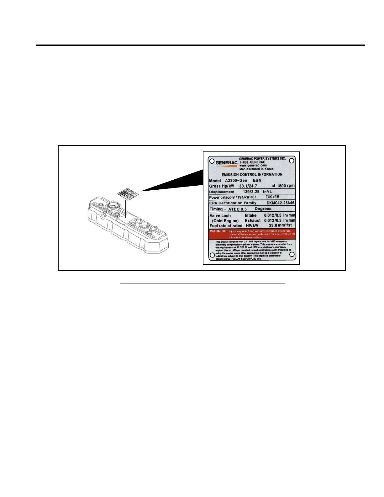
A data plate is riveted to the cylinder head cover to verify compliance with EPA emissions regulations.
Cylinder Head Cover
Figure 2-1. Emissions Data Plate (Sample)
Owner’s Manual for Stationary Diesel Generators 5
Page 12
Specifications
2.2 — Specifications
2.2.1— Engine
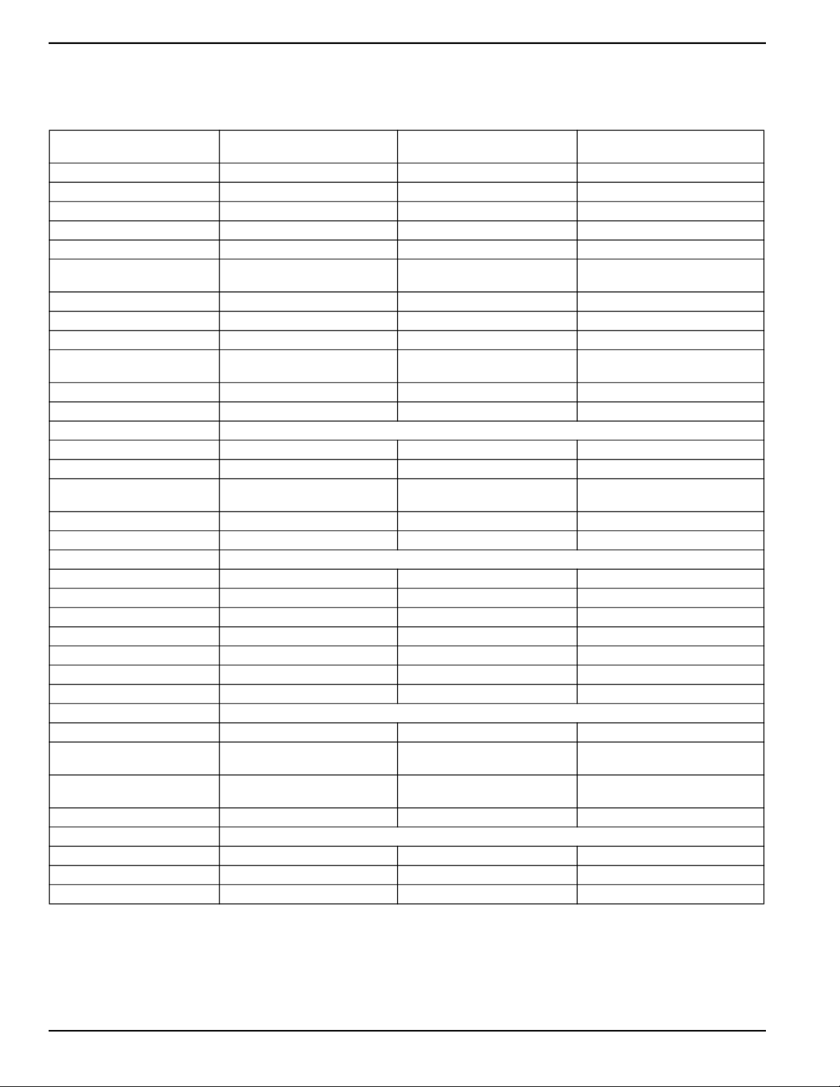
General A2300-Gen
15 & 20 kW
Engine Manufacturer GENERAC GENERAC GENERAC
Type 4 cylinder, in-line, 4 cycle 4 cylinder, in-line, 4 cycle 4 cylinder, in-line, 4 cycle
Horse Power 33 Hp @ 1,800 rpm 49 Hp @ 1,800 rpm 85 Hp @ 1,800 rpm
Fuel Type Ultra Low Sulfur Diesel Ultra Low Sulfur Diesel Ultra Low Sulfur Diesel
Fuel Filtering 5 Microns 5 Microns 10 Microns
Bore and Stroke
Displacement 139.3 cubic inches (2.28 liter) 146 cubic inches (2.392 liter) 208.3 cubic inches (3.41 liter)
Firing Order 1-3-4-2 1-3-4-2 1-3-4-2
Direction or Rotation CCW - As Viewed From Flywheel CCW - As Viewed From Flywheel CCW - As Viewed From Flywheel
Dimensions L x W x H
Dry Weight 441 lbs (200 kgs) 573 lbs (260 kgs) 551 lbs (250 kgs)
Compression Ratio 21.3 : 1 21.3 : 1 18.5 : 1
Cooling System
Water Pump Pre-Lubed, Self-Sealing Pre-Lubed, Self-Sealing Pre-Lubed, Self-Sealing
Drive Belt Belt Belt
Thermostat
System Coolant Capacity 2.8 gal (10.6 liter) 2.8 gal (10.6 liter) 2.8 gal (10.6 liter)
Coolant Flow Rate 10 gal (38 liter)/min at 1800 RPM 10 gal (38 liter)/min at 1800 RPM 12.2 gal (46 liter)/min at 1800 RPM
Lubricating System
Oil Pump Type Gear Gear Gear
Oil Filter Type Full Flow Spin-On Canister Full Flow Spin-On Canister Full Flow Spin-On Canister
Oil Cooler Installed Installed Installed
Crankcase Capacity 6.87 qt. (6.5 liter) 6.8 qt. (6.4 liter) 7.4 qt. (7.0 liter)
Lubricating Oil 15W-40 15W-40 15W-40
Oil Fill Location Filler Cap on Valve Cover Filler Cap on Valve Cover Filler Cap on Valve Cover
Oil Drain Location Oil Pan, Bottom Side Oil Pan, Bottom Side Oil Pan, Front
Intake and Exhaust System
Intake Air System Naturally Aspirated Turbocharged Turbocharged/Aftercooled
Maximum Allowable
Intake Restriction
Maximum Allowable
Exhaust Back Pressure
Breather Closed Crankcase System Open Crankcase System Open Crankcase System
Other Specifications
Unbalanced Load Capabilities 25% 25% 25%
Power De-Rate 1.7% for Every 5° Above 77° F 1.7% for Every 5° Above 77° F 1.7% for Every 5° Above 77° F
Operating Temperature Range -20° F to 120° F -20° F to 120° F -20° F to 120° F
3.46 in x 3.70 in
(88 mm x 94 mm)
685 x 491 x 636 mm
(26.97 in x 19.33 in x 25.04 in)
Full Open Temperature:
185° F (85° C)
25 in. of Water (6.23 kPa) 25 in. of Water (6.23 kPa) 25 in. of Water (6.23 kPa)
23.6 in. of Water (5.88 kPa) 23.6 in. of Water (5.88 kPa) 24 in of Water (5.98 kPa)
3.54 in x 3.70 in
(90 mm x 94 mm)
677.1 x 497.8 x 721.3 mm
(26.66 in x 19.60 in x 28.40 in)
Full Open Temperature:
203° F (95° C)
A2400T-Gen
30 kW
A3400T-Gen
48/50 kW
3.86 in x 4.45 in
(98 mm x 113 mm)
742 x 587 x 721 mm
(29.21 in x 23.11 in x 28.39 in)
Full Open Temperature:
194° F (90° C)
A complete specification sheet is included in the documentation provided with the unit at the time of purchase. For
additional copies, consult your local Authorized Service Dealer.
6 Owner’s Manual for Stationary Diesel Generators
Page 13
Specifications
2.3 — Engine Oil Recommendations
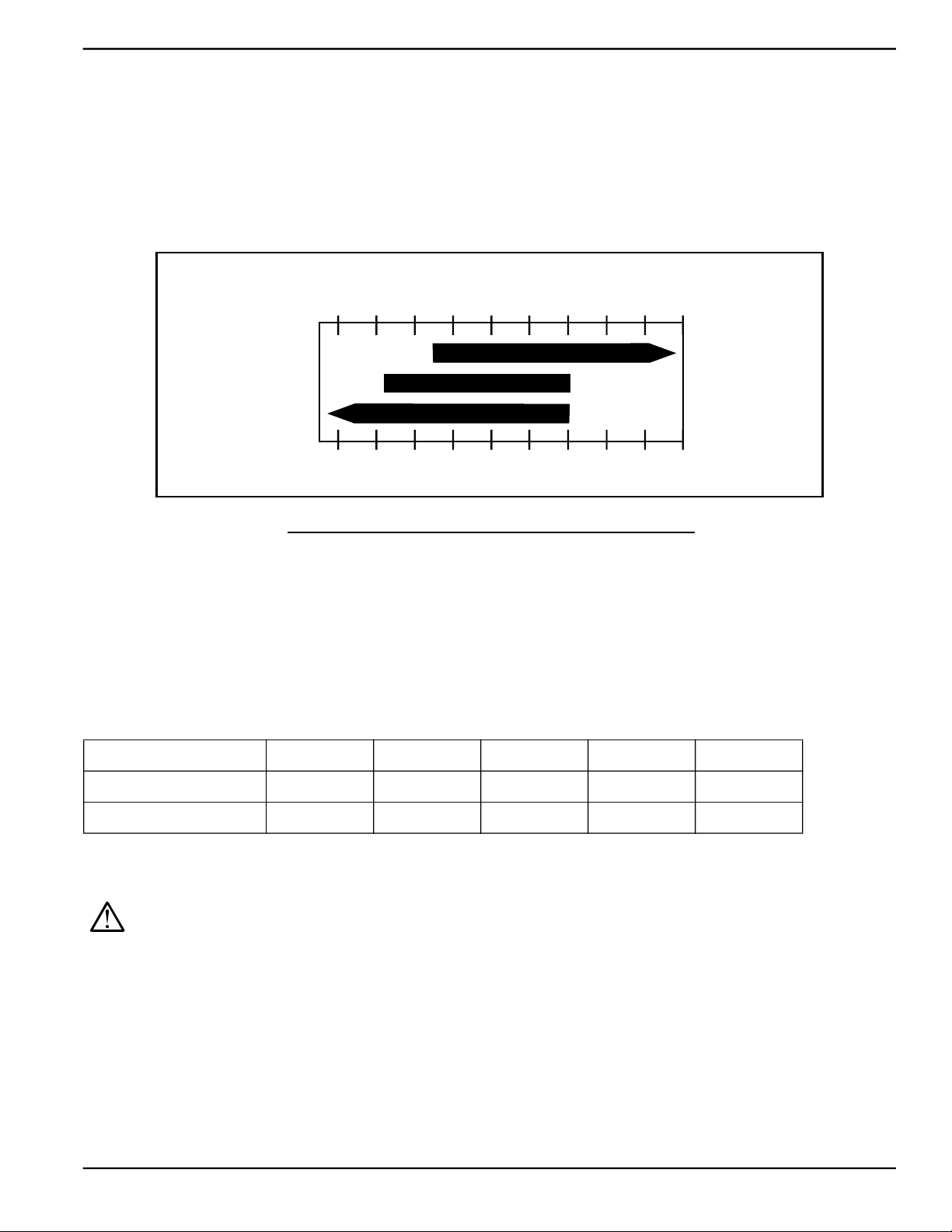
To maintain the product warranty, use only genuine Generac replacement parts. Generac oil kits include both the oil filter and air filter, and can be obtained through any Authorized Dealer.
All Generac oil kits meet minimum American Petroleum Institute (API) Service Class CD or better. Select the appropriate viscosity oil grade according to the expected operating temperature. Synthetic oil also can be used in the appropriate weight as standard. Once synthetic oil is used, it should be used for the life of the generator. It is not recommended
to go back to a mineral oil. Do not use special additives.
º C
º F
All Seasons
Winter Conditions
Arctic Conditions
º C
º F
- 40
- 40
- 40
- 40
- 30
- 22
- 30
- 22
- 20
- 10140
- 4
10W-30
5W-30
- 20
- 101403210502068308640
- 4
10502068308640
32
15W-40
10450122
10450122
Figure 2-2. Lubricating Oil Recommendations
2.4 — Coolant Water Treatment
Use of improper coolants can damage the engine cooling system. Use demineralized water or distilled water for best
results. Hard water causes scale deposits, which reduces cooling efficiency and raises internal temperatures, possibly
leading to engine damage. Use an anti-corrosive to prevent rot in summer and anti-freeze to prevent freezing in winter.
Dilute the anti-freeze based on a theoretical temperature that is 9-18°F (5-10°C) below the lowest temperature
expected in the area. A ratio of 40-60% is most common.
Freezing Point °F (°C) 3 (-16) -13 (-25) -31 (-35) -58 (-50) -54 (-48)
Coolant (% Volume) 30 40 50 60 70
Water (% Volume) 70 60 50 40 30
NOTE: Use only Peak Fleet-Charge® 50/50 ethylene glycol type coolant (available from any authorized
Generac dealer).
CAUTION: Do not use propylene glycol type coolant. Using the wrong coolant, mixing different types
of coolant, or even mixing different brands of the correct type of coolant, can produce unsatisfactory
results, possibly leading to engine damage.
Owner’s Manual for Stationary Diesel Generators 7
Page 14
Specifications
2.5 — Fuel Requirements
IMPORTANT! DO NOT use Home Heating Oil or Bio-Diesel Fuel.
Use No.1D diesel fuel when temperatures are below freezing. Use No. 2D diesel fuel when temperatures are above
freezing. Starting October 1, 2010, diesel fuel must also meet the following requirements:
• Sulfur content of 15 parts per million (ppm) maximum.
• Maximum Cetane index of 40 or a maximum aromatic content of 35 volume percent.
Allow at least 5 percent of the tank capacity for fuel expansion. DO NOT OVERFILL!
2.5.1— Fuel Maintenance
Always treat diesel fuel for long term storage. Use the approved fuel additive and water abatement material. Test
stored fuel every 90 days and provide additional treatment if required. Periodically check and dry abatement material
as necessary.
2.6 — Battery Requirements
Group 27F, 12 Volt For areas where temperatures do not regularly drop below 32° F (0° C).
NOTE: Battery dimensions (L x W x H) for Group 27F battery must not exceed 12-1/2" x 6-13/16" x 8-15/16"
(318 mm x 173 mm x 227 mm).
Group 31, 12 Volt For areas where temperatures regularly drop below 32° F (0° C).
NOTE: Battery dimensions (L x W x H) for Group 31 battery must not exceed 13" x 6-13/16" x 9-7/16"
(330 mm x 173 mm x 240 mm).
2.6.1— Battery Charger
The battery charger is integrated into the control panel module. It operates as a “Smart Charger” which ensures output
charging levels are safe and continuously optimized to promote maximum battery life.
2.7 — Corrosion Protection
Periodically wash and wax the enclosure using automotive type products. Frequent washing is recommended in salt
water/coastal areas.
2.8 — Accessories
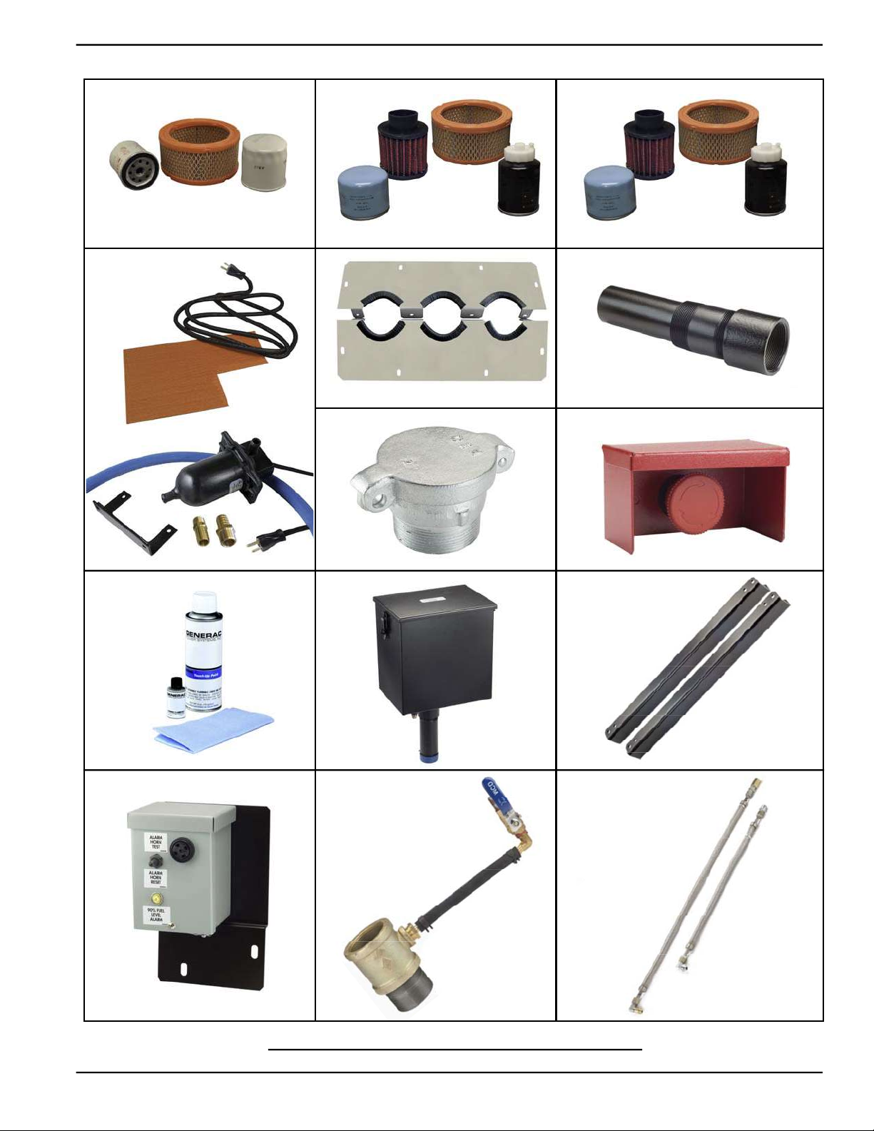
The following product accessories are available. Contact a Dealer for additional information.
1. Scheduled Maintenance Kit (Part No. 006572-0; 15/20 kW) 8. Emergency Stop Switch (Part No. 006510-0)
2. Scheduled Maintenance Kit (Part No. 006571-0; 30 kW) 9. Touch-Up Paint Kit (Part No. 005704-0)
3. Scheduled Maintenance Kit (Part No. 006570-0; 50 kW) 10. Five Gallon Spill Box (Part No. 006502-0)
4. Cold Weather Kit (Part No. 006560-0: 15/20 kW; Part No.
006559-0: 30 kW; Part No. 006558-0: 50 kW)
5. Vent Extension Support Kit (Part No. 006588-0) 12. 90% Fuel Fill Level Alarm (Part No. 006504-0)
6. Fuel Fill Drop Tube (Part No. 006507-0) 13. Spill Box Drain Back (Part No. 006511-0)
7. Lockable Fuel Fill Cap (Part No. 006512-0) 14. Stainless Steel Fuel Lines (Part No. 006513-0:15/20 kW;
8 Owner’s Manual for Stationary Diesel Generators
11. Fuel Tank Risers (Part No. 006505-0: 15/20 kW; Part
No. 006506-0: 30/50 kW)
Part No. 006517-0: 30 kW; Part No. 006516-0:
50 kW)
Page 15
Specifications
1. 2.
4.
5.
7. 8.
3.
6.
9. 10.
12. 13. 14.
11.
Figure 2-3. Product Accessories
Owner’s Manual for Stationary Diesel Generators 9
Page 16

Specifications
This page intentionally left blank.
10 Owner’s Manual for Stationary Diesel Generators
Page 17
Section 3 Activation and Startup
IMPORTANT NOTE: The unit fuel tank has been inspected by AHJ (authority having local jurisdiction) or fire
marshal and meets all requirements. Unit is fueled and the fuel is treated as per additive directions.
3.1 — Orientation
NOTE: The 3.4L engine is depicted in the artwork used in this manual. The location and appearance of some
components may vary between engine models.
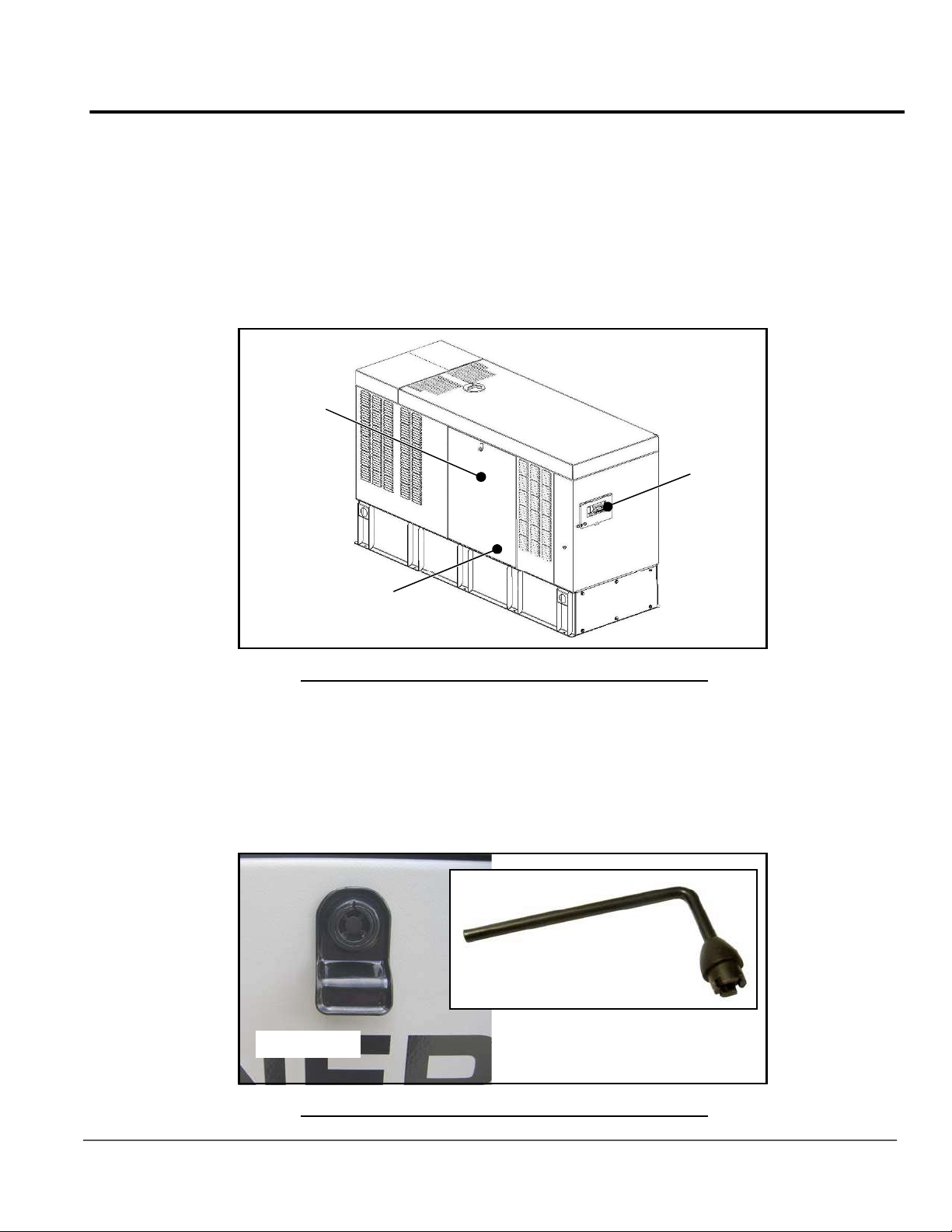
The side of the enclosure with the viewing window is identified as the rear of the generator set. The right and left sides
are identified by standing at the rear and looking towards the front of the unit.
Fuel Priming
Pump
Viewing
Window
Battery
Figure 3-1. Enclosure (Rear Left View)
3.2 — Remove Side Access Panels
NOTE: Access panels are located at both the front and sides of the enclosure.
1. Insert key into latch and rotate counterclockwise 1/2 turn. See Figure 3-2.
2. Raise panel using thumb latch.
Key
Thumb Latch
Figure 3-2. Access Panel Key
Owner’s Manual for Stationary Diesel Generators 11
Page 18
Activation and Startup
3.3 — Prime Fuel System
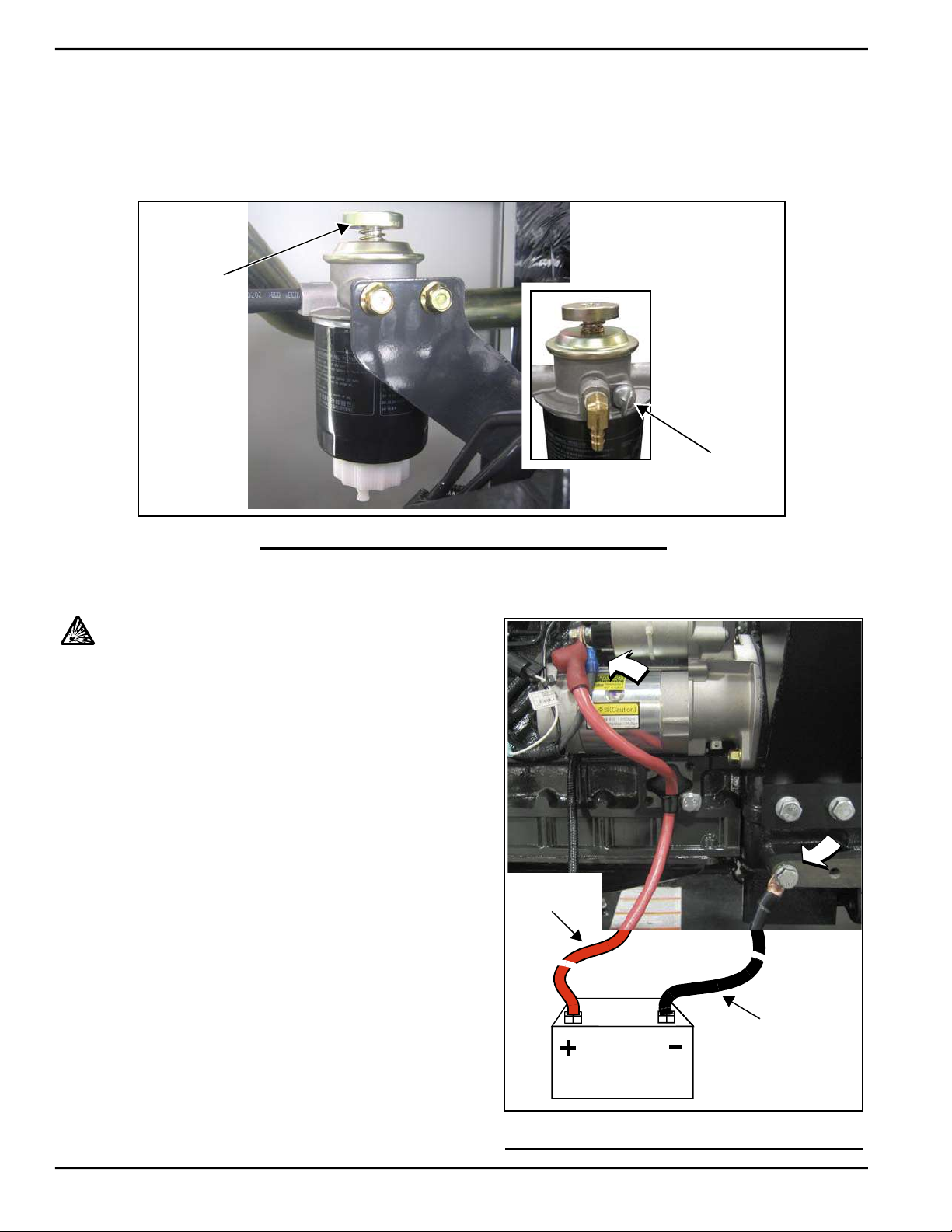
1. See Figure 3-3. Loosen the air bleed screw and work priming pump until bubbles are observed. Place a shop rag
around the air bleed screw to catch any loss of fuel.
2. When all bubbles are purged and replaced by a solid stream of fuel, tighten the air bleed screw.
3. Check for leaks.
Priming
Pump
Air Bleed
Screw
Figure 3-3. Prime Fuel System
3.4 — Install Battery
CAUTION: Always connect the positive battery
cable first. If the positive cable should contact
ground with the negative cable installed, the resulting sparks may cause a battery explosion which
could result in serious injury.
2.4L/3.4L Models
NOTE: For 2.3L units, see special instructions under Subsec-
tion 5.7.7.
1. Loosen two screws with nylon washers to release hold-
down clamp from battery tray.
2. Install battery onto tray.
3. Install two screws with nylon washers to secure hold-
down clamp to battery tray.
4. Install battery positive cable (red) to battery positive (+)
terminal.
5. Install battery negative cable (black) to battery negative
(-) terminal.
Red Lead
From Starter
Black Lead
To Fra m e
Battery
Figure 3-4. Battery Cable Connections
12 Owner’s Manual for Stationary Diesel Generators
Page 19
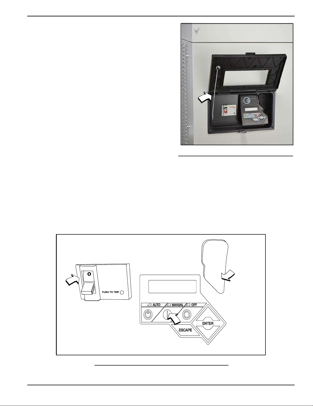
3.5 — Open Viewing Window
1. Rotate viewing window upward to access control panel.
2. To hold viewing window in the open position, remove rod
from clip at back of window and insert into hole in frame.
See Figure 3-5.
Activation and Startup
Figure 3-5. Viewing Window
3.6 — Start and Run Engine
1. Pull up rubber flap covering fuse holder and verify installation of 7.5 amp fuse. See A of Figure 3-6.
2. Move the Main Circuit Breaker switch down to the OFF (Open) position. See B of Figure 3-6.
3. Press the MANUAL key on the control panel keypad to start the engine. The blue LED above the key illuminates
to confirm that the system is in the MANUAL mode. See C of Figure 3-6.
4. Allow the engine to run until it reaches normal operating temperature.
5. Press the OFF key on the control panel keypad to stop the engine.
7.5 Amp Fuse
and USB Port
A
B
OFF
Main Circuit Breaker
LCD and Keypad
C
Figure 3-6. Generator Control Panel
Owner’s Manual for Stationary Diesel Generators 13
Page 20
Activation and Startup
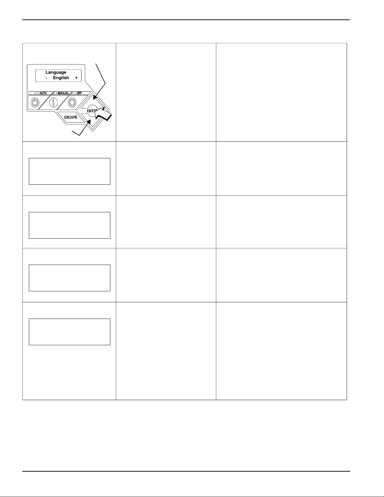
3.7 — Activate Unit
Display Reads:
Up Arrow = (+)
Down Arrow = (-)
Display Reads:
Activate me (ENT) or
ESC to run in manual
Display Reads:
To Activate go to
www.activategen.com
Generator Active is displayed on the
LCD screen when the unit is first
powered up. After displaying firmware
and hardware version codes, as well as
other system information, the Installation
Wizard is launched, and the Language
screen is displayed.
Use the ARROW keys to scroll to desired
language.
Press ENTER.
Press ENTER. Press the ESCAPE key to abort the activation
Go to www.activategen.com or call 1888-9ACTIVATE (922-8482, US & CA
only) if activation passcode is not available.
If activation pass code is available, wait a
few seconds for the next display.
If the wrong language is selected, it may be changed
later using the Edit menu.
sequence. NOT ACTIVATED is displayed and the
generator will run in manual mode only. Disconnect and
reconnect the negative battery cable to restart the
activation routine. If power is removed after a
successful activation, no data is lost, but the time and
date must be updated.
Display Reads:
SN 1234567890
PASS CODE XXXXX
Display Reads:
Select Hour (0-23)
- 6 +
Use ARROW keys to increment or
decrement the digit to correspond to the
first number of the pass code.
Press ENTER.
Repeat step to enter remaining digits.
Use ARROW keys to increment or
decrement the hour. Press ENTER.
Use ARROW keys to increment or
decrement the minute. Press ENTER.
Use ARROW keys to select the month.
Press ENTER.
Use ARROW keys to increment or
decrement the date. Press ENTER.
Use ARROW keys to increment or
decrement the year. Press ENTER.
Press the ESCAPE to return to preceding digits if a
correction becomes necessary.
If attempts to enter the activation code are
unsuccessful, check the number against the code
given on activategen.com. If it is correct, contact 1-8889ACTIVATE (922-8482, US & CA only).
14 Owner’s Manual for Stationary Diesel Generators
Page 21
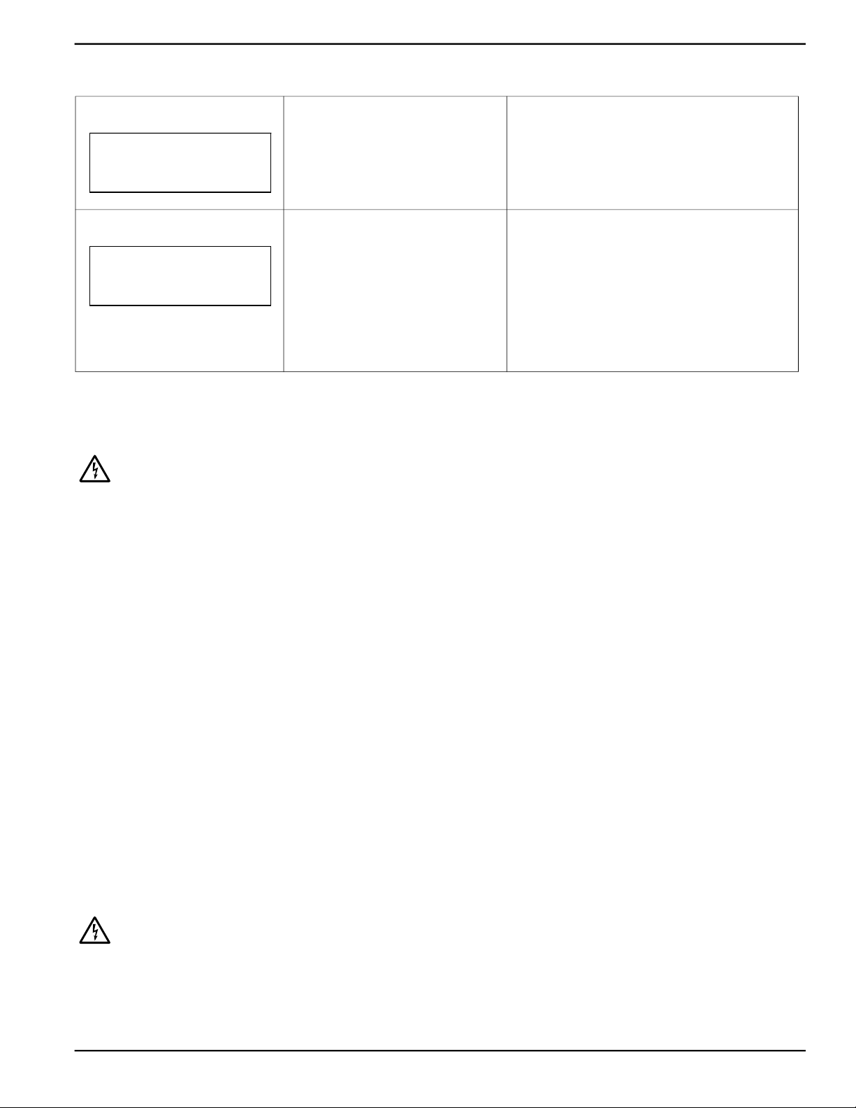
Activation and Startup
Display Reads:
Quite Test Mode?
Yes No
Display Reads:
Select Hour (0-23)
Use ARROW keys to select either Yes or
No.
Press ENTER.
Set Exercise Time.
Use ARROW keys to increment or
decrement the hour. Press ENTER.
- 1 +
Use ARROW keys to increment or
decrement the minute. Press ENTER.
Use ARROW keys to scroll to the day of
the week. Press ENTER.
3.8 — Operational Checks
CAUTION: The following procedures require special tools and skills. Contact a Generac Dealer or an
authorized service provider to perform these tasks.
3.8.1— Self Test
Select YES to perform exercise at low speed. Select
NO to perform exercise at normal operating speed.
In the AUTO mode, the engine starts and runs once
each week at the time and day specified. During the
exercise cycle, the unit runs approximately 12 minutes
and then shuts down. Transfer of loads to the generator
does not occur unless utility power fails.
Upon power up, the controller goes through a system self test which checks for the presence of utility voltage on the
DC circuits. This is done to prevent damage if the installer mistakenly connects AC utility power sense wires into the
DC terminal block. If utility voltage is detected, the controller displays a warning message and locks out the generator,
thereby preventing damage to the controller. Remove power to the controller to clear this warning.
Utility voltage must be turned on and present at the N1 and N2 terminals inside the generator control panel for this test
to be performed and pass.
Before starting, complete the following:
1. Verify that the generator is OFF. The red LED above the OFF key on the control panel keypad illuminates to con-
firm that the system is in the OFF mode.
2. Verify that the Main Circuit Breaker switch on the generator control panel is in the OFF (Open) position.
3. Turn off all circuit breakers/electrical loads that will be powered by the generator.
4. Check the fuel level, coolant level, and engine lubricating oil level. See Subsections 5.7.2, 5.7.4, and 5.7.6,
respectively.
During initial start up only, the generator may exceed the normal number of start attempts and experience an “over
crank” fault. This is due to accumulated air in the fuel system during installation. Reset the control board and restart up
to two more times, if necessary. If unit fails to start, contact the local dealer for assistance.
3.8.2— Check Manual Transfer Switch Operation
Refer to the manufacturer’s instructions.
CAUTION: Do not attempt manual transfer switch operation until all power voltage supplies to the
transfer switch have been positively turned off. Failure to turn off all power voltage supplies will result
in extremely hazardous and possibly fatal electrical shock.
Owner’s Manual for Stationary Diesel Generators 15
Page 22
Activation and Startup
3.8.3— Electrical Checks
Complete electrical checks as follows:
1. Verify that the generator is OFF. The red LED above the OFF key on the control panel keypad illuminates to con-
firm that the system is in the OFF mode.
2. Verify that the Main Circuit Breaker switch on the generator control panel is in the OFF (Open) position.
3. Turn OFF all circuit breakers/electrical loads that will be powered by the generator.
4. Turn on the utility power supply to the transfer switch using the means provided (such as a utility main line circuit
breaker).
CAUTION: The transfer switch is now electrically “hot.” Contact with “hot” parts will result in extremely
hazardous and possibly fatal electrical shock.
5. Use an accurate AC voltmeter to check utility power source voltage across transfer switch terminals N1, N2, and
N3 (if three phase). Normal line-to-line voltage should be equivalent to rated unit voltage.
6. Check utility power source voltage across terminals N1, N2, and N3 (if three phase) and the transfer switch neu-
tral lug.
7. When certain that utility supply voltage is compatible with transfer switch and load circuit ratings, turn OFF the
utility power supply to the transfer switch.
8. Press the MANUAL key on the control panel keypad to crank and start the engine.
9. Allow the engine to warm up for about five minutes. Flip the Main Circuit Breaker switch on the generator control
panel up to the ON (or closed) position.
CAUTION: Generator power voltage is now supplied to the transfer switch. Contact with live transfer
switch parts will result in dangerous and possibly fatal electrical shock.
10. Connect an accurate AC voltmeter and a frequency meter across transfer switch terminal lugs E1, E2, and E3 (if
three phase).
11. Successively connect the AC voltmeter test leads across terminal lugs E1, E2, and E3 (if three phase) and neu-
tral; then across E2 and neutral. Voltage reading in each case should match utility voltage reading. If system is
three phase, verify that generator phase rotation matches utility phase rotation.
12. Move the Main Circuit Breaker switch on the generator control panel down to the OFF (Open) position.
13. Press the OFF key on the control panel keypad to shut the engine down.
CAUTION: Do not proceed unless certain that generator AC voltage and frequency are correct and
within the stated limits.
3.8.4— Test Generator Under Load
To test the generator set with electrical loads applied, proceed as follows:
1. Verify that the generator is OFF. The red LED above the OFF key on the control panel keypad illuminates to con-
firm that the system is in the OFF mode.
2. Turn OFF all breakers/electrical loads that will be powered by the generator.
3. Turn OFF the utility power supply to the transfer switch, using the means provided (such as a utility main line cir-
cuit breaker).
CAUTION: Do not attempt manual transfer switch operation until all power voltage supplies to the
transfer switch have been positively turned off. Failure to turn off all power voltage supplies will result
in extremely hazardous and possibly fatal electrical shock.
4. Manually set the transfer switch to the STANDBY position, i.e., load terminals connected to the generator’s E1,
E2, and E3 (if three phase) terminals.
5. Press the MANUAL key on the control panel keypad. The engine should crank and start immediately.
6. Allow the engine to warm up for a few minutes.
16 Owner’s Manual for Stationary Diesel Generators
Page 23
Activation and Startup
7. Move the Main Circuit Breaker switch on the generator control panel up to the ON (or closed) position. The
switch is now powered by the standby generator.
8. Turn ON the circuit breaker/electrical loads powered by the generator.
9. Connect a calibrated AC voltmeter and a frequency meter across terminal lugs E1, E2, and E3 (if three phase).
Voltage should be approximately unit rated voltage. Check with clamp on amp meter to ensure unit is not overloaded.
10. Let the generator run at full rated load for 20-30 minutes. Listen for unusual noises, vibration or other indications
of abnormal operation. Check for oil leaks, evidence of overheating, etc.
11. When testing under load is complete, turn OFF electrical loads.
12. Move the Main Circuit Breaker switch on the generator control panel up to the OFF (or open) position.
13. Allow the engine to run at no-load for 2-5 minutes.
14. Press the OFF key on the control panel keypad to shut the engine down.
3.8.5— Check Automatic Operation
To check the system for proper automatic operation, proceed as follows:
1. Verify that the generator is OFF. The red LED above the OFF key on the control panel keypad illuminates to con-
firm that the system is in the OFF mode.
2. Install front cover of the transfer switch.
3. Turn ON the utility power supply to the transfer switch, using the means provided (such as a utility main line cir-
cuit breaker).
NOTE: Transfer Switch will transfer back to utility position.
4. Move the Main Circuit Breaker switch on the generator control panel up to the ON (or closed) position.
5. Press the AUTO key on the control panel keypad. The system is now ready for automatic operation.
6. Turn OFF the utility power supply to the transfer switch.
With the generator ready for automatic operation, the engine will crank and start when the utility source power is turned
OFF after a 10 second delay (factory default setting). After starting, the transfer switch connects load circuits to the
standby side. Let the system operate through its entire automatic sequence of operation.
With the generator running and loads powered by generator
AC output, turn ON the utility power supply to the transfer
switch. The system transfers back to the utility position and
then runs through the cool down cycle and shuts down.
3.9 — Final Instructions
1. Use key to install side access panels.
2. Close viewing window.
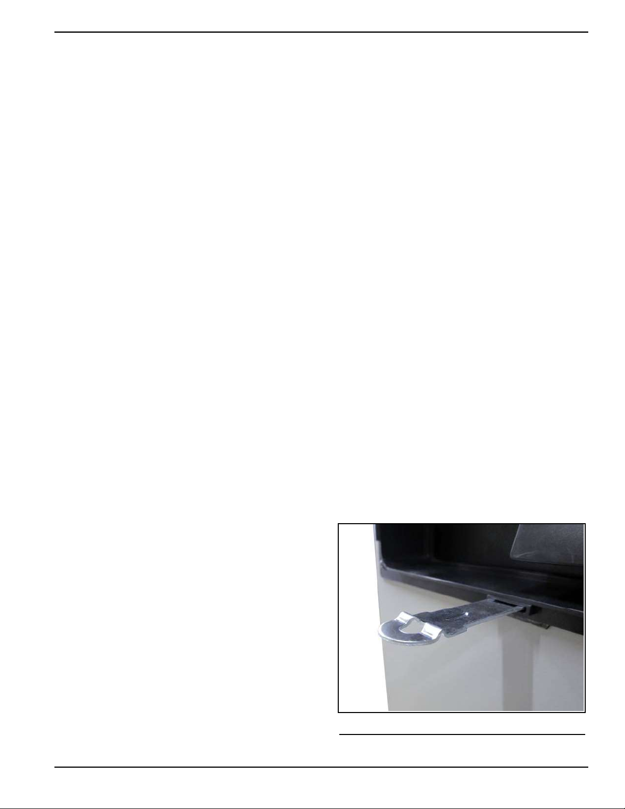
NOTE: Obtain viewing window hasp, if not installed. See
Figure 3-7. With the retaining tab at the bottom, insert
square end of hasp into slot below viewing window. Push on
hasp until it snaps in place. Gently pull on hasp to verify that
it will not come free.
3. Install customer supplied padlock into hasp.
Figure 3-7. Install Viewing Window Hasp
Owner’s Manual for Stationary Diesel Generators 17
Page 24

Activation and Startup
This page intentionally left blank.
18 Owner’s Manual for Stationary Diesel Generators
Page 25
Section 4 Operation
4.1 — Control Panel
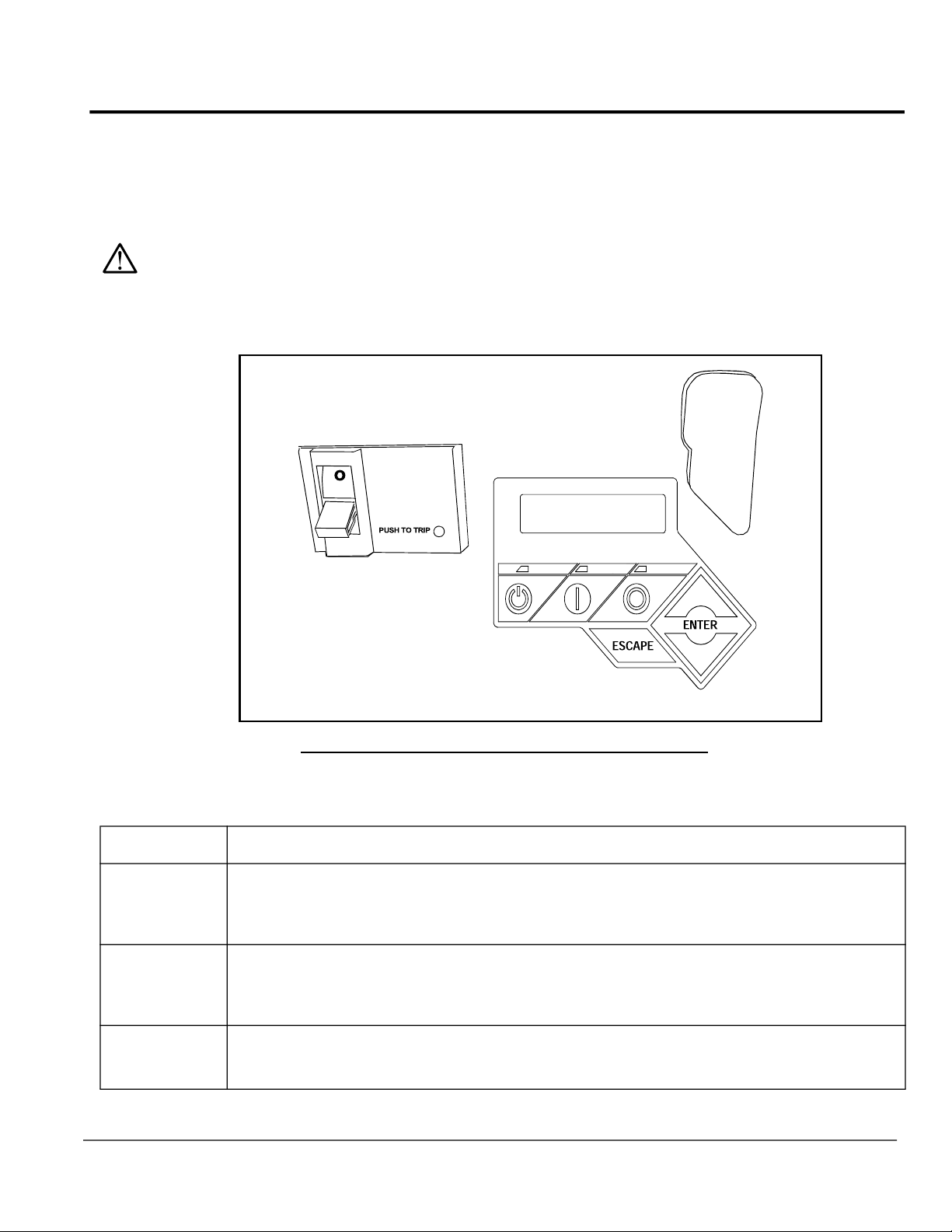
NOTE: The control panel is intended for use by qualified service personnel only.
The control panel is located behind the viewing window at the rear of the unit.
With the control panel set to AUTO, the engine may crank and start at any time without warning. Such
automatic starting occurs during the programmed exercise cycle or when utility power source voltage
drops below the configured level. To prevent possible injury that might occur during sudden starts,
always set the control panel to OFF and remove the control panel fuse before working on or around the
generator or transfer switch. For added security, place a DO NOT OPERATE tag or placard on both the
control panel and transfer switch.
7.5 Amp Fuse
and USB Port
OFF
Main Circuit Breaker
LCD Screen and Keypad
Figure 4-1. Generator Control Panel
4.2 — Auto/Manual/Off Keypad
Feature Description
Press key to activate fully automatic operation. Green LED above key illuminates to confirm that system is
AUTO
MANUAL
in AUTO mode.
Transfer to standby power occurs if utility power fails.
Functionality of exercise timer is enabled, if set.
Press key to crank and start engine. Blue LED above key illuminates to confirm that system is in MANUAL
mode.
Transfer to standby power occurs if utility power fails.
Functionality of exercise timer is disabled.
%983 1%29%0 3**
Press key to shut down engine, if running. Red LED above key illuminates to confirm that system is in OFF
OFF
Owner’s Manual for Stationary Diesel Generators 19
mode.
Transfer to standby power does not occur if utility power fails.
Page 26
Operation
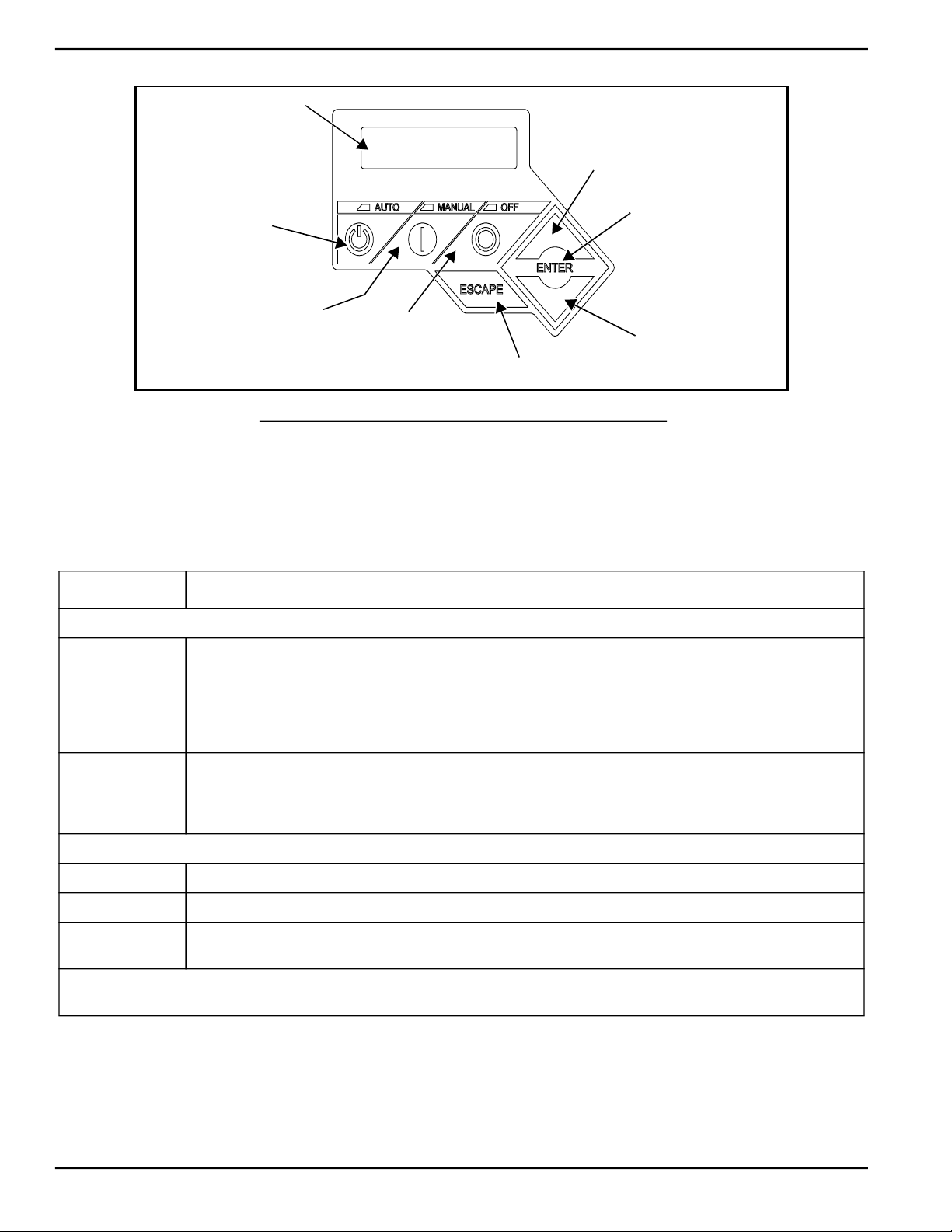
LCD Screen
Up Arrow Key
Auto Key
Manual Key
OFF Key
Escape Key
Figure 4-2. Control Panel Keypad and LCD Screen
4.3 — LCD Screen and Navigation Keypad
See Figure 4-3.
Feature Description
System Menus
The system returns to the Home screen if no key is pressed within five minutes. The screen normally displays a Status message, such as Ready to Run (Auto mode) or Switched to OFF (Off mode), and the total
HOME Screen
Hours of Protection. If an active alarm/warning condition occurs, the associated Alarm/Warning message is
displayed. To clear the Alarm/Warning message, press OFF on the control panel keypad followed by the
ENTER key. In the event of multiple Alarms/Warnings, the next message is then displayed. The highest priority alarm is always displayed first.
Enter Key
Down Arrow Key
Enables the operator to navigate the software using the Up Arrow, Down Arrow, Enter and Escape keys.
MAIN MENU
Escape Key Used to abort a routine or back up to the preceding menu.
Enter Key Used to make a selection or save an entry.
Arrow Keys
NOTE: Pressing any key illuminates the backlight for 30 seconds. The backlight also illuminates for 30 seconds whenever an
active Alarm/Warning message is displayed.
20 Owner’s Manual for Stationary Diesel Generators
The Main Menu can be accessed from any sub menu by consecutively pressing the Escape key. Each time
the Escape key is pressed, the preceding menu is displayed. The Main Menu is reached when the System,
Date/Time, Battery, and Sub Menus are displayed.
Navigation Keys
Used to move forward or backward from menu to menu or to scroll forward or backward (increment or decrement) through available selections.
Page 27
Operation
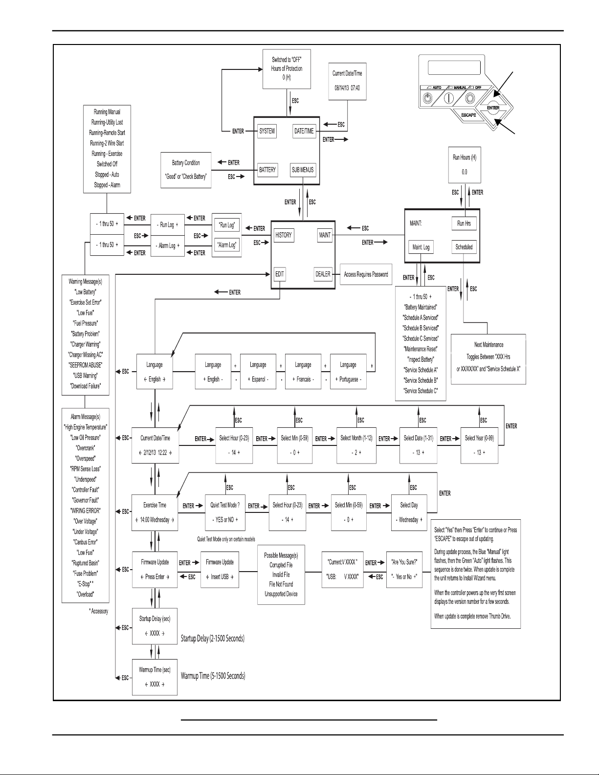
Home Screen
Up Arrow = (+)
Down Arrow = (-)
Main Menu
Figure 4-3. Navigation Menu
Owner’s Manual for Stationary Diesel Generators 21
Page 28

Operation
4.4 — Alarm/Warning Conditions
The owner/operator is alerted to Alarm and/or Warning conditions via the control panel LCD screen. All Alarm conditions cause the generator to shut down. The Warning messages alert the operator to conditions that do not disable the
unit or require immediate correction.
The possible Alarm/Warning messages are listed below.
Alarm Messages Warning Messages
• High Engine Temperature • Low Battery
• Low Oil Pressure • Exercise Set Error
• Overcrank • Low Fuel
• Overspeed • Fuel Pressure
• RPM Sense Loss • Battery Problem
• Underspeed • Charger Warning
• Controller Fault • Charger Missing AC
• Governor Fault • SEEPROM ABUSE
• WIRING ERROR • USB Warning
• Over Voltage • Download Failure
• Under Voltage
• Canbus Error
• Low Fuel
• Ruptured Basin
• Fuse Problem
• Overload
NOTE: Unless properly trained to correct and clear Alarm/Warning conditions, contact an Authorized Dealer or trained
service technician.
4.5 — Change Time and Date
To change the time and date after activation, see the Navigation Menu in Figure 4-3. If power is lost (battery is disconnected/reconnected, control panel fuse is removed/installed, etc.), the display automatically prompts the user for the
Time and Date. All other information is retained in memory.
4.6 — Programmable Timers
4.6.1— Dealer Programmable
4.6.1.1—Exercise Time
A programmable exercise time is provided. In the AUTO mode, the engine starts and runs once each week at the time
and day specified. During the exercise cycle, the unit runs approximately 12 minutes and then shuts down. Transfer of
loads to the generator does not occur unless utility power fails.
NOTE: A Dealer password is required to change the Exercise time.
22 Owner’s Manual for Stationary Diesel Generators
Page 29

Operation
4.6.2— User Programmable
4.6.2.1—Start-Up Delay Timer
A programmable line interrupt delay (or Start-Up Delay) timer is provided. When utility voltage fails (falls below 60% of
nominal), the start-up delay timer is started. If the voltage rises above the Utility Volts Low threshold, the timer is reset.
If the utility voltage remains below the threshold during the duration of the timer, the unit cranks and starts.
NOTE: The factory default setting is five seconds, but is adjustable from 2 to 1500 seconds.
4.6.2.2—Warm-Up Delay Timer
A programmable Warm-Up Delay timer is provided. As soon as the generator starts, the warm-up timer is started.
When the warm-up timer expires, the control transfers load to the generator (through the transfer switch) if the utility
voltage is less than 80% of nominal. If utility voltage is greater than the threshold at expiration of the warm-up time, the
load is not transferred to the generator and a cool-down period begins. At the end of the cool-down period, the generator stops.
NOTE: The factory default setting is five seconds, but is adjustable from 5 to 1500 seconds.
4.7 — USB Port for Firmware Updates
A USB port is located beneath the rubber flap on the control panel, and is provided for firmware updates. Firmware
updates must be performed by an Authorized Service Dealer.
NOTE: The USB port is intended for use with a USB thumb drive only. The USB port is not intended for charging
devices such as phones or laptops. Do not connect any consumer electronics to the USB port.
4.8 — Battery Charger
NOTE: The battery charger is integrated into the control panel module.
The battery charger ensures:
• Output is continually optimized to promote maximum battery life.
• Charging levels are safe.
NOTE: A warning message is displayed on the LCD screen when the battery requires service.
4.9 — Transfer Switch Automatic Operation
In AUTO, the generator starts automatically when utility source voltage drops below the preset level. Once the unit
starts, loads are transferred to the standby power source.
To select automatic operation:
1. Verify that the transfer switch main contacts are set to the UTILITY position (loads connected to the utility power
source).
2. Verify that normal UTILITY power source voltage is available to transfer switch terminal lugs N1, N2 and N3 (if
three phase).
3. Move the Main Circuit Breaker switch on the control panel up to the ON (Closed) position.
4. Press the AUTO key on the control panel keypad. The green LED above the key illuminates to confirm that the
system is in the AUTO mode.
Owner’s Manual for Stationary Diesel Generators 23
Page 30

Operation
4.9.1— Automatic Sequence of Operation
4.9.1.1—Utility Failure
If the control panel keypad is set to AUTO when the utility power fails (falls below 60% of nominal, dealer programmable), a ten second Start-Up Delay timer is started (user programmable). If utility power is still absent when the time
expires, the engine cranks and starts.
Once started, a five second engine Warm-Up Delay timer starts (user programmable). When the time has elapsed, the
load is transferred to the generator. If utility power is restored (above 80% of nominal, dealer programmable) between
the time the engine is first started and expiration of the warm-up time, the controller completes the start cycle and then
runs through its normal cool-down cycle (while the load remains on the utility source throughout the episode).
4.9.1.2—Cranking
The cyclic cranking is controlled as follows:
Fifteen (15) seconds crank, seven (7) seconds rest, seven (7) seconds crank, seven (7) seconds rest; this sequence is
repeated for a total of six (6) crank cycles.
4.9.1.3—Load Transfer
With the generator running, the transfer of load is dependent upon the operating mode as follows:
• Starts and runs if utility power fails (falls below 60% of nominal) for five consecutive sec-
onds (adjustable).
• Starts a five second (adjustable) engine warm-up timer.
• Does not execute transfer if utility power returns before expiration of warm-up timer (but
finishes the warm-up and cool-down cycles).
• Transfers back to utility once utility power returns (above 80% of nominal) for fifteen
consecutive seconds.
AUTO
• Only shuts down if the OFF key is pressed or an alarm shutdown occurs.
• Once utility power returns, starts a cool-down cycle before it shuts down.
NOTE: Cool-down cycle is five minutes if turbocharger equipped, one minute if naturally
aspirated.
EXERCISE
• Only works in the AUTO mode.
• Does not exercise if generator is already running in AUTO.
• During exercise cycle, transfers only if utility power fails for ten consecutive seconds.
• Engine cranks and runs even if utility power is present, but does not transfer to generator.
• Transfers to generator if utility fails (falls below 60% of nominal) for ten consecutive sec-
MANUAL
onds.
• Transfers back to utility when utility returns for fifteen consecutive seconds. The engine
continues to run until the AUTO or OFF key is pressed.
4.10 — Transfer Switch Manual Operation
DO NOT attempt to activate the transfer switch manually until all power voltage supplies to
the switch have been completely turned off. Failure to turn off all power voltage supplies
may result in extremely hazardous and possibly fatal electrical shock.
Prior to automatic operation, manually exercise the transfer switch to verify that there is no binding or interference with
proper operation of the mechanism. Manual operation of the transfer switch is required if automatic operation fails.
24 Owner’s Manual for Stationary Diesel Generators
Page 31
Operation
IMPORTANT NOTE: Always use the applicable transfer switch owner's manual for actual manual transfer
switch operation instructions. The information presented here describes a typical V-style transfer switch,
which is not used for three phase applications.
4.10.1— Transfer to Generator Power
When utility power fails, manually transfer to standby power and start the generator as follows:
1. Press the OFF key on the control panel keypad.
2. Move the Main Circuit Breaker switch down to the OFF (Open) position.
3. Turn off the utility power supply to the transfer switch using the means provided (such as a utility main line circuit
breaker).
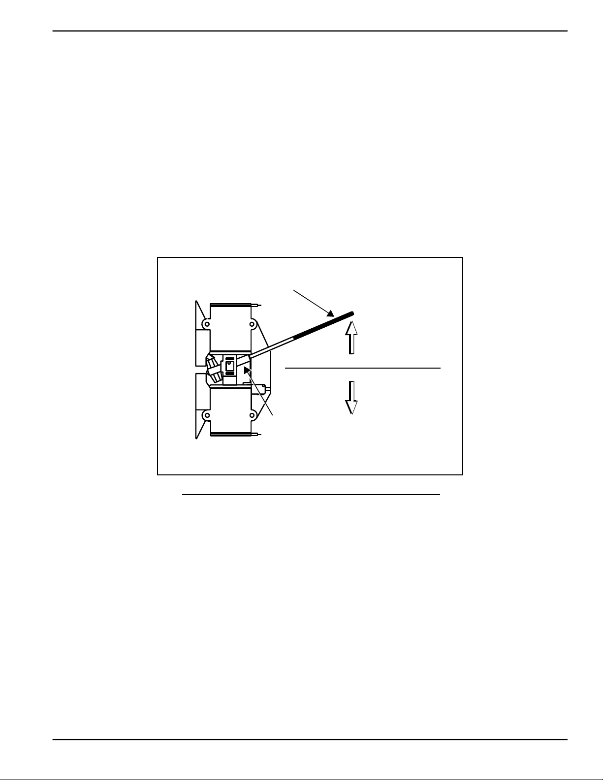
4. Use the manual transfer handle inside the transfer switch to move the main contacts to the STANDBY position
(loads connected to the standby power source).
5. Press the MANUAL key on the control panel keypad. The engine cranks and starts.
6. Allow the engine to run for two minutes to bring it up to normal operating temperature.
7. Move the Main Circuit Breaker switch up to the ON (Closed) position.
Manual Transfer
Handle
Load Connected to Utility
Load Connected to Standby
Transfer Switch
Operating Lever
NOTE: V-style transfer switch not used for three phase applications.
Figure 4-4. Manual Transfer Switch Operation (Typical)
4.10.2— Transfer Back to Utility Power
When utility power is restored, manually transfer back to utility power and shut down the generator as follows:
NOTE: Verify that utility voltage has returned and is at the proper value.
1. Move the Main Circuit Breaker switch down to the OFF (Open) position.
2. Allow the engine to run for two minutes at no-load to bring it up to normal operating temperature.
3. Press the OFF key on the control panel keypad to shut down the engine.
4. Verify that utility power supply to the transfer switch is turned off.
5. Use the manual transfer handle inside the transfer switch to move the main contacts to the UTILITY position
(loads connected to the utility power source).
6. Turn on the utility power supply to the transfer switch using the means provided.
7. Press the AUTO key on the control panel keypad. The green LED above the key illuminates to confirm that the
system is in the AUTO mode.
Owner’s Manual for Stationary Diesel Generators 25
Page 32

Operation
This page intentionally left blank.
26 Owner’s Manual for Stationary Diesel Generators
Page 33
Section 5 Maintenance
5.1 — Component Locations
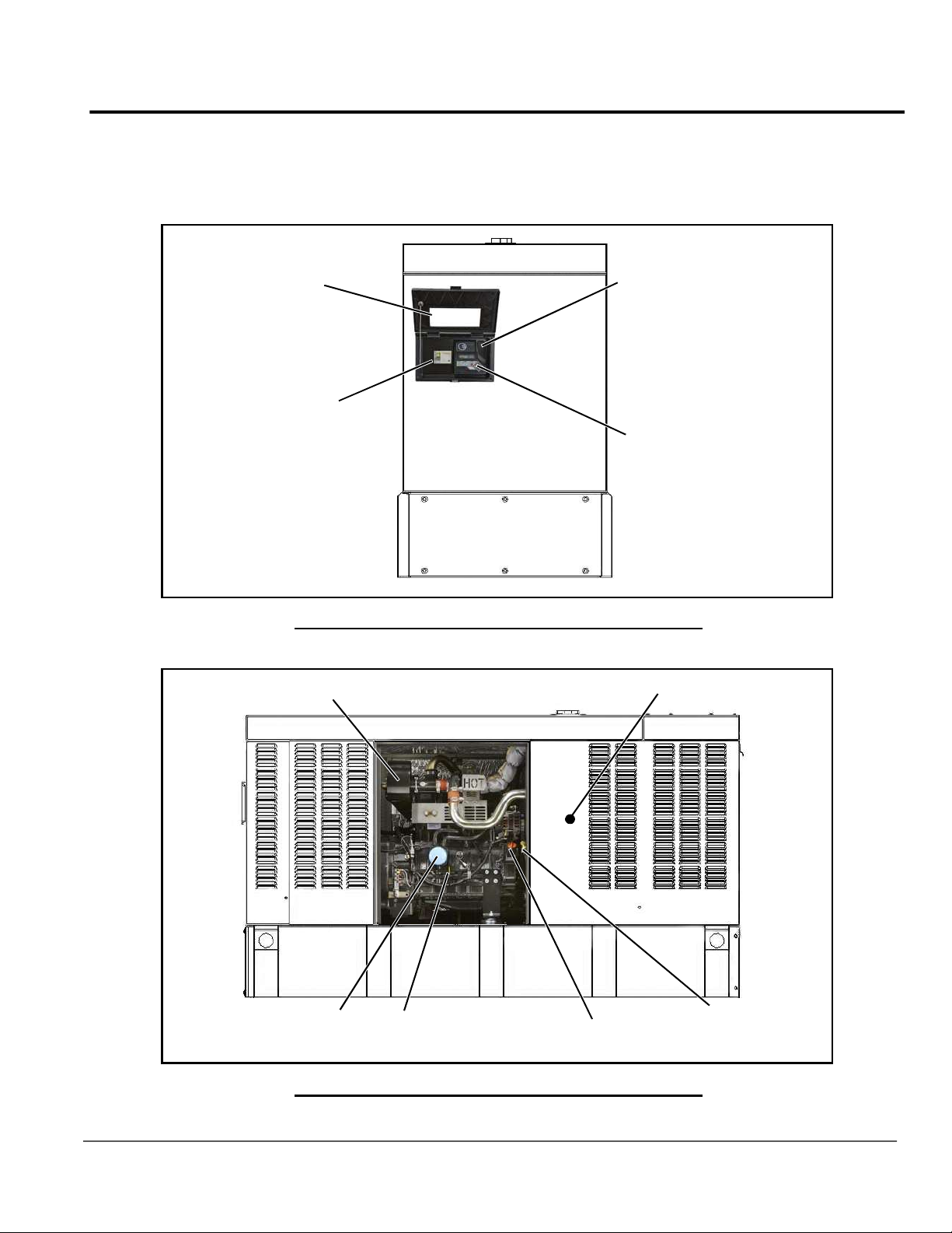
The side of the enclosure with the viewing window is identified as the rear of the generator set. The right and left sides
are identified by standing at the rear and looking towards the front of the unit.
Viewing
Window
Main Circuit Breaker
Air Filter
7.5 Amp Fuse
and USB Port
Control Panel
Keypad
and LCD
Right SideLeft Side
Figure 5-1. Rear View
V-Belt
Oil Filter
Oil Level
Dipstick
Oil Fill Cap
Oil Drain
Hose
Figure 5-2. Right Side View
Owner’s Manual for Stationary Diesel Generators 27
Page 34
Maintenance
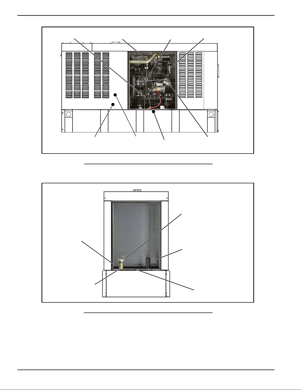
Fuel Return Hose
Coolant Overflow
Reservoir
Fuel Filter/Air Bleed
Coolant
Drain Hose
Fuel Supply Hose
Figure 5-3. Left Side View
Battery
Breather Canister
and Filter
Governor
Linkage
Fuel Tank
Primary Vent
Emergency Vent
Primary Tank
Fuel Filler Spout
Emergency Vent
Secondary Tank
Fuel Level Gauge
Figure 5-4. Front View
NOTE: The 3.4L engine is depicted in the artwork used in this manual. The location and appearance of some
components may vary between engine models.
28 Owner’s Manual for Stationary Diesel Generators
Page 35
5.2 — Access Panels
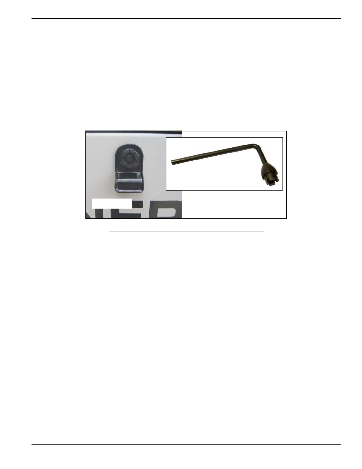
Access panels are located at both the front and sides of the enclosure.
5.2.1— Removal
1. Insert key into latch and rotate counterclockwise 1/2 turn. See Figure 5-5.
2. Raise panel using thumb latch.
5.2.2— Installation
1. Lower panel into position using thumb latch.
2. Insert key into latch and rotate clockwise 1/2 turn.
Maintenance
Key
Thumb Latch
Figure 5-5. Access Panel Key
Owner’s Manual for Stationary Diesel Generators 29
Page 36
Maintenance
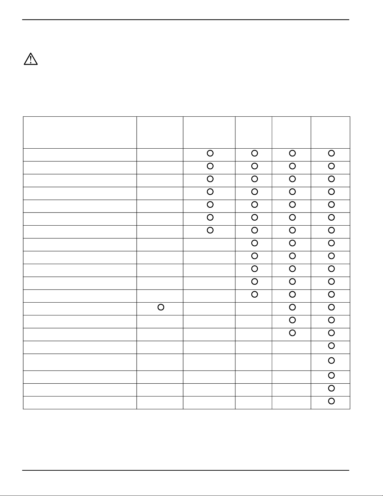
5.3 — Service Maintenance Intervals
NOTE: Use only Genuine Generac parts to ensure warranty coverage.
All generator service must be performed by a qualified service person only.
It is important to perform all maintenance at the interval specified in the Service Maintenance Schedule. This ensures
safe and proper operation, as well as compliance with applicable emissions standards. Critical emissions maintenance
must be performed for the Emissions Warranty to remain valid. Service and repairs may be performed by any qualified
service technician or repair shop.
Observe the maintenance tasks and intervals shown in the table below.
Service
Check Fuel Level and Fill
Drain Fuel Filter
Check Fuel Lines and Hoses
Check Coolant Level
Check Coolant Hoses
Check Radiator for Clogging
Check Lubricating Oil Level
Check Battery Condition/Fluid Level
Check/Adjust V-Belt Tension
Replace Air Filter Element
Drain Breather Canister and Replace Filter
Lubricate Governor Rod Linkage
30 Hours
Engine Break In
Daily If Running
Continuously
Schedule A
Every
Year or
125 Hours
Schedule B
Every
2 Years or
250 Hours
Schedule C
Every
1000 Hours
Replace Lubricating Oil and Oil Filter
Replace Fuel Filter Element
Drain/Flush Coolant System
Inspect Fuel Tank
Check/Adjust Fuel Injection Valve
Pressure
Adjust Intake/Exhaust Valve Clearance
Check/Adjust Fuel Injection Pump Timing
Tighten Critical Fasteners
NOTE: If the unit reaches a Schedule A or Schedule B maintenance interval with 900 to 999 total hours, have
an authorized service provider perform the Schedule C maintenance tasks as well (and reset the A-B-C/Year
maintenance schedule counter).
30 Owner’s Manual for Stationary Diesel Generators
Page 37
Maintenance
5.4 — Remove From Service
To ensure safety, follow the steps below prior to inspection, maintenance or service.
IMPORTANT NOTE: If currently experiencing a utility outage, see Subsection 6.3 —Removal From Service
During Utility Outages for special instructions.
1. Open the viewing window. See Subsection 3.5 —Open Viewing Window.
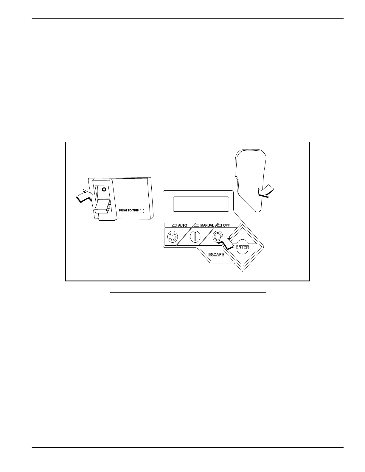
2. Move the Main Circuit Breaker switch down to the OFF (Open) position. See A of Figure 5-6.
3. Press the OFF key on the control panel keypad. The red LED above the key illuminates to confirm that the sys-
tem is in the OFF mode. See B of Figure 5-6.
4. Remove T1 fuse from transfer switch.
5. Pull up rubber flap covering fuse holder and remove 7.5 amp fuse. See C of Figure 5-6.
6. Place a DO NOT OPERATE tag or placard on both the control panel and transfer switch.
7. If the unit has been running, wait five minutes for the engine to cool.
A
OFF
Main Circuit Breaker
5.5 — 30 Hour Break-In
Perform the following task:
• Replace Lubricating Oil and Oil Filter
7.5 Amp Fuse
and USB Port
LCD and Keypad
Figure 5-6. Generator Control Panel
C
B
NOTE: See Subsection 5.8.1 under Schedule B Maintenance.
5.6 — Daily Maintenance (If Running Continuously)
Perform the following tasks:
• Check Fuel Level and Fill • Check Coolant Hoses
• Drain Fuel Filter • Check Radiator for Clogging
• Check Fuel Lines and Hoses • Check Lubricating Oil Level
• Check Coolant Level
NOTE: See Subsection 5.7.1 through Subsection 5.7.6 under Schedule A Maintenance.
Owner’s Manual for Stationary Diesel Generators 31
Page 38
Maintenance
5.7 — Schedule A Maintenance
NOTE: Perform Schedule A maintenance once each year or after 125 hours of service, whichever comes first.
5.7.1— Preliminary Instructions
1. See Subsection 5.4 —Remove From Service.
2. Remove access panels at the front and both sides of the enclosure. See Subsection 5.2 —Access Panels.
3. Remove battery negative cable (black) from battery negative (-) terminal.
NOTE: For general location of components, see Subsection 5.1 —Component Locations.
5.7.2— Check Fuel Level and Fill
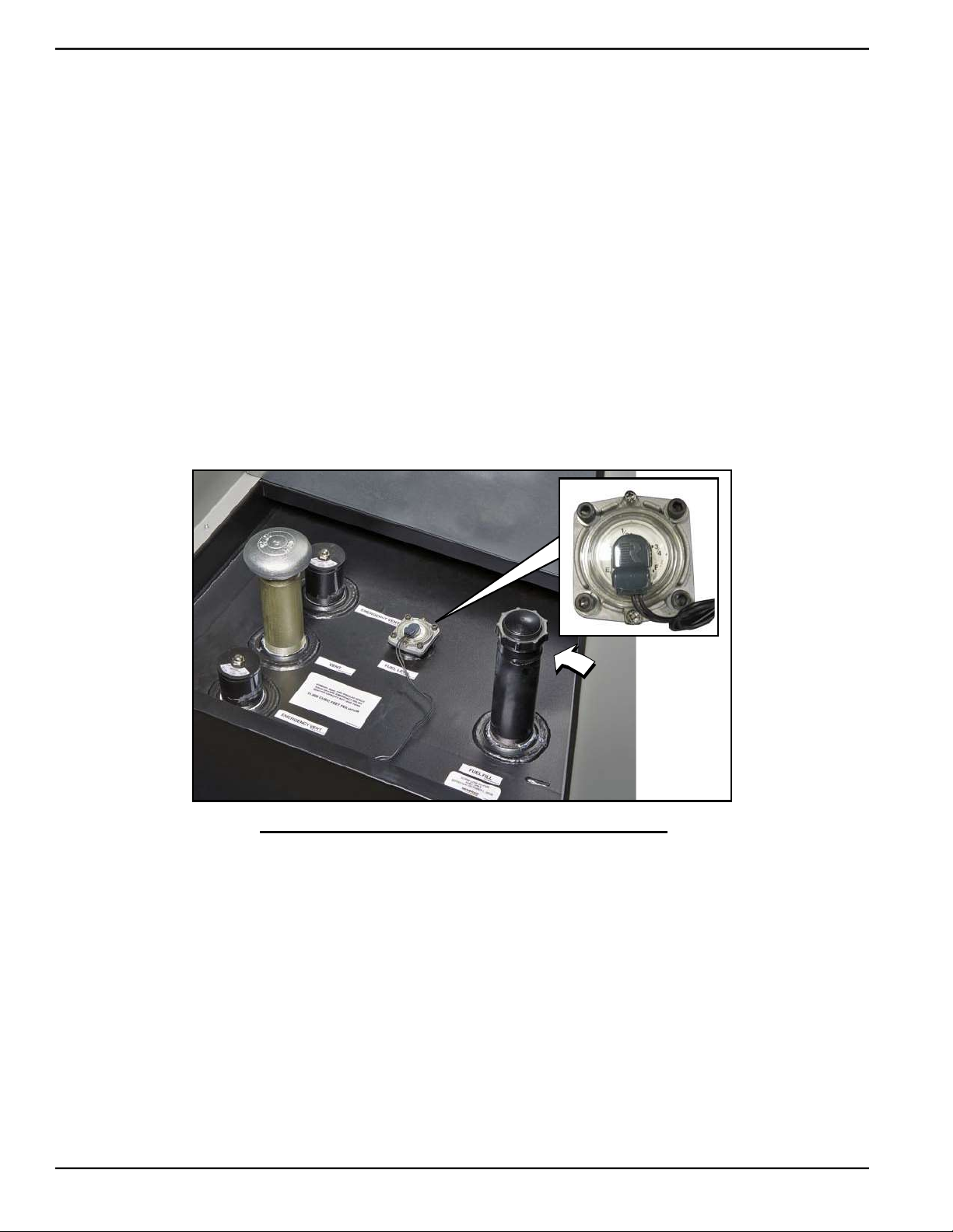
1. Observe fuel gauge to note level of fuel in tank. See Figure 5-7.
2. Remove fuel fill cap from filler pipe.
3. Add fuel until needle on fuel gauge approaches the F(ull) mark.
4. Install fuel fill cap onto filler pipe.
Figure 5-7. Check Fuel Level Gauge and Fill
5.7.3— Drain Fuel Filter and Check Fuel Lines/Hoses
1. Slowly loosen water drain plug. See Figure 5-8.
2. Place a shop rag under the drain to catch any loss of water/fuel.
3. Work priming pump until water is drained and replaced by solid fuel. Tighten the water drain plug.
4. Check fuel filter and fuel lines/hoses for leaks. Tighten filter, fittings and hose clamps, if necessary.
5. Check hoses for nicks, cuts, tears or general deterioration. Replace as necessary.
32 Owner’s Manual for Stationary Diesel Generators
Page 39
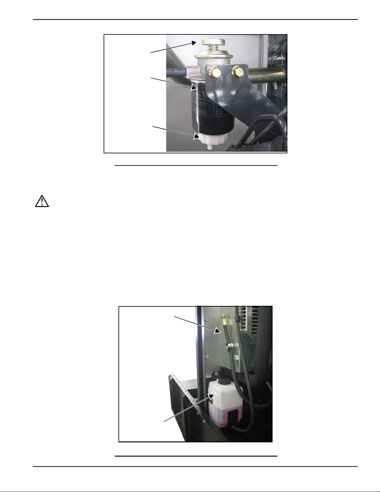
Priming
Pump
Fuel
Filter
Water
Drain Plug
Figure 5-8. Drain Water From Fuel Filter
5.7.4— Check Coolant Level and Hoses
Maintenance
CAUTION: Do not add coolant when the engine is hot. Steam and scalding fluids can cause severe
burns.
NOTE: On 2.3L models, remove ten screws to release louvered air discharge panel on left side of enclosure.
1. Verify that the coolant level is between the HOT and COLD marks on the overflow reservoir. See Figure 5-9.
NOTE: Coolant expands when hot, so the level may be higher than the HOT mark. Do not add coolant higher than the
HOT mark.
2. If the coolant level is below the COLD mark, remove fill cap from overflow reservoir and add coolant. See Sub-
section 2.4 —Coolant Water Treatment.
3. Check coolant hoses for leaks. Tighten hose clamps, if necessary.
4. Check hoses for nicks, cuts, tears or general deterioration. Replace as necessary.
NOTE: On 2.3L models, install louvered air discharge panel. Alternately tighten ten screws to 90 in-lbs using a cross-
wise pattern.
Drain Hose
Coolant
Reservoir
Figure 5-9. Coolant Overflow Reservoir and Drain Hose
Owner’s Manual for Stationary Diesel Generators 33
Page 40
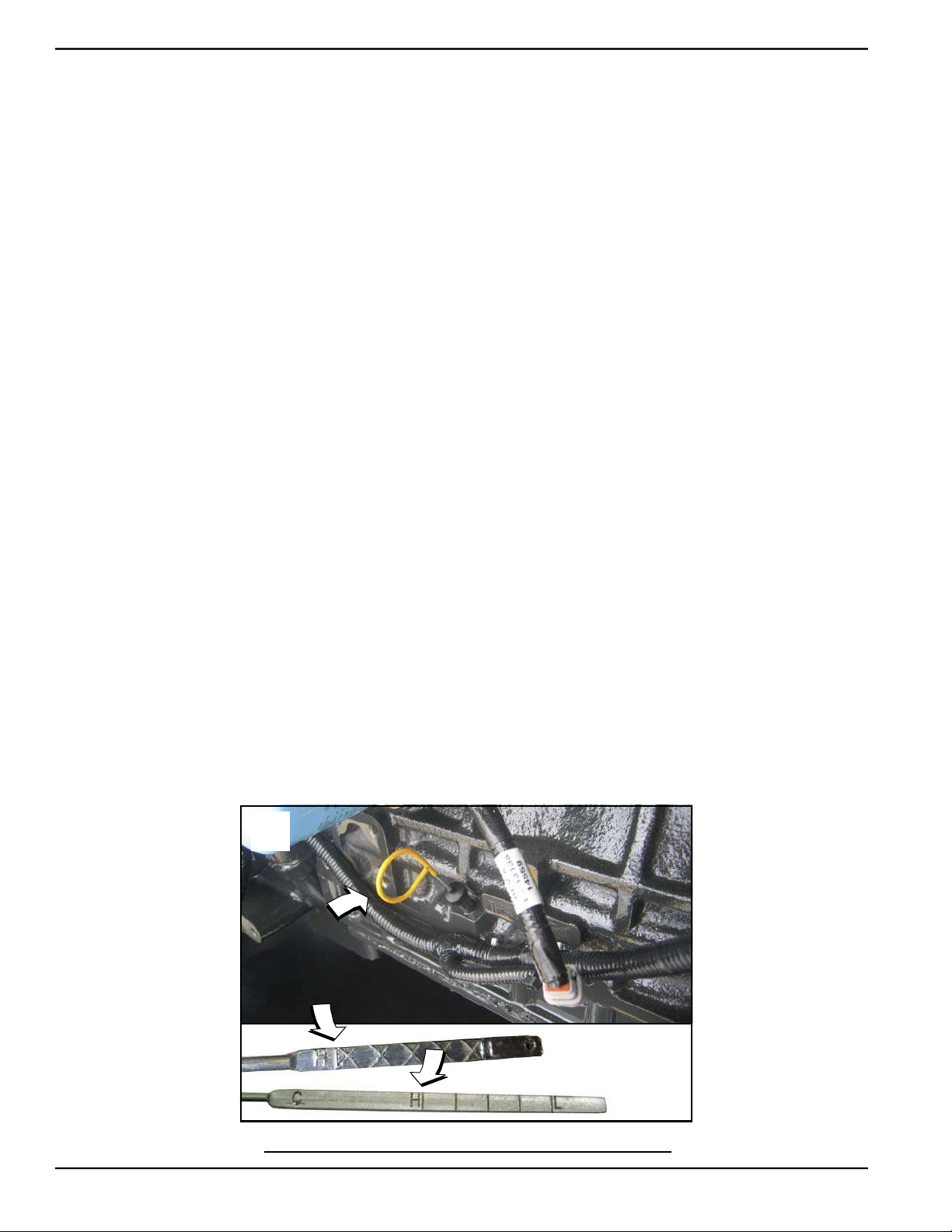
Maintenance
5.7.5— Check Radiator for Clogging
Direct beam of flashlight through openings in fan guard to inspect the radiator fins. Carefully look for debris, accumulations of dirt or other deposits. If necessary, clean as follows:
1. On right side of enclosure, loosen two clamps at each end of turbocharger exhaust outlet pipe. Remove pipe,
clamps and rubber couplings from engine.
2. Remove oil drain hose from holding clamp.
3. Remove four screws with nylon washers to release fan guard from radiator shroud.
4. On left side of enclosure, loosen two clamps at each end of air intake pipe. Remove pipe, clamps and rubber
couplings from engine.
5. Remove coolant hoses from holding clamps.
6. Remove four screws with nylon washers to release fan guard from radiator shroud.
7. Carefully remove any debris from radiator fins. Use warm soapy water and a soft bristled brush to remove dirt
and other deposits, if necessary.
8. On left side of enclosure, install four screws with nylon washers to fasten fan guard to radiator shroud.
9. Install coolant hoses into holding clamps.
10. Install clamps and rubber couplings onto each end of air intake pipe. Install pipe to air heater and radiator shroud.
Tighten clamps.
11. On right side of enclosure, install four screws with nylon washers to fasten fan guard to radiator shroud.
12. Install oil drain hose into holding clamp.
13. Install clamps and rubber couplings onto each end of turbocharger exhaust outlet pipe. Install pipe to turbo-
charger outlet and radiator shroud. Tighten clamps.
5.7.6— Check Lubricating Oil Level
1. Remove dipstick and wipe with a clean cloth. See A of Figure 5-10.
2. Completely insert the dipstick and then remove it.
3. Verify that the oil level is at or near the H(igh) mark.
NOTE: Each hash mark or line below the H(igh) mark represents one liter. Add oil whenever the level is one liter or
more below the H(igh) mark.
4. If necessary, remove the oil fill cap and slowly add oil until the level is at the H(igh) mark. See B of Figure 5-10.
DO NOT OVERFILL.
5. Install dipstick and oil fill cap.
6. Check oil drain hose for leaks. Check hose for nicks, cuts, tears or general deterioration. Replace as necessary.
A
2.3 Liter
2.4 Liter
B
3.4 Liter
Figure 5-10. Oil Level Dipstick
34 Owner’s Manual for Stationary Diesel Generators
Page 41
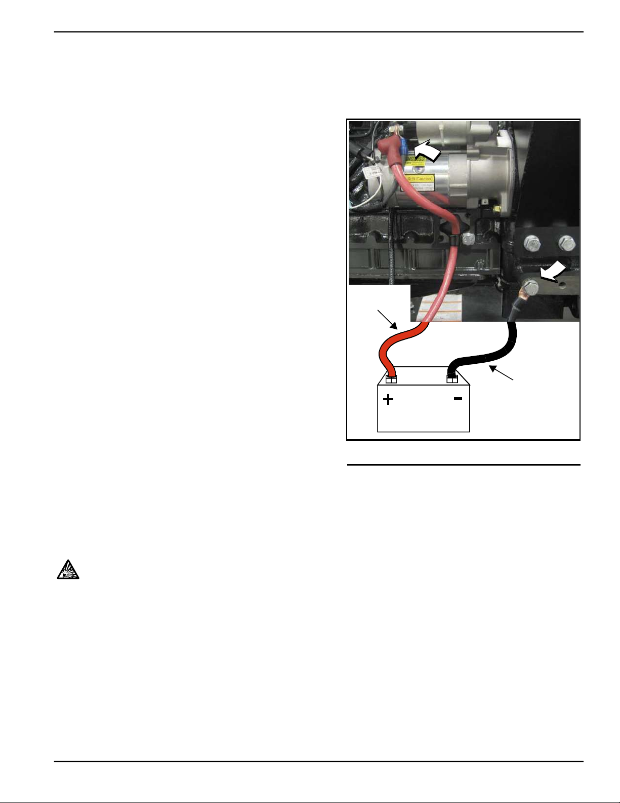
Maintenance
5.7.7— Check Battery Condition/Fluid Level
5.7.7.1— Check Condition and Clean
NOTE: To access battery on 2.3L models, remove ten screws to release louvered air intake panel on left side of enclo-
sure.
1. Verify that top of battery is clean and dry. Dirt and electro-
lyte on top of the battery can cause battery to self-discharge. Clean battery top with a solution of baking soda
(sodium bicarbonate) and water (5 teaspoons baking
soda per quart or liter of water). When solution stops bubbling, rinse off the battery with clean water.
2. Clean cable clamps and battery terminals using a wire
brush or sandpaper to remove any oxidation.
3. Inspect battery screws, clamps and cables for breakage,
loose connections and corrosion. Tighten and clean as
necessary.
4. Check the battery posts for melting or damage caused by
over tightening.
5. Inspect battery for discoloration, raised top or a warped
or distorted case, which might indicate that the battery
has been frozen, overheated or overcharged.
6. Inspect the battery case for cracks or leaks.
7. Check the battery fluid level of unsealed batteries. See
Subsection 5.7.7.2—Check Fluid Level.
8. Check the battery state of charge. See Subsection
5.7.7.3—Check State of Charge.
NOTE: On 2.3L models, install louvered air intake panel. Alternately tighten ten screws to 90 in-lbs using a crosswise pattern.
Red Lead
From Starter
Black Lead
To Fra m e
Battery
5.7.7.2— Check Fluid Level
Check the fluid level of unsealed batteries. If necessary, fill with
Figure 5-11. Battery Cable Connections
distilled water only. DO NOT use tap water.
5.7.7.3— Check State of Charge
Check the state of charge using a Digital Multimeter. Recharge and retest if state of charge is below manufacturer's
recommendations. Replace battery if necessary.
5.7.7.4— Battery Replacement
Removal
CAUTION: Always disconnect the negative battery cable first. If the positive cable should contact
ground with the negative cable installed, the resulting sparks may cause a battery explosion which
could result in serious injury.
2.3L Models
1. Remove battery negative cable (black) from battery negative (-) terminal.
2. Remove battery positive cable (red) from battery positive (+) terminal.
3. Install rubber protective cover over battery positive (+) terminal.
4. Loosen two screws with nylon washers to release battery hold-down clamp from battery tray.
5. Grasp battery strap next to battery positive (+) terminal, and lift battery.
6. When battery tilts sideways, remove from opening.
7. Remove rubber protective cover from battery positive (+) terminal.
Owner’s Manual for Stationary Diesel Generators 35
Page 42
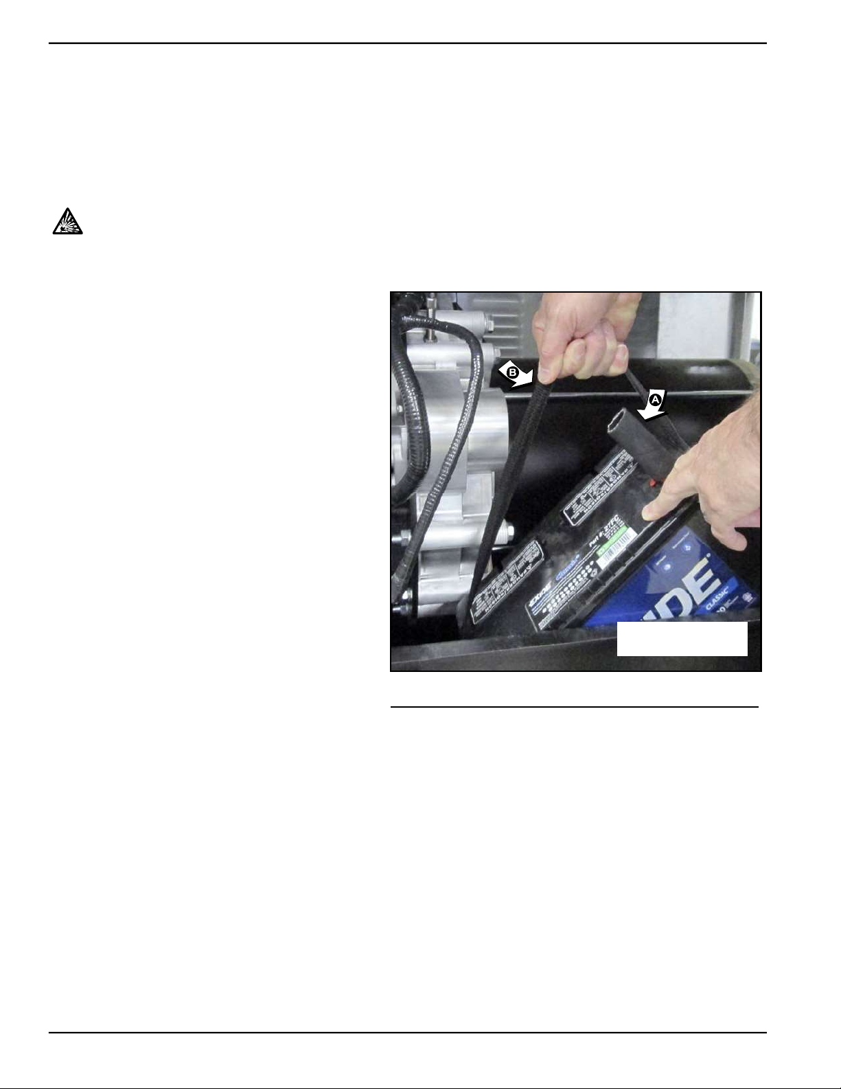
Maintenance
2.4L/3.4L Models
1. Remove battery negative cable (black) from battery negative (-) terminal.
2. Remove battery positive cable (red) from battery positive (+) terminal.
3. Loosen two screws with nylon washers to release battery hold-down clamp.
4. Remove battery from tray.
Installation
CAUTION: Always connect the positive battery cable first. If the positive cable should contact ground
with the negative cable installed, the resulting sparks may cause a battery explosion which could
result in serious injury.
2.3L Models
1. Install rubber protective cover over battery posi-
tive (+) terminal. See A of Figure 5-12.
2. Grasp battery strap next to battery positive (+)
terminal, and lift battery. See B of Figure 5-12.
3. When battery tilts sideways, insert into opening.
4. Return battery to the horizontal position while
sliding it onto battery tray.
5. Tighten two screws with nylon washers to
secure hold-down clamp to battery tray.
6. Remove rubber protective cover from battery
positive (+) terminal.
7. Install battery positive cable (red) to battery
positive (+) terminal.
8. Install battery negative cable (black) to battery
negative (-) terminal.
2.4L/3.4L Models
Installation
1. Install battery onto tray.
2. Tighten two screws with nylon washers to
secure hold-down clamp to battery tray.
3. Install battery positive cable (red) to battery
positive (+) terminal.
4. Install battery negative cable (black) to battery
negative (-) terminal.
A = Protective Cover
B = Battery Strap
Figure 5-12. Install Battery (2.3L Models)
36 Owner’s Manual for Stationary Diesel Generators
Page 43
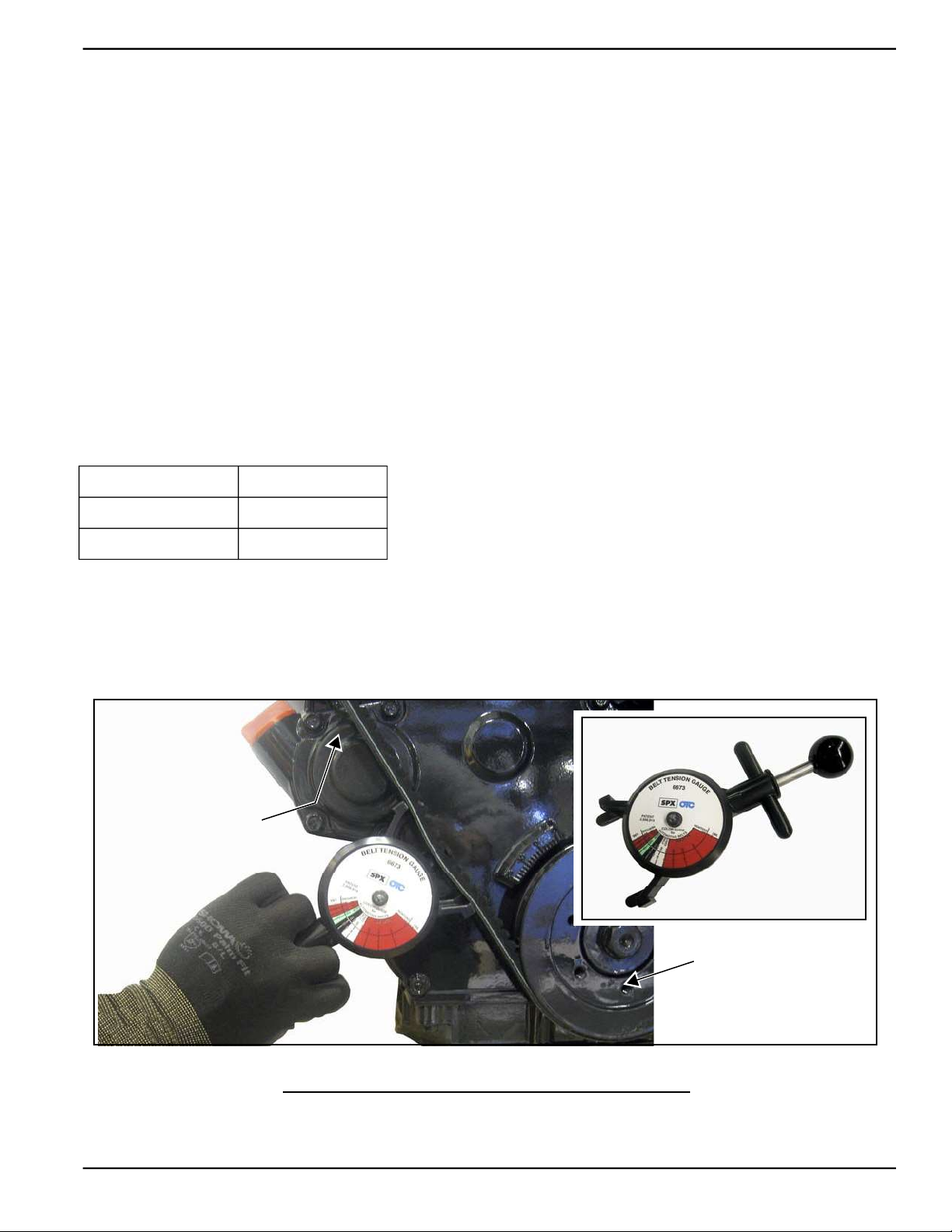
Maintenance
5.7.8— Check and Adjust V-Belt
5.7.8.1— Check
Check the V-belt deflection. Too little belt deflection accelerates belt wear, while too much deflection leaves the pulley
idle, overheats the engine, and no-load is generated. Adjust the belt deflection as follows:
1. On right side of enclosure, loosen two clamps at each end of turbocharger exhaust outlet pipe. Remove pipe,
clamps and rubber couplings from engine.
2. Remove oil drain hose from holding clamp.
3. Remove four screws with nylon washers to release fan guard from radiator shroud.
4. Perform visual inspection as follows:
• Inspect belt for cracks, fraying, excessive wear or other damage.
• Verify that belt is free of grease and oil. Replace belt if contaminated.
NOTE: Use a solution of soap and warm water to clean pulleys, if necessary. Avoid use of solvents, but if used, always
follow by a soap and water wash.
5. Using a suitable gauge, apply 22 Ibs (10 kgf) force midway between the crankshaft and alternator pulleys. See
Figure 5-13.
6. Take note of gauge reading. If belt deflection is not within specification, see Subsection 5.7.8.2—Adjust.
Belt Condition Deflection
New 8-12 mm
Used 10-15 mm
7. Install four screws with nylon washers to fasten fan guard to radiator shroud.
8. Install oil drain hose into holding clamp.
9. Install clamps and rubber couplings onto each end of turbocharger exhaust outlet pipe. Install pipe to turbo-
charger outlet and radiator shroud. Tighten clamps.
Belt Deflection Gauge
Alternator Pulley
Crankshaft Pulley
Figure 5-13. Check V-Belt Deflection
Owner’s Manual for Stationary Diesel Generators 37
Page 44
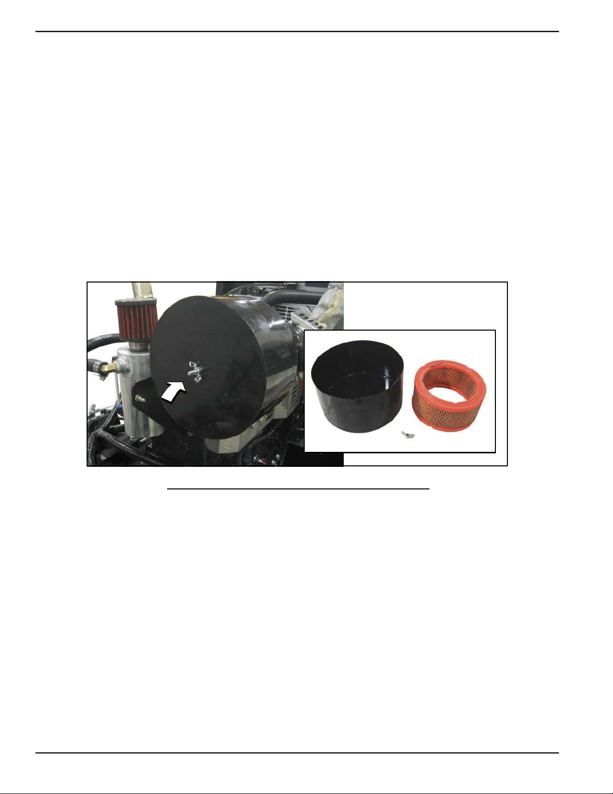
Maintenance
5.7.8.2— Adjust
1. Loosen tension adjuster screw (top). Loosen hex nut on pivot screw (bottom). Rotate alternator outward to
reduce belt deflection, rotate inward to increase belt deflection.
2. Tighten tension adjuster screw (top). Tighten hex nut on pivot screw (bottom).
3. Recheck belt deflection and repeat steps as necessary.
5.7.9— Replace Air Filter Element
1. Remove wing nut from threaded rod to release air cleaner cover. See Figure 5-14.
2. Remove the air filter element and discard.
3. Thoroughly clean air cleaner cover of any dust, dirt, or debris.
4. Place new air filter element against adapter flange.
NOTE: The air filter element is not directional.
5. Install air cleaner cover over threaded rod. Install wing nut and tighten until snug.
Element
Cover
Wing Nut
Figure 5-14. Air Cleaner Cover and Filter Element
5.7.10— Drain Breather Canister and Replace Filter
NOTE: This procedure only applies to turbocharged engines (2.4L/3.4L models).
1. Observe sight glass for level of oil in canister. See Figure 5-15.
2. When oil level approaches top of sight glass, remove plug at bottom of canister to drain oil.
3. Install drain plug at bottom of canister and tighten until snug.
4. Loosen clamp and remove filter element.
5. Install new filter element onto canister and tighten clamp.
6. Inspect hoses for nicks, cuts, tears or signs of deterioration. Replace as necessary.
7. Check for leakage. Tighten clamps if leaks are found.
NOTE: Dispose of used fuel filter at a proper collection center.
38 Owner’s Manual for Stationary Diesel Generators
Page 45
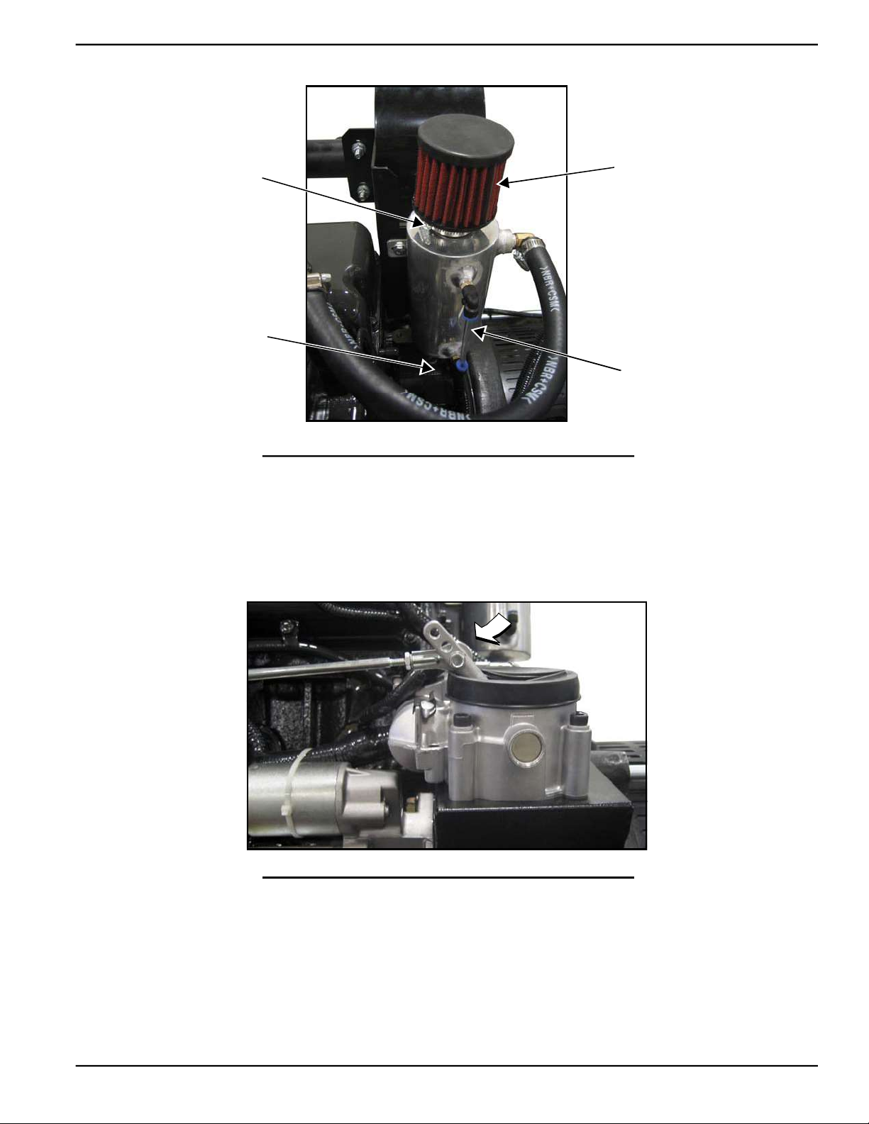
Clamp
Drain Plug
Maintenance
Filter
Element
Sight
Glass
Figure 5-15. Drain Breather Canister and Replace Filter
5.7.11— Lubricate Governor Rod Linkage
1. Lubricate both ends of rod with a silicone spray. See Figure 5-16.
2. Verify that rod moves freely without binding.
Figure 5-16. Lubricate Governor Rod Ends
5.7.12— Final Instructions
1. Install battery negative cable (black) onto battery negative (-) terminal.
2. Install access panels at the front and both sides of the enclosure. See Subsection 5.2 —Access Panels.
3. See Subsection 5.10 —Return To Service.
Owner’s Manual for Stationary Diesel Generators 39
Page 46
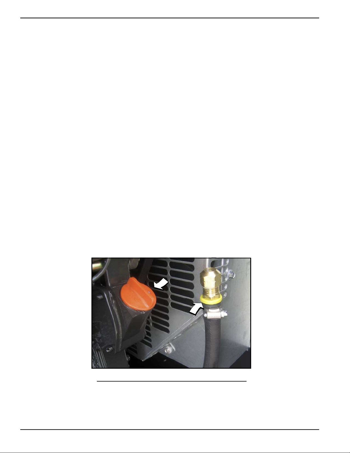
Maintenance
5.8 — Schedule B Maintenance
NOTE: Perform Schedule B maintenance every two years or after 250 hours of service, whichever comes first.
Before proceeding below, first perform all tasks listed under Schedule A Maintenance.
NOTE: For general location of components, see Subsection 5.1 —Component Locations.
5.8.1— Replace Lubricating Oil and Oil Filter
1. Remove oil drain hose from holding clamp. See Figure 5-17.
2. Use one wrench to hold hex on hose fitting (to prevent rotation), and use second wrench to remove drain plug.
3. Drain oil into a suitable container.
4. Install drain plug onto end of oil drain hose.
5. Install oil drain hose into holding clamp.
6. Rotate oil filter counterclockwise to remove from oil filter adapter.
7. Apply a light coat of clean engine oil to gasket of new oil filter.
8. Install oil filter by hand until gasket just contacts oil filter adapter. Tighten oil filter an additional 3/4 to one full turn.
9. Remove fill cap and fill engine with the recommended oil. See Subsection 2.3 —Engine Oil Recommendations.
10. Install fill cap.
11. Install battery negative cable (black) onto battery negative (-) terminal.
12. Pull up rubber flap covering fuse holder and install 7.5 amp fuse.
13. Press the MANUAL key on the control panel keypad to start the engine.
14. Allow the engine to run for one minute. Check for leaks while the engine is running.
15. Press the OFF key on the control panel keypad.
16. Wait a few minutes for the engine to cool and to allow oil to drain back to the oil pan.
17. Check oil level and add oil as necessary. DO NOT OVERFILL.
18. Install fill cap.
NOTE: Dispose of used oil and oil filter at a proper collection center.
Figure 5-17. Oil Fill Cap and Drain Hose
40 Owner’s Manual for Stationary Diesel Generators
Page 47
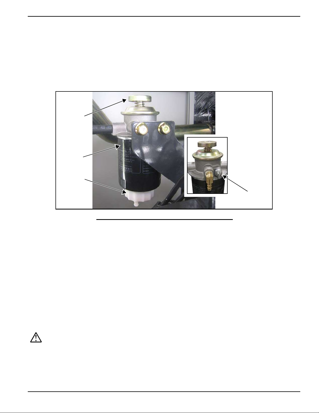
Maintenance
5.8.2— Replace Fuel Filter
1. Slowly loosen water drain plug. See Figure 5-18.
2. Rotate filter counterclockwise to remove from filter adapter.
3. Install new filter by hand until gasket just contacts filter adapter. Tighten filter an additional 3/4 to one full turn.
4. Install water drain plug.
NOTE: Dispose of used fuel filter at a proper collection center.
5. See Subsection 5.8.2.1—Prime Fuel System.
Priming
Pump
Fuel
Filter
Water
Drain Plug
Air Bleed
Screw
Figure 5-18. Prime Fuel System
5.8.2.1— Prime Fuel System
1. Loosen the air bleed screw and work priming pump until bubbles are observed. Place a shop rag near the air
bleed screw to catch any loss of fuel.
2. When all bubbles are purged and replaced by a solid stream of fuel, depress pump handle and tighten the air
bleed screw.
3. Check for leaks.
5.8.3— Drain/Flush Coolant System
NOTE: On 2.3L models, remove ten screws to release louvered air discharge panel on left side of enclosure.
1. Disconnect and empty coolant overflow reservoir.
2. Install and connect coolant overflow reservoir.
CAUTION: Verify that the engine is cool before removing the radiator cap. The cooling system is under
pressure, so steam and hot liquid can come out forcefully when the cap is loosened.
3. Slowly unscrew radiator cap.
4. Locate drain cock at bottom left side of radiator. Rotate hex fitting to open drain cock. See A of Figure 5-19.
5. Remove coolant drain hose from holding clamp.
6. Use wrench to hold hex on hose fitting (to prevent rotation), and use second wrench to remove drain plug.
Owner’s Manual for Stationary Diesel Generators 41
Page 48
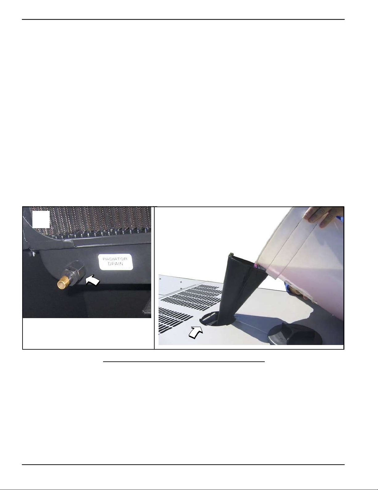
Maintenance
7. Drain coolant into a suitable container.
8. Install plug at end of drain hose.
9. Install drain hose in holding clamp.
10. Rotate hex fitting to close radiator drain cock.
11. Obtain at least 2.8 gallons (10.6 liters) of coolant. See Subsection 2.4 —Coolant Water Treatment.
12. Rotate and remove plastic cover at top of enclosure and insert funnel into filler neck. See B of Figure 5-19.
13. Slowly pour coolant into filler neck until radiator is full.
14. Install radiator cap.
15. Press the MANUAL key on the control panel keypad to start the engine. The blue LED above the key illuminates
to confirm that the system is in the MANUAL mode.
16. Allow engine to run until the thermostat opens, as indicated by heating of the top radiator hose.
17. Check coolant hoses for leaks. Tighten clamps, if necessary.
18. Press the OFF key on the control panel keypad to shut the engine down.
19. Wait five minutes for the engine to cool.
20. Repeat steps 4-20 to drain and refill cooling system.
21. Install plastic cover at top of enclosure and rotate until tight.
22. Check hoses for nicks, cuts, tears or general deterioration. Replace as necessary.
NOTE: On 2.3L models, start ten screws to install louvered air discharge panel. Alternately tighten screws to 90 in-lbs
using a crosswise pattern.
A
NOTE: Drain hose removed for
illustration purposes.
5.8.4— Final Instructions
B
Figure 5-19. Drain/Fill Coolant System
1. Install left and right side access panels. See Subsection 5.2 —Access Panels.
2. See Subsection 5.10 —Return To Service.
42 Owner’s Manual for Stationary Diesel Generators
Page 49
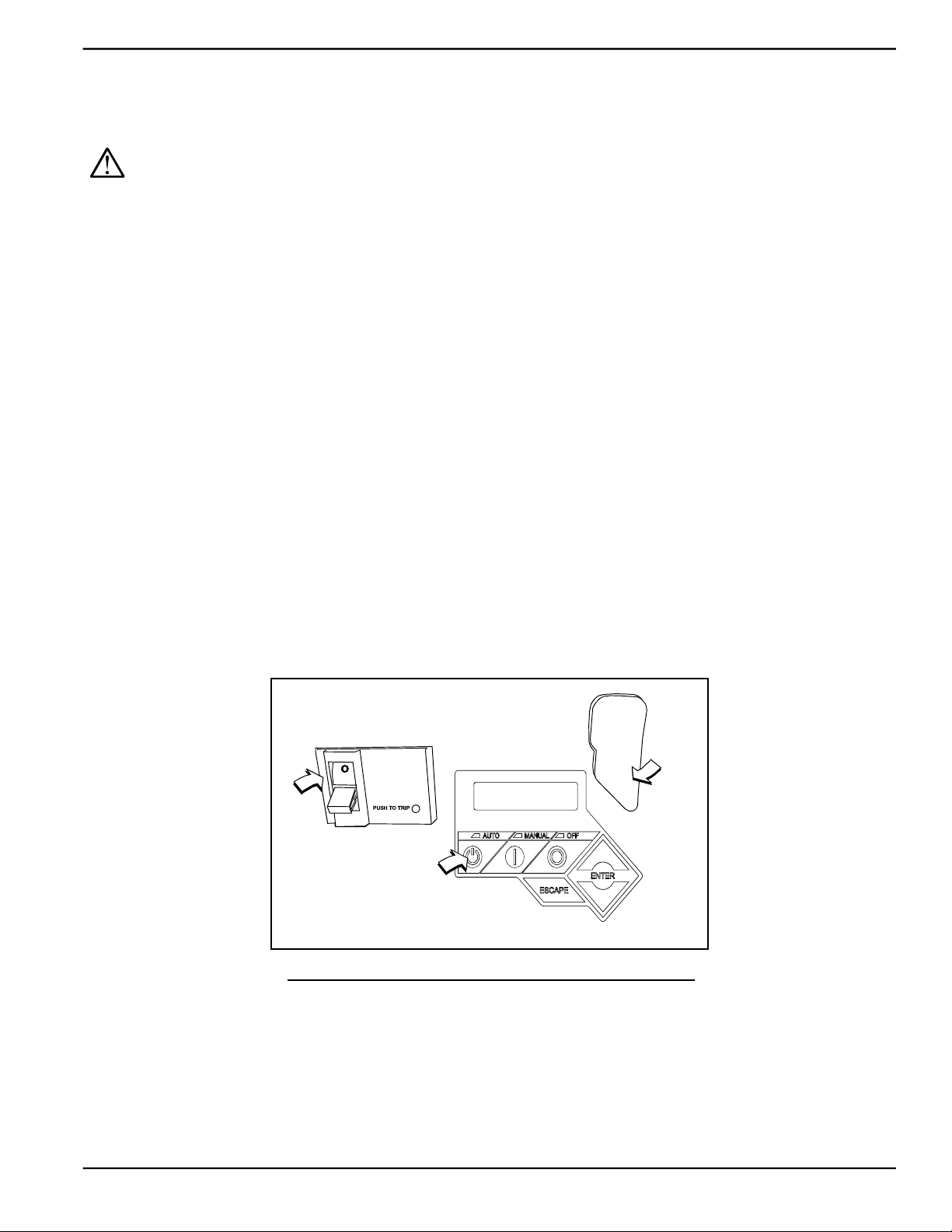
Maintenance
5.9 — Schedule C Maintenance
NOTE: Perform Schedule C maintenance after 1000 hours of service. Before proceeding below, first perform all
tasks listed under Schedule A Maintenance and Schedule B Maintenance.
CAUTION: The following procedures require special tools and skills. Contact a Generac Dealer or an
authorized service provider to perform these tasks.
• Inspect Fuel Tank
• Check/Adjust Fuel Injection Valve Pressure
• Check/Adjust Fuel Injection Pump Timing
• Adjust Intake/Exhaust Valve Clearance
• Tighten Critical Fasteners
NOTE: Reset the A-B-C/Year time maintenance schedule counter using the Dealer Sub Menu (password required).
5.10 — Return To Service
After inspection, maintenance or service of the generator, return the unit to service following the steps below.
1. Pull up rubber flap covering fuse holder and install 7.5 amp fuse. See A of Figure 5-20.
2. Install T1 fuse in transfer switch.
3. Press the AUTO key on the control panel keypad. The green LED above the key illuminates to confirm that the
system is in the AUTO mode. See B of Figure 5-20.
4. Move the Main Circuit Breaker switch up to the ON (Closed) position. See C of Figure 5-20.
5. Close the viewing window.
6. Remove the DO NOT OPERATE tag or placard from both the control panel and transfer switch.
7. Reset the time and date.
7.5 Amp Fuse Holder
C
OFF
Main Circuit Breaker
LCD and Keypad
Figure 5-20. Generator Control Panel
A
B
Owner’s Manual for Stationary Diesel Generators 43
Page 50

Maintenance
This page intentionally left blank.
44 Owner’s Manual for Stationary Diesel Generators
Page 51
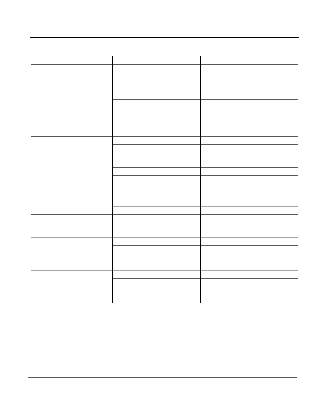
Section 6 Troubleshooting
6.1 — Engine Troubleshooting
Problem Cause Correction
Fuse blown.
Loose, corroded or defective bat-
The engine will not crank.
The engine cranks but will not
start.
The engine starts hard and runs
rough.
The generator is set to OFF, but
the engine continues to run.
There is no AC output from the
generator.
There is no transfer to standby
after utility source failure.
Unit consumes large amounts of
oil.
* Contact an Authorized Service Dealer for assistance.
tery cables.
Defective starter contact.
Defective starter motor.
Dead Battery. Charge or replace battery.
Out of fuel. Replenish fuel. Turn on fuel valve.
Defective fuel solenoid. *
Open F1 5 amp fuse.
Defective fuel system. *
No fuel to pump. Prime fuel system.*
Air cleaner plugged or damaged. Check/replace air cleaner.
Defective keypad. *
Defective control board. *
Main line circuit breaker is in the
OFF (OPEN) position.
Generator internal failure. *
Defective transfer switch coil. *
Defective transfer relay. *
Transfer relay circuit open. *
Defective control logic board. *
Engine over filled with oil. Adjust oil to correct level.
Engine breather defective. *
Incorrect oil type or viscosity. See Engine Oil Recommendations.
Damaged gasket, seal or hose. Check for oil leaks.
Replace 7.5 amp fuse in generator control panel. Correct short circuit condition if fuse blows again.
Tighten, clean or replace as necessary.*
Tighten, clean or replace as necessary.*
Tighten, clean or replace as necessary.*
Replace F1 5 amp fuse if fuse blows
again.*
Reset circuit breaker to ON (CLOSED)
position.
Owner’s Manual for Stationary Diesel Generators 45
Page 52
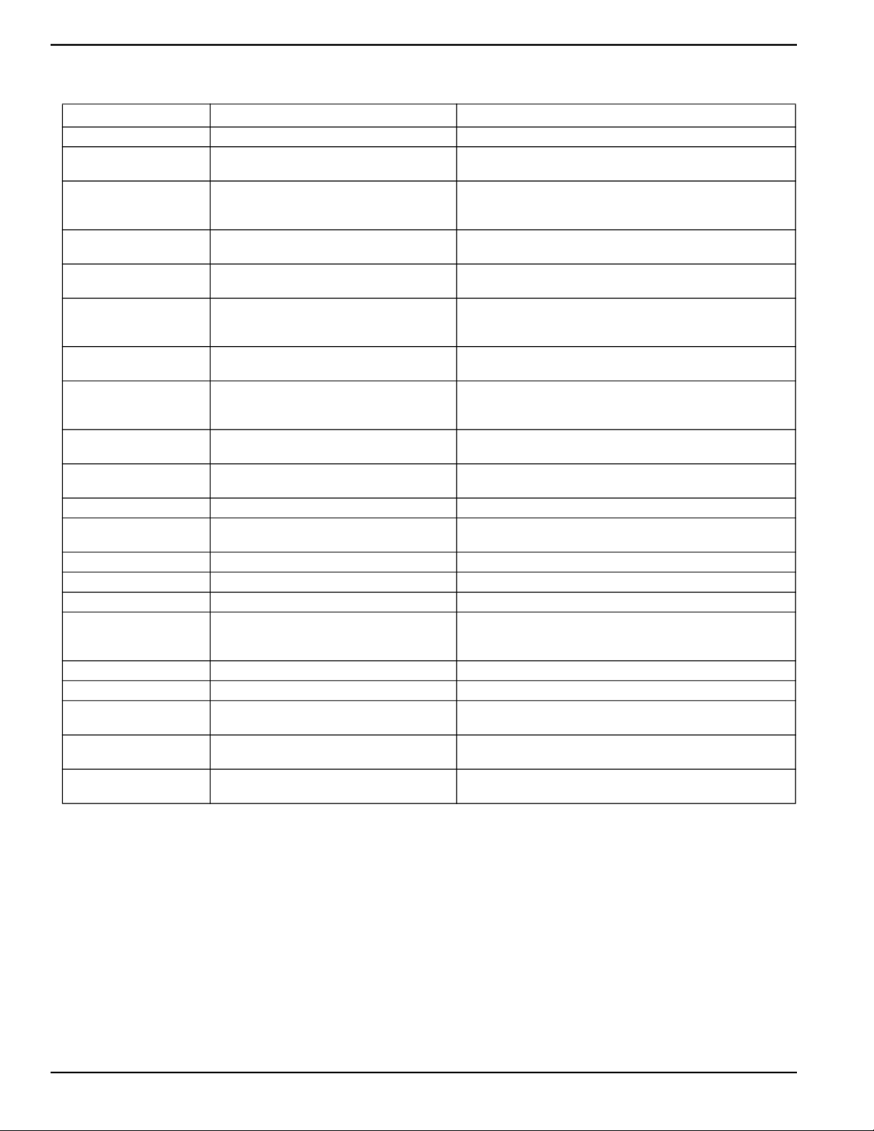
Troubleshooting
6.2 — Controller Troubleshooting
Active Alarm Problem Solution
NOT ACTIVATED Unit will not start in AUTO with utility loss. Refer to activation section in Owner’s Manual.
NONE Unit running in AUTO but no power in house.
NONE Unit will not start in AUTO with utility loss.
HIGH
TEMPERATURE
OVERLOAD Unit shuts down during operation.
RPM SENSE LOSS
LOW OIL
PRESSURE
RPM SENSE LOSS Unit will not start in AUTO with utility loss.
OVERCRANK Unit will not start in AUTO with utility loss.
FUSE PROBLEM Unit will not start in AUTO with utility loss.
OVERSPEED Unit will not start in AUTO with utility loss. Contact servicing dealer.
UNDER
VOLTAGE
UNDERSPEED Unit will not start in AUTO with utility loss. Contact servicing dealer.
MISWIRE Unit will not start in AUTO with utility loss. Contact servicing dealer.
OVERVOLTAGE Unit will not start in AUTO with utility loss. Contact servicing dealer.
LOW BATTERY Warning active.
BATTERY PROBLEM Warning active. Contact servicing dealer.
CHARGER WARNING Warning active. Contact servicing dealer
SERVICE SCHEDULE A Warning active.
SERVICE SCHEDULE B Warning active.
SERVICE SCHEDULE C Warning active.
Unit shuts down during operation.
Unit was running and shuts down, attempts to
restart.
Unit will not start in AUTO with utility loss.
Unit will not start in AUTO with utility loss. Contact servicing dealer.
Check MLCB. Contact servicing dealer if MLCB is in the ON
position.
Check screen for start delay countdown. If the start up delay is
greater than expected, contact servicing dealer to adjust from 2
to 1500 seconds.
Check ventilation around the intake, exhaust and rear of generator. Contact serving dealer if no obstruction is found.
Clear alarm and remove household loads from the generator.
Put back in AUTO and restart.
Clear alarm and remove household loads from the generator.
Put back in AUTO and restart. If problem returns, contact servicing dealer to investigate possible fuel issue.
Check oil level. Add oil per Owner’s Manual. Contact servicing
dealer if oil level is correct.
Clear alarm. From the MAIN menu on the control panel, navigate to the BATTERY MENU. Contact servicing dealer if battery
is GOOD. Replace battery If CHECK BATTERY is displayed.
Clear alarm. Attempt to start the unit in MANUAL. If it does not
start or starts and runs rough, contact servicing dealer.
Check ATO 7.5 amp fuse. Replace with same type fuse if bad.
Contact servicing dealer if fuse is good.
Clear alarm. From the MAIN menu on the control panel, navigate to the BATTERY MENU. Contact servicing dealer if battery
is GOOD. Replace battery If CHECK BATTERY is displayed.
Perform SERVICE SCHEDULE A maintenance; press ENTER
to clear.
Perform SERVICE SCHEDULE B maintenance; press ENTER
to clear.
Perform SERVICE SCHEDULE C maintenance; press ENTER
to clear.
46 Owner’s Manual for Stationary Diesel Generators
Page 53

Troubleshooting
6.3 — Removal From Service During Utility Outages
If, during prolonged utility outages, the user wishes to remove the unit from service to conserve fuel, reduce run hours,
or to perform maintenance tasks, then complete the steps listed below.
IMPORTANT NOTE: Failure to abide by this procedure can result in equipment damage.
To remove the generator from service while running in AUTO and online, proceed as follows:
1. Turn the main utility disconnect to OFF (Open).
2. Open the viewing window. See Subsection 3.5 —Open Viewing Window.
3. Move the Main Circuit Breaker switch down to the OFF (Open) position.
4. Press the OFF key on the control panel keypad. The red LED above the key illuminates to confirm that the sys-
tem is in the OFF mode.
NOTE: If inspection and/or maintenance tasks are to be performed, complete the additional steps listed below.
5. Remove T1 fuse from transfer switch.
6. Pull up rubber flap covering fuse holder and remove 7.5 amp fuse.
7. Remove battery negative cable (black) from battery negative (-) terminal.
8. Place a DO NOT OPERATE tag or placard on both the control panel and transfer switch.
To return the generator to service, proceed as follows:
NOTE: If inspection and/or maintenance tasks were performed, start with step 1. If the unit was just shut down to conserve fuel or to reduce run hours, start at step 5.
1. Install battery negative cable (black) onto battery negative (-) terminal.
2. Pull up rubber flap covering fuse holder and install 7.5 amp fuse.
3. Install T1 fuse in transfer switch.
4. Remove the DO NOT OPERATE tag or placard from both the control panel and transfer switch.
5. Press the AUTO key on the control panel keypad. The green LED above the key illuminates to confirm that the
system is in the AUTO mode. Allow the generator to start and run for a few minutes.
6. Move the Main Circuit Breaker switch up to the ON (Closed) position.
7. Turn the main utility disconnect to ON (Closed).
8. Close the viewing window.
6.4 — Storage
6.4.1— Prepare For Storage
If the generator cannot be exercised every seven days and will be out of service longer than 90 days, prepare for storage as follows:
1. Open the viewing window. See Subsection 3.5 —Open Viewing Window.
2. Press the MANUAL key on the control panel keypad to start the engine. The blue LED above the key illuminates
to confirm that the system is in the MANUAL mode.
3. Allow the engine to run until it reaches normal operating temperature.
4. Press the OFF key on the control panel keypad. The red LED above the key illuminates to confirm that the sys-
tem is in the OFF mode.
5. Move the Main Circuit Breaker switch on the control panel down to the OFF (Open) position.
6. Pull up rubber flap covering fuse holder and remove 7.5 amp fuse.
7. Turn off utility power to the transfer switch.
8. Place a DO NOT OPERATE tag or placard on both the control panel and transfer switch.
Owner’s Manual for Stationary Diesel Generators 47
Page 54
Troubleshooting
9. Wait five minutes for the engine to cool.
10. Remove right side access panel. See Subsection 5.2 —Access Panels.
11. Remove oil drain hose from holding clamp.
12. Use one wrench to hold hex on hose fitting (to prevent rotation), and use second wrench to remove drain plug.
13. Drain oil into a suitable container.
14. Install drain plug onto end of oil drain hose.
15. Install oil drain hose into holding clamp.
16. Rotate oil filter counterclockwise to remove from oil filter adapter.
17. Apply a light coat of clean engine oil to gasket of new oil filter.
18. Install oil filter by hand until gasket just contacts oil filter adapter. Tighten oil filter an additional 3/4 to one full turn.
19. Remove oil fill cap and fill engine with the recommended oil. See Subsection 2.3 —Engine Oil Recommenda-
tions.
20. Install oil fill cap.
21. Install right side access panel. See Subsection 5.2 —Access Panels.
NOTE: Dispose of used oil and oil filter at a proper collection center.
22. Remove left side access panel. See Subsection 5.2 —Access Panels.
NOTE: On 2.3L models, remove ten screws to release louvered air intake panel.
CAUTION: Always disconnect the negative battery cable first. If the positive cable should contact
ground with the negative cable installed, the resulting sparks may cause a battery explosion which
could result in serious injury.
23. Remove battery negative cable (black) from battery negative (-) terminal.
24. Remove battery positive cable (red) from battery positive (+) terminal.
25. Remove two screws to release battery hold-down clamp from platform.
26. Remove battery and store on a wooden board in a cool, dry room. Do not store the battery on a concrete or
earthen floor.
27. Install left side access panel. See Subsection 5.2 —Access Panels.
NOTE: On 2.3L models, start ten screws to install louvered air intake panel. Alternately tighten screws to 90 in-lbs.
28. Thoroughly clean and wipe down the generator. See Subsection 2.7 —Corrosion Protection.
6.4.2— Return From Storage
To return the unit to service after storage, proceed as follows:
1. Thoroughly clean and wipe down the generator. See Subsection 2.7 —Corrosion Protection.
2. Remove left side access panel. See Subsection 5.2 —Access Panels.
NOTE: On 2.3L models, remove ten screws to release louvered air intake panel.
3. Install battery onto tray oriented with the negative (-) post toward the front of the enclosure.
4. Install two screws with nylon washers to secure battery hold-down clamp to tray.
5. Check battery. See Subsection 5.7.7—Check Battery Condition/Fluid Level..
CAUTION: Always connect the positive battery cable first. If the positive cable should contact ground
with the negative cable installed, the resulting sparks may cause a battery explosion which could
result in serious injury.
6. Install battery positive cable (red) onto battery positive (+) terminal.
7. Install battery negative cable (black) onto battery negative (-) terminal.
8. Install left side access panel. See Subsection 5.2 —Access Panels.
NOTE: On 2.3L models, start ten screws to install louvered air intake panel. Alternately tighten screws to 90 in-lbs.
9. Remove right side access panel. See Subsection 5.2 —Access Panels.
48 Owner’s Manual for Stationary Diesel Generators
Page 55

Troubleshooting
10. Check oil level and add oil as necessary. DO NOT OVERFILL.
11. Open the viewing window. See Subsection 3.5 —Open Viewing Window.
12. Pull up rubber flap covering fuse holder and install 7.5 amp fuse.
13. Move the Main Circuit Breaker switch up to the ON (Closed) position.
14. Press the MANUAL key on the control panel keypad to start the engine. The blue LED above the key illuminates
to confirm that the system is in the MANUAL mode.
15. Allow the engine to run until it is reaches normal operating temperature. Check for leaks while the engine is run-
ning.
16. Press the OFF key on the control panel keypad.
17. Install right side access panel. See Subsection 5.2 —Access Panels.
18. Turn on utility power to the transfer switch.
19. Press the AUTO key on the control panel keypad. The green LED above the key illuminates to confirm that the
system is in the AUTO mode.
20. Reset the time and date.
21. Close the viewing window.
6.5 — Attention After Submersion
Do NOT start and operate the generator if it has been submerged in water. Have a Dealer thoroughly clean, dry, and
inspect the generator following any submersion. If the structure (home) has been flooded, it should be inspected by a
certified electrician to ensure there won’t be any electrical problems during generator operation or when utility power is
returned.
6.6 — Attention After Fuel Spillage
Contact reputable local company that performs clean up and disposal services.
6.7 — Contaminated Fuel Disposal
Contact reputable local company that performs purging, burnishing and disposal services.
Owner’s Manual for Stationary Diesel Generators 49
Page 56

Part No. 0K3220 Rev. D 12/16/2013 Printed in USA
© Generac Power Systems, Inc. All rights reserved
Specifications are subject to change without notice.
No reproduction allowed in any form without prior written
consent from Generac Power Systems, Inc.
Generac Power Systems, Inc.
S45 W29290 Hwy. 59
Waukesha, WI 53189
1-888-GENERAC (1-888-436-3722)
generac.com
 Loading...