

Page 1
POWER SYSTEMS, INC.
®
Operator’s Manual
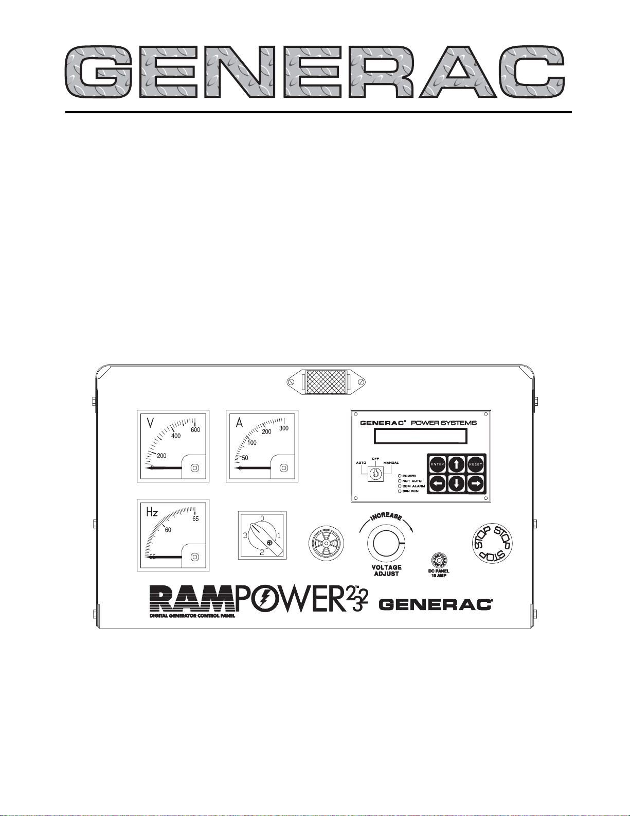
“E” Option Control Panels
This manual should remain with the unit.
This manual contains standard drawings and schematics.
For specific drawings, please refer to the Owner’s Manual of the unit.
Page 2
Generac®Power Systems, Inc.
Important Safety Instructions
E Option Control Panels
SAVE THESE INSTRUCTIONS – The manufacturer suggests that these rules for safe
operation be copied and posted in potential hazard areas. Safety should be stressed to all
operators and potential operators of this equipment.
!
!
Study these SAFETY RULES carefully before
installing, operating or servicing this equipment.
Become familiar with this manual and all literature
pertaining to your generator set and related equipment. This equipment can operate safely, efficiently
and reliably only if it is properly installed, operated
and maintained. Many accidents are caused by failing
to follow simple and fundamental rules or precautions.
Generac cannot possibly anticipate every possible circumstance that might involve a hazard. The warnings in this manual, and on tags and decals
affixed to your equipment are, therefore, not
all-inclusive. If you use a procedure, work method or
operating technique Generac does not specifically recommend, you must satisfy yourself that it is safe for you
and others. You also must make sure the procedure,
work method or operating technique that you choose
does not render the equipment unsafe.
GENERAL HAZARDS
• For safety reasons, Generac recommends that this
equipment be installed and serviced by a Generac
Authorized Service Dealer or other competent, qualified electrician or installation technician who is familiar with applicable codes, standards and regulations.
The operator also must comply with all such codes,
standards and regulations.
• When working on this equipment, remain alert at all
times. Never work on the equipment when you are
physically or mentally fatigued.
• Inspect the equipment regularly, and promptly repair
or replace all worn, damaged or defective parts using
only factory-approved parts.
• Before performing any maintenance on the generator
or any related equipment, disable the generator to
prevent accidental start-up. Remove the control
panel fuse and then disconnect the battery cables by
removing the one indicated by a NEGATIVE, NEG or
(–) first. To re-enable the generator, reconnect the
battery cables connecting the one indicated by a
NEGATIVE, NEG or (–) last, then re-install the control panel fuse.
ELECTRICAL HAZARDS
• Generators produce dangerous electrical voltages
and can cause fatal electrical shock. Avoid contact
with bare wires, terminals, connections, etc., while
the generator and related equipment are running.
Ensure all appropriate covers, guards and barriers
are in place before operating the equipment. If you
must work around an operating unit, stand on an
insulated, dry surface to reduce shock hazard.
• Do not handle any kind of electrical device while
standing in water, while barefoot, or while hands or
feet are wet. DANGEROUS ELECTRICAL SHOCK
MAY RESULT.
• If people must stand on metal or concrete while
installing, operating, servicing, adjusting or repairing
this equipment, place insulative mats over a dry
wooden platform. Work on the equipment only while
standing on such insulative mats.
• Wire gauge sizes of electrical wiring, cables and cord
sets must be adequate to handle the maximum electrical current (ampacity) to which they will be subjected.
• Before installing or servicing this equipment, make
sure that all power voltage supplies are positively
TURNED OFF at their source. Failure to do so will
result in hazardous and possibly fatal electrical
shock.
• When installed with an automatic transfer switch, the
generator may crank and start anytime without
warning. To prevent injuries caused by sudden startup, disable the generator’s automatic start circuit
before working on or around the unit. Then, place a
“Do Not Operate” tag on the generator control panel
and on the transfer switch.
• In case of accident caused by electric shock, immediately shut down the source of electrical power. If
this is not possible, attempt to free the victim from
the live conductor. AVOID DIRECT CONTACT WITH
THE VICTIM. Use a nonconducting implement,
such as a rope or board, to free the victim from the
live conductor. If the victim is unconscious, apply
first aid and get immediate medical help.
• Never wear jewelry when working on this equipment.
Jewelry can conduct electricity resulting in electric
shock, or may get caught in moving components
causing injury.
FIRE HAZARDS
• For fire safety, the generator and related equipment
must be installed and maintained properly.
Installation always must comply with applicable
codes, standards, laws and regulations. Adhere
strictly to local, state and national electrical and
building codes. Comply with regulations the
Occupational Safety and Health Administration
(OSHA) has established. Also, ensure that the
equipment is installed in accordance with the manufacturer’s instructions and recommendations.
Following proper installation, do nothing that
might alter a safe installation and render the unit
in noncompliance with the aforementioned codes,
standards, laws and regulations.
!!
Page 3

Table of Contents
E Option Control Panels
Generac®Power Systems, Inc. 1
Safety Rules ..............Inside Front Cover
Section 1 — General Information..........2
Overview ................................................................2
Engine Control ......................................................2
E Option Control Module ......................................2
Alarms....................................................................4
Alarm Processing....................................................5
Programmable Parameters ....................................6
E Panel Modem Setup Procedure ..........................9
E Panel RS 232 Cables ..........................................9
Additional Panel Components ..............................10
Checking/Replacing the E Panel Control Module
Internal Fuse ....................................................11
User Programmable Inputs ..................................11
Wiring Examples ..................................................12
Programming Examples ......................................13
Section 2 — Operation........................14
Output Function Table ............................................14
E Panel Master Control Box Configuration Settings15
E Panel Display Map ............................................18
Section 3 — Troubleshooting and
Diagnosis ........................20
Oil Pressure Sensing ..............................................20
Low Coolant Level ..................................................22
Coolant Temperature Sensing ................................25
Oil Temperature Sensing ........................................27
AC Voltage Display ..................................................29
RPM Sensor and Engine Speed Alarms ..................29
Engine Does Not Crank ..........................................31
Overcrank................................................................34
Appendix — Phoenix and
Deutsch Connectors ........35
Section 4 — Glossary..........................38
E Control Panel Definitions ....................................38
Section 5 — Electrical Data ................39
E Panel Drawing Application Matrix ......................39
Section 6 — Exploded Views and
Parts Lists ......................60
Section 7 — Notes ..............................76
AUTHORIZED SERVICE DEALER LOCATION
To locate the GENERAC AUTHORIZED SERVICE
DEALER nearest you, please call this number:
1-800-333-1322
DEALER LOCATION INFORMATION
CAN BE OBTAINED AT THIS NUMBER.
Page 4

OVERVIEW
The “E” option control panel is a programmable
engine control and monitoring system. It allows the
user to customize the generator starting and running
sequence, monitor engine parameters and configure
the alarms. This can be done either through its own
control module, featuring liquid-crystal display
(LCD) and keypad, or using a PC and RS232 serial
communications. The module includes user programmable inputs and outputs that allow it to be tailored to a vast range of applications. All of the setup
information is stored in nonvolatile (permanent)
memory.
ENGINE CONTROL
The module has a three-position selector switch that
selects between “Auto” mode, “Off” and “Manual” start
mode. When the switch is in the OFF position, the
generator will not start, and it will stop if it is running.
When the switch is turned to MANUAL, the generator
will start immediately and will continue to run until
the switch is turned to the OFF position or a shutdown alarm is activated. With the switch in the AUTO
position, the generator will wait for either the remote
start contacts to close or for a start command to be
sent from the serial link. The generator will run until
the remote start contacts open, a stop command is
sent down the serial link, a shutdown alarm is activated or the switch is turned to the OFF position. The
remote start contacts always will have priority over
the serial link commands so that the serial link cannot stop the generator if the remote start contacts are
closed. When GenLink®software, which may be
obtained from a Generac Authorized Service Dealer, is
connected to the E panel via modem, the panel will
monitor the connection to ensure that the line has not
dropped. If the E panel detects that the line has been
dropped, it will disconnect the modem so that it is
ready for another incoming call. If the generator had
been started via the modem connection, then it will be
stopped immediately unless the remote start contacts
are closed or the generator is in manual. However, if
the GenLink®software disconnected cleanly (as a
result of a user command) with the generator running,
then the generator will continue to run for a another
three hours unless it receives a stop command.
When a start command is received, the engine preheat
will be engaged, if it is selected. The user can program
the preheat to engage for a programmable time before
engaging the starter motor, to engage while the engine is
attempting to start, or to do both. In order to protect
the engine from trying to start while it is already running (if the rpm sensor is damaged), an alarm is generated if there is oil pressure when the start command is
sent. An alarm also is generated if there is a voltage
output from the generator but the rpm sensor detects
zero engine speed.
The user can program the length of time that the starter
motor is engaged during a start attempt. After the first
attempt, the generator will pause for a programmable
length of time before the next attempt. The number of
attempts also is programmable, after which the failed
to start alarm is activated.
The user can program a warm-up time that is active
after the generator has started. This could be used in
conjunction with a programmable relay output to
inhibit the transfer switch from applying load until
the generator is ready. The warm-up time can be set
to zero if this function is not required. This timer is
separate from the alarm hold off timer, which allows
the generator to run for a time before certain alarms
(such as low oil pressure) are active.
If the generator is in the AUTO mode and a stop command is received, a programmable cool-down timer
can be used to keep the generator running with no
load for a fixed time. This also can work in conjunction with a relay output to inhibit the transfer switch.
If the timer is set to zero, this function is disabled. If
the selector switch is turned to OFF, then the generator will stop immediately without waiting for the cooldown time.
Certain alarm functions are designated as shutdown
alarms. These alarms will stop the generator and
inhibit it from starting until the alarm condition has
cleared and the alarm has been reset.
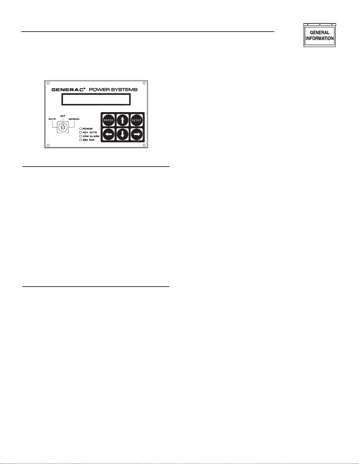
E OPTION CONTROL MODULE
OVERVIEW
The LCD on the front of the module (Figure 1.1) features a 24-character by two-line display screen that will
show one of seven pages. There is a keypad with six
keys that are used for operating the display and selecting the various pages. A key-activated switch allows the
user to select whether the generator is in the “Auto”
mode, “Off” mode or “Manual” run mode. Four LEDs
indicate the following conditions:
• “Power” – Battery power is OK.
• “Not Auto” – The generator is not in the automatic
mode.
• “Com Alarm” – A common alarm condition has
occurred.
• “Gen Run” – The generator is running.
NOTE:
The “Power” LED will go out immediately if the
battery voltage dips below the alarm limit, but the
alarm will not be triggered unless the voltage is
low for more than five minutes.
Section 1 — General Information
E Option Control Panels
2 Generac®Power Systems, Inc.
Page 5
Generac®Power Systems, Inc. 3
Figure 1.1 – Control Module Layout
KEYPAD
The keypad consists of six keys labeled as follows:
↑ (up), ↓ (down), ← (left), → (right)
,
Enter, and Reset.
The left and right arrow keys are used to select the different pages on the display. The up and down arrow
keys are used to scroll between options within a page.
They also are used for selecting characters when the
user is entering messages or parameters for the
alarms. The left and right arrow keys move the cursor
when the user is entering data. The enter key takes the
user into a page on the display to change data (when
applicable) and also accepts data that has been entered.
It also is used to accept an alarm. The reset key ignores
data that has been entered and returns the original
value. It also is used to return from the parameter entry
mode once the user has finished changing the data, and
to reset any latched alarms that have cleared.
DISPLAY
The display is organized into a series of pages, each
page displays information about the status of the generator. For example, the “Alarm Status Message Page”
displays the highest priority current alarm or status
condition. The user will be able to scroll between the
pages using the left and right arrow keys. Certain
actions also cause the display to change pages, e.g.,
when an alarm becomes active, the display automatically will go to the alarm status page and display the
alarm message.
The back light for the display is normally off. If the
user presses any key, the back light will come on
automatically and remain on for five minutes after
the last key was pressed. It also will come on if any
status message is current, which means the display
will switch to the alarm status page. The back light
will flash when an alarm or shutdown message is
active, and the audible alarm will sound.
When the display is showing certain pages, the user
is able to scroll between relevant items within the
page using the up and down arrow keys. For example,
if the display is showing the “Alarm Log Page,” the
user can use the up and down arrow keys to scroll
between the entries on the alarm log. A description of
each page is given below.
Software Version Page
This page displays the software revision. Pressing the
enter key in this page will perform a display and LED
test.
Generator Command Page
This page displays the command sent to the generator. The possible commands are as follows:
• Generator switched off
• Generator in manual mode
• Generator in auto mode – stop command
• Generator in auto mode – remote run command
• Generator in auto mode – serial link run
command
Generator Status Page
This page displays the current status of the generator.
Options will be as follows:
• Stopped – ready to run
• Stopped – start inhibit active
• Pre-heating (with timer counting down)
• Attempting to start (with timer counting down and
number of attempts)
• Pausing before start attempt (with timer counting
down and number of attempts)
• Started – running up to speed
• Warming up
• Ready to accept load
• All alarms enabled
• Cooling down
• Stopping
• Stopped due to alarm
If the user has not pressed a key for some time, any
change in status will cause this page to be displayed
provided that there are no active alarms or status
messages from other inputs. If an alarm condition
occurs, the alarm status page will be displayed automatically.
Alarm Status Message Page
This page displays alarm messages and programmable status messages. Messages are displayed
according to priority, with the shutdown alarms
having highest priority, and status messages having
lowest priority.
Section 1 — General Information
E Option Control Panels
Page 6

4 Generac®Power Systems, Inc.
If an alarm becomes active, the display will switch to
this page and display the highest priority alarm message. The back light and alarm LED will flash, and the
audible alarm will be activated. The user must press
the enter key to accept the alarm, at which time the
back light will be on continuously. If the alarm is nonlatching, the alarm message will clear as soon as the
condition is cleared. If the alarm is a latching alarm,
then the user must press the reset key to clear the message. Once a message has cleared, the display will show
the next priority alarm message.
After an alarm has been accepted, the user is able to
scroll through other active alarm and message
screens using the up and down arrow keys.
Alarm Log Page
This page displays the last 50 alarm messages. When
the user selects this page, it displays the latest alarm
message. Pressing the up or down arrow keys will
allow the user to scroll up and down the list of messages.
Instrumentation Page
This page displays one of the analog signal values.
Pressing the up or down arrow keys will scroll to
other analog display screens.
Parameter Entry Page
This page allows the user to modify the various set
points and programmable options. See the
“Programmable Parameters” section of this manual
for more specific option information. The user must
press the Enter key when this page is displayed and
will then be prompted for a password. The password
is a six-digit number and the default value is 000000.
However, the user will be able to change the password. Digits will be selected using up and down
arrow keys, and the cursor will be moved by the left
and right arrow keys. When the user presses the
Enter key, the password will be checked. If the password is correct, the display will show one of the data
entry screens.
There are four parameter entry menus: “Engine
Parameter,” “System Alarm,” “Digital I/O” and “Analog
Input.” The user will be able to scroll through the various parameters in each menu using the up and down
arrow keys. The left and right arrow keys are used to
switch between the four menus. When a parameter that
requires changing is displayed, the user presses the
Enter key to enable data entry. A cursor will appear at
the first character that can be altered. The user can
then change the character using the up and down arrow
keys. The user can move to the next character or previous character using the left and right arrow keys.
Pressing the Enter key will accept the new setting.
Pressing the Reset key will ignore the new setting.
If an alarm condition occurs when the user is entering data, the data will be ignored, and the display will
show the alarm screen. If a status condition occurs
when data is being entered, the display will not
change.
Once the user has finished entering data by pressing
the Enter key, pressing the Reset key will allow the
user to select other pages using the left and right
arrow keys.
ALARMS
All analog channels have alarms associated with
them. There is also a coolant level alarm, an emergency stop alarm and eight user definable inputs that
can be used to generate alarms. Alarms can be status
messages, non-latching alarms, latching alarms or
shutdown alarms. When a new alarm condition
occurs, the alarm LED and the display back light will
flash. Also, the alarm relay contacts will close (operating the audible alarm), and the display will show
the alarm message. The user will be able to accept the
alarm (turn off the audible alarm) from the keypad,
and if the alarm condition has cleared, he or she also
will be able to clear the alarm. Non-latching alarms
will clear themselves if the alarm condition is no
longer present. Latching alarms require the user to
clear the alarm from the keypad even if the alarm
condition is no longer present. Shutdown alarms are
similar to latched alarms, but they also cause the
generator to stop and will not allow it to start again
until the key-switch has been turned to the OFF position to reset the alarm. Status messages are similar
to non-latching alarms except that they do not activate the alarm relay or the alarm LED and are not
recorded on the alarm log.
Alarms can be always active, immediately active when
the generator is commanded to run, or active after
the hold off timer has expired. This timer delays the
operation of certain alarms until a programmable
time after the engine has started. Some alarms allow
the user to define the type of alarm and when it is
active.
The following chart is a summary of the alarms and
the programmable options:
Section 1 — General Information
E Option Control Panels
Page 7

Generac®Power Systems, Inc. 5
ALARM PROCESSING
INPUT ALARM FUNCTIONS
The E option panel will monitor the status of the analog and digital inputs, and generate alarm messages
as required. Digital alarms and user-defined analog
alarms are fully programmable. The user is able to
select the type of alarm, the state of the input that will
trigger the alarm, and the alarm message when it is
active. The configurations are defined as follows:
Alarm Active
The user is able to select when the alarm is active.
The options will be as follows:
• Disabled: If this option is selected, the alarm is
disabled and has no effect.
• Always: With this option selected, the alarm is
active regardless of the state of the generator.
• Immediate: In this mode, the alarm is not active
when the generator is stationary. It becomes active
as soon as the generator starts to crank and
remains active until the generator stops.
• Hold Off: This option waits until a preset time
after the generator is running before becoming
active. The hold off time can be set by the user.
Note that the hold off time is common to
all alarms.
Section 1 — General Information
E Option Control Panels
Alarm Message Alarm Active Options Alarm Type Options
Pre-Low Oil Pressure Warning Hold Off Non-Latch
Low Oil Pressure Shutdown Alarm Hold Off Shutdown
Pre-High Coolant Temp. Warning Hold Off Non-Latch
High Coolant Temp. Shutdown Alarm Hold Off Shutdown
Low Coolant Temp.Warning Always Non-Latch
Pre-High Oil Temp. Warning Immediate, Hold Off, Disabled Non-Latch
High Oil Temp. Shutdown Alarm Immediate, Hold Off, Disabled Shutdown
Low Battery Voltage Warning* Always Non-Latch
Overspeed Alarm Immediate Shutdown
Underspeed Hold Off Status, Non-Latch, Latch, or Shutdown
Overcrank Alarm Immediate Shutdown
Over Voltage Hold Off Status, Non-Latch, Latch, or Shutdown
Under Voltage Hold Off Status, Non-Latch, Latch, or Shutdown
Over Frequency Hold Off Status, Non-Latch, Latch, or Shutdown
Under Frequency Hold Off Status, Non-Latch, Latch, or Shutdown
High Fuel Warning Always, Disabled Non-Latch
Low Fuel Warning Always, Disabled Non-Latch
Low Fuel Shutdown Alarm Always, Disabled Shutdown
User Analog Alarms** All Options Available All Options Available
Low Coolant Level Alarm Hold Off Shutdown
Emergency Stop Always Shutdown
RPM Sensor Failure Alarm Always Shutdown
Start Inhibit – Oil Pressure Immediate Shutdown
Oil Pressure Sensor Failure Always Shutdown
Oil Temp.Sensor Failure Always, Disabled Shutdown
Coolant Temp.Sensor Failure Always Shutdown
User Digital Input Alarms*** All Options Available All Options Available
High Battery Voltage Warning Always Non-Latch
* Battery voltage must be below alarm limit for 5 minutes to trigger alarm.
** Each user analog input channel has a high and low alarm.
*** Each user digital input can be programmed to trigger an alarm on high or low level.
Page 8

6 Generac®Power Systems, Inc.
ALARM TYPE
Status
This type of alarm will display a message on the
screen. The message will not be logged. This is the
lowest priority of alarm types.
Warning – Non-Latched
This type of warning will activate the audible alarm,
and flash the alarm LED and display back light. The
associated message will be displayed on the screen.
When the user accepts the warning (by pressing the
Enter key), the back light will stop flashing, and the
alarm LED will be on continuously. The message will be
displayed on the alarm screen, but the user will be able
to scroll through other screens. The LED and message
will clear when the warning condition clears. This type
of warning is logged.
Alarm – Latched
This type of alarm will act similarly to the non-latched
warning, except that the alarm does not clear when the
alarm condition clears. When the alarm condition
occurs, the audible alarm sounds, the LED and back
light flash as before, and the user must accept the
alarm to stop them. The alarm will continue to be displayed on the screen even after the alarm condition has
cleared. The user must either press the Reset key or
turn the key-switch to the OFF position to clear the
alarm after the alarm condition has cleared. This type
of alarm is logged.
Shutdown
This type of alarm will act similar to the latched
alarm, but it also will stop the engine when the alarm
condition occurs. It can be reset only by turning the
key-switch to the OFF position. All shutdown alarms
are latching, and this type of alarm is logged.
Alarm Status
This is the value at which the alarm is active. For analog alarms, it is a number corresponding to the alarm
limit. Digital alarms are either “normally open” or
“normally closed,” and an alarm is generated when
the input is not in the normal state.
Alarm Message
Each alarm will have a message associated with it. The
analog alarm messages will be preset, and the digital
alarm messages and user-defined analog messages will
be entered via the keypad or the serial link.
OTHER ALARMS
Overcrank
This alarm is unlike other alarms as it is not associated with an analog or digital signal. The user is able
to define the number of crank attempts, the length of
each crank attempt and the rest time between
cranks. After the last attempt has been made, an
overcrank alarm will be generated. The user must
turn the key-switch to the OFF position to clear the
alarm.
Coolant Level
This alarm is generated by the coolant level detector.
This device senses whether coolant is present or not.
It has no user-definable level setting and is a shutdown alarm that is active after the hold off time.
There are no user-definable parameters for this
alarm.
PROGRAMMABLE PARAMETERS
The E option panel allows the user to configure various options to control the generator starting and
stopping cycles, and the way that the alarms operate.
Parameters are entered either from the control module or via the serial link. A description of the programmable parameters follows:
PREHEAT ENABLED
This parameter determines how the preheat function
works. The preheat can be fully disabled, enabled
before starting only (for the duration of the preheat
time), or before and during starting (for the duration
of the preheat time and also while the starter is
engaged). Note that if the user wishes to engage the
preheat during starting but not to have a preheat
before starting, it is possible to set the preheat time
to zero.
PREHEAT TIME
When a start command is received, some engines
require preheating before the generator attempts to
start. When the preheat function is enabled, this
parameter allows the user to determine the time that
the preheat contact closes before activating the
starter solenoid.
START TIME
Once a start command has been received and
the preheat time has expired (if enabled), the starter
solenoid will be engaged. This parameter allows the
user to determine how long the starter solenoid is
engaged before the start attempt is regarded as having failed. If the generator does not start within this
time, the generator will wait for a preset time before
attempting to start again. The user also can program
the number of start attempts the generator tries.
Section 1 — General Information
E Option Control Panels
Page 9

Generac®Power Systems, Inc. 7
PAUSE TIME
If the generator does not start within the programmed start time, it will pause before trying to
start again. This parameter determines the length of
that pause.
START ATTEMPTS
This parameter determines the number of times that
the generator tries to start. If the generator has not
started after this number of attempts, an alarm is
generated.
STARTER DISENGAGE SPEED
While the starter is engaged, the engine speed is monitored. Once it reaches this value, the starter motor is
disengaged, and the engine is regarded as having
started.
HOLD OFF TIME
Once the engine has started, some alarm functions
(such as low oil pressure and under speed) are not
activated immediately since the engine must be given
time to reach a stable condition. This parameter
determines the time that elapses before the hold off
alarms are activated.
COOL-DOWN TIME
It is sometimes desirable to run the generator for a
given time with no load before stopping to allow the
engine to cool down. This parameter determines the
length of time that the generator continues to run
after a stop command is sent in AUTO mode. Note
that if the key-switch is turned to the OFF position
when the generator is running, it will stop immediately regardless of this setting. This value also should
be set to zero if this function is controlled by the
transfer switch.
LOAD ACCEPT VOLTAGE AND FREQUENCY
Once the generator has started, the voltage and frequency will ramp up until they reach the values at
which the generator can accept load. These parameters allow the user to set the values. The values
should be set slightly lower than the nominal values
to allow for a margin of error in the regulator and
governor settings. Once the values have been
reached, the warm-up timer is started.
WARM-UP TIME
Some applications require that the generator is
allowed to run for a given time before a load is
applied. This parameter allows the user to set that
time. Note that if this function is controlled elsewhere
(e.g., within a transfer switch), this time should be set
to zero. The generator is ready to accept load when
this timer expires. This parameter can be assigned to
an output relay.
VOLTAGE SCALING FACTOR
The voltage scaling factor is used to scale the sensing
voltage applied to CON4-4 and CON4-6.
On generators manufactured prior to the second
quarter of 2000: Sensing voltage was measured from
line-to-line, so the scaling factor was primarily set to
1.0. On generators manufactured starting the second
quarter of 2000: Sensing voltage is measured from
the frequency meter, in this case the scaling factor is
used so the “E” panel displays line-to-line voltage.
This scaling factor can also be used to “calibrate” the
“E” panel display.
FLYWHEEL TEETH
This parameter holds the number of flywheel teeth.
This value is used to determine the engine speed
from the magnetic pickup signal.
USER-DEFINED OUTPUT FUNCTIONS
There are three user-defined outputs, and the preheat
output also can be used as a user-defined output if the
preheat function is disabled. Each output can be programmed to signal that an alarm is active, to indicate
one specific alarm or input condition, to indicate the
status of the key-switch, or to indicate the current status of the generator. These relay contacts can be used
to switch up to 30 volts AC or DC at 1 amp.
Programming example for user output #2 to be active
on any generator alarm shutdown:
1. Press the left or right arrow key until the display
reads “Parameter entry” and press ENTER.
2. Enter your password and press ENTER.
3. Use the left and right arrow keys to find the
“Digital I/O Menu”.
4. Use the up and down arrow keys to locate “Output
2 Function”. The bottom line of the display will
read the current setting. Press ENTER.
5. Use the up and down arrows to scroll through the
list until “Generator Alarm Shutdown” is displayed in the bottom line. Press ENTER.
6. User output #2 is now programmed to become
active (relay energized) on any generator shutdown
alarm.
7. Press RESET. This exits the programming mode
and returns you back to the parameter entry
screen.
NOTE:
See the “Output Function Table” on Page 14 and
the “E” Panel Display Map on pages 18-19 for
more detail.
Section 1 — General Information
E Option Control Panels
Page 10

8 Generac®Power Systems, Inc.
ANALOG INPUT SCALING FACTORS
The two user-defined analog inputs can be scaled so
that the display uses meaningful values rather than the
voltage level at the input. The user enters the value to
be displayed when the input voltage is zero and when it
is at the maximum value. (An analog input to the E
panel is a voltage sourced input with a zero- to 10-volt
range.) All alarm settings are based on this scaling, and
the instrumentation display shows the input value
based on this scaling too.
ANALOG INPUT MESSAGES
This is a message up to 24 characters long that is displayed on the instrumentation display when the corresponding value is being shown.
ANALOG INPUT ALARM MESSAGES
There is a user-definable message for each alarm
condition on each analog input. This message is
shown on the alarm display when the alarm condition is active and is stored in the alarm log.
ANALOG INPUT ALARM SETTINGS
Each analog input has two alarms associated with it.
One is activated when the input value is higher than
the high set-point, and the other is active when the
input is lower than the low set-point. The user also
can define when the alarm is active (or disable it) and
the severity of the alarm (from simply displaying a
status message to shutting down the generator – see
“Alarm Processing” on Page 5).
DIGITAL INPUT ALARM SETTINGS
Each digital input also can generate an alarm. The
user can program the alarm message, the input state
that generates the alarm, when the alarm is active,
and the alarm type. A digital input to the E panel is
NOT a voltage sourced input, but a dry contact closure to ground. Voltage never should be sourced to a
digital input. The signal options to a digital input are
as follows:
• Open: This signal is an open circuit.
• Closed: This signal is a contact closure to ground.
OIL PRESSURE ALARMS
The oil pressure input has two associated alarm
functions. The pre-low oil pressure warning is a nonlatched, hold off alarm with a user-definable setpoint. The low oil pressure shutdown is a shutdown,
hold off alarm with a user-definable set-point. The
shutdown alarm set-point should be the lowest of the
two settings so that the user will have some warning
of a low oil condition before the generator is shut
down.
OIL TEMPERATURE ALARMS
The oil temperature has a non-latched warning and a
shutdown alarm associated with it. The set-points are
programmable, and the alarms can be immediate,
hold off or disabled.
COOLANT TEMPERATURE ALARMS
The coolant temperature input has three associated
alarms. The pre-high coolant temperature alarm is a
non-latched, hold-off alarm. The high coolant temperature alarm is a shutdown, hold-off alarm. The
low coolant temperature warning is a non-latched,
always active alarm. Set-points for each alarm are
programmable.
BATTERY VOLTAGE ALARMS
The low battery voltage warning set-point is programmable. The warning will be activated if the battery voltage is below this value for more than five
minutes. This is a non-latched, always active alarm.
Note that the “Power” LED on the front panel is extinguished immediately if the battery voltage is less than
this value. The high battery voltage alarm set-point is
also programmable. The warning is active immediately when the battery voltage is higher than this
value.
ENGINE SPEED ALARMS
The user can program the overspeed and the underspeed alarm. The overspeed alarm is an immediate
shutdown alarm. Underspeed is a hold off alarm that
can either be non-latched, latched or shutdown.
GENERATOR VOLTAGE ALARMS
An alarm can be generated for high voltage and low
voltage. The set-points are user-definable, and the
alarms can be either non-latching, latching or shutdown.
GENERATOR FREQUENCY ALARMS
An alarm can be generated for high frequency and
low frequency. The set-points are user-definable, and
the alarms can be either non-latching, latching or
shutdown.
FUEL LEVEL ALARMS
Alarms can be generated by an optional fuel level sensor. The high fuel level warning is non-latching. There
is also a low fuel level warning that is non-latching
and a low fuel shutdown alarm. Each of these alarms
has a set-point and can be always active or disabled.
Section 1 — General Information
E Option Control Panels
Page 11
Generac®Power Systems, Inc. 9
E PANEL MODEM SETUP PROCEDURE
NOTE:
Generac only supports the US Robotics 56k V90
Sportster modem for connection of the “E” Panel
to the phone line. Other modems may work in this
application, but have not been tested by Generac.
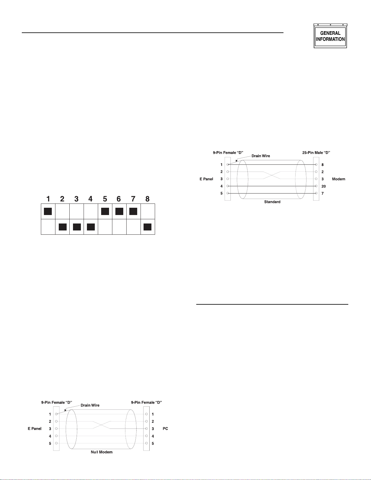
1. Set modem Dip switches as shown in Figure 1.2.
Power cycle the modem (turn modem off, then on).
2. Connect the cable between the “E” panel and the
modem (see Figure 1.4).
3. Set the “E” panel for “modem connection and
setup”. Power cycle the “E” panel (remove and
relace front panel fuse).
4. In GenLink, select the proper setup string for the
modem at the PC end (not the “E” panel).
Figure 1.2 — US Robotics 56k V90 Sportster
Dip Switch Settings
E PANEL RS232 CABLES
The “E” panel can communicate via its RS232 port to
a remote PC. The connection is made either directly
to the serial port on a PC, or via a modem and telephone line.
The “E” panel has a 9-pin male “D” type connector,
and is configured as DTE (Data Terminal
Equipment). The serial ports on most PCs also have
a DTE configuration, and are usually 9-pin “D” type
male connectors. Most modems have a DCE configuration (Data Communication Equipment) and a 25pin female connector.
Connecting an “E” panel directly to a PC requires a
“Null Modem” connection. This can be achieved with
either a null modem cable, or a standard serial cable
with a null modem adapter. Figure 1.3 shows the
required pin connections between the two cables for
a 9-pin serial connector on the PC.
Figure 1.3 — “E” Panel to PC Cable
Configuration
NOTE:
Use shielded cable, 100 feet maximum in length.
Connect the shield drain wire to Pin 1 on the E
panel end only.
Connecting the “E” panel to a modem requires a standard modem cable. The cable supplied with the
modem should work. If a longer cable is required, the
connectors should be wired as shown in Figure 4.
Figure 1.4 — “E” Panel to Modem Cable
Configuration
NOTE:
The modem is not intended to be mounted inside
the control panel. It should be mounted inside the
enclosure (no vibration) or inside a nearby building or shelter if the generator does not have an
enclosure.
NOTE:
Use shielded cable, 100 feet maximum in length.
Connect the shield drain wire to Pin 1 on the E
panel end only.
SERIAL COMMUNICATIONS
Serial Communication Via Modem
(Also refer to the appropriate Genlink Manual)
The control panel has the ability to communicate to a
PC via an RS232 serial port. The PC software will be
able to interrogate the module. The user also will be
able to program the parameters on the PC and download them to the module if using the Pro version. The
user will be able to start and stop the generator if it is
in AUTO mode.
The module does not have a built-in modem.
However, software will include the ability to interface
with an external modem. The user can initialize the
modem from the panel. Generac offers a remote
annunciator (models #’s 004391-0, 004392-0 and
004391-1, 004392-1) which allows the E panel to
communicate with both a modem and a remote
annunciator. See the Remote Annunciator Panel manual (part number 0A7450) for a complete description
of these panels.
Section 1 — General Information
E Option Control Panels
Page 12
10 Generac®Power Systems, Inc.
Section 1 — General Information
E Option Control Panels
Remote Annunciator Panel
(Refer to manuals 0A7450 and 0A9825)
The serial connections can be configured to allow the
control panel to connect to a remote
annunciator/remote relay panel, which is configured
as RS485, to meet NFPA 110. Only one communication port is available for either a modem or remote
annunciator.
NOTE:
The following diagram and instructions apply only
to those units manufactured before January 2000.
Units manufactured after January 2000 incorporate a selector switch on the back of the control
module. This switch will allow selection of either
RS232 or RS485 without opening the module.
Altering the Serial Communications Setup
The E option control panel is capable of being used
with either a modem or a remote annunciator/
remote relay panel, depending on the configuration of
the serial connections. The unit comes set up for connection to a modem (RS232). In order to use the control panel with a remote annunciator/remote relay
panel (RS485), adhere to Figure 1.5 and the instructions that follow.
1. Remove harness retaining screws, then unplug all
five wire harnesses from the back of the E panel
control module.
2. Remove the four phillips head screws retaining the
rear cover of the control module.
3. Open the back of the control module.
4. Locate the DB-9 wire harness that runs from the
DB-9 connector on the back panel to the black
header on the lower circuit board inside the control module.
5. Carefully remove the black connector from
the header by pressing the locking tab and
lifting up.
6. Insert the black connector into the RS485
header (J11). Make sure that the connector is fully
inserted and that the locking tab snaps into place.
7. Replace the back panel and the four screws.
Figure 1.5 – E Panel Serial Communications
Setup Modification
USER PASSWORD
The user can set the password. This is a six-digit
number and is initially set to 000000.
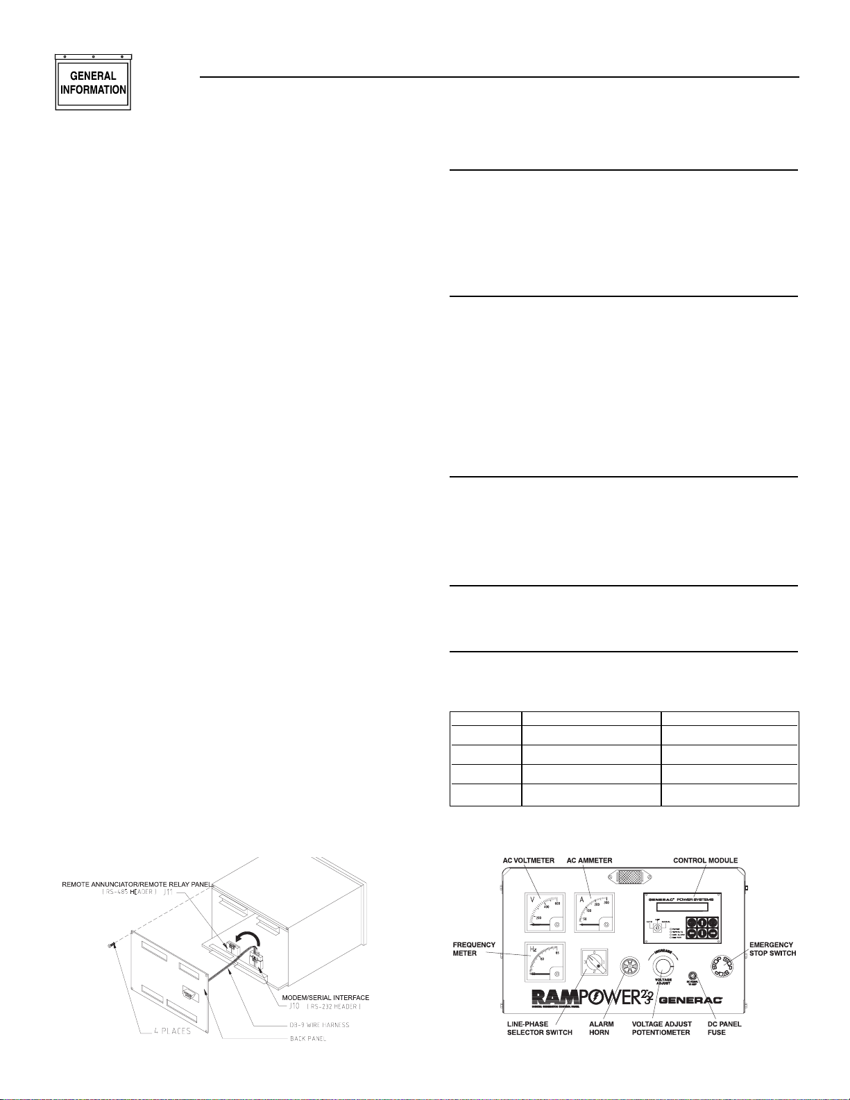
ADDITIONAL PANEL COMPONENTS
In addition to the control module, the E option panel
contains the following components (see Figure 1.6):
AC VOLTMETER
This meter indicates the generator AC output voltage.
To determine the nominal rated AC voltage of the
unit, refer to the unit’s data plate.
NOTE:
Some generators are re-connectable to a variety of
voltages. Some units may be equipped with a
rotary “Voltage Selector Switch.” Be sure to read
the “Generator AC Lead Connections” section in
the Owner’s Manual.
AC AMMETER
This meter indicates the current draw of connected
electrical loads, in amps. Also see “Line-phase
Selector Switch.” For continuous operation, never
exceed the rated maximum continuous current
capacity of the generator.
FREQUENCY METER
This meter indicates the generator’s AC output frequency in “Hertz” (cycles per second).
LINE-PHASE SELECTOR SWITCH
This four-position switch permits selection of either
line-to-line or line-to-neutral readings on the panel voltmeter and ammeter. Switch positions are as follows:
Figure 1.6 – E Option Panel Components
Switch Single-phase Units Three-phase units
1 Line E1 to Neutral Line E1 to E2
2 Line E3 to Neutral Line E2 to E3
3 Line E1 to E3 Line E3 to E1
OFF No Reading No Reading
Page 13

Generac®Power Systems, Inc. 11
VOLTAGE ADJUST POTENTIOMETER
This potentiometer permits the operator to “fine
adjust” the generator’s AC output voltage on units
rated below 400 kW. Adjustment range is plus or
minus five percent. Turn the knob clockwise to
increase voltage, counterclockwise to decrease voltage.
ALARM HORN
This horn sounds an audible warning when an alarm
condition exists. See the “Alarms” section for further
information.
DC PANEL FUSE
This 15-amp fuse protects the panel components.
This fuse is not to be confused with the control module internal fuse discussed in “Checking/Replacing
the E Panel Control Module Internal Fuse.”
EMERGENCY STOP SWITCH
When pressed, this switch will automatically shut
down the entire generator set. The operator must pull
the switch out to its original position to reset it and
allow for generator operation.
CHECKING/REPLACING THE E PANEL
CONTROL MODULE INTERNAL FUSE
Typically, the main indication of fuse failure is the
absence of any illuminated front panel LEDs (even
with the key in the OFF position, the “Power” LED
will be illuminated) and no text visible on the module
display. It should be noted however, that these conditions can exist if either:
a. The generator start battery is dead (less than five
volts) or disconnected.
b. The main panel fuse (15 amp) is blown.
c. The battery supply wires (#13 and #0) to the
panel control module are open circuit (disconnected).
d. The “Power” connector (CON4) is disconnected
from the rear of the control module.
e. The generator start battery connections have been
reversed. Reversal of the battery connections
WILL blow the internal fuse and is the most likely reason for its failure.
Before removing or disconnecting the E panel control
module, check that none of the above conditions (ae) exist.
If you are satisfied that the problem lies with the
control module:
1. Disconnect the generator start battery.
2. Unplug all four wire harnesses from the back of
the control module.
3. Loosen, then detach, the two retaining clips securing the control module and remove the module.
4. Using a multimeter (e.g., Fluke 87) set to the diode
range, measure between pins 1 (BAT+) and 2 (BAT) of connector CON4 on the module.
• With the positive meter lead connected to pin
2 and the negative lead to pin 1, the meter
should read between 0.4 and 0.6 volts, which
indicates that the internal fuse is OK.
• Reversing the meter leads would give a slowly
increasing voltage reading on the meter, which
also indicates a good fuse.
• An open circuit fuse will give an open circuit
meter reading (.OL on Fluke 87).
If the meter reads open circuit:
5. Remove the four phillips head screws retaining the
rear cover of the control module.
3. Open the back of the control module.
4. Locate the internal printed-circuit board mounted
fuse, which is behind and to the left of CON4.
5. Remove the white plastic cover from the fuse holder and remove the fuse.
6. If the fuse has blown, replace the fuse (part
#0A5705), reassemble the control module, and
reinstall the control module and its connections.
7. Reconnect the generator start battery and check if
the control module now functions.
If the fuse blows again, or was not blown when the
module was opened, or the module still does not
function, the E panel control module must be
replaced.
USER PROGRAMMABLE INPUTS
The E panel has eight (8) user programmable inputs.
These inputs can be used for annunciation, prealarm, or shutdown alarms. Four of the inputs,
Battery Charge Fail, Gen Power, Line Power, and
Programmable Input 4 are set up to annunciate on
the control panel display and at the optional 20 Light
Remote Annunciator (Programmable Input 4 will
light the unlabeled “spare” LED). These four inputs
can be used for other connections if a remote annunciator is not used. The other four inputs, if utilized,
will annunciate at the control panel only.
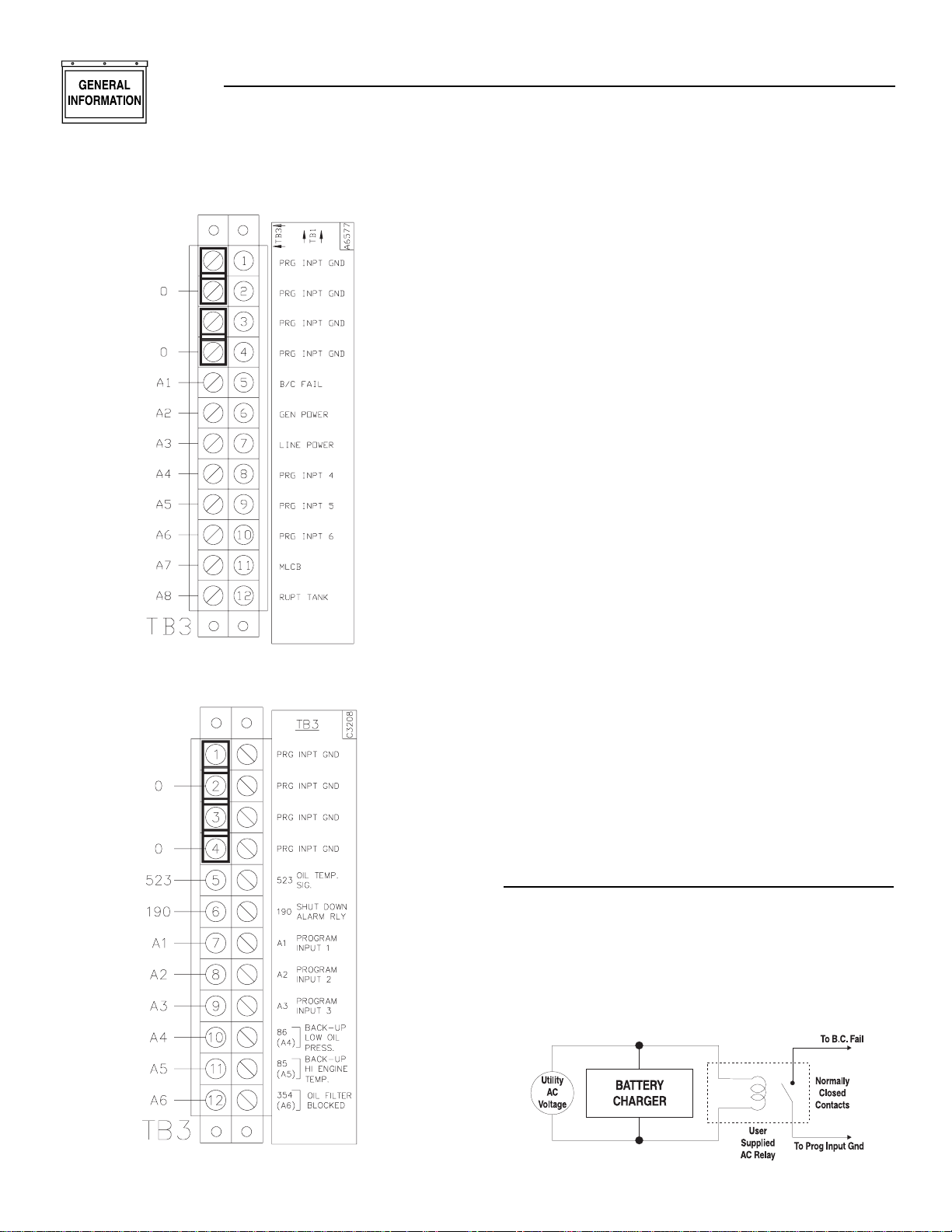
The user programmable input connection points are
located inside the E option control panel on a 12position strip labeled TB3 (refer to Figures 1.7 and
1.8 on page 12.). The first four terminals are labeled
“prog input gnd”. These are the common ground connection points for the user supplied switch devices to
be used for the programmable annunciation.
NOTE:
These ground terminals are for user programmable input use only. The are not to be used for
grounding any other circuits.
Section 1 — General Information
E Option Control Panels
Page 14
12 Generac®Power Systems, Inc.
Figure 1.7 — TB3 Units Up to 400 kW
Figure 1.8 — TB3 Units Over 400 kW
The remaining eight terminals on TB3 are for the “positive” side of each user programmable input switch circuit. These eight terminals have a five VDC potential
available in an open-circuit condition (whether the
control panel key switch is in the off, manual, or auto
position). The inputs can be programmed to annunciate upon either an open circuit condition (five VDC
potential at the terminal) or a grounded condition
(zero VDC potential at the terminal). This voltage state
is determined by the user supplied switch either opening or closing to cause an annunciation.
Program set-up for the user programmable inputs is
carried out in the Digital I/O Menu of the E module
(please refer to the Display Map on pages 18-19). Each
of the eight inputs has four parameters in which specific options must be selected to make the annunciation function properly. These four parameters are
labeled Input Channel Message, Input Channel Setting,
Input Channel Alarm Enable, and Input Channel
Alarm Type. Following is a brief description of each:
• Input Channel Message — for selecting letters and
numbers to spell out what the display will read
upon activation of that specific input.
• Input Channel Setting — for selecting whether
annunciation should activate upon that specific
circuit opening or closing to ground.
• Input Channel Alarm Enable — for enabling or dis-
abling annunciation function of that specific input.
Also, if enabled, for selecting when annunciation
will be active. The choices are: Disabled, Always,
Immediate and Hold-off. See E Control Panel
Definitions on page 38.
• Input Channel Alarm Type — for selecting the type
of alarm annunciation and the effect it has on the
generators control system. The four choices are:
Status, Non-latched, Latched and Shutdown. See
E Control Panel Definitions on page 14.
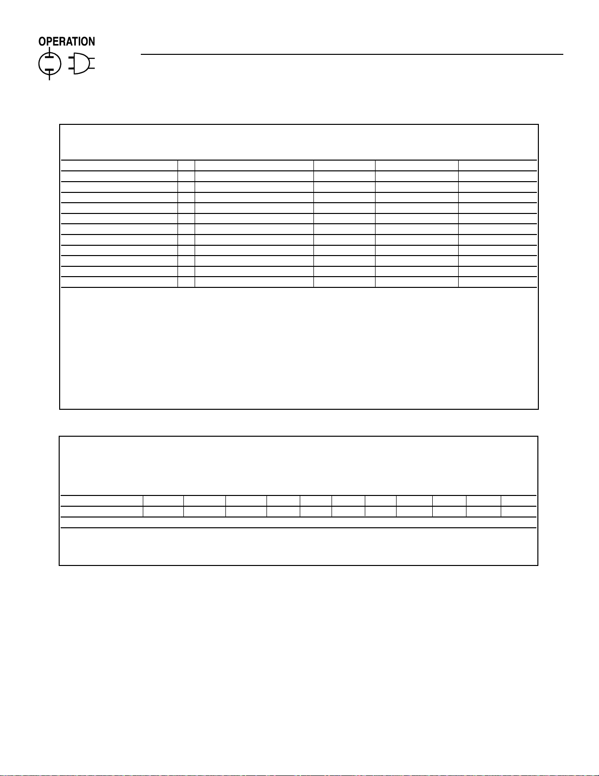
WIRING EXAMPLES
USER PROGRAMMABLE INPUT NUMBER 1
On units rated below 400 kW, input number 1 is programmed for “Battery Charge Fail” annunciation at
the control panel display, and the LED on the 20 Light
Remote Annunciator (if used). A user supplied AC
relay is wired in to be powered up by AC voltage that
supplies the unit Battery Charger (see Figure 1.9).
Figure 1.9 — Battery Charge Fail Wiring
◆
Section 1 — General Information
E Option Control Panels
Page 15

Generac®Power Systems, Inc. 13
Upon loss of this AC supply voltage, the relay will deenergize. The normally closed contacts on the relay
are to be connected to TB3 in the control panel. One
wire connects to any of the four “Prog Input Gnd”
terminals, the other wire connects to terminal number 5 (B/C Fail). With the relay de-energized, terminal
5 will be grounded, signaling the E module to activate
on Programmable Input 1.
USER PROGRAMMABLE INPUTS NUMBERS
2 AND 3
On units rated below 400 kW, input numbers 2 and 3
are programmed for “Gen Power” and “Line Power”
respectively, indicating the transfer switch position
(Standby or Utility). Annunciation will occur at the
control panel display and at the Remote Annunciator
(if used). These signals will come from a set of spare
auxiliary contacts located on the main contactor
assembly in the transfer switch. The auxiliary contact
switch is a set of dry contacts with three terminals:
Common, Normally Open, and Normally Closed.
Wires must be connected to these three terminals and
routed to the generator control panel. These three
wires must not be run in the same conduit as the generator’s main output conductors. The wire connected
to the Common terminal on the auxiliary contacts
will connect to any of the Prog Input Gnd terminals
on TB3. The wire connected to the Normally Open
terminal on the auxiliary contacts will connect to terminal 6 (Gen Power) on TB3. The wire connected to
the Normally Closed terminal on the auxiliary contacts will connect to terminal 7 (Line Power) on TB3.
ALL USER PROGRAMMABLE INPUTS
On units rated below 400 kW, input numbers 4
through 8, and units rated over 400 kW, input numbers 1 through 8 can be used for virtually any kind of
annunciation the user wishes to set up, within the
parameters previously described, via an opened or
closed switch device. Proper wiring consists of two
wires from the user supplied switch: one wire connects to one of the “Prg Inpt Gnd” terminals (1
through 4 on TB3), the other wire connects to a
Programmable Input terminal on TB3.
PROGRAMMING EXAMPLES
USER PROGRAMMABLE INPUT NUMBER 1
To be used for Battery Charge Fail annunciation.
After properly wiring the circuit as described in
Wiring Examples, program as follows:
1. Power up the E panel by connecting unit battery
(ies) and inserting control panel fuse. The module
will run through a self-test mode. Once it has completed its self-test, it will display the generator status (Stopped, ready to run).
2. Use the LEFT or RIGHT arrow keys to scroll over
to the PARAMETER ENTRY column.
3. Once at the PARAMETER ENTRY column, press
ENTER. Enter the password (if different from the
factory set password 000000) and press ENTER.
From the ENGINE PARAMETER MENU, press the
RIGHT arrow to get to the DIGITAL I/O MENU.
4. Using the UP or DOWN arrows (the column is a
continuous loop), scroll to INPUT CHANNEL 1
MESSAGE and press ENTER. Up to 24 letters,
numbers and other characters can be entered to
spell out what will be displayed upon this input
becoming active. In this case, enter Battery Charge
Fail. After entering the message, press ENTER.
5. Press the UP arrow to display INPUT CHANNEL 1
SETTING. Press ENTER, the display will read
Input Function, OPEN=ALARM. The Battery
Charge Fail annunciation should occur upon the
user supplied relay de-energizing and its normally-closed contact closing, therefore, select
CLOSED=ALARM by pressing the UP or DOWN
arrow. Press ENTER, the display will read Input
Channel 1 Setting, CLOSED=ALARM.
6. Press the UP arrow, the display will read Input 1
Alarm Enable, DISABLED, press ENTER. The
choices are DISABLED, ALWAYS, IMMEDIATE,
and HOLD OFF. This alarm should always be
active, therefore, scroll up or down and select
ALWAYS, and press ENTER.
7. Press the UP arrow, the display will read Input
Channel 1 Alarm Type, STATUS MESSAGE, press
ENTER. The choices are STATUS MESSAGE,
NON LATCHING ALARM, LATCHING ALARM and
SHUTDOWN ALARM. This annunciation for
Battery Charge Fail should be a STATUS message,
therefore, scroll up or down and select STATUS
MESSAGE by pressing ENTER.
Programming for User Input Channel 1, Battery
Charge Fail is now complete. The E module has been
programmed for a STATUS alarm message that is
ALWAYS active. Upon loss of AC supply voltage to the
generators battery charger, the user supplied relay
will de-energize, its normally closed contacts will
close, grounding TB3 terminal 5 to Prg Input Gnd.
The E module will display BATTERY CHARGE FAIL.
Because it was programmed as a STATUS alarm and
not a LATCHING or SHUTDOWN alarm, the status
message will clear when AC power is restored to the
battery charger.
NOTE:
The Battery Charger Fail LED on the 20 Light
Remote Annunciator (if connected) will also turn
on when Input Channel 1 is activated.
◆
◆
◆
Section 1 — General Information
E Option Control Panels
Page 16

14 Generac®Power Systems, Inc.
Section 2 — Operation
E Option Control Panels
Output Function Name Description
Function ID
00 Output Disabled Output not in use
01 Common Alarm Active for all latched, non-latched and shutdown alarms
02 Low Oil Pressure Warning Active after hold off time
03 Oil Pressure Shutdown Active after hold off time, low oil pressure
04 High Coolant Temp. Warning Active after hold off time
05 Coolant Temp. Shutdown Active after hold off time, high coolant temperature
06 Low Coolant Temp. Alarm
07 High Oil Temp. Warning
08 Oil Temp. Shutdown High oil temperature
09 Low Battery Voltage Must be below set value for five minutes
10 High Battery Voltage
11 Overspeed Shutdown
12 Underspeed Alarm Active after hold off time
13 Over Voltage Alarm Active after hold off time
14 Under Voltage Alarm Active after hold off time
15 Over Frequency Alarm Active after hold off time
16 Under Frequency Alarm Active after hold off time
17 High Fuel Alarm Above the warning set-point
18 Low Fuel Alarm Below the warning set-point
19 Low Fuel & Shutdown Below the shutdown set-point
20 Failed to Start Alarm Overcrank
21 Coolant Level Alarm Low coolant level
22 RPM Sensor Failed Alarm Magnetic pickup failure
23 Start Inhibit Alarm Oil pressure was present at start request
24 Emergency Stop Alarm Emergency stop active
25 Oil Press. Sense Fault Sensor is either open or short circuit
26 Oil Temp. Sense Fault Sensor is either open or short circuit
27 Coolant Temp. Sense Fault Sensor is either open or short circuit
28 Analog Channel 1 High Input at user analog channel 1 is above programmed high set-point
29 Analog Channel 1 Low Input at user analog channel 1 is below programmed low set-point
30 Analog Channel 2 High Input at user analog channel 2 is above programmed high set-point
31 Analog Channel 2 Low Input at user analog channel 2 is below programmed low set-point
32 Digital Channel 1 Active User programmable digital input 1 is active
33 Digital Channel 2 Active User programmable digital input 2 is active
34 Digital Channel 3 Active User programmable digital input 3 is active
35 Digital Channel 4 Active User programmable digital input 4 is active
36 Digital Channel 5 Active User programmable digital input 5 is active
37 Digital Channel 6 Active User programmable digital input 6 is active
38 Digital Channel 7 Active User programmable digital input 7 is active
39 Digital Channel 8 Active User programmable digital input 8 is active
40 Generator in Auto Key switch in auto position
41 Generator in Manual Key switch in manual position
42 Generator Off Key switch in off position
43 Stopped Generator stopped
44 Shutdown Due to Alarm Generator shutdown
45 Stopped Ready to Run Generator ready to start
46 Running Generator running
47 Ready to Accept Load Generator has reached load accept voltage and frequency set-points, and
the warm-up timer has expired
48 All Alarms Active Generator running
OUTPUT FUNCTION TABLE
Page 17

Generac®Power Systems, Inc. 15
Section 2 — Operation
E Option Control Panels
E PANEL MASTER CONTROL BOX CONFIGURATION SETTINGS
ENGINE PARAMETER MENU
Parameter Value Units
RS232 Port
or RS485 Port
Restore All Values to
Default Settings
Voltage Scaling Factor
Flywheel Teeth Number
Panel I.D.
User Password
Preheat Option
Load Accept Frequency Hz
Load Accept Voltage V
Starter Disengage Speed RPM
Number of Start Attempts Number
Generator Cool Down Time min.
Generator Warm Up Time sec.
Alarm Hold Off Time sec.
Start Attempt Pause Time sec.
Start Timer sec.
Preheat Timer sec.
Available Options: P1 = No Preheat, Before Start, Before and During Star t
C1 = Direct Connection, Modem Connection, Modem Connection & Setup
Connection Mode (C1)
Direct Connection Only
Master Password
Required (Factory Only)
.05 to 300
30 to 200
000000 to 999999
000000 to 999999
(P1)
0to90
0 to 2000
0 to 4000
0to10
0 to 600
0 to 600
0to15
5 to 600
3to15
0to30
SYSTEM ALARM MENU
Parameter Value Units Active Type
Low Fuel Shutdown Alarm % Shutdown Alarm
Fuel Level Low Warning % Non-latching Alarm
Fuel Level High Warning % Non-latching Alarm
Under Freq. Hz Hold Off
Over Freq. Hz Hold Off
Under V oltage V Hold Off
Over Voltage V Hold Off
Engine Underspeed Alarm RPM Hold Off
Engine Overspeed Alarm RPM Immediate Shutdown Alarm
Battery Volts High Warning V Always Non-latching Alarm
Battery Volts Low Warning V Always Non-latching Alarm
Oil Temp. Shutdown Alarm Deg. F Shutdown Alarm
Oil Temp.Warning Deg. F Non-latching Alarm
Coolant Temp. Shutdown Alarm Deg. F Hold Off Shutdown Alarm
Coolant Temp. High Warning Deg. F Hold Off Non-latching Alarm
Coolant Temp.Low W arning Deg. F Always Non-latching Alarm
Oil Press. Shutdown Alarm PSI Hold Off Shutdown Alarm
Oil Press.Warning PSI Hold Off Non-latching Alarm
Available Options: A1 = Disable, Hold off, Immediate
A2 = Disable, Always
T1 = Shutdown Alarm, Latching Alarm, Non-latching Alarm, Status Message
0 to 100
0 to 100
0 to 100
0 to 100
0 to 100
0 to 2000
0 to 2000
0 to 4500
1000 to 4500
4to30
4to30
-5 to 275
-5 to 275
-5 to 275
-5 to 275
0 to 245
0 to 100
0 to 100
(A2)
(A2)
(A2)
(T1)
(T1)
(T1)
(T1)
(T1)
(A1)
(A1)
Page 18
16 Generac®Power Systems, Inc.
Section 2 — Operation
E Option Control Panels
DIGITAL I/O MENU
Channel Message Setting Alarm Enable Alarm Type
Output 1 (F1)
Output 2 (F1)
Output 3 (F1)
Preheat Output Function (F1)
User Input 1 *1 Battery Charge Fail (S1) (A1) (T1)
User Input 2 *1 Generator Power (S1) (A1) (T1)
User Input 3 *1 Line Power (S1) (A1) (T1)
User Input 4 *2 Backup Low Oil Pressure (S1) (A1) (T1)
User Input 5 *2 Backup High Engine Temp. (S1) (A1) (T1)
User Input 6 *2 Oil Filter Blocked (S1) (A1) (T1)
User Input 7 *2 MLCB (S1) (A1) (T1)
User Input 8 *2 Ruptured Tank (S1) (A1) (T1)
Messages can be a maximum of 24 characters including spaces.
Available Options: A1 = Disabled, Hold Off, Immediate, Always
F1 = See output function table for available options.
S1 = Closed (Low Signal/Contact Closure to Ground), Open (High signal/Open Circuit)
T1 = Shutdown Alarm, Latching Alarm, Non-latching alarm, Status Message
*1 Assigned if used with 20 light Remote Annunciator or Remote Relay Panel Otherwise available for any
customer options.
*2 Factory wired if unit is equipped with these options.Otherwise these inputs are available for any
customer requirements.
ANALOG INPUT MENU
Alarm Msg. (Alarm) (Alarm)
Value at Value at (Display) Message Setpoint Enable Type
0V 10V Title High Low High Low High Low High Low
Analog Channel 1 (A1) (A1) (T1) (T1)
Analog Channel 1 (A1) (A1) (T1) (T1)
Messages can be a maximum of 24 characters including spaces.
Available Options: A1 = Disabled, Hold Off, Immediate, Always
T1 = Shutdown Alarm, Latching Alarm, Non-latching alarm, Status Message
Page 19

Generac®Power Systems, Inc. 17
Section 2 — Operation
E Option Control Panels
GenLink®Communications Flowchart
Dip Switch Setting
1Up
2Down
3Down
4Down
5Up
6Up
7Up
8Down
TABLE A
“E” Panel Pin Modem Pin
18
23
32
420
57
TABLE B
Page 20

18 Generac®Power Systems, Inc.
Section 2 — Operation
E Option Control Panels
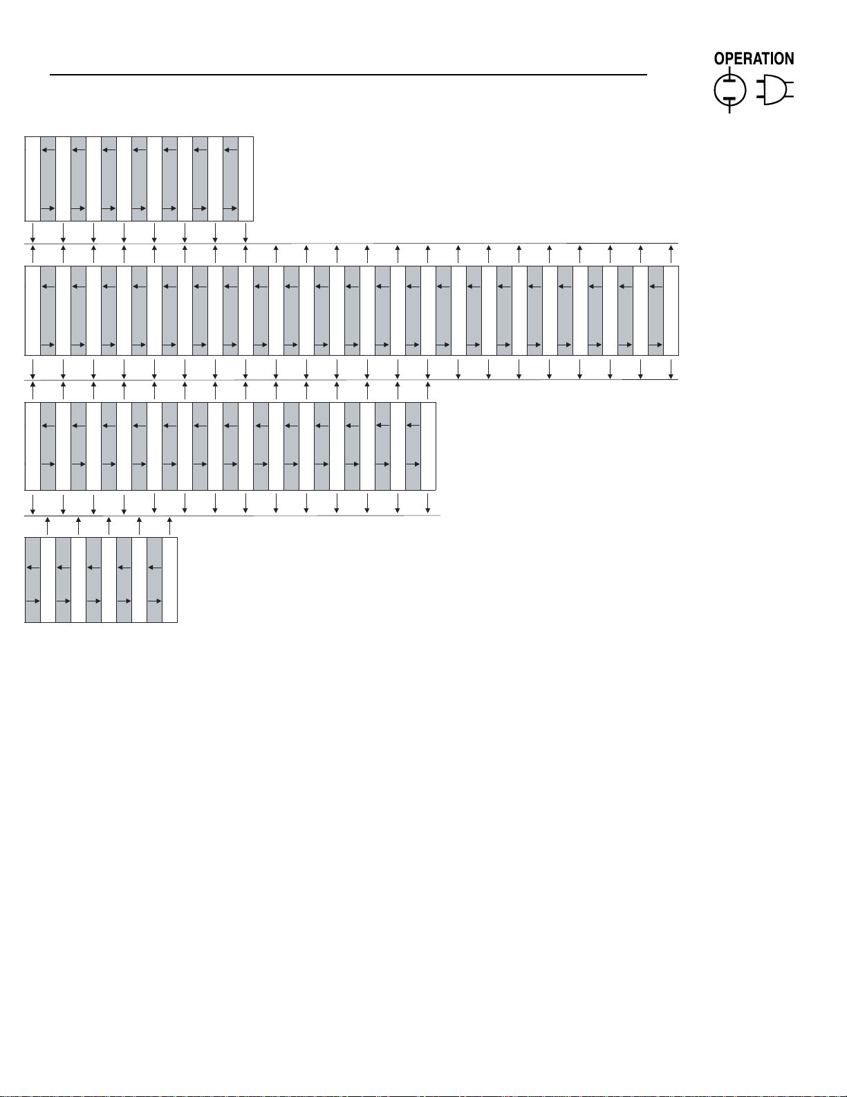
E PANEL DISPLAY MAP
Generac digital panel Generator switch off
Software version X.XX Generator switch off
will be on Attempting to start
X.X
or or or
or or or
or or or
or or or
or or or
Fuel Level High Enable Input Ch 7 Alarm Type Analog Ch 2 low Setpoint
Fuel Level Low Setpoint Input Channel 8 Message Analog Ch 2 High Enable
or or or
Under Freq Alarm Type Input Channel 7 Setting Analog 2 Low Alarm Msg
Fuel Level High Setpoint Input Ch 7 Alarm Enable Analog Ch 2 High Setpoint
or or or
or or or
XX.X Hz
Under Freq Setpoint Input Channel 7 Message Analog Ch 2 High Alarm Msg
Over Freq Alarm Type Input Ch 6 Alarm Type Analog Channel 2 Title
or or or
or or or
XX.X Hz X.X
Over Freq Setpoint Input Ch 6 Alarm enable Analog Ch 2 Value at 10V
Under Voltage Alarm Type Input Channel 6 Setting Analog Ch 2 value at 0V
or or or
or or or
XXX Volts
Under Voltage Setpoint Input Channel 6 Message Analog Ch 1 Low Type
or or or
or or or
XXX Volts
Over Voltage Setpoint Input Ch 5 Alarm Enable Analog Ch 1 Low Enable
Over Voltage Alarm Type Input Ch 5 Alarm Type Analog Ch 1 High Type
Parameter entry
Press Enter to Continue
Password Attempt number X
Or Enter Or Enter * Or Turn key to auto mode: Or
E-PANEL DISPLAY MAP
or
or
or
or or or or
X.X Enter
XXX Volts
Or
or
Thru Hours Run * Display test, stop command
Logged Alarm Number 50 XXXXX.X Hrs all pixels black, all 4 LEDs Turn key to manual mode:
ALARM STATUS ALARM LOG INSTRUMENTATION PARAMETER ENTRY SOFTWARE VERSION GENERATOR COMMAND
there are no messages Generator in auto mode
Analog Input 2 XXXXXX
X.X
Analog Input 1 Engine Parameter Menu Or System Alarm Menu Or Digital I/O Menu Or Analog Input menu
or
or
Direct Connection only
X RS485 Port
or
Fuel Level Low Fuel Shutdown Enable Input Ch 8 Alarm Type Analog Ch 2 Low Type
Battery Voltage RS 232 Port Low Fuel Shutdown Setpt Input Ch 8 Alarm enable Analog Ch 2 High Type
or
RS 232 Port
or
XXX p.s.I or
XX.X Volts Direct conection XX %
Oil Pressure Modem connection Fuel Level Low Enable Input Channel 8 Setting Analog Ch 2 Low Enable
or
or
RS 232 Port
to default settings
Restore all values
Modem connection & Setup
or
or
XXX deg F XX%
XXX deg. F X.X
Oil Temperature
Coolant Temperature
or
or
XXX
XXX.XX
Flywheel Teeth
Voltage Scaling Factor
or
or
XXXX Rpm XX% X.X
Engine Speed
Generator Frequency
Panel I.D.
XX.XHz
or
XXXXXX
or
XXXXXX
User Password
or
Preheat Option
or
or
XX.X Hz
XXX Volts
Load Accept Voltage
Load Accept Frequency
X
or
or
XXX RPM
Starter Disengage Speed
Number of Start Attempts
X Min
Generator Cool Down Time
STATUS
GENERATOR
Stopped ready to run No active messages * Logged Alarm Number 1 Generator Voltage
Or Or * this is true as long as Or
Page 21
Generac®Power Systems, Inc. 19
Section 2 — Operation
E Option Control Panels
X.X
or or or
or or or
XXXX Rpm
Underspeed Alarm Type Input Channel 5 Message Analog Ch 1 low Setpoint
Overspeed Shutdown Setpt Input Channel 5 Setting Analog Ch 1 High Enable
or or or
or or or
XX.X V
XXXX Rpm X.X
Underspeed Alarm Setpt Input Ch 4 Alarm Type Analog Ch 1 High Setpoint
Battery Volts Low Setpt Input Channel 4 Setting Analog Ch 1 High Alarm Msg
Battery Volts High Setpt Input Ch 4 Alarm Enable Analog 1 Low Alarm Msg
or or or
XX.X V
Coolant Temp low Setpt Input Channel 4 Message Analog Channel 1 Title
Analog Ch 1 Value at 10V
Input Ch 3 Alarm Type
or or or
or or or
XXX Deg F
XXX Deg F X.X
Coolant Temp Shutdn Setpt.
Analog Ch 1 value at 0V
Input Ch 3 Alarm Enable
or or
or or
XXX Deg F X.X
Coolant Temp High Setpt
Oil Temp Shutdown Enable Input Channel 3 Setting
or or
or or
XX Deg F
Oil Temp Warn Enable Input Ch 2 Alarm Type
Oil Temp. Shutdown Setpt Input Channel 3 Message
or or
or or
XX Psi
XX Deg F
Oil Temp. Warn Setpt Input Ch 2 Alarm Enable
Oil Press Shutdown Setpt Input Channel 2 Setting
or
or
Input Ch 1 Alarm Type
XX Psi
Oil Press Warn Setpt Input Channel 2 Message
or
or
or
or
Input Channel 1 Setting
Input Ch 1 Alarm Enable
Preheat Output Function
Input Channel 1 Message
or
Output 3 FunctionorOutput 2 Function
Output 1 Function
or
or
X Sec
Gen. Warm Up Time
or
XX Sec
XX Sec
Alarm Hold Off Time
Start Attempt Pause Time
or
or
XX Sec
Start Timer
XX Sec
Preheat Timer
Page 22
20 Generac®Power Systems, Inc.
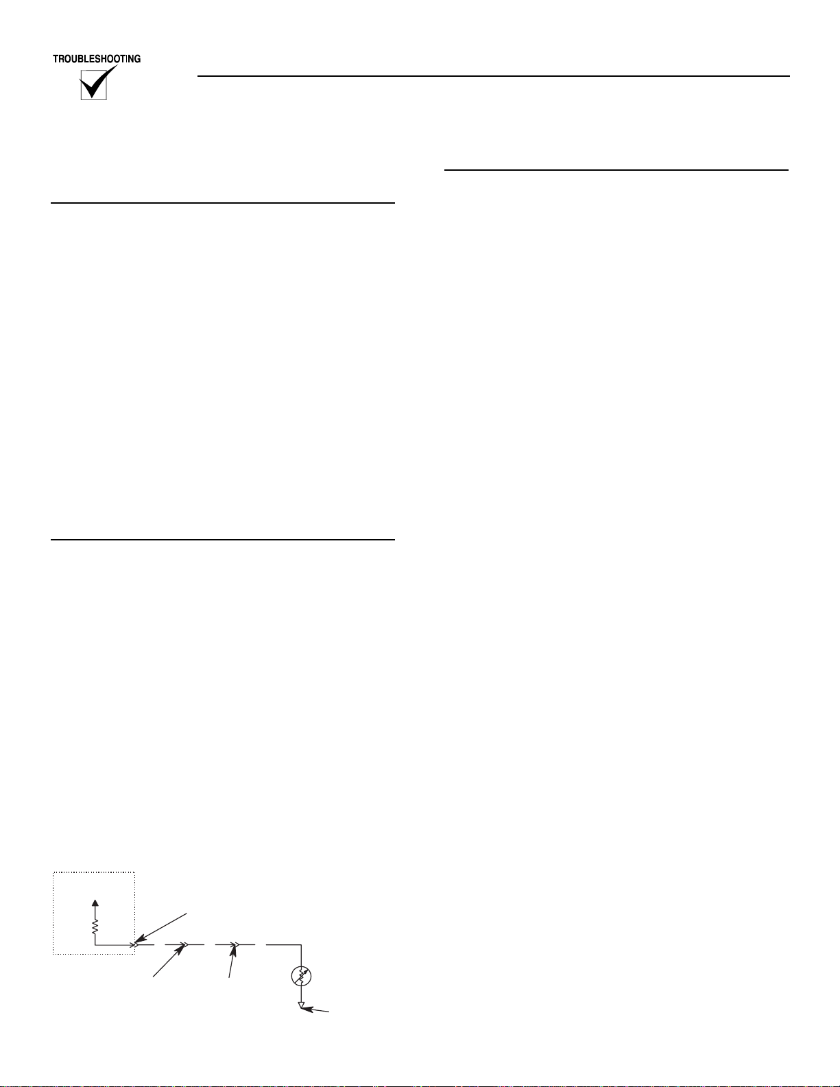
OIL PRESSURE SENSING (Refer to Figure 3.1)
OVERVIEW
An analog Oil Pressure Sender (OPS) is used for
monitoring the engine oil pressure. This sender
allows the E panel to measure and display the Engine
oil pressure.
Refer to the owners manual for the OPS part number
and mounting location.
Wire number 69 is used to connect the OPS to the E
Panel. The Ground for the OPS is made through the
engine block.
The OPS is a resistive device, whose resistance
changes based on engine oil pressure. The resistance
of the sender results in a voltage being developed
across the sender. As the oil pressure increases, the
resistance will decrease, causing the voltage to
decrease. This changing voltage is read by the E Panel
and converted into the engine Oil Pressure.
The E Panel will monitor and display oil pressure
anytime the DC input to the E Panel is present.
TROUBLESHOOTING
Prior to any troubleshooting, the oil pressure parameters programmed into the E Panel should be
checked and verified. The oil pressure input has two
different set points associated with it. They are:
Pre-Low Oil Pressure Warning: This is the warning
set point. The generator's alarm will sound, but the
generator will continue to run.
Critical Low Oil Pressure Alarm: This is the alarm
set point. The generator will shut down and sound
the alarm.
It is important to verify that these parameters are set
correctly for the specific unit. Check the E Panel settings against the Generator setup sheet. If the generator setup sheet is not available, contact Generac's
service department for the recommended settings.
Figure 3.1 — Oil Pressure Sender Connections
TESTING THE CONTROL PANEL
It is relatively easy to do a thorough test of the E
Panel's Oil Pressure input.
Place the Auto/Off/Manual switch to the Off position
during this testing.
Open circuit testing
This test checks the high end of the oil pressure input
of the E Panel.
1. Remove the 69 wire from the control panel terminal strip. This simulates a sender open circuit
condition.
2. Look for the following response from the E Panel:
The back light will flash, the Com Alarm LED will
flash, and the display will read as follows:
OIL PRESS SENSE FAULT
PRESS ENTER TO ACCEPT
3. Press enter to accept the alarm.
Short circuit testing
This test checks the low end of the oil pressure input
of the E Panel.
1. Reconnect the 69 wire to the control panel terminal strip.
Connect a jumper wire between the 69 and 0
positions on the control panel terminal strip. This
simulates a sender short circuit condition
2. Look for the following response from the E Panel
2.1 For units with software version V1.11 and
earlier: The back light will flash, the Com
Alarm LED will flash, and the display will
read as follows:
OIL PRESS SENSE FAULT
PRESS ENTER TO ACCEPT
Press enter to accept the alarm.
2.2 For units with software version V1.12 and
later:
Use the arrow keys to go to the Oil pressure
display screen.
The screen should display oil pressure as
125 p.s.i.
Control panel testing complete
1. Remove the jumper between the 69 and 0 locations on the control panel terminal strip.
2. If any E Panel alarms are present, press enter to
accept.
Test Results
1. Tests 1and 2 Pass:
Move on to the next test "Testing the Oil Pressure
Sender".
Section 3 — Troubleshooting and Diagnosis
E Option Control Panels
Oil Pressure Sender Connections
Refer to the unit's Wiring Diagram for specific connector locations
E Panel
+5V
69 Location on the
Control Panel
terminal strip
E Panel
CON 2-5
Set Screw
Connector
69 69
69 Location in the
Deutsch Connector
("Sealed Connector"
Control Panels only)
69
Oil Pressure
Sender
(OPS)
This Ground (0)
connection is
made through the
Engine Block
Page 23

Generac®Power Systems, Inc. 21
2. If either test 1 or 2 failed:
2.1 Repeat the open and short circuit testing
directly at the back of the E Panel as follows:
Open: The 69 wire should be removed from
CON2-5
Short: With the 69 wire still removed, insert
a jumper wire into CON2-5. Connect
the other end of the jumper to ground
(0).
After testing, remove the jumper wire from
CON2-5 and insert the 69 wire back into
CON2-5
2.2 Test results:
2.2.1 If these tests fail again directly at the
back of the E Panel, then the E Panel
has failed and should be replaced.
2.2.2 If these tests pass at the back of the E
Panel, but failed at the terminal strip,
then there is a wiring error between the
E Panel and the terminal strip. Check
this wiring carefully.
TESTING THE OIL PRESSURE SENDER
The resistance of the OPS can be checked in a power
down state as follows:
1. Remove the control panel fuse to power down the
E panel.
2. Unplug CON2 from the E Panel.
3. Measure the resistance of the oil pressure sender.
This measurement should be made between the
sender terminal and the sender body.
The sender resistance should measure between 225
and 260 Ohms at 0 PSI.
NOTE:
If the engine has just been stopped, allow sufficient time for the oil pressure to drop to zero
before making this measurement.
If the resistance measurement is not in this range, the
sender has failed. Replace the sender.
If the resistance measurement is in this range, move
on to the next test.
TESTING THE OIL PRESSURE SENDER
CONNECTIONS
Visual Inspection
Carefully check the wiring between the oil pressure
sender and the E Panel.
1. Check the 69 wire connection to the OPS.
1.1 Check for a proper crimp on the lug.
1.2 Check to see if the sender nut is tightened
securely. Be careful not to over tighten the
nut. If the nut is over tightened, the stud will
break free and cause incorrect sender readings. This nut should be tightened to 14 to 18
inch pounds.
1.3 Check for any environmental corrosion on
the lug or the sender terminal. Generac recommends the following actions if corrosion is
found:
1.3.1 Replace the lug.
1.3.2 Replace the sender if possible. If not
possible, thoroughly remove all of the
corrosion from the sender terminal.
1.3.3 Protect the lug and sender terminal
with an approved automotive dielectric
grease.
2. Check the 69 wire in the Deutsch connector (only
used on the "water tight connector" panels.)
2.1 Refer to appendix A for information on the
Deutsch connectors used.
2.2 Refer to the unit's wire diagram for the 69
location in the Deutsch plug.
3. Check the 69 wire on the control panel terminal
strip.
3.1 Check for a proper crimp on both lugs.
3.2 Check to see if both screws are tightened
securely. These screws should be tightened to
12 inch pounds.
4. Check the 69 wire going into CON2 on the back of
the E Panel.
4.1 Check to see if the wire is stripped properly
inside the green plug. The wire conductor
should be trapped inside the metal wire
clamp. The wire insulation should not be
trapped inside the metal wire clamp.
4.2 Check to see if the set screw is tightened
securely, but do not over tighten. This screw
should be set to 2 to 4 inch pounds.
5. Check for any wire damage along the entire run
between the E Panel and the sender.
5.1 Check for any areas along the wire with missing insulation. This could allow the 69 line to
momentarily come into contact with ground
causing a false shut down.
5.2 Check to see if the wire is pinched anywhere
along the run. A wire that is pinched between
the sheet metal can cause the 69 wire to
momentarily come into contact with ground
resulting in a shut down fault. A pinched wire
may also cause the wire to break inside the
insulation. This could cause the 69 line to
monetarily "open" while running. This will
also result in a shut down fault.
Section 3 — Troubleshooting and Diagnosis
E Option Control Panels
Page 24

22 Generac®Power Systems, Inc.
Check the OPS mounting
The ground return (0) connection for the OPS is
made by the physical connection of the sender to the
engine block. This connection may be made directly,
or through a series of adapters or fittings.
Check for the following at each junction point:
1. Check for a tight mechanical connection.
2. Check for a good electrical connection.
Resistance measurement
The resistance of the OPS was measured in "Testing
the Oil Pressure Sender."
In that test, the resistance was measured directly
across the OPS. This test will now measure that same
resistance inside the control panel. This will provide
an additional test of the wiring and connections used
to connect the sender to the control panel.
1. Remove the control panel fuse to power down the
E Panel.
2. Unplug CON2 from the E Panel.
3. Measure the resistance between the 69 and 0 locations on the control panel terminal strip.
4. Compare this measurement to the measurement
taken directly across the OPS.
4.1 If this measurement is more than 2-3 Ohms
greater than the one taken directly across the
OPS, there is a problem with the sender connections. You can determine if the problem is
the 69 connection or the 0 connection as follows:
4.1.1 Measure the resistance between the
OPS stud and the 69 wire inside the
control panel. If this measurement is
greater than 2-3 Ohms, replace the
entire wire running between the control
panel and the OPS stud.
Repeat step D, measuring the resistance between the 69 and 0 locations on
the control panel terminal strip and
comparing it to the earlier reading.
4.1.2 Measure the resistance between the
body of the sender and the 0 location
on the control panel terminal strip. If
this measurement is greater than 2-3
Ohms, go back and carefully check the
following:
4.1.2.1 OPS mounting, including all
fittings and adapters.
4.1.2.2 Remove the OPS and check the
conditions of the threads.
Check for an excessive amount
of pipe sealant on the threads.
Ensure there is no pipe sealant
on the end of the sender covering the oil inlet hole. Repeat
step D, measuring the resistance between the 69 and 0
locations on the control panel
terminal strip and comparing
it to the earlier reading.
4.2 If this measurement is less than 2-3 Ohms
greater than the one taken directly across the
OPS, and a thorough visual inspection was
performed, the wiring is OK.
LOW COOLANT LEVEL (Refer to Figure 3.2)
OVERVIEW
A Low Coolant Level (LCL) sensor is placed in the
generator's coolant system. This sensor allows the E
Panel to detect a Low Coolant Level condition.
Wire number 85 is used to connect the LCL to the E
Panel. The Ground for the LCL is made through the
radiator frame or engine block (depending on where
the LCL is located). The LCL is a resistive device
whose resistance changes based on the temperature
of the LCL.
The resistance of the LCL results in a voltage being
developed across the LCL. This voltage changes as
the resistance changes. This changing voltage is read
by the E Panel.
The LCL is supplied with current from the E Panel.
This current will cause the LCL to generate heat. If
the LCL is in coolant, the coolant will keep the LCL
from heating up. If the LCL is in air, it will heat up
telling the E panel there is a low coolant condition.
In most systems, a back up High Water Temperature
(HWT) switch is wired in parallel with the LCL. This
switch is a normally open switch whose contacts will
close at a predetermined temperature setting. If this
HWT switch closes, it will result in the E Panel shutting down with a "Low Coolant Level" display.
Refer to owners manual for the LCL and HWT part
numbers and mounting locations.
The E Panel checks for low coolant level as follows:
Software version V1.03 and earlier: Will check for
a low coolant level anytime the DC input to the E
Panel is present.
Software version V1.04 and later: Will only check
for a low coolant level once the engine has started and
the hold off timer has expired.
There are no user-definable parameters for the Low
Coolant Level.
Section 3 — Troubleshooting and Diagnosis
E Option Control Panels
Page 25

Generac®Power Systems, Inc. 23
TROUBLESHOOTING
Figure 3.2 — Water Level Sensor Connections
TESTING THE CONTROL PANEL
It is relatively easy to do a thorough test of the E
Panel's Low Coolant Level input.
In most cases it is necessary to run the engine while
doing this testing.
Once the engine has started, there will be high
voltage inside the generator's control panel
and at CON4 of the E Panel.
Open circuit testing
This test checks the high end of the low coolant level
input.
1. With the generator stopped, remove the 85 wire
from the control panel terminal strip. This simulates a sender open circuit condition.
2. Start the Generator.
2.1 The generator should not shut down on Low
Coolant Level with the 85 wire disconnected.
If the generator does shutdown on low
coolant level, there is a fault with the E Panel.
2.2 With the 85 wire still disconnected, use a DC
volt meter to measure the voltage between the
85 wire (the end still connected to the E
Panel) and ground. This voltage should be 10
volts DC or greater.
If this voltage is below 10 volts DC, there is a
fault with the E Panel. Replace the E Panel.
2.3 Stop the generator.
Short circuit testing
This test checks the low end of the low coolant level
input.
1. Reconnect the 85 wire to the control panel terminal strip. Connect a jumper wire between the 85
and 0 locations on the control panel terminal
strip. This simulates the HWT switch closing to
ground.
2. The E panel should respond as follows:
2.1 E Panels with V1.03 and earlier software:
The E Panel will sound the alarm and display
a low coolant level fault.
2.2 E Panels with V1.04 and later software: Start
the generator and observe the following:
2.2.1 The E Panel should start normally.
2.2.2 Once the engine has started, the hold
off timer will start.
2.2.3 Once the hold off timer expires, the E
Panel will shut the engine down and
display a low coolant alarm.
Control panel testing complete
1. Shut down the generator engine.
2. Remove the jumper between the 85 and 0 locations.
Test Results
1. Tests 1 and 2 Pass:
Move on to the next test "Checking the wiring
between the E Panel and the LCL/HWT".
2. If either test 1 or 2 failed:
2.1 Repeat the open and short circuit testing
directly at the back of the E Panel as follows:
Open: The 85 wire should be removed from
CON2-7.
Short: With the 85 wire still removed, insert
a jumper wire into CON2-7. Connect
the other end of the jumper to ground
(0).
After testing, remove the jumper wire from
CON2-7 and insert the 85 wire back into
CON2-7.
2.2 Test results:
2.2.1 If these tests fail again directly at the
back of the E Panel, then the E Panel
has failed and needs to be replaced.
2.2.2 If these tests pass at the back of the E
Panel, but failed at the terminal strip,
then there is a wiring error between the
E Panel and the terminal strip. Check
this wiring carefully.
Section 3 — Troubleshooting and Diagnosis
E Option Control Panels
Water Level Sensor Connections
Refer to the unit's Wiring Diagram for specific connector locations
E Panel
CON 2-7
Set Screw
E Panel
Supply
Connector
85 85
85 Location on the
Control Panel
terminal strip
85 Location in the
Deutsch Connector
("Sealed Connector"
Control Panels only)
85
Low Coolant
Level Sensor
(LCL)
connections are made
Frame or Engine Block
85
These Ground (0)
through the Radiator
High Water
Temperature Switch
(Normally Open)
HWT
Page 26

24 Generac®Power Systems, Inc.
CHECK THE WIRING BETWEEN THE E PANEL
AND THE LCL/HWT
The Low coolant level input is active low. This means
that a short to ground on the 85 line will cause the E
Panel to shut down for Low coolant level.
Very carefully check the 85 wire from the back of the
E Panel out to the LCL and HWT. Check for the following:
1. Check for any areas along the wire with missing
insulation. This could allow the 85 line to momentarily come into contact with ground causing a
shut down.
2. Check to see if the wire is pinched anywhere along
the run. A wire that is pinched against sheet metal
can cause the 85 wire to momentarily come into
contact with ground resulting in a shut down.
A pinched wire may also cause the wire to break
inside the insulation. This could cause the 85 line
to momentarily "open" while running. This "open"
condition would not result in a false shutdown,
but it could prevent the E Panel from shutting
down the generator in the event of a true failure.
3. Check the 85 wire connection to the LCL
3.1. Check for a proper crimp on the lug.
3.2 Check for any environmental corrosion on
the lug or the switch terminal. Generac recommends the following actions if corrosion is
found:
3.2.1 Replace the lug.
3.2.2 Replace the sender if possible. If not
possible, thoroughly remove all of the
corrosion from the sender terminal.
3.3.3 Protect the lug and sender terminal
with an approved automotive dielectric
grease.
4. Check the 85 wire connection to the HWT switch.
4.1 Check for a proper crimp on the lug.
4.2 Check for any environmental corrosion on
the lug or the switch terminal. We recommend
the following actions if corrosion is found:
4.2.1 Replace the lug.
4.2.2 Replace the switch if possible. If not
possible, thoroughly remove all of the
corrosion from the sender terminal.
4.2.3 Protect the lug and switch terminal
with an approved automotive dielectric
grease.
5. Check the 85 wire in the Deutsch connector (only
used on "water tight connector" panels.)
5.1 Refer appendix A for information on the
Deutsch connectors used.
5.2 Refer to the unit's wiring diagram for the specific wire location.
6. Check the 85 wire on the control panel terminal
strip.
6.1 Check for a proper crimp on both lugs.
6.2 Check to see that both screws are tightened
securely. These screws should be tightened to
12 inch pounds.
7. Check the 85 wire going into CON2 on the back of
the E Panel.
7.1 Check to see the wire is stripped correctly.
The wire conductor should be trapped inside
the metal wire clamp. The wire insulation
should not be inside the metal wire clamp.
7.2 Check to see if the set screw is tightened
securely. This screw should be set to 2 to 4
inch pounds.
8. Check the LCL and the HWT mounting. The
ground return (0) connection for these devices is
made by the physical connection of the device
body to the engine block/radiator frame. These
connections can be made directly or through a
series of adapters or fittings. Check for a good
mechanical and electrical connection at each junction point.
TESTING THE LCL/HWT
1. Check the devices while the generator is not running.
1.1 Test the resistance of the LCL.
1.1.1 Remove the front panel fuse to power
down the E Panel.
1.1.2 Unplug CON2 from the E Panel.
1.1.3 Disconnect the 85 wire from the LCL.
1.1.4 Measure the resistance of the LCL. This
measurement should be taken from the
sender terminal to the sender body.
The sender should measure between
40 and 65 ohms. This resistance will
vary with temperature. It will be closer
to 40 ohms at 30F, and closer to 65
ohms at 120F.
If the resistance measurement is not in
this range, the sender has failed and
needs to be replaced.
1.1.5 Reconnect the 85 wire to the LCL.
1.2 Test the HWT switch.
1.2.1 Disconnect the 85 wire from the HWT
switch.
1.2.2 Measure the resistance of the HWT
switch. This resistance should be taken
from the switch terminal to the switch
body.
1.2.3 This resistance should measure "infinity" or "open circuit". If not, the switch
has failed and needs to be replaced.
1.2.4 Reconnect the 85 wire to the HWT
switch. Plug CON2 back into the E
Panel. Replace the front panel fuse.
Section 3 — Troubleshooting and Diagnosis
E Option Control Panels
Page 27

Generac®Power Systems, Inc. 25
2. Check the devices while the generator is running.
If the E Panel is still shutting down on low coolant
level, and both devices check good in the power
down state, the devices can be checked while the
engine is running. The following tests will isolate
the two different senders and determine which
sender is causing the shutdown.
NOTE:
It is very important that the wiring between the E
Panel and the LCL/HWT was carefully checked as
described above. Incorrect wiring or damage to
any of the wiring can result in false test results.
2.1 Test the HWT switch.
2.1.1 Disconnect the 85 wire connected to
the LCL. Position the wire such that the
lug will not come into contact with any
metal surface.
2.2.2 Start and run the generator. If the generator shuts down with a low coolant
level alarm, the HWT switch is the
cause. Replace the HWT switch.
If the generator does not shut down on
alarm, stop the generator and proceed
to the next test.
2.2 Test the LCL sender.
2.2.1 Reconnect the 85 wire to the LCL.
2.2.2 Disconnect the 85 wire connected to
the HWT switch. Position the wire such
that the lug will not come into contact
with any metal surface.
2.2.3 Start and run the generator. If the generator shuts down with a low coolant
level alarm, the LCL is the cause.
Replace the LCL.
If the generator does not shut down on
alarm, stop the generator manually.
2.2.4 Reconnect the 85 wire to the HWT.
COOLANT TEMPERATURE SENSING
(Refer to Figure 3.3)
OVERVIEW
An analog Water Temperature Sender (WTS) is located in the engine's cooling system. This sender is connected to the E Panel and allows the E Panel to monitor and display the temperature of the Coolant system. Wire number 68 is used to connect the WTS to
the E Panel. The ground for the WTS is made through
the radiator frame or engine block (depending on
where the WTS is located).
Refer to the owners manual for the WTS part number
and mounting location.
The WTS is a resistive device whose resistance
changes based on coolant temperature. The resistance of the sender results in a voltage being developed across the sender. As the Coolant temperature
increases, the resistance will decrease, causing the
voltage to decrease. This changing voltage is read by
the E Panel and converted into coolant temperature.
The E Panel will monitor and display the coolant
temperature anytime the DC input to the E Panel is
present.
TROUBLESHOOTING
Prior to any troubleshooting, the Coolant
Temperature parameters programmed into the E
Panel should be checked and verified. The coolant
temperature has three different set points associated
with it. They are:
• Low Coolant Temp Warning: This is a warning set
point. The generator's alarm will sound, but the
unit will continue to run.
• Pre-High Coolant Temp Warning: This is a warn-
ing set point. The generator's alarm will sound, but
the unit will continue to run.
• High Coolant Temp Alarm: This is the alarm set
point. The generator will shut down and sound the
alarm.
It is important to verify that these parameters are set
correctly for the specific unit. Check the E Panel settings against the generator setup sheet. If the generator setup sheet is not available, contact Generac's
service department for the recommended settings.
Figure 3.3 — Water Temperature Sender
Connections
TESTING THE CONTROL PANEL
It is relatively easy to do a thorough test of the E
Panel's Coolant Temperature input.
Place the Auto/Off/Manual switch to the Off position
during this testing.
Section 3 — Troubleshooting and Diagnosis
E Option Control Panels
Water Temperature Sender Connections
Refer to the unit's Wiring Diagram for specific connector locations
E Panel
+5V
68 Location on the
Control Panel
E Panel
CON 2-6
Set Screw
Connector
68 68
68 Location in the
terminal strip
Deutsch Connector
("Sealed Connector"
Control Panels only)
68
The Sender may
be located in the
Radiator or
Engine Block
Water
Temperature
Sender
(WTS)
made through the
Radiator Frame or
This Ground (0)
connection is
Engine Block
Page 28

26 Generac®Power Systems, Inc.
Open circuit testing
This test checks the high end of the coolant temperature input of the E Panel.
1. Remove the 68 wire from the control panel terminal strip. This simulates a sender open circuit
condition.
2. Look for the following response from the E Panel.
The E Panel should respond in either one of the
following ways:
2.1 The Coolant temperature display will read
less than 20 F.
OR
2.2 The back light will flash, the com alarm LED
will flash, and the display will read as follows:
OIL TEMP SENSE FAULT
PRESS ENTER TO ACCEPT
Short circuit testing
This test checks the low end of the coolant temperature input of the E Panel.
1. If any E Panel alarms are present, press enter to
accept.
2. Reconnect the 68 wire to the control panel terminal strip.
3. Connect a jumper wire between the 68 and 0 positions on the control panel terminal strip. This
simulates a sender short circuit condition.
4. Look for the following response from the E Panel.
The back light will flash, the Com Alarm LED will
flash, and the display will read as follows:
COOLANT TEMP SENSE FAULT
PRESS ENTER TO ACCEPT
Press enter to accept the alarm.
Control panel testing complete
1. Remove the jumper between the 68 and 0 locations.
2. If any E Panel alarms are present, press enter to
accept.
Test Results
1. Tests 1 and 2 pass:
Move on to the next test "Testing the coolant tem-
perature sender connections".
2. If either Test 1 or 2 failed:
2.1 Repeat the open and short circuit testing at
the back of the E Panel as follows:
Open: The 68 wire should be removed from
CON2-6.
Short: With the 68 wire still removed, insert
a jumper wire into CON2-6. Connect
the other end of the jumper to ground
(0).
After testing, remove the jumper wire from
CON2-6 and insert the 68 wire back into CON2-
6.
2.2 Test results:
2.2.1 If these tests fail again directly at the
back of the E Panel, then the E Panel
has failed and should be replaced.
2.2.2 If these test pass at the back of the E
Panel, but failed at the terminal strip,
then there is a wiring error between the
E Panel and the terminal strip. Check
this wiring carefully.
TESTING THE COOLANT TEMPERATURE
SENDER CONNECTIONS
Visual Inspection
Carefully check the wiring between the coolant temperature sender and the E Panel.
1. Check the 68 wire connection to the WTS.
1.1 Check for a proper crimp on the lug.
1.2 Check to see if the sender nut it tightened
securely. Be careful not to over tighten the
nut. If the nut is over tightened the stud will
break free and cause incorrect sender readings. This nut should be tightened to 6 to 7
inch pounds.
1.3 Check for any environmental corrosion on
the lug or sender terminal. Generac recommends the following actions if corrosion is
found:
1.3.1 Replace the lug.
1.3.2 Replace the sender if possible. If not
possible, thoroughly remove all of the
corrosion from the sender terminal.
1.3.3 Protect the lug and sender terminal
with an approved automotive dielectric
grease.
2. Check the 68 wire in the Deutsch connector (only
used on the "water tight connector" panels.)
2.1 Refer to appendix A for information on the
Deutsch connectors used.
2.2 Refer to the units wiring diagram for the 68
location in the Deutsch plug.
3. Check the 68 wire on the control panel terminal
strip.
3.1 Check for a proper crimp on both lugs.
3.2 Check to see if both screws are tightened
securely. These screws should be tightened to
12 inch pounds.
4. Check the 68 wire going into CON2 on the back of
the E Panel.
4.1 Check to see if the wire is stripped properly
inside the green plug. The wire conductor
should be trapped inside the metal wire
clamp. The wire insulation should not be
trapped inside the metal wire clamp.
Section 3 — Troubleshooting and Diagnosis
E Option Control Panels
Page 29

Generac®Power Systems, Inc. 27
4.2 Check to see if the set screw is tightened
securely, but do not over tighten. This screw
should be set to 2 to 4 inch pounds.
5. Check for any wire damage along the entire run
between the E Panel and the sender.
5.1 Check for any areas along the wire with missing insulation. This could allow the 68 line to
momentarily come into contact with ground
causing a false shut down.
5.2 Check to see if the wire is pinched anywhere
along the run. A wire that is pinched between
the sheet metal can cause the 68 wire to
momentarily come into contact with ground
causing a false shut down. A pinched wire
may also cause the wire to break inside the
insulation, this could cause the 68 line to
momentarily "open" while running. This will
also result in a false shut down.
Check the WTS mounting
The ground return (0) connection for the WTS is
made by the physical connection of the sender to the
engine block. This connection may be made directly,
or through a series of adapters or fittings.
Check for the following at each junction point:
1. Check for a tight mechanical connection.
2. Check for a good electrical connection.
Resistance measurements
Power down the E Panel by removing the front panel
fuse.
Remove CON2 from the back of the E Panel.
1. Measure the resistance between the WTS stud and
the 68 wire inside the control panel. If this measurement is greater than 2-3 Ohms, replace the
entire wire running between the control panel and
the WTS stud.
2. Measure the resistance between the body of the
sender and the 0 location on the control panel terminal strip. If this measurement is greater than 2
-3 Ohms, go back and carefully check the WTS
mounting and the star ground connections on the
engine block.
OIL TEMPERATURE SENSING
(Refer to Figure 3.4)
OVERVIEW
Oil Temperature sensing is an OPTION offered with
the E Panel. When ordered, an analog Oil
Temperature Sender (OTS) is mounted in the oil pan.
This sender is connected to the E Panel and allows
the E Panel to monitor and display the temperature
of the engine oil. Wire number 523 is used to connect
the OTS to the E Panel. The ground for the OTS is
made through the oil pan/engine block.
The OTS is a resistive device, whose resistance
changes based on oil temperature. The resistance of
the sender results in a voltage being developed across
the sender. As the oil temperature increases, the
resistance will decrease, causing the voltage to
decrease. This changing voltage is read by the E Panel
and converted to oil temperature.
TROUBLESHOOTING
Prior to any troubleshooting, verify the following:
1. Verify the oil temperature option has been ordered
and installed on the generator.
2. Check and verify the Oil Temperature parameters
programmed into the E Panel. The oil temperature
has two different set points associated with it.
Pre-High Oil Temp Warning: This is a warning
set point. The generator's alarm will sound but the
generator will continue to run. This parameter
should be Disabled if no sender was fitted.
High Oil Temp Alarm: This is an alarm set point.
The generator will shut down and sound the
alarm. This parameter should be Disabled if no
sender was fitted.
It is important to verify that these parameters are set
correctly for the specific unit. Check the E Panel settings against the Generator setup sheet. If the generator setup sheet is not available, contact Generac's
service department for the recommended settings.
Figure 3.4 — Optional Oil Temperature Sender
Connections
TESTING THE CONTROL PANEL
It is relatively easy to do a thorough test of the E
Panel's Oil Temperature input.
Place the Auto/Off/Manual switch to the Off position
during this testing.
Section 3 — Troubleshooting and Diagnosis
E Option Control Panels
Oil Temperature Sender Connections
Optional
Refer to the unit's Wiring Diagram for specific connector locations
E Panel
+5V
523 Location on the
E Panel
CON 2-4 Set
Screw
Connector
523 523
Control Panel
terminal strip
523 Location in the
Deutsch Connector
("Sealed Connector"
Control Panels only)
523
Oil Temperature
Sender
(OTS)
This Ground (0)
connection is made
through the Oil
Pan/Engine Block
Page 30

28 Generac®Power Systems, Inc.
Open circuit testing
This test checks the high end of the oil Temperature
input of the E Panel.
1. Remove the 523 wire from the control panel terminal strip. This simulates a sender open circuit
condition.
2. The E Panel should respond in either one of the
following ways:
2.1 The Coolant temperature display will read
less than 20 F.
OR
2.2 The back light will flash, the com alarm LED
will flash, and the display will read as follows:
OIL TEMP SENSE FAULT
PRESS ENTER TO ACCEPT
Short circuit testing
This test checks the low end of the oil temperature
input of the E Panel.
1. Reconnect the 523 wire to the control panel terminal strip.
2. Connect a jumper wire between the 523 and 0
locations on the control panel terminal strip. This
simulates a sender short circuit condition.
3. Look for the following response from the E Panel.
The back light will flash, the Com Alarm LED will
flash, and the display will read as follows:
OIL TEMP SENSE FAULT
PRESS ENTER TO ACCEPT
Press enter to accept the alarm.
Control Panel testing complete
1. Remove the jumper between the 523 and the 0
locations on the control panel terminal strip.
2. If any E Panel alarms are present, press enter to
accept.
Test results
1. Tests 1 and 2 pass:
Move on to the next test "testing the oil tempera-
ture sender connections".
2. If either test 1 or test 2 failed:
2.1 Repeat the open and short circuit testing
directly at the back of the E Panel as follows:
Open: The 523 wire should be removed from
CON2-4.
Short: With the 523 wire still removed, insert
a jumper wire into CON2-4. Connect the
other end of the jumper to ground (0).
After testing, remove the jumper wire from
CON2-4 and insert the 523 wire back into
CON2-4.
2.2 Test results:
2.2.1 If these tests fail again directly at the
back of the E Panel, then the E Panel
has failed and should be replaced.
2.2.2 If these tests pass at the back of the E
Panel, but failed at the terminal strip,
then there is a wiring error between the
E Panel and the terminal strip. Check
this wiring carefully.
TESTING THE OIL TEMPERATURE SENDER
CONNECTIONS
Visual Inspection
Carefully check the wiring between the oil temperature sender and the E Panel.
1. Check the 523 wire connection to the OTS.
1.1 Check for a proper crimp on the lug.
1.2 Check to see if the sender nut is tightened
securely. Be careful not to over tighten the
nut. If the nut is over tightened the stud will
break free and cause incorrect sender readings. This nut should be tightened to 6 to 7
inch pounds.
1.3 Check for any environmental corrosion on
the lug or sender terminal. Generac recommends the following actions if corrosion is
found:
1.3.1 Replace the lug.
1.3.2 Replace the sender if possible. If not
possible, thoroughly remove all of the
corrosion from the sender terminal.
1.3.3 Protect the lug and sender terminal
with an approved automotive dielectric
grease.
2. Check the 523 wire in the Deutsch connector (only
used on the "water tight connector" panels.)
2.1 Refer to appendix A for information on the
Deutsch connectors used.
2.2 Refer to the unit's wiring diagram for the 523
location in the Deutsch plug.
3. Check the 523 wire on the control panel terminal
strip.
3.1 Check for a proper crimp on both lugs.
3.2 Check to see if both screws are tightened
securely. These screws should be tightened to
12 inch pounds.
4. Check the 523 wire going into CON2 on the back
of the E Panel.
4.1 Check to see if the wire is stripped properly
inside the green plug. The wire conductor
should be trapped inside the metal wire
clamp. The wire insulation should not be
trapped inside the metal wire clamp.
Section 3 — Troubleshooting and Diagnosis
E Option Control Panels
Page 31

Generac®Power Systems, Inc. 29
4.2 Check to see if the set screw is tightened
securely, but do not over tighten. This screw
should be set to 2 to 4 inch pounds.
5. Check for any wire damage along the entire run
between the E Panel and the sender.
5.1 Check for any areas along the wire with missing insulation. This could allow the 523 line
to momentarily come into contact with
ground causing a false shut down.
5.2 Check to see if the wire is pinched anywhere
along the run. A wire that is pinched between
the sheet metal can cause the 523 wire to
momentarily come into ground causing a false
shut down. A pinched wire may also cause the
wire to break inside the insulation, this could
cause the 523 line to momentarily "open"
while running. This will also result in a false
shut down.
Check the OTS mounting
The ground return (0) connection for the OTS is
made by the physical connection of the sender to the
engine block. This connection may be made directly,
or through a series of adapters or fittings.
Check for the following at each junction point:
1. Check for a tight mechanical connection.
2. Check for a good electrical connection.
Resistance measurements
Power down the E Panel by removing the front panel
fuse.
Remove CON2 from the back of the E Panel.
1. Measure the resistance between the OTS stud and
the 523 wire inside the control panel. If this measurement is greater than 2-3 Ohms, replace the
entire wire running between the control panel and
the OTS stud.
2. Measure the resistance between the body of the
sender and the 0 location on the control panel terminal strip. If this measurement is greater than 2
-3 Ohms, go back and carefully check the OTS
mounting and the star ground connections on the
engine block.
AC VOLTAGE DISPLAY
The E Panel monitors the generator's AC output voltage. This voltage can be viewed locally on the E
Panel's display, or remotely using Genlink.
There are two user programmable set points for the
Generator output voltage: over voltage and under
voltage. Both parameters are active after the hold off
timer has expired. They can be programmed to be a
status message, non-latched alarm, latched alarm, or
shut down alarm.
The voltage displayed on the E Panel, and the
over/under voltage set points are all based on the generators full line to line output voltage. However, in
most cases full line to line voltage is not connected to
the E Panel. (Please refer to the unit's wiring diagram
and schematic for complete wiring details.)
The E Panel has a programmable voltage scaling factor that is used to scale the sensing voltage applied to
CON4-4 and CON4-6. This allows the E Panel to display full line to line voltage.
The scaling factor should be checked if the E Panel is
not displaying the line to line voltage correctly.
Check the scaling factor against the generators set up
sheet. If the set up sheet is not available, contact
Generac's service department for the recommended
setting.
The voltage scaling factor can also be used to "calibrate" the voltage display.
Example:
A 480 volt unit has 240 volts sensing voltage applied
to E Panel CON4-4 and CON4-6.
The E Panels scaling factor should be set to 2.0 to
provide a proper line to line display voltage.
If, however, the E Panel displays 490 volts with a scaling factor of 2.0, the scale factor may be adjusted
slightly to "calibrate" the voltage display. In this case,
the displayed voltage is roughly 2% high, so the scaling factor should be reduced by 2% to 1.96. Change
the scaling factor and recheck the voltage display. If
necessary, readjust the scaling factor until the voltage
display is properly "calibrated".
Please note the following:
1. Software versions V1.07 and earlier had a one
decimal point scale factor.
Software versions V1.08 and later have a two decimal point scale factor.
2. The E Panel displayed voltage is not used in any
way to regulate the generators output voltage. The
voltage regulator is responsible for regulating generator voltage.
RPM SENSOR AND ENGINE SPEED
ALARMS
(Refer to Figures 3.5, 3.6 & 3.7)
OVERVIEW
The E Panel uses an RPM sensor to monitor engine
speed. The RPM sensor is mounted in the blower
housing and positioned so the tip of the sensor is
directly above the engine flywheel teeth. As the flywheel rotates, the sensor will send an electrical pulse
to the E Panel each time a tooth passes the sensor.
The E Panel will count these pulses and convert them
into engine speed.
Section 3 — Troubleshooting and Diagnosis
E Option Control Panels
Page 32

30 Generac®Power Systems, Inc.
Figure 3.5 — RPM Sensor
If the magnetic pickup is removed for any reason, it
must be installed properly.
INSTALLATION
1. Rotate the ring gear until a gear tooth face is
directly in the center of the tapped hole on the
blower housing.
NOTE:
Do NOT use the alternator fan to rotate the engine.
2. Gently turn the magnetic pick up clockwise into
the tapped hole until it bottoms on the gear tooth.
3. Use a marker to mark a line on the magnetic pick
up threads and blower housing.
4. Using the lines marked in Step 3 as a guide, turn
the magnetic pick up 1/2 to 3/4 of a turn counterclockwise.
5. Tighten the jam nut securely.
RELATED ALARMS
RPM Sensor Loss
RPM sensor loss is a shut down alarm. There are two
conditions that will result in RPM sensor loss.
1. No RPM signal at crank. The E Panel will monitor
the RPM sensor during the crank cycle. If no signal is detected within a few seconds of cranking,
the E Panel will display RPM Sensor Failure and
shut down the engine.
2. RPM sensor loss while running. The E Panel continues to monitor the RPM sensor while running.
If the signal is lost while running, the E Panel will
display RPM sensor failure and shut down the
engine.
Engine Under Speed
Engine under speed is a hold off alarm with a programmable set point. The alarm type is programmable as shutdown, latched, non-latched or status.
Engine Over Speed
Engine over speed is an immediate alarm with a programmable set point. Engine over speed is a shut
down alarm.
TROUBLESHOOTING
1. Verify that all the following parameters have been
correctly programmed into the E Panel.
1.1 Number of flywheel teeth. The number of flywheel teeth is used by the E Panel to convert
the electrical pulses from the RPM sensor,
into engine speed. If this parameter is not
programmed correctly, the E Panel will not be
able to monitor engine speed correctly. Verify
the number of flywheel teeth against the generator setup sheet. If the generator setup
sheet is not available, contact Generac's service department for the REQUIRED setting.
1.2 Over speed and under speed settings. Verify
these settings against the generator setup
sheet. If the generator setup sheet is not available, contact Generac's service department
for the recommended settings.
2. Check the RPM sensor wiring. A two conductor
shielded cable is used to connect the RPM sensor
to the E Panel. It is important to very carefully
check this wiring and all connections, including
the shield connections.
2.1 Cable description:
2.1.1 Red wire (wire 79). The red wire inside
the cable is wire number 79. This wire
is used to connect the RPM signal from
the sender to the E Panel.
2.1.2 Black wire (wire 0). The black wire
inside the cable is the 0 wire that connects the RPM sensor to the E Panel.
Figure 3.6 — Control Panel RPM Sensor
Connections
Section 3 — Troubleshooting and Diagnosis
E Option Control Panels
Blower
Housing
RPM Sensor
Gap - 1/2 to 3/4
of a turn
Ring Gear
(Magnetic Pick Up)
Control Panel RPM Sensor Connections
Shielded Cable
Both wires crimped
into the same spade
lug to connect the
shield to ground
Black 0 Wire
Bare Drain Wire
Red 79 Wire
0 Wire
Locations
79 Wire
Location
Page 33

Generac®Power Systems, Inc. 31
2.1.3 Shield/Drain wire. The shield is an aluminum foil shield that surrounds the
two conductors and runs the entire
length of the cable. The foil shield will
be cut even with the cable jacket.
The drain wire is a non insulated wire
that is in physical contact with the
shield and also runs the entire length of
the cable. The drain wire is used to
make the shield connections.
The drain wire MUST be connected to
system ground to shield the sensitive
RPM sensor signal from noise. This
ground connection is typically made at
the control panel main terminal strip.
Refer to Figure 3.6.
2.2 Check the cable at the RPM sensor. Look for
breaks, signs of over stress, excessive tension, etc.
2.3 Check all of the connection points along the
entire cable run (refer to the unit's wiring diagrams.) At each connection point, check for
proper wire stripping, lugging, etc.
2.4 Drain wire connections. Carefully check the
drain wire connections at each connection
point. Figure 3.7 shows the different methods
that may be used for connecting the drain
wire. Note that the drain can be connected to
the 0 wire at a connection point, or it can be
run separately.
Figure 3.7 — RPM Sensor Engine Connections
3. RPM sensor voltage measurement. The RPM sensor voltage can be measured at the control panel's
main terminal strip. This voltage should be measured during crank and run.
Once the engine has started, there will be high
voltage inside the generators control panel.
3.1 Using an AC volt meter, measure the voltage
at terminal positions 79 and 0.
This voltage should measure as follows:
During crank: 150 milli volts or greater
(0.150V)
During run: 500 milli volts or greater
(0.500V)
3.2 If the voltages measured are lower than what
is listed above do the following:
3.2.1 Reset the RPM sensor. Refer to Figure
3.5 for the proper setting.
NOTE:
The RPM sensor will have to be removed in order
to be set properly. Do not strain (twist) the sender
cable during this process. Units that have a connector at the sender can simply be disconnected.
If a connector is not available, the cable will have
to be removed from the wire harness and disconnected at the control panel.
3.2.2 Retake the voltage measurements. If
the voltages are still low, then the RPM
sender is faulty and should be
replaced.
ENGINE DOES NOT CRANK
This section provides troubleshooting techniques
that should be used if the engine fails to crank when
a start signal is given.
CHECK THE E PANEL START SETTINGS
All of the following start related parameters will be
found in the Engine Parameters Menu.
These settings should be checked against the
Generator setup sheet. If the generator setup sheet is
not available, contact Generac's service department
for the recommended settings.
1. Number of start attempts. This number defines
the maximum number of times the E Panel will
engage the starter. Verify this number is not set to
zero.
2. Start timer. This number (in seconds) defines the
length of time the E Panel will keep the starter
energized during a start attempt. Verify this number is not set to zero.
3. Start attempt pause time. This number (in seconds) defines the length of time the E Panel will
pause between start attempts.
Section 3 — Troubleshooting and Diagnosis
E Option Control Panels
Connector
Housing
Connector
Pins/Sockets
H1
Watertight Connector
with Seperate Drain
Quick-Connect
Terminals
H3
Quick-Connect T erminals
with Seperate Drain
RPM Sensor Engine Connections
= Red Wire
= Black Wire
= Drain Wire
Connector
Housing
Connector
Pins/Sockets
H2
Watertight Connector
with Drain Connected
to Black (0) Wire
Quick-Connect
Terminals
H4
Quick-Connect T erminals
with Drain Connected
to Black (0) Wire
Page 34

32 Generac®Power Systems, Inc.
4. Preheat option. Check to see how the Preheat
option is set. If it is set as either "before start" or
"before and during start" the preheat timer
becomes active.
5. Preheat timer. This number (in seconds) defines
the length of time the E Panel will preheat prior to
cranking.
Example:
Preheat options: the preheat option is set to before
start, and the preheat timer is set to 10.
Result: When a start signal is given, the E Panel will
activate the preheat output for 10 seconds. Once that
10 seconds is over, it will activate the start and fuel
outputs.
TEST THE E PANEL KEY SWITCH
NOTE:
Leave the key switch in each position for a few
seconds. Turning the key too quickly may cause
false test results.
The following steps will signal the generator to
start and run.
1. Place the key switch in the off position.
2. Use the left and right arrow keys to go to the
Generator Command page.
With the key switch in the off position, the display
should read "Generator switch off".
3. Turn the key switch to the Auto position. The top
line of the display should read "Generator in auto
mode".
4. Turn the key switch to the manual position. In the
manual position, the E Panel should begin the
engine starting sequence. The display will continue updating to show the user the progress. This is
discussed in detail in the next test.
If however, the E Panel display shows the key
switch is in either the off or auto positions, the E
Panel has failed and needs to be replaced.
WATCH THE E PANEL DISPLAY DURING THE
START ATTEMPT
Warning: the following steps will signal the
generator to start and run.
1. Set the key switch to the off mode.
2. Use the left and right arrow keys to go to the
screen "Generator switch off".
3. Turn the key switch to the manual position.
4. The E Panel display will begin displaying the start
sequence as follows:
4.1 "Preheating": The E Panel is preheating the
engine. (Only occurs if preheat is enabled.)
The start output will not be active during this
time, and the engine should not be cranking.
4.2 "Attempting to start": The E Panel is activating all the following outputs:
4.2.1 Start solenoid output at CON3-2.
4.2.2 Fuel solenoid output at CON3-1.
4.2.3 Preheat output at CON3-4 and 3-3
(Only if preheat is enabled.)
4.3 "Pausing before start": This indicates the E
Panel is in a rest cycle between start attempts.
4.3.1 The start solenoid output will not be
active.
4.3.2 The fuel solenoid output will not be
active.
4.3.3 The Preheat output will be active (Only
if preheat is enabled).
4.4 The start sequence will now begin cycling
between "attempting to start" and "pause
before start". This cycling will continue for the
programmed number of cycles.
If the engine has not started by the end of the
final cycle, the display will read "failed to
start" and issue a shutdown alarm. This fault
condition is referred to as over crank.
5. TEST RESULTS: Did the E Panel display
"attempting to start" during the start cycle?
5.1 NO.
5.1.1 Go back and carefully check the start
settings programmed into the E Panel.
5.1.2 Is there an alarm condition present
which is preventing the E Panel from
initiating the start sequence? If yes,
they must be cleared before the E Panel
will attempt to start.
5.1.3 If all of the programmable start parameters are correct, and there are no
alarms present, then the E Panel has
failed and needs to be replaced.
5.2 YES. — If the E Panel displayed "attempting
to start" but the engine did not crank, move
on to the next test.
MEASURE THE START SIGNAL IN THE
CONTROL PANEL (REFER TO FIGURE 3.8)
CON3-2 is the start output from the E Panel and
should be at +battery (+12V or +24V) whenever the
E Panel display reads "attempting to start."
Wire #56 is used to connect CON3-2 from the E Panel
to the starter contactor.
All measurements in this test are DC volts with
respect to ground (0) unless otherwise noted.
!!
Section 3 — Troubleshooting and Diagnosis
E Option Control Panels
Page 35

Generac®Power Systems, Inc. 33
1. Measure the start output directly at CON3-2 on the
back of the E Panel. This should read +12/24V
whenever the E Panel display reads "attempting to
start."
1.1 If it does not, then the E Panel has failed and
needs to be replaced.
Figure 3.8 — Starter Contactor Connections
1.2 If it does read +12/24V, but the engine does
not crank, then there is nothing wrong with
the E Panel. Proceed to the next test.
2. Measure the 56 location on the control panels
main terminal strip. This should read +12/24V
whenever the E Panel display reads "attempting to
start."
2.1 If it does not, then carefully check the 56 wire
between the E panel and the terminal strip.
2.2 If it does read +12/24V, but the engine does
not crank, move on to the next test.
CHECK THE CONDITION OF THE STARTER
CONTACTOR CONNECTIONS
1. Check for environmental corrosion on the terminals, nuts, or lugs. Generac recommends the following actions if corrosion is found:
1.1 Replace the lugs.
1.2 Thoroughly remove all of the corrosion from
the contactor terminals.
1.3 Protect the lugs and terminals with an
approved automotive dielectric grease.
2. Check to see if the terminal nuts are tightened
securely, but be careful not to over tighten them.
2.1 Coil terminals (10-32 studs and nuts). These
nuts should be tightened to 12 to 15 inch
pounds.
2.2 Contact terminals (5/16-24 studs and nuts).
These nuts should be tightened to 30 to 36
inch pounds.
MEASURE THE START SIGNAL AT THE
STARTER CONTACTOR
1. Measure the 56 connection at the start contactor.
This should read +12/24V whenever the E Panel
display reads "attempting to start."
1.1 If it does not, then carefully check the 56 wire
between the terminal strip and the starter
contactor.
1.2 If it does read +12/24V, but the engine does
not crank, move on to the next test.
2. Check the 0 connection at the starter contactor.
The 0 connection at the starter contactor can be
checked as follows:
2.1 Connect the negative volt meter lead to the 0
at the starter contactor.
2.2 Connect the positive volt meter lead to the a
13/218 location inside the control panel.
2.3 The voltmeter should read +12/24Volts. If it
does not, there is a problem with the 0 connection to the starter contactor. Very carefully
check all 0 connections including the star
ground on the engine block.
3. Measure the 13/218 wire at the starter contactor.
This should read +12/24V any time the battery is
connected.
3.1 If it does not, then carefully check the 13/218
wiring between the battery and the starter
contactor.
3.2 If it does read +12/24V, but the engine does
not crank, move on to the next test.
4. Measure the 16 wire at the starter contactor. This
should read +12/24V whenever the E Panel reads
"attempting to start".
4.1 If it does not, then the starter contactor is bad
and needs to be replaced.
4.2 If it does read +12/24V, but the engine does
not crank, move on to the next test.
5. Measure the 16 wire at the starter motor. This
should read +12/24V whenever the E Panel reads
"attempting to start".
5.1 If it does not, then carefully check the 16 wire
running between the starter contactor and the
starter itself.
Section 3 — Troubleshooting and Diagnosis
E Option Control Panels
Starter Contactor Connections
The 13/218 wires
are + Battery
(12 or 24VDC)
+ Battery
Ground
The 0 wire
is Ground
The 56 wire connects to CON
3-2 on the E Panel. 56 will be
+ Battery (12 or 24VDC) when
the E Panel sends a start
signal to the engine.
Normally open contacts will close when
the 56 line is at + Battery (12 or 24VDC)
Starter Contactor
13/218
056
Schematic
+ Battery will be delivered
to the Starter Motor via
wire 16 when the normally
open contacts close
16
The 56 wire from the E
Panel will be + Battery (12
or 24VDC) when the E
Panel sends a start signal
The 16 wire
connects to the
Starter Motor
Page 36

34 Generac®Power Systems, Inc.
5.2 If it does read +12/24V, but the engine does
not crank, then test the starter solenoid and
the starter motor as outlined in the appropriate engine service manual.
OVERCRANK
FAILED TO START
When the E Panel receives a start signal, it initiates
the programmed starting sequence. The start
sequence consists of the number of crank attempts,
the length of each crank attempt, and the rest time
between each crank attempt. If the engine has not
started by the end of the final crank attempt, an
Overcrank alarm is generated, the E Panel will sound
the alarm and display the message "Failed to start".
Check the E Panel start settings
All of the following start related parameters will be
found in the Engine Parameters Menu.
These settings should be checked against the
Generator setup sheet. If the generator setup sheet is
not available, contact Generac's service department
for the recommended settings.
1. Number of start attempts: This number defines
the maximum number of times the E Panel will
engage the starter. Verify this number is not set to
zero.
2. Start timer: This number (in seconds) defines the
length of time the E Panel will keep the starter
energized during a start attempt. Verify this number is not set to zero.
3. Start attempt pause time: This number (in seconds) defines the length of time the E Panel will
pause between start attempts.
4. Preheat option: Check to see how the Preheat
option is set. If it is set as either "before start" or
"before and during start" the preheat timer
becomes active.
5. Preheat timer: This number (in seconds) defines
the length of time the E Panel will preheat prior to
cranking.
Example:
Preheat options: The preheat option is set to before
and during, and the preheat timer is set to 5.
Result: When a start signal is given, the E Panel will
activate the preheat output for 5 seconds. Once that
5 seconds is over, it will activate the start, fuel and
preheat outputs.
Check the fuel output from the E Panel
CON3-1 is the fuel output from the E Panel and
should be high (+12 or +24V DC) whenever the E
Panel is displaying "attempting to start."
Wire number 14/219 is used to connect CON3-1 from
the E Panel to the fuel solenoid. (Wire #14 used in a
12 volt system, wire #219 used in a 24 volt system.)
All measurements in this test are DC volts with
respect to ground (0) unless otherwise noted.
1. Measure the fuel output directly at CON3-1 on the
back of the E Panel. This should read +12/24V
whenever the E Panel display reads "attempting to
start." (crank cycle). This will not read +12/24V
when the E Panel display reads "Pausing before
start." (rest cycle).
1.1 If it does not, then the E Panel has failed and
needs to be replaced.
1.2 If it does, then there is nothing wrong with the
E Panel, proceed to the next test.
2. Measure the 14/219 location on the control panels
main terminal strip. This measurement should be
the same as in step 1.
2.1 If it is not, then carefully check the wiring
between the E Panel and the terminal strip.
There are two basic methods for the 14/219
wiring between the E Panel and the terminal
strip. Refer to the unit's wiring diagram for
the method used.
2.1.1 Direct wiring: In this method, a wire is
run from CON3-1 on the back of the E
Panel directly to the 14/219 location on
the terminal strip.
2.1.2 Secondary relay: In this method, a secondary relay is used between the E
Panel and the terminal strip. Refer to
Figure 3.9 for a typical wiring schematic.
2.2 If it does read correctly: If the 14/219 location on the control panel terminal strip reads
correctly, there is nothing wrong with the control system.
This means the problem is external to the
control panel and may include the fuel supply, fuel solenoid/injector pump, ignition system, or the wiring connecting these components.
Refer to the appropriate engine service manual for further troubleshooting techniques.
Section 3 — Troubleshooting and Diagnosis
E Option Control Panels
Page 37

Generac®Power Systems, Inc. 35
Figure 3.9 is a typical wiring schematic using a secondary relay for the E Panel fuel output. Refer to the
unit’s wiring schematics and diagrams to determine
if a secondary relay is used and for specific connections.
When the E Panel supplies + battery voltage (12 or
24VDC) from CON3-1 through wire 14A/219A, the
secondary relay is energized. The relay’s normally
open contacts will close, delivering + battery voltage
to the 14/219 location on the control panel terminal
strip.
Figure 3.9 — Typical Wiring Schematic Using a
Secondary Fuel Relay
Section 3 — Troubleshooting and Diagnosis
E Option Control Panels
Appendix — Phoenix and Deutsch Connectors
E Option Control Panels
E Panel
CON 3-1
Set Screw
Connector
E Panel
The fuel output from the
E Panel will be + Battery
(12 or 24VDC) during
cranking and run
14A/219A
Secondary Fuel Relay
with Normally Open
Ø
Contacts
This Point is
connected to 0 on the
Control Panel
Terminal Strip
14/219
This Point is
connected to a +
Battery supply (13,
15, 218, or 220 wire)
Control Panel
Terminal Strip
14/219
The wire insulation
should not be
trapped inside the
metal clamp
Phoenix Combicon Connections
The screws
should be set to 2
to 4 inch pounds
All strands of the
wire are secured
firmly inside the
metal clamp
The wire should not
be stripped too long
wire should not be
Strands of the
loose outside of
the metal clamp
Page 38

Appendix — Phoenix and Deutsch Connectors
E Option Control Panels
36 Generac® Power Systems, Inc.
HD30 Type
Step 1: Contact Removal
1. With rear insert toward
you, snap appropriate size
extractor tool over the wire
of contact to be removed.
2. Slide tool along into the
insert cavity until it engages
contact and resistance is
felt.
3. Pull contactwire
assembly out of connector.
NOTE: Do not twist tool or
insert at an angle.
Step 2: Wire Stripping
Solid Contacts
Contact Part
Number
0460-202-20141 20 AWG .156-.218
0462-201-20141 20 AWG .156-.218
0460-202-16141 16, 18 & 20 AWG .250-.312
0462-201-16141 16, 18 & 20 AWG .250-.312
0460-215-16141 14 AWG .250-.312
0462-209-16141 14 AWG .250-.312
0460-204-12141 12 & 14 AWG .222-.284
0462-203-12141 12 & 14 AWG .222-.284
0460-204-08141 8 & 10 AWG .430-.492
0462-203-08141 8 & 10 AWG .430-.492
0460-204-0490 6 AWG .430-.492
0462-203-04141 6 AWG .430-.492
Wire Gauge
Range
Strip Length
(inches)
Step 3: Contact Crimping
Use Crimp Tool #HDT48-00
1. Strip insulation from wire.
(See Step 2).
2. Raise selector knob and
rotate until arrow is aligned with
wire size to be crimped.
3. Loosen locknut, turn adjusting screw in until it stops.
4. Insert contact with barrel up.
Turn adjusting screw counter
clockwise until contact is flush
with indentor cover. Tighten
locknut.
5. Insert wire into contact.
Contact must be centered
between indicators. Close
handles until crimp cycle is
completed.
6. Release handles and
remove crimped contact.
7. Inspect terminal to ensure
that all strands are in crimp
barrel.NOTE: Tool must be
readjusted for each type/size
of contact. Use HDT04-08 for
size 8 and 4 contacts.
Step 4: Contact Insertion
1. Grasp contact approximately (25.4 mm) one inch
behind the contact crimp
barrel.
2. Hold connector with rear
grommet facing you.
3. Push contact straight into
connector grommet until a
positive stop is felt. A slight tug
will confirm that the contact is
properly locked in place.
NOTE: For unused wire
cavities, insert sealing plugs for
full environmental sealing
(800) 223-1236
LADD Instruction Sheet #7008-064
Page 39

Appendix — Phoenix and Deutsch Connectors
E Option Control Panels
Generac® Power Systems, Inc. 37
DT Type
Step 1: Contact Removal
1. Remove wedgelock using
needlenose pliers or a hook
shaped wire. Pull wedge
straight out.
2. To remove the contacts,
gently pull wire backwards,
while at the same time
releasing the locking finger
by moving it away from the
contact with a screwdriver.
3. Hold the rear seal in
place, as removing the
contact may displace the
seal.
Step 2: Wire Stripping
Solid Contacts
Contact Part
Number
0460-202-20141 20 AWG .156-.218
0462-201-20141 20 AWG .156-.218
0460-202-16141 16, 18 & 20 AWG .250-.312
0462-201-16141 16, 18 & 20 AWG .250-.312
0460-215-16141 14 AWG .250-.312
0462-209-16141 14 AWG .250-.312
0460-204-12141 12 & 14 AWG .222-.284
0462-203-12141 12 & 14 AWG .222-.284
0460-204-08141 8 & 10 AWG .430-.492
0462-203-08141 8 & 10 AWG .430-.492
0460-204-0490 6 AWG .430-.492
0462-203-04141 6 AWG .430-.492
Wire Gauge
Range
Strip Length
(inches)
Step 3: Contact Crimping
Use Crimp Tool #HDT48-00
1. Strip insulation from wire.
(See Step 2).
2. Raise selector knob and
rotate until arrow is aligned with
wire size to be crimped.
3. Loosen locknut, turn adjusting screw in until it stops.
4. Insert contact with barrel up.
Turn adjusting screw counter
clockwise until contact is flush
with indentor cover. Tighten
locknut.
5. Insert wire into contact.
Contact must be centered
between indicators. Close
handles until crimp cycle is
completed.
6. Release handles and
remove crimped contact.
7. Inspect terminal to ensure
that all strands are in crimp
barrel.NOTE: Tool must be
readjusted for each type/size
of contact. Use HDT04-08 for
size 8 and 4 contacts.
Step 4: Contact Insertion
1. Grasp crimped contact
approximately (25.2 mm) one inch
behind the contact barrel.
2. Hold connector with rear
grommet facing you.
3. Push contact straight into
connector grommet until a click
is felt. A slight tug will confirm
that contact is properly locked in
place.
4. Once all contacts are in place,
insert wedgelock with arrow pointing
toward exterior locking mechanism.
The wedgelock will snap into place.
Rectangular wedges are not
oriented. They may go in either way.
NOTE: The receptacle is shown use the
same procedure for plug.
(800) 223-1236
Page 40

38 Generac®Power Systems, Inc.
Section 4 — Glossary
E Option Control Panels
E CONTROL PANEL DEFINITIONS
Please refer to the following list for an explanation of
terms used in various charts throughout the manual:
• ALWAYS: With this option selected, the alarm is
active regardless of the state of the generator.
• ANALOG INPUT: An analog input to the E control
panel is a voltage sourced input with a zero volt to
10-volt range.
• DIGITAL INPUT: A digital input to the E control
panel is NOT a voltage sourced input, but a dry
contact closure to ground. Voltage should never be
sourced to a digital input.
• DISABLED: If this option is selected, the alarm is
disabled and has no effect.
• HIGH: A high signal to a digital input is
open circuit.
• HOLD OFF: This option waits until a preset time
after the generator is running before becoming
active. The hold off time can be set by the user.
Note that the hold off time is common to
all alarms.
• IMMEDIATE: In this mode, the alarm is not active
when the generator is stationary. It becomes active as
soon as the generator starts to crank and remains
active until the generator stops.
• LATCHED: When the alarm condition occurs, the
audible alarm sounds, the LED and back light
flash as before, and the user must accept the alarm
to stop them. The alarm will continue to be displayed on the screen even after the alarm condition
has cleared. The user must either press the Reset
key or turn the key-switch to the OFF position to
clear the alarm after the alarm condition has
cleared. This type of alarm is logged.
• LOW: A low signal to a digital input is a contact clo-
sure to ground.
• NON-LATCHED: This type of warning will activate
the audible alarm, and flash the alarm LED and
display back light. The associated message will be
displayed on the screen. When the user accepts the
warning (by pressing the Enter key), the back light
will stop flashing, and the alarm LED will be on
continuously. The message will be displayed on the
alarm screen, but the user will be able to scroll
through other screens. The LED and message will
clear when the warning condition clears. This type
of warning is logged.
• SHUTDOWN: This type of alarm will act similar to
the latched alarm, but it also will stop the engine
when the alarm condition occurs. It can be reset
only by turning the key-switch to the OFF position.
All shutdown alarms are latching, and this type of
alarm is logged.
• STATUS: This type of alarm will display a message
on the screen. The message will not be logged. This
is the lowest priority of alarm types.
• USER INPUT: Any of the eight digital or two ana-
log inputs reserved for customer options.
Page 41

Generac®Power Systems, Inc. 39
Section 5 — Electrical Data
E Option Control Panels
E PANEL DRAWING APPLICATION MATRIX
The following table will assist in determining which of the drawings in this manual apply to the particular generator set. Find the specif-
ic generator set configuration on the top row and follow that column down to find which drawings are applicable.
Manufacture Prior to 2nd 2nd Qtr. 2000 Starting 3rd Prior to 3rd Starting 3rd Prior to 2nd Starting 2nd Star ting 1st
Date Qtr. 2000 thru 3rd Qtr. Qtr. 2002** Qtr. 2002 Qtr. 2002** Qtr. 2000 Qtr. 2000* *** Qtr. 2003
2002*
Watertight
Connectors No No No Yes Yes No No Yes Yes
Alt.Type Generac Generac Generac Generac Generac Marathon Marathon Marathon Marathon
kW Range <400 kW <400 kW <400 kW <400 kW <400 kW >400 kW >400 kW >400 kW 400 kW Only
0A5502-D (Pg. 52)
0A5501 (Pg. 51) XXX
0A6325-N (Pg. 68)
0C8319-E (Pg. 48)
0C8318 (Pg. 50) XXX
0C8459-J (Pg. 72)
0C8319-E (Pg. 48)
0C8318 (Pg. 50) XXX
0D8765-G (Pg. 66)
0D2378-C (Pg. 44)
0D2379 (Pg. 46) XXX
0D2383-J (Pg. 60)
0D2378-C (Pg. 44)
0D2379 (Pg. 46) XXX
0D8764-H (Pg. 64)
0C1376-D (Pg. 56)
0C1375-C (Pg. 54) XXX
0C3879-B (Pg. 70)
0C8327-C (Pg. 58)
0C8326-B (Pg. 55) XXX
0C8460-G (Pg. 74)
0D4267-A (Pg. 42)
0D4267A-A (Pg. 40) XXX
0D4267C (Pg. 41)
0D4267B-H (Pg. 62)
0D2378-C (Pg. 44)
0D2379 (Pg. 46) XXX
0D8764-H (Pg. 64)
* Changed the E-panel Voltage Sense Input.
** Changed to a new style hinge.
*** Also refer to the E-plus Panel manual.
This manual contains standard drawings and schematics.
For specific drawings, please refer to the Owner’s Manual of the unit.
Page 42

40 Generac®Power Systems, Inc.
Section 5 — Electrical Data
Wiring Diagram (For use with Marathon Alternator) – Drawing No. 0D4267A-A
For units manufactured with a watertight connector.
Standard diagram. Please refer to the Owner’s Manual of the unit for specific details.
A
A
A
A
A
UEL
-
G
L
3
C
G
L
3
COM
G
L
3
O
G
L
2
C
PRG
RL
1
C
G
L
2
O
G
L
2
COM
G
L
O
USED(+)
)
V
C
S
U
T
P
S
OC
R
N
F
E
D
W
V
X
H
B
G
J
T
S
U
E
P
IN
R
P
N
F
C
D
A
A
W
B
X
G
J
H
L
M
K
M
L
K
G
D
(
)
567
(
)
589
9
8
7
0
9
0
9
G
D
(
)
C3206
TB4
TB2
3
12
8
7
6
1
G
8
G
U
SS
O
.
S
C
E
O
O
G
Q
.
C
E
O
S:
PRO
ENG
FUS
0
0
0
G
(-)
0
0
S
79
(
)
(
)
(
)
C3
07
R
LOC
D
EMP.
G
M
UT 2
G
M
G
M
T
O
N
G
G
D
G
D
T
.
G
G
D
G
G
D
C3208
3
COO
L
TB1
S
0
573
SIG
1
/
V
85+
85-
SC
N
0V
5
5
C2688
C3
C2
5
3
86
85
354
573
C
E
9
0
0
C
E
5
3
68
5
5
218
0
567
86
85
354
G
R
A
G
L
E
B
S
C
F
HPN
K
J
C
A
F
M
X
D
O
N
C
E
E
G
D
B
J
0A
9A
H
0A
K
G
G
69
68
589
567
589
T
V
O
N
O
N
W
O
N
O
N
O
N
U
T
S
P
O
N
O
N
R
O
N
N
M
L
X
(
)
C2
U
CO
C
OR
C3
C
590
U
591
V
590
591
W
R1
D2
219
9
9
0
9
219
0
O
N
O
N
0
0
0
FU
SIG
LE
B
B
EN
- BULKHEAD CONNECTOR
- B
LKHEAD
NNE
T
GOVERNOR
+12
4
4
REE
24
TB
-
A8
A7
N
21
21
4
ABL
HIELDED
PTI
NAL WIRIN
ABL
ALL WIRIN
N
TE
1
AW
RE
NLE
UIRED WIRING
N
TED
21
F
PR
PR
PR
PR
PR
PR
R
R
R
12 AWG12 AW
ABL
PE
PE
7
1
R
Y
Y
Y
Y
N
N
N
12 AWG12 AW
TB
KE
ABL
PE
7
1
PR
R
R
R
20
Y
Y
Y
Y 1 N
N
N
DE
IL FILTE
RA
PE
PE
PE
EMP
D
RA
RA
N
W
2
PE
PE
PE
PE
2
ND
ABL
PEED
BE
+DC
INE ON
+DC
ED 15A
+DC
EL LEVEL
.
TART
.
2
LENT
EVEL SIG.
PR
PR
PR
INPT
INPT
INPT
TB
N
N
N
12 AWG12 AWG12 AW
22
4
PE
7
7
B
B
Page 43

Generac®Power Systems, Inc. 41
Section 5 — Electrical Data
Wiring Diagram (For use with Marathon Alternator) – Drawing No. 0D4267C
For units manufactured with a watertight connector.
Standard diagram. Please refer to the Owner’s Manual of the unit for specific details.
Page 44

42 Generac®Power Systems, Inc.
Section 5 — Electrical Data
Wiring Diagram (For Use With Marathon Alternator) – Drawing No. 0D4267-A
For units manufactured with a watertight connector.
Standard diagram. Please refer to the Owner’s Manual of the unit for specific details.
R
C1
S3
S16
S2
58
57
83
0
8
INPUT 1
8
CB OPEN
2
USER
9
8
6
C
COM
O
O
C
C
COM
0
9
0
OG
ON
(
)
USER
9
0
9
GND
(-)
3
5
06
0
)
COM
O
(
)
0
591
590
0
6
5
3
9
8
6
3
6
5
0
3
9
8
90
6
8
0
0
0
0
353
523
0
5
0
0
9A
30
86
87
8
L
9B
O
G
O
5
G
G
C
E
8
G
8
3
5
)
6
)
G
9
0
9
)
315
020
)
L
C3207
UP
O
R
354
(A6)
D
85
(A5)
(A4)
UP
L
SS.
3
3
2
90
1
M
SHU
N
S.
SSOC
E
S"
E
E
D
523
D
O
.
SIG
G
D
D
:
08
3
C
S
G
S
G
SS
5
3
91618
0
3
G
S15
5
8
6
310
S1
0
0
0
V
85+
-
SC
N
0V
5
5
688
OF CO
L
C
E
0
9B
0
9
0
TB
2
4
485
REE
+12/24
22
LOCATED ON BOTTOM OF PANE
ND
-
PEED
BE
R
N
INE
+DC
N
+DC
A
ED 1
+DC
202
1
TART
.
T
I
LENT
NTA
EMP.
.
IL PRE
.
I
LENT
.
I
EVEL
7
LOCATED ON BACK OF PANE
B
LOCATED IN REA
NTROL PANE
1
2020202
2 AW
2
7
1
1
2 AW
12 AW
21
12 AW
21
19191
1
2
7
21
21
ABL
ABL
21
1
2
17
ENGINE
INPUT
ANAL
21
+DC
21
21
A
77
BAT GND (-)
BAT GND (-)
DC FUSED (+
15/220
PRG RLY 1
PRG RLY 1 N
PRG RLY 1 N
PRG RLY 2
PRG RLY 2 N
PRG RLY 2 N
PRG RLY 3
PRG RLY 3 N
PRG RLY 3 N
17
A
22
22
R
R
A
1
A
PRG INPT GN
PR
PRG INPT GN
PRG INPT GN
1
R
R
A
1
A
1
A
1
A
1
TB
INPT GN
IL TEMP
PROGRA
INPUT
INPUT
INPUT
BACKLOW OI
PRE
BACK-
IL FILTE
BLOCKE
2
.
T DOW
TB
NOTE
THESE TERMINALS AR
INTENDED ONLY TO B
ED FOR "DRY CONTACT
A
IATED WITH TH
PROGRAMMABLE INPUT
Page 45

Generac®Power Systems, Inc. 43
Section 5 — Electrical Data
Wiring Diagram (For Use With Marathon Alternator) – Drawing No. 0D4267-A
For units manufactured with a watertight connector.
Standard diagram. Please refer to the Owner’s Manual of the unit for specific details.
)
)
(
)
R
1
C1
Y
CH
R
OS
OS
OS
USE
1
C1
CON4
S
CON3
CON2
OS
M
CON1
D
.
E
O
G
.
C
E
S:
9
6
5
1
65
64
67
0
0
8
COO
P
T
+
-
1
OP
+
-
COO
L
O
P
O
S
L
2
1
D
D
4
6
7
5
3
2
1
8
8
5
0
CON2
S
8
0
G
9
6
68
573
83
5
9
0
0
3
8
9
575
523
69
0
0
5
3
0
L
5
G
9
CON1
6
5
3
6
5
O
CON4
SOL
SOL
COM
/O
C
O
COM
COM
0
5
3
0
5
616
9A
0
3
A
/C
A
/O
C
O
C
COM
C1
CON3
515
0
9
6
8
5
6
6
5
590
591
OU
S
U
C
E
0
9B
0
9
0
LOCATED ON FRONT OF PANE
D
T
ND
R
21
ABL
12 AW
12 AW
NOTE
ALL WIRING 18 AWG UNLESS NOTED
M
B
A
1
1
A
A
E
1
22
21
ABLE
1
A
A
A
A
7
1
R1
PRG INPT
PRG INPT
PRG INPT
PRG INPT
PRG INPT
PRG INPT
PRG INPT
PRG INPT
INPUT GN
INPUT GN
1
FUEL LV
IL TEM
IL PRE
PD SNSR
PD SNSR
REMOTE STR
1
EMRG ST
PR INPT
FUEL SNDR
1
FUEL SNDR
ER INPT
ER INPT
L TEM
L LV
LARM HORN N
LARM HORN N
RG RLY 3 N
RG RLY 3 N
PRG RLY 3
RG RLY 2 N
RG RLY 2 N
PRG RLY 2
RG RLY 1 N
RG RLY 1 N
PRG RLY 1
ALARM RLY N
ALARM RLY
TARTER
FUEL
-
-
22
R
R
R
R
R
22
21
1
22
-
-
ABL
REQUIRED WIRING
PTIONAL WIRIN
HIELDED CABL
#?-A = #0 OR #S1
#?-B = #220 OR #S1
21
1
7
4
1
1
2
W
7
21
1
1
LEGEN
- AUDIBLE ALAR
-
- BULKHEAD CONNECTOR
B
- PLUG 3.5 10 P
- PLUG 3.5 14 P
- PLUG 3.5 16 P
- PLUG 3.5 6 P
- EMERGENCY STOP SWIT
E
- 15 AMP F
F
- FREQUENCY METE
-
- E-PANEL CONTROLLER ASSEMBL
M
- VOLT/AMMETER SWITCH
W
- TERMINAL BLOCK 2(12 POS
- TERMINAL BLOCK 4(9 POS
- VOLTMETE
LOWER PANEL
Page 46

44 Generac®Power Systems, Inc.
Section 5 — Electrical Data
Wiring Diagram (For Use With Generac Alternator) – Drawing No. 0D2378-C
For units manufactured with a watertight connector.
Standard diagram. Please refer to the Owner’s Manual of the unit for specific details.
O
K
OR
SOC
-
O
COM
COM
C
O
C
FUEL +
J
O
S
85-
85+
V
SC
N
0V
0V
0V
0V
0
C
O
COM
0
(
)
)
R
4
5
CB
K
6
D
D
D
D
G
R
L
/
HEAT
S
C
S
6
1
2
3
2
1
3
4
6
5
3
4
C
J
G
O
S2
58
57
S3
59
0
83
8
S1
S16
6
5
0
8
9
6
6
5
6
9
8
5
3
8
6
8
8
C
R
CK
0
0
0
0
2
3
6
0
0
0
SC
N
C3
9
6
0
0
0
0
0
9
6
5
0
0
8
0
0
3
0
0
0
8
0
0
0
0
0
0
/
9
/
9
/
9218
0
3
0
6
8
9
62
S15
89
9
9
0
OOS
OR
]
]
]
]
OR
3
6
5
9
1
E
0
9
9
50
5
0
9
89
0
0
0
0
8
0
8
0
8
9
0
0
000
85
9
C2
5236869
0
0
50
/
9
0
8
8
56
9
8
0
/
9
8
3
OR
C
R
[
]
[
]
[
]
]
CO
OLBROWN
OOS
E
D
UE
OW
CK
SIG
G
US
SC
D
OR
O
GE
ON
C
L
C
,49,
9
,
5
0
6
9
s
0
1
0
3
567
589
589
589
0
Q
D
D
D
D
D
9
0
/
9
/
9
9
0
590
591
502
590
590
591
591
591
591
590
591
590
590
0
0
5
5
575
590
567
502
C4
591
0
50985
C
E
+12/24
REE
4
4
1
7
NOT USE
NOT USE
NOT USE
NOT USE
NOT USE
PTIONAL BASETAN
HARNESS CONNECT
1
B
7
13/21
4
14/21
B
2
7
7
1
13/21
21
21
21
21
4
13/21
1
4
14/21
14/21
4
21
21
21
4
4
L
2
22
ALT W
IL TEMP
END
LNT TEMP
IL P
LNT LVL
W
B
L
7
-
PT TANK
EL LVL
WIRE COL
LEGEN
RAN
7
7
BL
BLA
YELL
FUNCTI
NEUTRA
NON-FUSED D
FUSED D
NTR
NAL/SENSIN
AC/MI
NIT STAT
WIRE #'
0,1,R15,59
14,15,219,22
56,56A,57-59,67,8
162,178,183,S1-3,59
2
150,A1-8,R1-
S15,S16,64,6
68,69,85,502,509
515,523,567,575,589
LEGEN
AVR = AUTOMATIC VOLTAGE REGULAT
BC1 = BULKHEAD CONNECTOR [LOWER PANEL
BC2 = BULKHEAD CONNECTOR
BC3 = BULKHEAD CONNECTOR
BC4 = BULKHEAD CONNECTOR
B1 = AVR CIRCUIT BREAKE
D1 = FIELD B
T DIOD
D2 = C/A EXCITER DIOD
R1 = FIELD B
T RESIST
ENGINE1
ENGINE2
BASETANK
R2 = C/A EXCITER RESIST
B
22
21
21
4
4
2
22022022
22
21
4
7
1
TB1 = TERMINAL BLOCK [20 POS.
7
TB2 = TERMINAL BLOCK [14 POS.
TB3 = TERMINAL BLOCK [12 POS.
TB4 = TERMINAL BLOCK [8 POS.
15/22
15/22
14/21
4
13/21
ABL
15/22
B
15/22
14/21
4
2
14/21
2
1
BLA
15/22
REE
LEA
22
17
7
BAT GND (-)
BAT GND (-)
DC FUSED (+
15/220
PRG RLY 1
PRG RLY 1 N
PRG RLY 1 N
PRG RLY 2
PRG RLY 2 N
PRG RLY 2 N
PRG RLY 3
1
1
1
2
7
PRG RLY 3 N
PRG RLY 3 N
FUEL
17
15/22
15/22
R
R
R
R
R
A
A
A
A
PRG INPT GN
PRG INPT GN
PRG INPT GN
PRG INPT GN
B/C FAI
EN POWE
LINE POWE
PRG INPT
PRG INPT
PRG INPT
ML
RUPT TAN
TB
1
7
Page 47

Generac®Power Systems, Inc. 45
S
9
1
0
5
9
CK
OW
US
SC
OR
N
O
GE
D
UE
C
L
C
CO
OL
ON
SIG
G
0
0
89
9
0
8
0
0
0
6
/
9
0
8
COO
L
85
4
5
65
67
64
0
0
,
9
6
6
S16
S16
S15
S15
S15
Z
S16
5
Y
UD
CH
M
R
R
64
65
9
9
s
0
1
0
9
515
0
0
0
5
G
D
USE
CH
M
R
0
0
OP
S
1
+
T
S
-
S
+
-
0
2
9
0
83
5
590
591
3
0
9
8
9
6
67
0
0
M
5
0
5
6
0
5
S16
S16
0
8
56
A
56A
S
0R15
1
8
3
4
5
6
7
2
1
COO
P
2
8
0
0
69
523
575
68
GND
GND
O
S
O
P
9
0
3
6
5
1
3
5
6
8
3
5
6
9PRG
O
COM
O
C
COM
/O
COM
SOL
S
SOL
8
6
3
5
S
/C
C
COM
O
C
S
COM
S
/O
0
C1
0
3
50
56A
0
5
9
8R6
515
C
E
Section 5 — Electrical Data
Wiring Diagram (For Use With Generac Alternator) – Drawing No. 0D2378-C
For units manufactured with a watertight connector.
Standard diagram. Please refer to the Owner’s Manual of the unit for specific details.
13/21
15/22
15/22
14/21
ABL
ER INPT
ER INPT
IL TEM
IL PRE
L TEM
L LV
PD SNSR
PD SNSR
PR INPT
M
14/21
NDR RLY N
NDR RLY N
NDR RLY
PRG RLY 3 N
PRG RLY 3 N
PRG RLY 3
PRG RLY 2 N
RLY 2 N
PRG RLY 2
PRG RLY 1 N
PRG RLY 1 N
PRG RLY 1
PRE-HEAT N
PRE-HEAT
TARTER
FUEL
BAT
15/22
1
BEAD
15/22
R
R
R
R
1
15/22
N
1
1
22
22
161
161
E
14/21
13/21
15/22
22
21
21
4
1
14
A
A
A
A
N
PRG INPT
PRG INPT
PRG INPT
PRG INPT
PRG INPT
PRG INPT
PRG INPT
PRG INPT
1
FUEL LVL
7
1
1
A
1
1
1
N
REMOTE STR
EMRG ST
FUEL SNDR
FUEL SNDR
PF
14/21
WIRE COL
LEGEN
RAN
BROW
BL
BLA
YELL
1
4
7
1
FUNCTI
NEUTRA
NON-FUSED D
FUSED D
NTR
NAL/SENSIN
AC/MI
NIT STAT
W
WIRE #'
0,1,R15,59
14,15,219,22
56,56A,57-59,67,8
162,178,183,S1-3,59
2,49,150,A1-8,R1S15,S16,64,6
68,69,85,502,509
515,523,567,575,58
2
LEGEN
AA = AUDIBLE ALAR
=
ES = EMERGENCY STOP SWIT
F1 = 15 AMP AGC TYPE F
HZ = FREQUENCY METE
=
MC1 = E-PANEL CONTROL ASSEMBL
PFG = PANEL FRONT GROUND ST
16161
1
15151
H
7
W1 = VOLT/AMMETER SWIT
VM = VOLT METE
VR1 = VOLTS TRIM POTENTIOMETE
4
V
A
7
Page 48

(
)
(
)
N
3
CT
57
O
CO
C
OR
H
C
4
2
AVR
R
R
AVR
D
E
F
G
L
S
T
WIRE
S
B
J
M
9
S
CT
CT
K
P
O
4
7
GRO
N
CT COMMON
S
A
0
0
N
89
R
2
V
ON
C
OL
C
SC
S
G
D
CK
OW
N
WHITE
O
GE
VR1
XXX-X
OR
082404
070044
071361
CE
219,220
4,13,29,218
1
9
3
5
68,69,8
15
89
9
6
V
V
S
R
WIRE #'s
z
z
C
C1
1
7
S
061945
044213
070202
A
1
070042
AM
AVR
S
S
049939
025192
A
092952
061286
S
067680
:
S
LAMP
V
z
z
Y
OOS
OR
C
OR
CH
AUDIBLE ALARM
AMMETER
ON
C
E
OOS
E
R
ON
1
VR1
1
VM
AM
6
5
C
)
ON
OR
GE
OR
OOST
O
R
S
G
46 Generac®Power Systems, Inc.
Section 5 — Electrical Data
Schematic Diagram (For Use With Generac Alternator) – Drawing No. 0D2379
For units manufactured with a watertight connector.
Standard diagram. Please refer to the Owner’s Manual of the unit for specific details.
DEP/N
VARIOU
CB1VARIOU
E
098426
ES1-3098426
070042
0C848
M
0A408
VARIOU
W
REFEREN
WIRE COL
LEGEN
RAN
BROW
BLA
YELL
MLCB OPE
UND RETUR
L1
L2
L3
T
520ALTS.
NNE
L1 VOLT
L3 VOLT
OR 0D4225
2-
WER PANEL
TAR
390 ALTS.
L
POWE
EXCITE
SEE DWG: 0D2483
DESCRIPTI
AUTOMATIC VOLTAGE REGULATOR 50H
AUTOMATIC VOLTAGE REGULATOR 60H
AVR CIRCUIT BREAKE
FIELD B
HARGE ALT EXCITER DIOD
EMERGENCY STOP BUTT
NORMALLY CLOSED CONTACT
FREQUENCY METER 50H
FREQUENCY METER 60H
E-PANEL CONTROLLER ASSEMBL
FIELD B
HARGE ALT EXCITER RESIST
VOLT/AMMETER SWIT
VOLTS TRIM POTENTIOMETE
E-PANEL CONNECTOR TERMINATION
FUNCTI
NON-FUSED D
FUSED D
NTR
IGNAL/SENSIN
AC/MI
UNIT STATU
T DIOD
12
24
T RESIST
VOLTMETER 0-300
VOLTMETER 0-600
VOLTMETER 0-750
0,1,R15,59
,15,
56,56A,57-59,67,8
162,178,183,S12,49,150,A1-8,R1-
15,S16,64,6
523,567,575,5
5
BC1-
BC1BC1BC1-
5
BC1BC1BC1-
BC1BC1BC1BC1BC1BC1BC1BC1-
5,502,509,5
BC1BC1-
AUTOMATI
FIELD B
1
B
WE
P
VOLTA
EGULAT
AVR
W
1
1
IN
EN
ALTERNAT
EXCITATI
Page 49

Generac®Power Systems, Inc. 47
Section 5 — Electrical Data
Schematic Diagram (For Use With Generac Alternator) – Drawing No. 0D2379
For units manufactured with a watertight connector.
Standard diagram. Please refer to the Owner’s Manual of the unit for specific details.
/O
OU
O
G
E
C3
C3
6
C3
1
C3
0
OS
C
O
Y
U
US
C
SU
Y
OS
C
O
Y
G
/
CO
.
3
C
1
C
8
C
7
C
8
C
9
C3
3
C3
9
OU
O
G
E
SO
O
D
SO
O
D
U
SO
O
D
U
S
-
U
S
+
C
OR
U
S
SOR
S
SOR
SSU
S
SOR
S
SOR
OG
U
3
3
OG
U
2
OG
U
1
C
G
L
4
C
O
N
O
R
OU
U
N
OU
U
N
OG
U
8
OG
U
5
OG
U
6
C
4
C
5
5
33
6
C
2
C
6
C
3
8
OG
2
OG
1
/C
3
5
C
2
C
G
C
S
SOR
9
6
8-7
OG
3
/ON/C
6R8
/C
9
A
S
3
S
2
3
2
0
4
6
1
2
1
6
3
4
3
4
3
3
2
3
1
4
3
7
2
4
5
9
0
7
8
5
4
3
7
3
6
3
5
3
9
8
S
1
AA
(
)
-
(
)
5
3
5
1
9
4
3
2
1
3
0
3
3
3
2
3
1
ON
OX
C1
PANEL
R
T
FAI
HR
. INP
PR
BATT
4
T
. INP
PR
T
WE
. INP
PR
LINE P
A
7
T
T
. INP
. INP
PR
PR
A
A
4-
4-
B
B
PE
B
ML
T
. INP
PR
A
4B
R
ND RET
R
4-
4-
B
B
ND RET
R
. RELAY
PR
R
N/ON
. RELAY
PR
R
R
N
. RELAY
PR
R
N
N
/RS485
Tx
DSR
MM
RS232
N1-
N4N4N2-1
N1-
N1-
N1-
N1-
N1-6N1-
N1-
CON1-
-
N1-1
N
NTROL B
-
N
N
N
CON3-
-1
-1
N
-1
-1
N
N
N
DSUBDSUBDSUBDSUBDSUB-
RS232
TB4-
TB4-
M
-
-1
B
B
49151
NN
PPL
L
M BATTER
ED D
E ALT. W
FR
X. F
HAR
A
ITIVE D
P
N4-
15
-12
B
M BATTER
FR
ITIVE D
P
N4-
B
IN
M EN
ND FR
R
IN
M EN
ND FR
R
-1
-
N
N
B
I
LEN
EL
F
CON3-
-
-
E
E
B
I
LEN
TARTER
-
N
N
I
LEN
PRE-HEAT
N2-
N2-
2-
2-
B
B
EN
EN
RE
LANT TEMP.
IL PRE
N2-
N2-
4-
4-
B
B
EN
EN
IL TEMP.
EL LEVEL
F
N2-1
N2-1
CON2-
2-1
B
T
ENDER
ENDER
EL
EL
F
F
LANT LEVEL DETE
N2-8N2-
2-12
B
7
EN
RPM
NETI
MA
2B
N2-1
E
-1
N
Page 50

K
C
FUEL +
-
C
COM
O
C
O
COM
0
0
)
COM
O
(
)
5
CB
6
G
R
R
4
D
D
L
D
V
85-
85+
SC
N
0
(
)
O
8
688
C
/
5/
0
/
9
/
9
3
/
S
HEAT
5
83
9
S2
58
3
59
57
S1
S1
590
59160
5
S15
0
S15
S15
S3
58
57
S16
6
8
6
8
6
9
8
6
3
5
9
3
5
5
5
0
0
3
9
S16
9
S15
5
0
C
E
3A
5
3
3A
9
0
0
69
5
3
5
0
9
8
3
62
1
A5
6
3
9
6
7
0
0
5
9
9
62
9
48 Generac®Power Systems, Inc.
Section 5 — Electrical Data
Wiring Diagram (For Use With Generac Alternator) – Drawing No. 0C8319-E
For units manufactured starting the 2nd quarter of 2000 thru 3rd quarter 2002.
Standard diagram. Please refer to the Owner’s Manual of the unit for specific details.
2
+12/24
4
4
REE
V
1
2
A
1
FUSED D
ND
EL
BE
R
PEED
21
21
21
4
4
22
1
A
IL TEMP
2
3A/15/220
L
ALT W
LNT TEMP
END
IL P
LNT LVL
EL LVL
PT TANK
7
7
4
7
7
7
1
1
8
ABL
1
4
151
7
1
17
1
S
22
BAT GND (-)
BAT GND (-)
DC FUSED (+
15/220
PRG RLY 1
PRG RLY 1 N
PRG RLY 1 N
PRG RLY 2
PRG RLY 2 N
PRG RLY 2 N
PRG RLY 3
PRG RLY 3 N
PRG RLY 3 N
FUEL
1
1
R
A
R
R
A
R
R
A
B
PRG INPT GN
PRG INPT GN
PRG INPT GN
B/C FAI
EN POWE
LINE POWE
PRG INPT
PRG INPT
PRG INPT
ML
RUPT TAN
77
7
2
TB
4
B
1
4
14/21
2
1
7
1
1
9
Page 51

Generac®Power Systems, Inc. 49
C
SIG
G
CO
OS
CO
OS
C
R
M
OR
E
OOS
E
CO
OS
R
CH
OOS
OR
OR
S
CH
)
)
)
Y
)
R
)
CON3
OS
S15
0
0
R
USE
R
6
65
64
5
1
S16
4
S15
C
E
5
0
0
515
0
67
0
6
D
D
OW
N
O
GE
UE
CK
OR
591
-
CON2
5
9
9
9
3
3
US
CO
OL
C
SC
5
6
s
5
6
+
3
5
0
89
3
5
S16
0
56
5
56A
S
CON3
CON1
85
9
0
83
590
575
523
68
69
6
8
0
0
3
5
CON4
S16
0
50
56A
5
1
5
3
6
515
5
8
9
C1
M
O
M
2
-
1
L
L
M
C
O
O
M
C
)
M
C
C
Section 5 — Electrical Data
Wiring Diagram (For Use With Generac Alternator) – Drawing No. 0C8319-E
For units manufactured starting the 2nd quarter of 2000 thru 3rd quarter 2002.
Standard diagram. Please refer to the Owner’s Manual of the unit for specific details.
E
R1
M
1
1
ABL
1) PRG INPT
A
A
1
1
A
A
7
1
14) FUEL SNDR
1
R
R
R
R
R
1
1
1
16) SNDR RLY N/
15) SNDR RLY N/
14) SNDR RLY CO
13) PRG RLY 3 N
12) PRG RLY 3 N
11) PRG RLY 3 CO
10) PRG RLY 2 N
9) PRG RLY 2 NO
PRG RLY 2 CO
8
7) PRG RLY 1 N
6) PRG RLY 1 NO
5) PRG RLY 1 CO
4) PRE-HEAT N/
3) PRE-HEAT CO
2) STARTER SO
1) FUEL SO
6) ALT LINE
4) ALT LINE
2) BAT
1) BAT
1
-
-
1
1
7
2
#?-A = #0 or #S1
#?-B = #15 OR #S1
-
-
7
W
161
151
1
WIRE COL
LEGEND
BROW
4
YELL
BLA
RE
RAN
BL
FUNCTIONWIRE #'
NON-FUSED D
FUSED D
NTR
NAL/SENSIN
AC/MI
NIT STAT
4,13,2
14,1
162,178,183,S12,49,150,A1-8,R1-
68,69,85,515,52
567,575,58
LEGEN
AA - AUDIBLE ALAR
AVR - AUTOMATIC VOLTAGE REGULAT
AM - AMMETE
B1 - AVR CIRCUIT BREAKE
N1- PLUG 3.5 10 P
N2- PLUG 3.5 14 P
- PLUG 3.5 16 P
N4- PLUG 3.5 6 P
D1 - FIELD B
D2 - C/A EXCITER DIOD
ES - EMERGENCY STOP SWIT
F1 - 15 AMP F
HZ - FREQUENCY METE
MC1 - E-PANEL CONTROLLER ASSEMBL
R1 - FIELD B
R2 - C/A EXCITER RESIST
SH - SOCKET HOUSING(MALE/15 CKT
W1 - VOLT/AMMETER SWIT
TB1 - TERMINAL BLOCK 1 (20 POS
TB2 - TERMINAL BLOCK 2 (14 POS
TB3 - TERMINAL BLOCK 3 (12 POS
TB4 - TERMINAL BLOCK 4 (5 POS
VM - VOLTMETE
VR1 - VOLTS TRIM POTENTIOMETE
T DIOD
T RESIST
Page 52

50 Generac®Power Systems, Inc.
Section 5 — Electrical Data
Schematic Diagram (For Use With Generac Alternator) – Drawing No. 0C8318
For units manufactured starting the 2nd quarter of 2000 thru 3rd quarter 2002.
Standard diagram. Please refer to the Owner’s Manual of the unit for specific details.
Page 53

Generac®Power Systems, Inc. 51
Section 5 — Electrical Data
Schematic Diagram (For Use With Generac Alternator) – Drawing No. 0A5501
For units manufactured prior to the 2nd quarter of 2000.
Standard diagram. Please refer to the Owner’s Manual of the unit for specific details.
Page 54

52 Generac®Power Systems, Inc.
Section 5 — Electrical Data
Wiring Diagram (For Use With Generac Alternator) – Drawing No. 0A5502-D
For units manufactured prior to the 2nd quarter of 2000.
Standard diagram. Please refer to the Owner’s Manual of the unit for specific details.
Page 55

Generac®Power Systems, Inc. 53
Section 5 — Electrical Data
Wiring Diagram (For Use With Generac Alternator) – Drawing No. 0A5502-D
For units manufactured prior to the 2nd quarter of 2000.
Standard diagram. Please refer to the Owner’s Manual of the unit for specific details.
Page 56

54 Generac®Power Systems, Inc.
Section 5 — Electrical Data
Schematic Diagram (For Use With Marathon Alternator) – Drawing No. 0C1375-C
For units manufactured prior to the 2nd quarter of 2000.
Standard diagram. Please refer to the Owner’s Manual of the unit for specific details.
Page 57

Generac®Power Systems, Inc. 55
Section 5 — Electrical Data
Schematic Diagram (For Use With Marathon Alternator) – Drawing No. 0C8326-B
For units manufactured starting the 2nd quarter of 2000.
Standard diagram. Please refer to the Owner’s Manual of the unit for specific details.
CO
O
OX
GROU
SHU
AU
218
0
219
220
S
S
G
Q.
S
6
S
5
S
G
L
2
WIRE
S
T
8
O
S
O
S
3
O
S
S1
3
CT
CT
CT
57
C
CO
ON
0
CO
CO
CO
3
1
CON3
CON3-3
CO
5
CO
CO
CO
3
CO
CO
6
CO
4
CO
0
CO
6
CO
9
C
CO
A
2
A
COO
O
COO
O
SSU
A
523
69
68
79
573
Q
Y
L1
1
CO
3
CO
CO
5
CO
6
C1
CO
8
CO
9
CO
CO
CON3-15
CO
0
CON3-5
CON3-6
CON3
CON3-8
CON3-9
CON3
CON3-10
CON3
CON3-13
VM
S
1
1
1
SH
RR
1
1
C1
1
CO
3
CO
F1
1HZ1
S
3
S
3
1
CO
E
3
AM
2
1AA1
0
02
PANEL LAMP
CO
O
SS
Y
O
/
S
CH
6
9
5
OUS
55089
087
86035
O
R
SOC
OUS
G
(
)
G
C
S
O
U
ON
O
C
OS
CO
C
S
SU
G
SU
SS
G
O
E
OUS
98
6A
98
6C
3
300
9
6
E
O.
OUS
6
86
Q
R
(
)
SC
ON
U
M
AMMETER
59
CO
590
CO
3
(
)
-
(
)
CO
ON
(
)
(
)
+
SU
5
SU
4
SU
3
SU
2
SU
1
0
575
220
CO
G
+VDC
SIG
3
0
0
87
F1
5A
220
218
L1
219
30
220
RR
0
219
9
7
HZ
5
14
5
S3
S2
S1
PIN #
0
SH
59
58
57
1
4
67
85
RR
6
9A
6
9
14
5
64
65
S
6
83
S
5
VM
9
5
1
2
S
1
0
AM
AA
0
0
523
69
68
79
573
0
5
515
59
590
575
W
VARI
1
4
V
LT
RUN RELAY
AMMETER
V
KET H
LTMETE
70A
WIT
IN
ITIVE DC FROM BATTERY
ND FROM ENGINE
EL STOP SOLENOID
X. FUSED DC SUPPLY
T DOWN ALARM RELAY
NALOG USER INPUT 1
EL LEVEL SENDER
EL SENDER +
EL SENDER -
NALOG USER INPUT
IL TEMP. SENSOR
IL PRE
RE SENSOR
LANT TEMP. SENSOR
LANT LEVEL DETECTOR
AGNETIC RPM SENSOR
M
A4
7
2
E-PANEL
NTR
LLER A
EMBL
ND
.
VARI
2
FRE
PANEL FUSE
UENCY METE
15A
I1
1
E
E
1-
42
42
N
EMER
RMALLY
EN
L
Y
T
ED
P B
NTA
TT
T
D
42
1
R
E
PPRE
IN
DI
D
1
VARI
-
-2
-1
D
T
PART N
12
DE
A
DIBLE ALAR
RIPTI
B
L2 V
L
EN
FRE
IN
1
8
21
N
N4-1
N4-2
-2
N2-2
N2-1
N2-14
1
N2-
N2-4
N2-
N2-
N2-7
N2-
N2-
N2-11
1
-
'E' PANEL
NTR
L B
M
D
D
B-
B-
-
I
TAR
NA
17
1
1
1
1
1
N4-
N4-
N2-1
N1-1
N1-2
N1-
N1-4
N1-
N1-
N1-7
ON1-8
N1-
N1-1
D
D
D
B-
B-
B-
-12
L1 V
V
LT
LT
181
1
-7
-11
L
L2
LT
1
L1
M
M
/C
T
MM
1
W
RG INPT GND
ROG. RELAY 1
ROG. RELAY 2
ROG. RELAY
RS232
RS232
MM
DTR
Tx
/RS485
RS232
Rx
/RS485
RS232
DSR
Page 58

C
C
- RU
-
)
- VOLT/
-
)
-
)
-
)
-
)
- VO
TB3
S
S
-
- 15
-
OS
-
OS
-
OS
-
CO
CO
CON3
- AU
-
OS
CO
5
5
0
S15
59
58
6
3
9
S16
S
S
S3
8
INPU
A8
CB O
RUPTU
(A8)
56
(A7)
589
INPU
8
9
6
PRG
C
PRG
O
PRG
PRG
C
PRG
O
PRG
PRG
C
219
0
0
(
)
ENG
0
219
(-)
G
3
5
B
D
)
(
)
PRG
O
PRG
B
9
8
6
TB3
A6
A5
A3
9
8
6
8
0
0
220
220
3
5
52305
0
0
219
30
86
8
218
219
O
G
S
A
C
S
G
O
O
G
G
C
9
G
3
)
6
8
C
G
C
C320
BACK-U
O
35
(A6)
BLOC
85
(A5)
(A4)
86
BACK-U
H
PRESS
A3
PROG
INPUT 3
PROG
INPU
190
PROG
INPU
SHU
THES
ASSOC
PRG
PRG
523
O
SIG
PRG
PRG
TB3
S
G
S
G
3
20
3
G
56 Generac®Power Systems, Inc.
Section 5 — Electrical Data
Wiring Diagram (For Use With Marathon Alternator) – Drawing No. 0C1376-D
For units manufactured prior to the 2nd quarter of 2000.
Standard diagram. Please refer to the Owner’s Manual of the unit for specific details.
TES:
LL WIRING 18 AWG UNLESS NOTED.
ABLE
EQUIRED WIRING.
PTIONAL WIRIN
HIELDED CABLE
ATED ON BOTTOM OF PANEL
7
1
ND
BE
R
PEED
-
N
)
+D
)
INE
N
ED 15A
W FUEL
U
+D
.
.
I
I
LENT
LENT
.
I
EMP.
EVEL
7
ATED ON BACK OF PANEL
7
EGEND
DIBLE ALARM
PLUG 3.5 10 P
N1
PLUG 3.5 14 P
N2
PLUG 3.5 16 P
PLUG 3.5 6 P
N4
EMERGENCY STOP SWITCH
AMP FUSE
FREQUENCY METER
N RELAY
SOCKET HOUSING(MALE/15 CKT
H
W1
AMMETER SWITCH
TERMINAL BLOCK 1(20 POS
TERMINAL BLOCK 2(12 POS
TERMINAL BLOCK 3(12 POS
TERMINAL BLOCK 4(9 POS
LTMETER
7
2 AW
2 AW
B
7
5
2 AW
2 AW
A
ABLE
H
7
2
3206
ND
1
INE ON
+DC
T 1
T 2
PEN
RED
7
6577
AT GND (-) 0
AT GND (-) 0
C FUSED (+
15/220
RLY 1 COM
RLY 1 N
RLY 1 N
RLY 2 COM
RLY 2 N
RLY 2 N
RLY 3 COM
RLY 3 N
RLY 3 N
1
2
7
7
4
4
INPT GND
INPT GND
INPT GND
INPT GND
IL TEMP.
.
T DOWN
T 1
T 2
I ENGINE
IL FILTER
3208
NTENDED ONLY TO BE
ROGRAMMABLE INPUTS.
RAM
RAM
RAM
P
.
P
KED
TE:
E TERMINALS ARE
IATED WITH THE
Page 59

Generac®Power Systems, Inc. 57
Section 5 — Electrical Data
Wiring Diagram (For Use With Marathon Alternator) – Drawing No. 0C1376-D
For units manufactured prior to the 2nd quarter of 2000.
Standard diagram. Please refer to the Owner’s Manual of the unit for specific details.
2
S15
S16
1
65
6
6
0
0
0
220
218
G
G
A
B
O
0
O
C
A
/O
A
S
220
0
S
6
S
220
219
C
O
C
A
A
/O
A
/C
220
515
ATED ON FRONT OF PANEL
2 AW
15
2 AW
1
LARM HORN N
LARM HORN N
LARM HORN COM
6
19
ABLE
5
1
1
232
RG RLY 3 N
RG RLY 3 N
RG RLY 3 COM
RG RLY 2 N
RG RLY 2 N
RG RLY 2 COM
RG RLY 1 N
RG RLY 1 N
RG RLY 1 COM
LARM RLY N
LARM RLY COM
TARTER SOL
EL SOL
A
2
1
-
19
5
5
W
7
7
4
Page 60

58 Generac®Power Systems, Inc.
Section 5 — Electrical Data
Wiring Diagram (For Use With Marathon Alternator) – Drawing No. 0C8327-C
For units manufactured starting the 2nd quarter of 2000.
Standard diagram. Please refer to the Owner’s Manual of the unit for specific details.
Page 61

Generac®Power Systems, Inc. 59
Section 5 — Electrical Data
Wiring Diagram (For Use With Marathon Alternator) – Drawing No. 0C8327-C
For units manufactured starting the 2nd quarter of 2000.
Standard diagram. Please refer to the Owner’s Manual of the unit for specific details.
Page 62

60 Generac®Power Systems, Inc.
W
W
O
W
W
W
S
A
S
S
S
S
070045
070057
:
070056
075323
075324
070059
070060
070058
075326
075325
R
O
S
S
S
S
S
S
SE
SE
600V 3
SE
SE
00/200V 3
SE
E
SE
SE
SE
SE
GE
R
0-200A
0-300A
GE
0-150A
0-1000A
0-1600A
0-600A
0-800A
0-400A
0-2000A
0-3000A
G
J
CODE
.
0-750V
082404
5W
086266
50 O
5W
05
5 O
5W
8352
0-300V
0-300V
0-600V
0-300V
0-300V
0-600V
0-300V
0-300V
0-300V
GE
070043
070043
070043
070043
070043
070043
070044
:
GE
070044
070043
37
5
6
3746
67
50
6
6
8505
5A
A
6.0A
AVR BEHIND COVER
CO
S
R
GO
OL
50
51
0
513839
50
9
54
57
53
5
60
5
59
63
66
64
68
65
64
66
67
60
3
59
63
505250
55
56
52
50
52
Y
SC
E
54
56
34
SC
E
54
86
63
60
5
58
56
63
60
68
59
33
8
59
35
36
6
26
8
5
60
63
3
62
59
60
84
3
0
3
60
87
Y
C
326131
83
9
Section 6 — Exploded Views and Parts Lists
Control Panel (For Use With Generac Alternator) – Drawing No. 0D2383-J
For units manufactured prior to the 3rd quarter 2002, with a watertight connector.
Standard drawing. Please refer to the Owner’s Manual of the unit for specific details.
HINGE ASSEMBL
ALE: NON
4
2
1
7
7
4
1
RECTIFIER ASSEMBL
2
2
1
ALE: NON
2
MI
1
2
2
ALL DIRECTLY EXCITED MACHINE
PTO 100KW WITH 12 OR 24V DC SYSTEM
PTO 100KW WITH 12V DC SYSTEM
ALL BRUSHLESS & PME MACHINE
ALL BRUSHLESS & PME MACHINE
VER 100KW WITH 12 OR 24V DC SYSTEM
TABLE B-AVR POWER(DPE) CIRCUIT BREAKER DAT
ALL DIRECTLY EXCITED MACHINE
19 TO 45K
ALL BRUSHLESS & PME MACHINE
19 TO 26K
ALL BRUSHLESS & PME MACHINE
21 TO 41K
ALL BRUSHLESS & PME MACHINE
45 TO 100K
ALL BRUSHLESS & PME MACHINE
VER 100K
TABLE C:AMMETE
P/N
RAN
TABLE D: VOLTAGE METE
VOLT
VOLTA
120/240V 1 PHA
120/240V 1,3 PHAS
120/208V 3 PHA
120/240V 3 PHA
277/480V 3 PHA
110/220V 1 PHA
115/200V3 PHA
1
PHA
231/400V 3 PHA
PHA
P/N: 04
P/N: 0574
75 OHM 2
P/N:
P/N: 0484
5.5
P/N: 0544
P/N: 04
P/N: 04847
4.
P/N: 04847
VOLTA
METER P/N
HM 2
HM 2
VOLTAGE
METER RAN
4
VERNOR CONTR
BEHIND COVE
NTROL PANEL LEFT
1
Page 63

Generac®Power Systems, Inc. 61
ITEM PART NO. QTY. DESCRIPTION
1 0D2370 1 BOTTOM E PANEL W/SEALED CONS
2 0A6324 1 PANEL FRNT E W/SLKSCRN
3 0A6322 1 PANEL RIGHT SIDE E
4 0A6321 1 PANEL LEFT SIDE E
5 0E3550 1 CHASSIS, UNIVERSAL
6 0D2382 1 HARNESS E-PANEL W/SEALED CONS
7 044213 1 RES 10R 5% 12W
8 025192 1 RECTIFIER MSC 2A 600V 1N5062
9 070370 2 WASHER MICA .203
10 023762 1 WASHER SHAKEPROOF EXT #10 STL
11 055444 1 HEATSINK 13.3L
12 030468 1 WASHER STEP NYLON .20
13 049939 1 RECTIFIER MSC 12A 600V 1N1206R
14 0A3392 1 DECAL TERMINAL BLOCK
15 0C8229 1 DCL-E PNL TS#2 (W/FS)
16 0A6577 1 DECAL T STRIP 3 E PNL
17 0D3153 1 DECAL T STRIP TB4 W/SEALED CON
18 0A2273 1 HINGE RAM PANEL
19 0C1229 1 DECAL CUST CONN BOX
20 0E2693A 1 SWITCH MUSHRM HEAD/ARROWS
40MM
21 0E2693C 3 CONTACT BLOCK D5-3 X 01 W/2 1417
22 032300 1 HOLDER FUSE
23 022676 1 FUSE 15A X AGC15
24 055349 1 INSULATOR
25 071361 1 POT 5K 10% 2.25W PNL
26 050123 1 KNOB PLASTIC .25 SHAFT
27 061286 1 SOUNALERT BUZZER
28 061945 1 SWITCH SELECTOR 6A AMP/V
29 0A4087 1 MASTER CTRL BOX E-PNL
30 0E3703 1 LIGHT PANEL WITH LUG
31 0C8481 1 BULB-PANEL LIGHT-12V
083288 1 LIGHT 28VDC .17A MIN BAYNT MNT
32 070082 1 BLOCKER LIGHT
33 0A2275 1 DOOR-STOP RAM PANEL
34 030809 1 GROMMET 11/16 X 1/8 X 7/16
35 028739 2 TIE WRAP 3.9" X .10" NAT'L UL
36 0A2400A 1 TRUNKING 180MM
37 074908 8 SCREW HHTT M5-0.8 X 10 BP
38 0A1441B 1 COVER PLATE, AVR
39 0C1127 1 DECAL AVR COVER
40 0A1441C 1 COVER PLATE EGOV
41 0A3394 1 DECAL ELEC GOVERNOR
42 0A5705 REF. FUSE 5A X LTTL215005 (NOT
SHOWN)
43 0D3243 1 CBL ASSY-RS485 E PNL W/SEALED
44 0D3471 2 DECAL COVER DEUTSCH (RECT)
ITEM PART NO. QTY. DESCRIPTION
45 0D3471 2 DECAL COVER DEUTSCH (RECT)
(ELECTRONIC GOVERNOR HARNESS
IF EQUIPPED)
46 0C5141 2 CONN DEUTSCH GASKET 8/12POS
DT
50 022155 14 WASHER LOCK #6
51 0C2428 14 SCREW TAPTITE PH 6-32 X 1/2 Z/YC
52 0C2323 10 SCREW TAPTITE PH 6-32 X 5/8 ZYC
53 022471 4 NUT HEX #8-32 STEEL
54 022264 8 WASHER LOCK M4
55 038150 4 WASHER FLAT #8 ZINC
56 036918 8 SCREW PPHM #8-32 X 1/2
57 0A2284 4 SCREW SWAGE 8-32 X 1/2 Z/YC
58 022158 2 NUT HEX #10-32 STEEL
59 022152 14 WASHER LOCK #10
60 023897 15 WASHER FLAT #10 ZINC
61 024469 2 SCREW TAPTITE #10-32 X 3/8 BP
62 033120 1 SCREW HHC #10-32 X 3/8
63 033121 13 SCREW HHC #10-32 X 1/2
64 022507 4 SCREW HHC 1/4-20 X 1/2 G5
65 022097 4 WASHER LOCK M6-1/4
66 022473 4 WASHER FLAT 1/4 ZINC
67 040479 4 VIB MNT 1.0 X 1.0 X 1/4-20
68 036261 4 RIVET POP .125 X .129-.133/#30
69 0C8243 1 WASHER LOCK HDPDEUTSCH
70 0C8244 1 NUT HDP DEUTSCH
ADDITIONAL PARTS (BASE TANK UNITS)
71 074908 4 SCREW HHTT M-5-0. 8 X 10 BP
75 0D3306 1 HARNESS BASETANK FOR E-PANEL
76 0C5141 1 CONN DEUTSCH GASKET 8/12 POS
DT
PANEL SPECIAL PARTS
80 064733 2 BRACKET RESISTOR MNTNG FOR
25W
81 SEE TABLE A 1 RESISTOR #2
82 SEE TABLE B 1 FIELD CIRCUIT BREAKER
83 SEE T ABLE C 1 AMMETER
84 SEE TABLE D 1 VOLTMETER AC
85 070042 1 METER FREQUENCY 55-65HZ
070042A 1 FREQUENCY METER 240V 45-55HZ
86 067680 1 ASSY VOLTAGE REGULATOR 60HZ
092952 1 ASSY VOLTAGE REGULATOR 50HZ
87 0E3783 1 DECAL WARNING REMOVE FUSE
Section 6 — Exploded Views and Parts Lists
Control Panel (For Use With Generac Alternator) – Drawing No. 0D2383-J
For units manufactured with a watertight connector.
Standard drawing. Please refer to the Owner’s Manual of the unit for specific details.
Page 64

62 Generac®Power Systems, Inc.
53
39
SC
E
Y
52
3
CO
E
4
OUTS
W
GO
OL
R
55554
8
30
35
555354315
95350
54
5243
32
52
37
6
3
316
63
666465
3
63
686661
64
0
606565
62
68
3
543
535254
8
33
543
5
5
36
5
3
9
9
543
545153
525354
575856
59
5
6
38
3
5
8
0
9
5
5
6
3
Section 6 — Exploded Views and Parts Lists
Control Panel (For Use With Marathon Alternator) – Drawing No. 0D4267B-H
For units manufactured with a watertight connector.
Standard drawing. Please refer to the Owner’s Manual of the unit for specific details.
4
1
4
4
201
2
4
434
4
7
494
VERNOR CONTR
4
3
BEHIND COVE
1
2
4
434
7
484
282
4
4
1
4
2
2
4
1
HINGE ASSEMBL
ALE: NON
NTROL PANEL LEFT SID
IDE VIE
Page 65

Generac®Power Systems, Inc. 63
ITEM PART NO. QTY. DESCRIPTION
1 0D4650 1 "E" PANEL BOTTOM/BACK W/TCONN
2 0C3872 1 FR0NT E PANEL 400KW
3 0A6322 1 PANEL RIGHT SIDE E
4 0A6321 1 PANEL LEFT SIDE E
5 0A6323 1 CHASSIS AVR & E-GOV
6 0D4267D 1 HARNESS "E" CONTROL PNL WT CON
7 0A4087 1 MSTR CTRL BOX E-PNL
8 070060 1 AMMETER 0-800
0A6798A 1 AMMETER 0-1600
0A6798B 1 AMMETER 0-2000
9 070043 1 VOLTMETER 0-300V
070044 1 VOLTMETER 0-600V
082404 1 VOLTMETER 0-750V
10 0C1212C 1 FREQUENCY METER 120V 55-65HZ
0C1212B 1 FREQUENCY METER 277V 55-65HZ
0C1212A 1 FREQUENCY METER 346V 55-65HZ
070042A 1 FREQUENCY METER 240V 45-55HZ
11 074386 1 SWITCH SELECT VOLT/AMP 3PH
12 0D4654 1 CONN DEUTSCH PLUG 21 PIN
13 0D4655 1 CONN DEUTSCH RECEPT 21 PIN
14 0C3207 1 DECAL T STRIP 1 E PNL
15 0A6576 1 DECAL T STRIP 2 E PNL
16 0C3208 1 DECAL T STRIP 3 E PNL
17 0C3206 1 DECAL T STRIP 4 E PNL
18 0C4110 1 RELAY 24V 50A W/DIODE
19 061286 1 SOUNALERT BUZZER
20 0C8243 2 WASHER LOCK HDP DEUTSCH
21 0E2693A 1 SWITCH MUSHRM HEAD/ARROWS 40MM
22 0E2693C 3 CONTACT BLOCK D5-3 X 01 W/2 1417
23 091472 1 DUCT WIRING 1 X 1.5 6 FT (9.5”)
24 091472A 1 COVER WIRE DUCT 1 IN (9.5”)
25 0E3703 1 LIGHT PANEL WITH LUG
26 083288 1 LIGHT 28VDC .17A MIN BAYNT MNT
27 070082 1 BLOCKER LIGHT
28 032300 1 HOLDER FUSE
29 022676 1 FUSE 15A X AGC15
30 0D4167 1 CONTROLLER B-C#:DPG-2107 (DSL)
31 0A2275 1 DOOR-STOP RAM PANEL
32 0A1441B 1 COVER PLATE AVR
33 0C2688 1 DECAL TERM STRIP TB4
34 0A1441C 1 COVER PLATE E GOV
ITEM PART NO. QTY. DESCRIPTION
35 0A3394 1 DECAL ELEC GOVERNOR
36 030809 1 GROMMET 11/16 X 1/8 X 7/16
37 029333 1 TIE WRAP 7.4" X .19" NATL UL
38 074130 1 LUG DIS SN-PLG I-T 22-18 CU
39 036261 4 RIVET POP .125 X ..275 AL
40 040479 4 MOUNT VIBR 1.0 X 1.0 X 1/4-20
41 0A2273 1 HINGE RAM PANEL
42 036901 8 SCREW PPHM #6-32 X 3/8
43 022155 17 WASHER LOCK #6
44 022985 18 WASHER FLAT #6 ZINC
45 0C2428 16 SCREW PHTT #6-32 X 1/2 ZYC
46 022188 10 NUT HEX #6-32 STEEL
47 036918 8 SCREW PPHM #8-32 X 1/2
48 022264 8 WASHER LOCK M4
49 038150 8 WASHER FLAT #8 ZINC
50 022471 4 NUT HEX #8-32 STEEL
51 033120 1 SCREW HHC #10-32 X 3/8
52 033121 13 SCREW HHC #10-32 X 1/2
53 022152 16 WASHER LOCK #10
54 023897 16 WASHER FLAT #10 ZINC
55 022158 3 NUT HEX #10-32 STEEL
56 022287 4 SCREW HHC 1/4-20 X 3/4 G5
57 022097 4 WASHER LOCK M6-1/4
58 022473 4 WASHER FLAT 1/4-M6 ZINC
59 047246 4 FLAT WASHER SPECIAL
60 0C8237 1 CONN DTCH HDP24-21PN
61 0D4655 1 CONN DEUTSCH RECEPT 21 PIN
62 0C8241 3 PIN SIZE 12 DEUTSCH
63 0C8242 4 SOCKET SZ 12 DEUTSCH
64 0C8244 2 NUT HDP DEUTSCH
65 0C5144 1 5 CONN DEUTSCH PIN #16-18 BLKHD
66 0D4651 1 5 PIN SIZE 14-16 1060-14-0122
67 0C5137 1 CONN DEUTSCH RECEPT BK/FLN
68 0C5141 1 CONN DEUTSCH GASKET BLKHD
69 0C5142 1 CONN DEUTSCH RECEPT WDGE BLKHD
70 0C5145 1 CONN DEUTSCH PLUG BLKHD BLK
71 0C5148 1 CONN DEUTSCH WEDGE LOCK 12-WAY
72 0C5185 6 CONN DEUTSCH SOCKET #16-20 DTM
73 044213 1 RES 10R 5% 12W
74 025192 1 RECTIFIER MSC 2A 600V 1N5062
75 036904 4 SCREW PPHM #6-32 X 3/4
Section 6 — Exploded Views and Parts Lists
Control Panel (For Use With Marathon Alternator) – Drawing No. 0D4267B-H
For units manufactured with a watertight connector
Standard drawing. Please refer to the Owner’s Manual of the unit for specific details.
Page 66

64 Generac®Power Systems, Inc.
S
O
S
S
S
S
S
OOS
A
S
S
070045
070057
075323
075324
070059
070060
070058
075326
075325
0-200A
0-300A
0-1000A
0-1600A
0-600A
0-800A
0-400A
0-2000A
0-3000A
070056
R
GE
0-150A
VOLTAGE ADJUST
A
55
W
W
O
W
W
W
S
S
S
S
S
086266
070043
070043
070043
070043
070044
:
GE
082404
070044
R
600V 3
SE
0/208V 3
J
GE
CODE
.
0-300V
0-300V
0-750V
0-600V
0-300V
0-300V
0-600V
0-300V
0-300V
GE
GE
0-300V
W
5W
083364
50 O
5W
05
5 O
5W
8352
6
5A
6
A
67
6.0A
50
8505
6
5
87
8746
5
596360
5
53
66
64
0V
85+
SCREE
85-
V
0V
0V
0V
53
4
1
OPRG
C
+
-
52
67
505250
52
56
CONTROL PANEL LEFT SIDE
GO
OL
50
51
R
R
0
38
39
9
57
54
50
51
5486
5
596358
596360
60
60
596233
37
64
51
A
8
67
8
A
68
6
82
8
37
81
65
85
30
83
84
32
USE
66
64
3
59
60
63
67
50
52
506552
50
Y
SC
E
68
34
Y
646765
6
5
6
35
36
59
60
63
3
3
SC
E
9
61
0
9
9
3
CA
58
10
Section 6 — Exploded Views and Parts Lists
Control Panel (For Use With Generac Alternator) – Drawing No. 0D8764-H
For units manufactured starting the 3rd quarter 2002, with a watertight connector.
Standard drawing. Please refer to the Owner’s Manual of the unit for specific details.
HINGE ASSEMBL
ALE: NON
4
F
EL
2
1
7
7
4
1
+12/24
4
4
PRG RLY 3 N
RLY 3 N
FUEL
FUEL
1
2
2
2
1
RECTIFIER ASSEMBL
ALE: NON
2
MI
1
2
2
4
TABLE A-FIELD B
ALL DIRECTLY EXCITED MACHINE
PTO 100KW WITH 12 OR 24V DC SYSTEM
ALL BRUSHLESS & PME MACHINE
PTO 100KW WITH 12V DC SYSTEM
ALL BRUSHLESS & PME MACHINE
PTO 100KW WITH 24V DC SYSTEM
ALL BRUSHLESS & PME MACHINE
VER 100KW WITH 12 OR 24V DC SYSTEM
ALL DIRECTLY EXCITED MACHINE
19 TO 45K
ALL BRUSHLESS & PME MACHINE
19 TO 26K
ALL BRUSHLESS & PME MACHINE
21 TO 41K
ALL BRUSHLESS & PME MACHINE
45 TO 100K
ALL BRUSHLESS & PME MACHINE
VER 100K
T RESISTOR DAT
TABLE C:AMMETE
P/N:RAN
HM 2
P/N: 04
25 OHM 25
P/N: 0574
HM 2
P/N:
75 OHM 2
P/N:
P/N: 0484
5.5
P/N: 0544
P/N: 04
P/N: 04847
4.
P/N: 04847
TABLE D: VOLTAGE METE
VOLT
VOLTA
120/240V 1 PHASE
120/240V 1,3 PHASE
12
PHASE
VOLTA
METER P/N
VERNOR CONTR
BEHIND COVE
VOLTA
METER RAN
AVR BEHIND COVE
1
277/480V 3 PHASE
231/400V 3 PHASE
PHA
Page 67

Generac®Power Systems, Inc. 65
ITEM PART NO. QTY. DESCRIPTION
1 0D8756 1 BOTTOM, E PANEL W/SEALED CONS
2 0D8754 1 "E" PANEL FRONT W/SILK SCREEN
3 0A6322 1 PANEL RIGHT SIDE E
4 0A6321 1 PANEL LEFT SIDE E
5 0E3550 1 CHASSIS, UNIVERSAL
6 0D2382 1 HARNESS E-PANEL W/SEALED CONS
7 044213 1 RES 10R 5% 12W
8 025192 1 RECTIFIER MSC 2A 600V 1N5062
9 070370 2 WASHER MICA .203
10 023762 1 WASHER SHAKEPROOF EXT #10 STL
11 055444 1 HEATSINK 13.3L
12 030468 1 WASHER STEP NYLON .20
13 049939 1 RECTIFIER MSC 12A 600V 1N1206R
14 0A3392 1 DECAL TERMINAL BLOCK
15 0C8229 1 DCL-E PNL TS#2 (W/FS)
16 0A6577 1 DECAL T STRIP 3 E PNL
17 0D3153 1 DECAL T STRIP TB4 W/SEALED CON
18 0D6947 1 HINGE CONTINUOUS
19 0C1229 1 DECAL CUST CONN BOX
20 0E2693A 1 SWITCH MUSHRM HEAD/ARROWS
40MM
21 0E2693C 3 CONTACT BLOCK D5-3 X 01 W/2 1417
22 032300 1 HOLDER FUSE
23 022676 1 FUSE 15A X AGC15
24 055349 1 INSULATOR
25 071361 1 POT 5K 10% 2.25W PNL
26 050123 1 KNOB PLASTIC .25 SHAFT
27 061286 1 SOUNALERT BUZZER
28 061945 1 SWITCH SELECTOR 6A AMP/V
29 0A4087 1 MASTER CTRL BOX E-PNL
30 0E3703 1 LIGHT PANEL WITH LUG
31 0C8481 1 BULB-PANEL LIGHT-12V
083288 1 LIGHT 28VDC .17A MIN BAYNT MNT
32 070082 1 BLOCKER LIGHT
33 0A2275 1 DOOR-STOP RAM PANEL
34 030809 1 GROMMET 11/16 X 1/8 X 7/16
35 028739 2 TIE WRAP 3.9" X .10" NAT'L UL
36 0A2400A 1 TRUNKING 180MM
37 064733 2 RES MTG BRACKET
38 0A1441B 1 COVER PLATE, AVR
39 0C1127 1 DECAL AVR COVER
40 0A1441C 1 COVER PLATE EGOV
41 0A3394 1 DECAL ELEC GOVERNOR
42 0A5705 REF. FUSE 5A X LTTL215005 (NOT
SHOWN)
ITEM PART NO. QTY. DESCRIPTION
43 0D3243 1 CBL ASSY-RS485 E PNL W/SEALED
44 0D3471 2 DECAL COVER DEUTSCH (RECT)
45 0D3471 2 DECAL COVER DEUTSCH (RECT)
(ELECTRONIC GOVERNOR HARNESS
IF EQUIPPED)
46 0C5141 2 CONN DEUTSCH GASKET 8/12POS
DT
47 0E3783 1 DECAL, WARNING REMOVE FUSE
50 022155 14 WASHER LOCK #6
51 0C2428 14 SCREW TAPTITE PH 6-32X1/2 Z/YC
52 0C2323 10 SCREW TAPTITE PH 6-32X5/8 ZYC
53 022471 4 NUT HEX #8-32 STEEL
54 022264 8 WASHER LOCK M4
55 038150 4 WASHER FLAT #8 ZINC
56 036918 4 SCREW PPHM #8-32 X 1/2
57 0A2284 4 SCREW SWAGE 8-32 X 1/2 Z/YC
58 022158 2 NUT HEX #10-32 STEEL
59 022152 14 WASHER LOCK #10
60 023897 15 WASHER FLAT #10 ZINC
61 024469 2 SCREW TAPTITE #10-32 X 3/8 BP
62 033120 1 SCREW HHC #10-32 X 3/8
63 033121 13 SCREW HHC #10-32 X 1/2
64 022507 4 SCREW HHC 1/4-20 X 1/2 G5
65 022097 4 WASHER LOCK M6-1/4
66 022473 4 WASHER FLAT 1/4 ZINC
67 040479 4 VIB MNT 1.0 X 1.0 X 1/4-20
68 036261 6 RIVET POP .125 X .129-.133/#30
69 0C8243 1 WASHER LOCK HDPDEUTSCH
70 0C8244 1 NUT, HDP DEUTSCH
ADDITIONAL PARTS (BASE TANK UNITS)
75 0D3306 1 HARNESS BASETANK FOR E-PANEL
76 0C5141 1 CONN DEUTSCH GASKET 8/12 POS
DT
PANEL SPECIAL PARTS
81 SEE TABLE A 1 RESISTOR #2
82 SEE TABLE B 1 FIELD CIRCUIT BREAKER
83 SEE T ABLE C 1 AMMETER
84 SEE TABLE D 1 VOLTMETER AC
85 070042 1 METER FREQUENCY 55-65HZ
070042A 1 FREQUENCY METER 240V 45-55HZ
86 067680 1 ASSY VOLTAGE REGULATOR 60HZ
092952 1 ASSY VOLTAGE REGULATOR 50HZ
87 074908 12 SCREW HHTT M5-0.8 X 10 BP
Section 6 — Exploded Views and Parts Lists
Control Panel (For Use With Generac Alternator) – Drawing No. 0D8764-H
For units manufactured starting the 3rd quarter 2002, with a watertight connector.
Standard drawing. Please refer to the Owner’s Manual of the unit for specific details.
Page 68

66 Generac®Power Systems, Inc.
O
S
UPTO 100
S
UPTO 100
S
UPTO 100
S
OOS
A
A
W
S
S
S
W
W
S
O
W
S
S
S
S
S
67
50
6
6
6.0A
5A
5A
5.5A
5W
8352
05
083364
50 O
5W
086266
5W
5 O
5W
CO
E
R
GO
OL
SC
E
Y
3
64
CA
64
60
65
61
9
50
5
38
5
9
83
82
8
5048
67
9
68
6970
0
3
58
52
R
84
535152
54
3
60
9
50
56
59
SC
E
Y
OUSING SOCKET
L
E
63
T
23
8
5
5
80
6
6
8
6
50
566059
5
61559
0
37
60
59
0
8
"
81
605659
33
6
32
5
36
35
85
34
30
31
C
86
9
85
62
C"
C"
81
81
8
50
Section 6 — Exploded Views and Parts Lists
Control Panel (For Use With Generac Alternator) – Drawing No. 0D8765-G
For units manufactured starting the 3rd quarter of 2002.
Standard drawing. Please refer to the Owner’s Manual of the unit for specific details.
4
EE VIEW "B
1
2
2
EE VIEW "
2
1
4
7
7
4
7
7
1
7
2
2
4
MI
1
RECTIFIER ASSEMBL
ALE: NON
4
VERNOR CONTR
4
BEHIND COVE
AVR BEHIND COVE
4
ALIGNMEN
4
HINGE ASSEMBL
ALE: NON
FOR LOWER PANE
H
SCALE: NON
NTROL PANEL LEFT SID
TABLE A-FIELD B
ALL DIRECTLY EXCITED MACHINE
ALL BRUSHLESS & PME MACHINE
ALL BRUSHLESS & PME MACHINE
4
"
VIEW "
ALL BRUSHLESS & PME MACHINE
VER 100KW WITH 12 OR 24V DC SYSTEM
TABLE B-AVR POWER(DPE) CIRCUIT BREAKER DAT
ALL DIRECTLY EXCITED MACHINE
19 TO 45K
ALL BRUSHLESS & PME MACHINE
19 TO 26K
ALL BRUSHLESS & PME MACHINE
ALL BRUSHLESS & PME MACHINE
45 TO 100K
ALL BRUSHLESS & PME MACHINE
VER 100K
T RESISTOR DAT
KW WITH 12 OR 24V DC SYSTEM
KW WITH 12V DC SYSTEM
KW WITH 24V DC SYSTEM
HM 2
P/N: 04
25 OHM 2
P/N: 0574
HM 2
P/N:
75 OHM 2
P/N:
P/N: 0484
P/N: 0544
4.
P/N: 04847
4.
P/N: 04847
Page 69

Generac®Power Systems, Inc. 67
ITEM PART NO. QTY. DESCRIPTION
1 0D8759 1 PANEL BOTTOM/BACK (E-PANEL)
2 0D8754 1 "E" PANEL FRONT W/SILK SCREEN
3 0A6322 1 CONTROL PANEL RIGHT SIDE
4 0A6321 1 CONTROL PANEL LEFT SIDE
5 0E3550 1 CHASSIS UNIVERSAL
6 0C8320 1 HARNESS E PNL. WAUK (W/FS)
7 SEE TABLE B 1 CIRCUIT BREAKER
8 044213 1 RESIST MISC 10R X 12W
9 025192 1 RECTIFIER MSC 2A 600V 1N5062
10 SEE T ABLE A 1 RESISTOR 2
11 055444 1 HEAT SINK
12 030468 1 WASHER STEP NYLON .20
13 049939 1 RECTIFIER MSC 12A 600V 1N1206R
14 039271 1 FITTING 90 DEGREE 3/4
15 034616 1 FITTING STRAIGHT 3/4
16 0A3392 1 DECAL TERMINAL STRIP
17 0C8229 1 DECAL E PNL TS#2 (W/FS)
18 0A6577 1 DECAL TERMINAL STRIP TB3
19 0C2688 1 DECAL TERMINAL STRIP TB4
20 048850 REF. BLOCK TERM 20A 5 X 6 X 1100V
22 061286 1 AUDIBLE ALARM
23 055089 1 CONN ELEC AMP M-N-L 15PLUG PNL
24 0E2693A 1 SWITCH MUSHRM HEAD/ARROWS
40MM
25 0E2693C 3 CONTACT BLOCK D5-3 X 01 W/2 1417
26 071361 1 POTENTIOMETER PNL 5K +/-10%
2.25W
27 050123 1 KNOB PLASTIC .25 SHAFT
28 055349 1 INSULATOR
29 0A4087 1 MASTER CONTROL BOX
30 0C8481 REF. BULB-PANEL LIGHT-12V
0E3703 REF. LIGHT PANEL WITH LUG
083288 REF. LIGHT 28VDC .17A MIN BAYNT MNT
31 070082 1 LIGHT BLOCKER
32 032300 1 FUSE HOLDER
33 022676 1 FUSE 15A X AGC15
34 070054 1 AMMETER AC 0-50
070055 1 AMMETER AC 0-100
070056 1 AMMETER AC 0-150
070057 1 AMMETER AC 0-300
070058 1 AMMETER AC 0-400
070059 1 AMMETER AC 0-600
070060 1 AMMETER AC 0-800
075323 1 AMMETER AC 0-1000
075324 1 AMMETER AC 0-1600
075325 1 AMMETER AC 0-2000
35 070043 1 METER VOLT AC 0-300
070044 1 METER VOLT AC 0-600
36 070042 1 METER FREQUENCY 55-65HZ
070042A 1 METER FREQUENCY 240V 45-55HZ
ITEM PART NO. QTY. DESCRIPTION
37 061945 1 SWITCH 6A AMP/V SELECTOR
38 067680 1 ASSY VOLTAGE REGULATOR 60HZ
092952 1 ASSY VOLTAGE REGULATOR 50HZ
40 0A2275 1 DOOR-STOP RAM PANEL
41 0A2400A 1 TRUNKING 180MM
42 0A1441B 1 COVER PLATE AVR
43 0C1127 1 DECAL AVR COVER
44 0A1441C 1 COVER PLATE E-GOV
45 0A3394 1 DECAL E-GOV COVER
46 030809 1 GROMMET 11/16 X 1/8 X 7/16
47 028739 2 TIE WRAP 4" WHITE
48 0C2323 10 SCREW PHM SWAGE 6-32 X 5/8 Z/YC
49 036901 4 SCREW PPHM #6-32 X 3/8
50 022155 7 WASHER LOCK #6
51 036918 8 SCREW PPHM #8-32 X 1/2
52 022264 8 WASHER LOCK M4
53 038150 4 WASHER FLAT #8 ZINC
54 022471 4 NUT HEX #8-32 STEEL
55 033120 1 SCREW HHM 10-32 X 3/8
56 033121 9 SCREW HHM 10-32 X 1/2
58 0A2284 4 SCREW SWAGE 8-32 X 1/2 Z/YC
59 022152 10 WASHER LOCK #10
60 023897 11 WASHER FLAT #10 ZINC
61 022158 2 NUT HEX #10-32 STEEL
62 074130 1 LUG DIS SN-PLG I-T 22-18 CU
63 036261 6 RIVET POP .125 X .129-.133/#30
64 070370 2 WASHER MICA .203
65 023762 1 WASHER SHAKEPROOF EXT #10 STL
67 040479 4 MOUNT VIBR 1.0 X 1.0 X 1/4-20
68 022287 4 SCREW HHC 1/4-20 X 3/4 G5
69 022097 4 WASHER LOCK M6-1/4
70 022473 4 WASHER FLAT M6-1/4 ZINC
71 047246 4 WASHER FLAT 1/4 SPECIAL
72 0D6947 1 HINGE CONTINUOUS
74 022188 2 NUT HEX #6-32 STEEL
75 0C2428 8 SCREW TAPTITE PH #6-32 X 1/2 ZYC
* 0A5705 1 FUSE 5A X LTTL215005 HLDRA4017
(NOT SHOWN)
78 057335 REF. BLOCK TERM 20A 20 X 6 X 1100V
79 0C4167 REF. BLOCK TERM 20A 14 X 6 X 1100V
80 055911 REF. BLOCK TERM 20A 12 X 6 X 1100V
81 0441140156 REF. WIRE ASSEMBLY
82 084717 1 ASSY TIME DELAY (13.3L GAS ONLY)
83 036908 1 SCREW PPHM #6-32 X 1-1/4 (13.3L
GAS ONLY)
84 0C1229 1 DECAL WARNING
85 024469 2 SCREW HHTT #10-32 X 3/8 CZ_
86 0F3783 1 DECAL WARNING REMOVE FUSE
Section 6 — Exploded Views and Parts Lists
Control Panel (For Use With Generac Alternator) – Drawing No. 0D8765-G
For units manufactured starting the 3rd quarter of 2002.
Standard drawing. Please refer to the Owner’s Manual of the unit for specific details.
Page 70

68 Generac®Power Systems, Inc.
Section 6 — Exploded Views and Parts Lists
Control Panel (For Use With Generac Alternator) – Drawing No. 0A6325-N
For units manufactured prior to the 2nd quarter of 2000.
Standard drawing. Please refer to the Owner’s Manual of the unit for specific details.
Page 71

Generac®Power Systems, Inc. 69
ITEM PART NO. QTY. DESCRIPTION
1 0A6320 1 CONTROL PANEL BOTTOM
2 0A6324 1 CONTROL PANEL FRONT
3 0A6322 1 CONTROL PANEL RIGHT SIDE
4 0A6321 1 CONTROL PANEL LEFT SIDE
5 0A6323 1 CHASSIS AVR/E GOV.
6 0A6326 1 HARNESS E PNL. MAIN
7 SEE TABLE B 1 CIRCUIT BREAKER
8 044213 1 RESISTOR 10 OHM 12W
9 025192 1 DIODE 600V 2A
10 SEE T ABLE A 1 RESISTOR 2
11 055444 1 HEAT SINK
12 030468 1 STEP WASHER - NYLON
13 049939 1 RECTIFIER
14 039271 1 90° CONNECTOR 3/4"
15 034616 1 STRAIGHT CONNECTOR 3/4"
16 0A3392-C 1 DECAL, TERMINAL STRIP
17 0A6576 1 DECAL, TERMINAL STRIP TB2
18 0A6577 1 DECAL, TERMINAL STRIP TB3
19 0C2688 1 DECAL, TERMINAL STRIP TB4
20 048850 1 TERMINAL BLOCK, 5 POS TB4
22 061286 1 AUDIBLE ALARM
23 055089 1 HOUSING SOCKET 15 - CKT
24 0E2693A 1 SWITCH MUSHRM HEAD/ARROWS
40MM
25 0E2693C 3 CONTACT BLOCK D5-3X01 W/2,1417
26 071361 1 POTENTIOMETER
27 050123 1 KNOB
28 055349 1 INSULATOR
29 0A4087 1 MASTER CONTROL BOX
30 070202 1 PANEL LIGHT
31 070082 1 LIGHT BLOCKER
32 032300 1 FUSE HOLDER
33 022676 1 FUSE 15-A
34 070045 1 AMMETER
35 070043 1 VOLT METER AC 0-300
070044 1 VOLT METER AC 0-600
36 070042 1 FREQUENCY METER 60 HZ
070042A 1 FREQUENCY METER 50 HZ
37 061945 1 VOLT/AMP SWITCH
38 SEE TABLE C 1 AVR ASSEMBLY
39 SEE TABLE C 1 OPTIONAL ELECTRICAL GOVERNOR
39A 098941A 1 HOUSING, CONNECTOR
39B 098942A 1 COVER, CONNECTOR HOUSING
ITEM PART NO. QTY. DESCRIPTION
40 0A2275 1 FRONT PANEL STAY
41 0A2400A 1 TRUNKING 180MM
42 0A1441B 1 COVER PLATE, AVR
43 0A3393 1 DECAL, AVR COVER
44 0A1441C 1 COVER PLATE, E-GOV
45 0A3394 1 DECAL, E-GOV COVER
46 030809 1 GROMMET 1/8-11/16
47 028739 2 TIE WRAP 4"
48 0A1661 8 POP RIVET
49 036901 3 #6-32 X 3/8" PPHMS
50 022155 9 #6/M3 LOCK WASHER
51 036918 4 #8-32 X 1/2" PPHMS
52 022264 4 #8/M4 LOCK WASHER
53 038150 8 #8/M4 FLAT WASHER
54 022471 4 #8-32 HEX NUT
55 033120 1 #10-32 X 3/8" HHMS
56 033121 16 #10-32 X 1/2" HHMS
58 033147 1 #10-32 X 1" HHMS
59 022152 17 #10/M5 LOCK WASHER
60 023897 17 #10/M5 FLAT WASHER
61 022158 4 #10-32 HEX NUT
62 074130 1 LUG, PIN 4MM 22/18
63 036261 4 POP RIVET
64 070370 2 MICA WASHER
65 023762 1 WASHER EXTERNAL SHAKE PROOF
66 022985 6 #6/M3 FLAT WASHER
67 040479 4 VIBRATION DAMPENER
68 022287 4 1/4-20 X 3/4" HHMS
69 022097 4 1/4/M6 LOCK WASHER
70 022473 4 1/4/M6 FLAT WASHER
71 047246 4 1/4 FLAT WASHER SPECIAL
72 0A2273 1 HINGE
73 036902 4 #6-32 X 1/2" PPHMS
74 022188 4 #6-32 HEX NUT
75 0C2428 20 #6-32 X 1/2" TAPTITE
76 024413 1 #10-32 X 1/2" TAPTITE
77 0C2720 1 #10-32 X 3/8" TAPTITE
* 0A5705 1 INTERNAL MODULE FUSE, 5A (NOT
SHOWN)
78 060164 1 SOCKET DPDT P& B
79 057335 1 TERMINAL STRIP
80 055911 2 TERMINAL STRIP
81 0C2212 4 SCREW TAPTITE PH M4-0.7X16 ZYC
Section 6 — Exploded Views and Parts Lists
Control Panel (For Use With Generac Alternator) – Drawing No. 0A6325-N
For units manufactured prior to the 2nd quarter of 2000.
Standard drawing. Please refer to the Owner’s Manual of the unit for specific details.
Page 72

70 Generac®Power Systems, Inc.
55
545253
5
3
34
35
30
545352
55
8
3
32
33
54
53
9
50
39
3
3
3
5
535254
8
545352
9
6
51
5
43
5
6
31
53
54
59
5
57
3
37
58
0
56
8
0
9
8
5
5
38
3
36
3
8
0
Y
SC
E
OUTS
W
CO
E
5913
8
5
S16
58
S3
8
9
S15
5
6
7
3
S
6
SLOT
0
T
OUSING SOCKET
SC
E
L
S
R
GO
OL
R
Section 6 — Exploded Views and Parts Lists
Control Panel (For Use With Marathon Alternator) – Drawing No. 0C3879-B
For units manufactured prior to the 2nd quarter of 2000.
Standard drawing. Please refer to the Owner’s Manual of the unit for specific details.
4
4
4
1
2
4
1
292
1
46454
262
4
434
4
1
VERNOR CONTR
BEHIND COVE
NTROL PANEL LEFT SID
AVR BEHIND COVE
IDE VIE
1
4
1
1
4
4
494
4
HINGE ASSEMBL
ALE: NON
2
ALIGNMEN
WIRE NUMBERS/LOCATION
FOR LOWER PANE
H
17
1831
ALE: NON
Page 73

Generac®Power Systems, Inc. 71
ITEM PART NO. QTY. DESCRIPTION
1 0C2616 1 E PANEL BOTTOM 400>
2 0C3872 1 FRONT E PANEL 400>
3 0A6322 1 PANEL RIGHT SIDE E
4 0A6321 1 PANEL LEFT SIDE E
5 0A6323 1 CHASSIS AVR & E-GOV
6 0C1377 1 HARNESS E-PANEL 400>
7 0A4087 1 MASTER CONTROL BOX E-PANEL
8 SEE NOTE 1 AMMETER
9 SEE NOTE 1 VOLT METER AC
10 SEE NOTE 1 FREQUENCY METER
11 074386 1 SWITCH SELECT VOLT/AMP 3PH
12 0A9234 1 GEDNEY CONN 1IN 90
13 034616 1 FITTING STRAIGHT 3/4
14 0C3207 1 DECAL T STRIP 1 E PNL
15 0A6576 1 DECAL T STRIP 2 E PNL
16 0C3208 1 DECAL T STRIP 3 E PNL
17 0C3206 1 DECAL T STRIP 4 E PNL
18 0C4110 1 RELAY 24V 50A W/DIODE
19 061286 1 SOUNALERT BUZZER
20 055089 1 CONN PLUG PNL 15P AMP M-N-L
21 0E2693A 1 SWITCH MUSHRM HEAD/ARROWS
40MM
22 0E2693C 3 CONTACT BLOCK D5-3 X 01 W/2 1417
23 091472 1 DUCT WIRING 1 X 1.5 6 FT (9.5")
24 091472A 1 COVER WIRE DUCT 1 IN (9.5")
25 083287 1 LIGHT HLDR CLR LNS W/O BULB
26 083288 1 LIGHT 28VDC .17A MIN BAYNT MNT
27 070082 1 BLOCKER LIGHT
28 032300 1 HOLDER FUSE
29 022676 1 FUSE 15A X AGC15
30 084752 1 CONTROLLER GOVERNOR
ELECTRONIC
ITEM PART NO. QTY. DESCRIPTION
31 0A2275 1 DOOR-STOP RAM PANEL
32 0A1441B 1 COVER PLATE, AVR
33 0C1127 1 DECAL AVR COVER
34 0A1441C 1 COVER PLATE EGOV
35 0C1126 1 DECAL ELEC GOVERNOR COVER
36 030809 1 GROMMET 11/16 X 1/8 X 7/16
37 029333 1 TIE WRAP UL 7.4" X .19" NATL
38 074130 1 LUG DIS SN-PLG I-T 22-18 CU
39 036261 4 RIVET POP .125 X .275 AL
40 040479 4 VIB MNT 1.0 X 1.0 X 1/4-20
41 0A2273 1 HINGE RAM PANEL
42 036901 4 SCREW PPHM #6-32 X 3/8
43 022155 18 WASHER LOCK #6
44 022985 12 WASHER FLAT #6 ZINC
45 0C2428 14 SCREW PHTT #6-32 X 1/2 ZYC
46 022188 1 NUT HEX #6-32 STEEL
47 036918 8 SCREW PPHM #8-32 X 1/2
48 022264 8 WASHER LOCK #8-M4
49 038150 8 WASHER FLAT #8 ZINC
50 022471 4 NUT HEX #8-32 STEEL
51 033120 1 SCREW HHC #10-32 X 3/8
52 033121 17 SCREW HHC #10-32 X 1/2
53 022152 20 WASHER LOCK #10
54 023897 20 WASHER FLAT #10 ZINC
55 022158 7 NUT HEX #10-32 STEEL
56 022287 4 SCREW HHC 1/4-20 X 3/4 G5
57 022097 4 WASHER LOCK M6-1/4
58 022473 4 WASHER FLAT 1/4-M6 ZINC
59 047246 4 FLAT WASHER SPECIAL
NOTE: CONTACT GENERAC SERVICE FOR CORRECT PART NUMBER
FOR Y OUR UNIT.
Section 6 — Exploded Views and Parts Lists
Control Panel (For Use With Marathon Alternator) – Drawing No. 0C3879-B
For units manufactured prior to the 2nd quarter of 2000.
Standard drawing. Please refer to the Owner’s Manual of the unit for specific details.
Page 74

72 Generac®Power Systems, Inc.
O
S
OOS
A
S
67
50
6
6
5
5A
5A
5.5A
086266
5 O
5W
CO
E
R
GO
OL
SC
E
Y
3
6
60
65
61
9
50
5
38
5
83
82
8
8
9
67
9
1
68
6970
2
3
58
5
R
8
535152
54
3
0
9
50
9
5
SC
E
Y
OUSING SOCKET
L
SC
E
3
S2
5
S16
83
SLOT
S1
0
S15
T
3
8
80
6
6
8
6
566059
61
553760
59
0
8
"
81
605659
33
6
32
36
35
8
34
30
31
8
62
C"
C"
81
81
8
50
Section 6 — Exploded Views and Parts Lists
Control Panel (For Use With Generac Alternator) – Drawing No. 0C8459-J
For units manufactured starting the 2nd quarter of 2000 thru 3rd quarter 2002.
Standard drawing. Please refer to the Owner’s Manual of the unit for specific details.
4
EE VIEW "B
1
7
4
1
4
504
2
4
2
EE VIEW "
4
7
7
2
565
1
4
VERNOR CONTR
4
BEHIND COVE
AVR BEHIND COVE
4
4
4
6
6
ALIGNMEN
2
HINGE ASSEMBL
ALE: NON
1
FOR LOWER PANE
H
1
ALE: NON
RECTIFIER ASSEMBL
ALE: NON
NTROL PANEL LEFT SID
4
"
VIEW "
7
4
TABLE A-FIELD B
ALL DIRECTLY EXCITED MACHINE
VER 100KW WITH 12 OR 24V DC SYSTEM
T RESISTOR DAT
HM 2
P/N:
P/N: 0484
P/N: 0544
P/N: 04850
4.
P/N: 04847
4.
P/N: 04847
Page 75

Generac®Power Systems, Inc. 73
ITEM PART NO. QTY. DESCRIPTION
1 0A6320 1 CONTROL PANEL BOTTOM
2 0A6324 1 CONTROL PANEL FRONT
3 0A6322 1 CONTROL PANEL RIGHT SIDE
4 0A6321 1 CONTROL PANEL LEFT SIDE
5 0E3550 1 CHASSIS, UNIVERSAL
6 0C8320 1 HARNESS E PNL. WAUK (W/FS)
7 SEE TABLE B 1 CIRCUIT BREAKER
8 044213 1 RESIST MISC 10RX12W
9 025192 1 RECTIFIER MSC 2A 600V 1N5062
10 SEE T ABLE A 1 RESISTOR 2
11 055444 1 HEAT SINK
12 030468 1 WASHER STEP NYLON .20
13 049939 1 RECTIFIER MSC 12A 600V 1N1206R
14 039271 1 FITTING 90DEGREE 3/4
15 034616 1 FITTING STRAIGHT 3/4
16 0A3392 1 DECAL TERMINAL STRIP
17 0C8229 1 DECAL E PNL TS#2 (W/FS)
18 0A6577 1 DECAL TERMINAL STRIP TB3
19 0C2688 1 DECAL TERMINAL STRIP TB4
20 048850 REF. BLOCK TERM 20A 5 X 6 X 1100V
22 061286 1 AUDIBLE ALARM
23 055089 1 CONN ELEC AMP M-N-L 15PLUG PNL
24 0E2693A 1 SWITCH MUSHRM HEAD/ARROWS
40MM
25 0E2693C 3 CONTACT BLOCK D5-3 X 01 W/2 1417
26 071361 1 POTENTIOMETER PNL 5K +/-10%
2.25W
27 050123 1 KNOB PLASTIC .25 SHAFT
28 055349 1 INSULATOR
29 0A4087 1 MASTER CONTROL BOX
30 0C8481 REF. BULB-PANEL LIGHT-12V
0E3703 REF. LIGHT PANEL WITH LUG
083288 REF. LIGHT 28VDC .17A MIN BAYNT MNT
31 070082 1 LIGHT BLOCKER
32 032300 1 FUSE HOLDER
33 022676 1 FUSE 15A X AGC15
34 070054 1 AMMETER AC 0-50
070055 1 AMMETER AC 0-100
070056 1 AMMETER AC 0-150
070057 1 AMMETER AC 0-300
070058 1 AMMETER AC 0-400
070059 1 AMMETER AC 0-600
070060 1 AMMETER AC 0-800
075323 1 AMMETER AC 0-1000
075324 1 AMMETER AC 0-1600
075325 1 AMMETER AC 0-2000
35 070043 1 METER VOLT AC 0-300
070044 1 METER VOLT AC 0-600
36 070042 1 METER FREQUENCY 55-65HZ
070042A 1 METER FREQUENCY 240V 45-55HZ
ITEM PART NO. QTY. DESCRIPTION
37 061945 1 SWITCH 6A AMP/V SELECTOR
38 067680 1 ASSY VOLTAGE REGULATOR 60HZ
092952 1 ASSY VOLTAGE REGULATOR 50HZ
40 0A2275 1 DOOR-STOP RAM PANEL
41 0A2400A 1 TRUNKING 180MM
42 0A1441B 1 COVER PLATE AVR
43 0C1127 1 DECAL AVR COVER
44 0A1441C 1 COVER PLATE E-GOV
45 0A3394 1 DECAL E-GOV COVER
46 030809 1 GROMMET 11/16 X 1/8 X 7/16
47 028739 2 TIE WRAP 4" WHITE
48 0C2323 12 SCREW PHM SWAGE 6-32 X 5/8 Z/YC
49 036901 4 SCREW PPHM #6-32 X 3/8
50 022155 7 WASHER LOCK #6
51 036918 8 SCREW PPHM #8-32 X 1/2
52 022264 8 WASHER LOCK M4
53 038150 4 WASHER FLAT #8 ZINC
54 022471 4 NUT HEX #8-32 STEEL
55 033120 1 SCREW HHM 10-32 X 3/8
56 033121 13 SCREW HHM 10-32 X 1/2
58 0A2284 4 SCREW SWAGE 8-32 X 1/2 Z/YC
59 022152 14 WASHER LOCK #10
60 023897 15 WASHER FLAT #10 ZINC
61 022158 2 NUT HEX #10-32 STEEL
62 074130 1 LUG DIS SN-PLG I-T 22-18 CU
63 036261 4 RIVET POP .125 X .129-.133/#30
64 070370 2 WASHER MICA .203
65 023762 1 WASHER SHAKEPROOF EXT #10 STL
67 040479 4 MOUNT VIBR 1.0 X 1.0 X 1/4-20
68 022287 4 SCREW HHC 1/4-20 X 3/4 G5
69 022097 4 WASHER LOCK M6-1/4
70 022473 4 WASHER FLAT M6-1/4 ZINC
71 047246 4 WASHER FLAT 1/4 SPECIAL
72 0A2273 1 HINGE RAM PANEL
74 022188 2 NUT HEX #6-32 STEEL
75 0C2428 8 SCREW TAPTITE PH #6-32 X 1/2 ZYC
* 0A5705 1 FUSE 5A X LTTL215005 HLDRA4017
(NOT SHOWN)
78 057335 REF. BLOCK TERM 20A 20 X 6 X 1100V
79 0C4167 REF. BLOCK TERM 20A 14 X 6 X 1100V
80 055911 REF. BLOCK TERM 20A 12 X 6 X 1100V
81 0441140156 REF. WIRE ASSEMBLY
82 084717 1 ASSY TIME DELAY (13.3L GAS ONLY)
83 036908 1 SCREW PPHM #6-32 X 1-1/4 (13.3L
GAS ONLY)
84 0C1229 1 DECAL WARNING
85 0E3783 1 DECAL WARNING REMOVE FUSE
Section 6 — Exploded Views and Parts Lists
Control Panel (For Use With Generac Alternator) – Drawing No. 0C8459-J
For units manufactured starting the 2nd quarter of 2000 thru 3rd quarter 2002.
Standard drawing. Please refer to the Owner’s Manual of the unit for specific details.
Page 76

74 Generac®Power Systems, Inc.
63
30
3
3
53
55
535255
54
67
8
50
0
3
34
543552
53
32
33
66
39
3
52
3
36
545
6145
67667
5
5
62
6
31
535154
455643
37
0
67
60
57
59
545253
545355
9
9
5
0
6
8
9
5
5
38
68
64
64
5
49
48
65
65
3
SC
E
Y
S
L
OUSING SOC
SC
E
SLOT
5
0
5
9
8
3
S3
59
58
S2
S16
7
S1
6
0
T
CO
E
OUTS
W
(
)
R
GO
OL
R
Section 6 — Exploded Views and Parts Lists
Control Panel (For Use With Marathon Alternator) – Drawing No. 0C8460-G
For units manufactured starting the 2nd quarter of 2000.
Standard drawing. Please refer to the Owner’s Manual of the unit for specific details.
4
4
4
282
1
2
4
1
4
2
2
4
1
4
1
494
2
ALIGNMEN
1
5
WIRE NUMBERS/LOCATION
FOR LOWER PANE
H
1
ALE: NON
4
KET
VERNOR CONTR
BEHIND COVE
IF SO EQUIPPED
AVR BEHIND COVE
HINGE ASSEMBL
ALE: NON
4
NTROL PANEL LEFT SID
IDE VIE
Page 77

Generac®Power Systems, Inc. 75
ITEM PART NO. QTY. DESCRIPTION
1 0C2616 1 CONTROL PANEL BOTTOM
2 0C3872 1 CONTROL PANEL FRONT
3 0A6322 1 CONTROL PANEL RIGHT SIDE
4 0A6321 1 CONTROL PANEL LEFT SIDE
5 0E3550 1 CHASSIS, UNIVERSAL
6 0C8328 1 HARNESS E PANEL MAIN
7 0A4087 1 MASTER CONTROL BOX
8 SEE NOTE 1 AMMETER
9 SEE NOTE 1 VOLT METER AC
10 SEE NOTE 1 FREQUENCY METER
11 074386 1 SWITCH VOLT/AMP
12 0A9234 CONNECTOR 90 DEGREE ELBOW
13 034616 1 FITTING STRAIGHT 3/4
14 0C3207 1 DECAL TERM STRIP TB1
15 0C8229 1 DECAL TERM STRIP TB2
16 0C3208 1 DECAL TERM STRIP TB3
17 0C3206 1 DECAL TERM STRIP TB4
18 0C4110 1 RELAY 24V 50A W/DIODE
19 061286 1 ALARM AUDIBLE
20 055089 1 CONN ELEC AMP M-N-L 15PLUG PNL
21 098426A 1 SWITCH EMERGENCY STOP
22 098426C 3 CONTACT EMERGENCY STOP
SWITCH
23 091472 9.5" WIRE DUCT1 X 1.5
24 091472A 9.5" WIRE DUCT COVER 1"
25 0E3703 1 LIGHT PANEL WITH LUG
26 083288 1 LIGHT 28VDC .17A MIN BAYNT MNT
27 070082 1 LIGHT BLOCKER
28 032300 1 FUSE HOLDER
29 022676 1 FUSE 15A X AGC15
30 067710 1 CONTROLLER ELECTRONIC
GOVERNOR
31 0A2275 1 DOOR-STOP RAM PANEL
32 0A1441B 1 COVER PLATE AVR
33 0C1127 1 DECAL AVR COVER
34 0A1441C 1 COVER PLATE ELECTRONIC
GOVERNOR
ITEM PART NO. QTY. DESCRIPTION
35 0A3394 1 DECAL ELECTRONIC GOVERNOR
36 030809 1 GROMMET 11/16 X 1/8 X 7/16
37 029333 1 TIE WRAP 7" WHITE
38 074130 1 LUG DIS SN-PLG I-T 22-18 CU
39 036261 4 RIVET POP .125 X .129-.133/#30
40 040479 4 MOUNT VIBR 1.00 X 1.00 X 1/4-20
41 0A2273 1 HINGE RAM PANEL
42 036901 4 SCREW PPHM #6-32 X 3/8
43 022155 7 WASHER LOCK #6
45 0C2323 12 SCREW TAPTITE PH 6-32 X 5/8 ZYC
47 036918 4 SCREW PPHM #8-32 X 1/2
48 022264 8 WASHER LOCK M4
49 038150 4 WASHER FLAT M4
50 0A2284 4 SCREW SWAGE 8-32 X 1/2 Z/YC
51 033120 1 SCREW HHM 10-32 X 3/8
52 033121 17 SCREW HHM 10-32 X 1/2
53 022152 20 WASHER LOCK #10
54 023897 20 WASHER FLAT #10 ZINC
55 022158 6 NUT HEX #10-32 STEEL
56 022287 4 SCREW HHC 1/4-20 X 3/4 G5
57 022097 4 WASHER LOCK M6-1/4
58 022473 4 WASHER FLAT M6-1/4 ZINC
59 047246 4 WASHER FLAT 1/4 SPECIAL
60 057335 1 BLOCK TERM 20 POS TB1
61 0C4167 1 BLOCK TERM 20A 14 X 6 X 1100V
62 055911 1 BLOCK TERM 20A 12 X 6 X 1100V
63 061520 1 BLOCK TERM 20A 9 X 6 X 1100V
64 0441140156 1 WIRE ASSY 18AWG #0
65 022188 2 NUT HEX #6-32 STEEL
66 0C1229 1 DECAL WARNING
67 046669 17 BLOCK TERM JUMPER
68 0E3783 1 DECAL, WARNING REMOVE FUSE
NOTE: CONTACT GENERAC SERVICE FOR CORRECT PART NUMBER
FOR TOUR UNIT.
Section 6 — Exploded Views and Parts Lists
Control Panel (For Use With Marathon Alternator) – Drawing No. 0C8460-G
For units manufactured starting the 2nd quarter of 2000.
Standard drawing. Please refer to the Owner’s Manual of the unit for specific details.
Page 78

76 Generac®Power Systems, Inc.
Section 7 — Notes
E Option Control Panels
Page 79

Generac®Power Systems, Inc. 77
Section 7 — Notes
E Option Control Panels
Page 80

Part No. 0A7605
GENERAC®POWER SYSTEMS, INC.
P.O. BOX 8
WAUKESHA, WI 53187
Revision K (06/17/03) Printed in U.S.A.
 Loading...