

Page 1
Standby
Generators
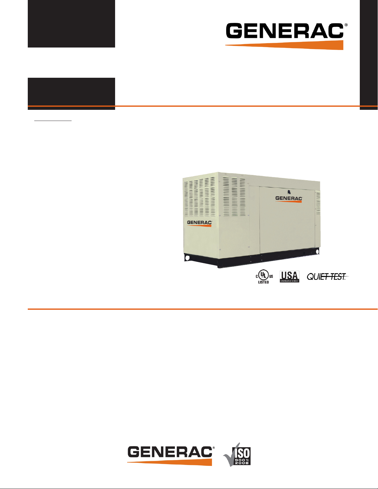
Standby Generators
Liquid-Cooled Gas Engine
Standby Generators
1 of 9
INCLUDES:
• Two Line LCD Tri-Lingual Digital Nexus™
Controller
• Isochronous Electronic Governor
• Sound Attenuated Enclosure
• Closed Coolant Recovery System
• Smart Battery Charger
• UV/Ozone Resistant Hoses
• ±1% Voltage Regulation
• Natural Gas or LP Operation
• 2 Year Limited Warranty
• UL 2200 Listed
70, 100, 130 & 150 kW meet CA/MA emissions requirement with optional catalyst
Standby Power Rating
Model QT070 (Aluminum - Bisque) - 70 kW 60 Hz
Model QT080 (Aluminum - Bisque) - 80 kW 60 Hz
Model QT100 (Aluminum - Bisque) - 100 kW 60 Hz
Model QT130 (Aluminum - Bisque) - 130 kW 60 Hz
Model QT150 (Aluminum - Bisque) - 150 kW 60 Hz
Meets EPA Emission Regulations
80 kW not for sale in CA/MA
FEATURES
¡ INNOVATIVE DESIGN & PROTOTYPE TESTING are key components of
GENERAC’S success in “IMPROVING POWER BY DESIGN.” But it
doesn’t stop there. Total commitment to component testing, reliability
testing, environmental testing, destruction and life testing, plus testing
to applicable CSA, NEMA, EGSA, and other standards, allows you to
choose GENERAC POWER SYSTEMS with the confidence that these
systems will provide superior performance.
¡ TEST CRITERIA:
PROTOTYPE TESTED NEMA MG1-22 EVALUATION
SYSTEM TORSIONAL TESTED MOTOR STARTING ABILITY
¡ SOLID-STATE, FREQUENCY COMPENSATED VOLTAGE REGULATION.
This state-of-the-art power maximizing regulation system is standard on
all Generac models. It provides optimized FAST RESPONSE to changing
load conditions and MAXIMUM MOTOR STARTING CAPABILITY by
electronically torque-matching the surge loads to the engine. Digital
voltage regulation at ±1%.
¡ SINGLE SOURCE SERVICE RESPONSE from Generac’s extensive dealer
network provides parts and service know-how for the entire unit, from the
engine to the smallest electronic component.
¡ GENERAC TRANSFER SWITCHES. Long life and reliability are
synonymous with GENERAC POWER SYSTEMS. One reason for this
confidence is that the GENERAC product line includes its own transfer
systems and controls for total system compatibility.
Page 2
70 • 80 • 100 • 130 • 150 kW application & engineering data
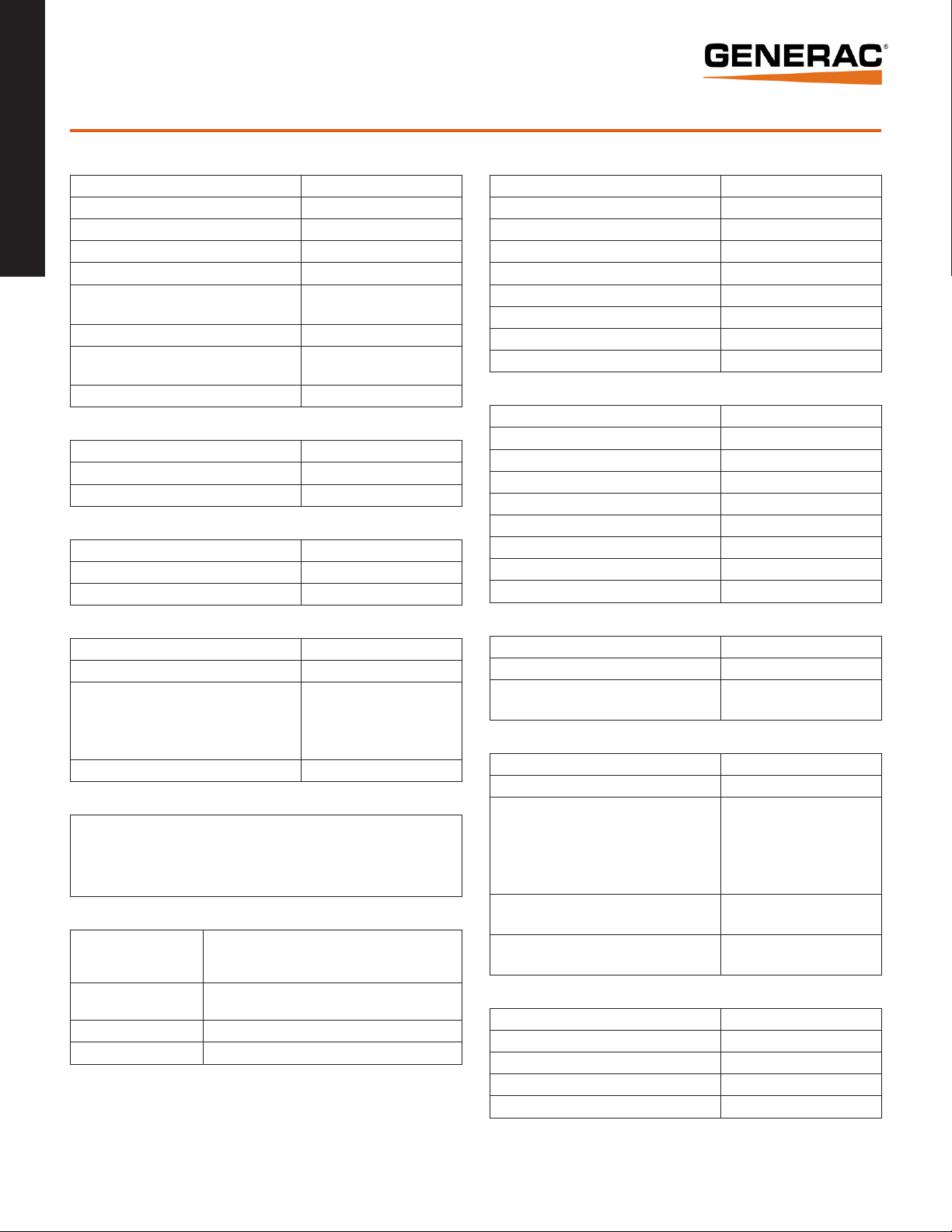
GENERATOR SPECIFICATIONS
Type Synchronous
Rotor Insulation Class H
Standby Generators
2 of 9
Stator Insulation Class H
Telephone Interference Factor (TIF) <50
Alternator Output Leads 1-Phase 4 wire
Alternator Output Leads 3-Phase
Bearings Sealed Ball
Coupling
Excitation System Brushless
VOLTAGE REGULATION
Type Electronic
Sensing Single Phase
Regulation ± 1%
GOVERNOR SPECIFICATIONS
Type Electronic
Frequency Regulation Isochronous
Steady State Regulation ± 0.25%
6 wire (70, 80 & 150 kW) or
12 wire (100 & 130 kW)
Flexible Disc (70, 80 & 150 kW)
or Gear Drive (100 & 130 kW)
ENGINE SPECIFICATIONS: 80 kW
Make Generac
Model V-Type
Cylinders 8
Displacement (Liters) 4.6
Bore (in/mm) 3.55/90.2
Stroke (in/mm) 3.54/89.9
Compression Ratio 9.4:1
Intake Air System Naturally Aspirated
Lifter Type Hydraulic
ENGINE SPECIFICATIONS: 70, 100, 130 & 150 kW
Make Generac
Model V-Type
Cylinders 10
Displacement (Liters) 6.8
Bore (in/mm) 3.55/90.2
Stroke (in/mm) 4.17/105.9
Compression Ratio 9:1
Intake Air System Naturally Aspirated
Lifter Type Hydraulic
ELECTRICAL SYSTEM
Battery Charge Alternator 12 Volt 30 Amp
Static Battery Charger 2 Amp
Group 24F, 525 CCA
Recommended Battery
System Voltage 12 Volts
(70, 80 & 150 kW)
or Group 27F, 700 CCA
(100 & 130 kW)
GENERATOR FEATURES
Revolving field heavy duty generator
Directly connected to the engine
Operating temperature rise 120 °C above a 40 °C ambient
Class H insulation is rated at 150 °C rise at 25 °C ambient
All models fully prototyped tested
ENCLOSURE FEATURES
Aluminum weather
protective enclosure
Enclosed critical grade
muffler
Small, compact, attractive Makes for an easy, eye appealing installation.
SAE Sound attenuated enclosure ensures quiet operation.
Ensures protection against mother nature.
Electrostatically applied textured epoxy paint for added
durability.
Quiet, critical grade muffler is mounted inside the unit
to prevent injuries.
ENGINE LUBRICATION SYSTEM
Oil Pump Type Gear
Oil Filter Type Full flow spin-on cartridge
Crankcase Capacity (quarts/liters)
5/4.7 (70, 100, 130 & 150 kW)
or 6/5.7 (80 kW)
ENGINE COOLING SYSTEM
Type Closed
Water Pump Belt driven
2300 - 70 kW
1600 - 80 kW
Fan Speed (rpm)
Fan Diameter (in/mm)
Fan Mode
26/660.4 (80, 100, 130 & 150 kW)
Puller (80, 100, 130 & 150 kW)
1670 - 100 kW
1950 - 130 kW
2200 - 150 kW
22/558.8 (70 kW) or
Pusher (70 kW) or
FUEL SYSTEM
Fuel Type Natural gas, propane vapor
Carburetor Down Draft
Secondary Fuel Regulator Standard
Fuel Shut Off Solenoid Standard
Operating Fuel Pressure 11” - 14” H2O
(All ratings in accordance with BS5514, ISO3046, ISO8528, SAE J1349 and DIN6271)
Page 3
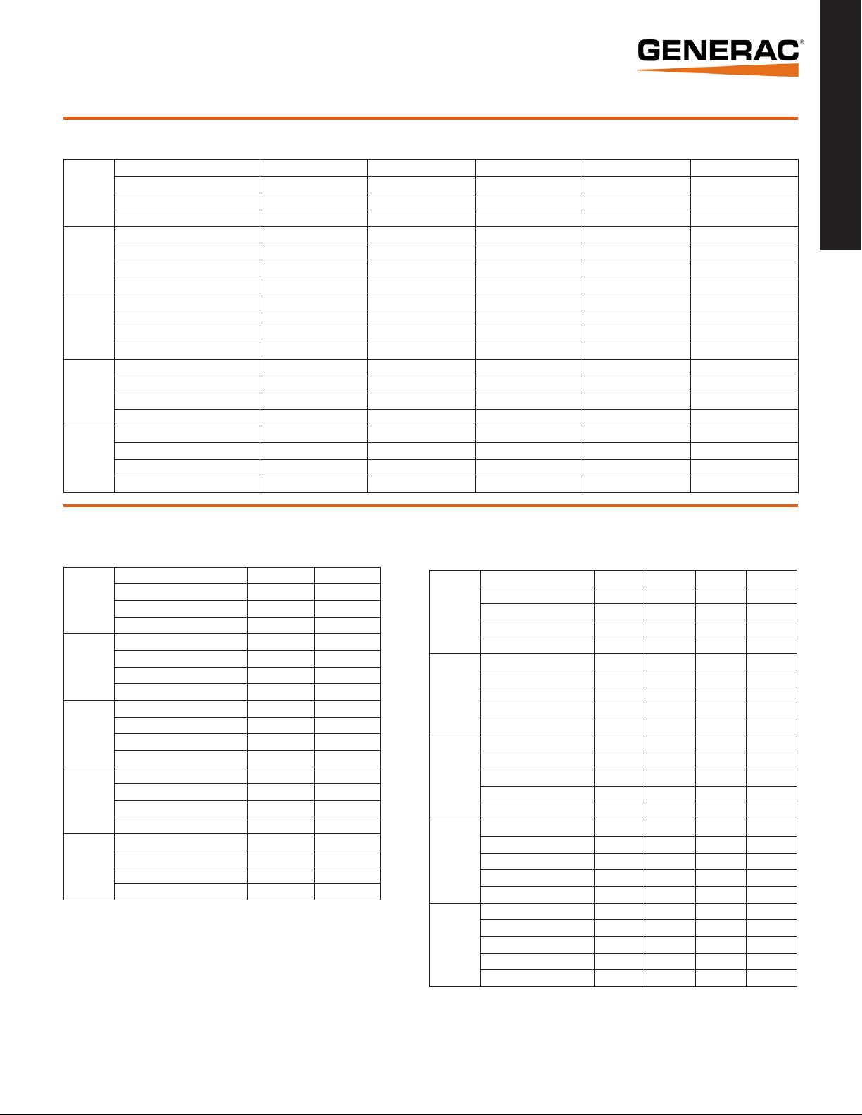
70 • 80 • 100 • 130 • 150 kW operating data
GENERATOR OUTPUT VOLTAGE/kW - 60Hz
kW LPG Amp LPG kW Nat. Gas Amp Nat. Gas CB Size (Both)
120/240 V, 1Ø, 1.0 pf 67 292 64 267 300
QT070
QT080
QT100
QT130
QT150
120/208 V, 3Ø, 0.8 pf 70 243 67 232 300
120/240 V, 3Ø, 0.8 pf 70 211 67 201 250
277/480 V, 3Ø, 0.8 pf 70 105 67 101 125
120/240 V, 1Ø, 1.0 pf 77 333 77 333 400
120/208 V, 3Ø, 0.8 pf 80 278 80 278 300
120/240 V, 3Ø, 0.8 pf 80 241 80 240 300
277/480 V, 3Ø, 0.8 pf 80 120 80 120 150
120/240 V, 1Ø, 1.0 pf 100 417 89 371 500
120/208 V, 3Ø, 0.8 pf 100 347 94 326 400
120/240 V, 3Ø, 0.8 pf 100 301 94 283 350
277/480 V, 3Ø, 0.8 pf 100 150 94 141 175
120/240 V, 1Ø, 1.0 pf 130 542 117 488 600
120/208 V, 3Ø, 0.8 pf 130 451 122 423 500
120/240 V, 3Ø, 0.8 pf 130 391 122 367 450
277/480 V, 3Ø, 0.8 pf 130 195 122 183 225
120/240 V, 1Ø, 1.0 pf 144 625 136 567 700
120/208 V, 3Ø, 0.8 pf 150 520 142 493 600
120/240 V, 3Ø, 0.8 pf 150 451 142 427 500
277/480 V, 3Ø, 0.8 pf 150 225 142 214 250
Standby Generators
3 of 9
SURGE CAPACITY IN AMPS
Voltage Dip @ < .4 pf
15% 30%
120/240 V, 1Ø 129 356
QT070
QT080
QT100
QT130
QT150
Note: Fuel pipe must be sized for full load.
For Btu content, multiply ft3/hr x 2520 (LP) or ft3/hr x 1000 (NG).
For megajoule content, multiple m³/hr x 93.89 (LP) or m³/hr x 37.26 (NG).
Refer to "Emissions Data Sheets" for maximum fuel flow for EPA and SCAQMD permitting purposes.
STANDBY RATING: Standby ratings apply to installations served by a reliable utility source. The standby rating is applicable to varying loads for the duration of a power outage. There
is no overload capability for this rating. Ratings are in accordance with ISO-3046-1. Design and specifications are subject to change without notice.
120/208 V, 3Ø 194 471
120/240 V, 3Ø 168 408
277/480 V, 3Ø 83 201
120/240 V, 1Ø 174 435
120/208 V, 3Ø 186 466
120/240 V, 3Ø 161 404
277/480 V, 3Ø 70 175
120/240 V, 1Ø 150 413
120/208 V, 3Ø 186 452
120/240 V, 3Ø 161 392
277/480 V, 3Ø 107 261
120/240 V, 1Ø 236 648
120/208 V, 3Ø 364 885
120/240 V, 3Ø 315 767
277/480 V, 3Ø 161 390
120/240 V, 1Ø 486 1214
120/208 V, 3Ø 534 1334
120/240 V, 3Ø 463 1156
277/480 V, 3Ø 250 624
ENGINE FUEL CONSUMPTION
Exercise cycle 110 3.1 1.2 4.6
25% of rated load 260 7.4 2.85 10.8
QT070
QT080
QT100
QT130
QT150
50% of rated load 500 14.2 5.46 20.8
75% of rated load 696 19.8 7.62 29.1
100% of rated load 1020 29 11.17 42.6
Exercise cycle 131 3.7 1.45 5.5
25% of rated load 312 8.9 3.45 13.1
50% of rated load 600 17.1 6.64 25
75% of rated load 835 23.7 9.25 34.9
100% of rated load 1154 32.8 12.78 48.2
Exercise cycle 130 3.7 1.4 5.4
25% of rated load 371 10.5 4.1 15.5
50% of rated load 713 20.3 7.9 29.8
75% of rated load 991 28.2 11 41.5
100% of rated load 1260 35.8 13.9 52.6
Exercise cycle 135 3.8 1.4 5.7
25% of rated load 482 13.7 5.3 20
50% of rated load 927 26.3 10.3 38.7
75% of rated load 1292 36.7 14.3 54
100% of rated load 1786 50.8 19.8 74.6
Exercise cycle 155 4.4 1.7 6.5
25% of rated load 556 15.8 6.09 23.2
50% of rated load 1070 30.4 11.72 44.7
75% of rated load 1491 42.4 16.33 62.3
100% of rated load 2061 58.6 22.57 86.1
Natural Gas Propane
(ft³/hr) (m³/hr) (gal/hr) (l/hr)
Page 4

70 • 80 • 100 • 130 • 150 kW operating data
ENGINE COOLING
Air flow (inlet air including alternator and combustion air in ft³/min) 5200/147.2 5300/150.1 5500/155.7 6450/182.6 7800/220.9
Standby Generators
System coolant capacity (gal/liters) 4.5/17 4/15.1 4.5/17 4.5/17 4.5/17
4 of 9
Heat rejection to coolant (BTU/hr) 287,000/302.8 316,000/333.4 342,000/360.8 496,000/523.3 568,000/599.3
Maximum operation air temperature on radiator (°C/°F) 60/150
Maximum ambient temperature (°C/°F) 50/140
COMBUSTION REQUIREMENTS
Flow at rated power (cfm/cmm) 205/5.8 250/7.1 262/7.4 336/9.5 410/11.6
SOUND EMISSIONS
Sound output in dB(A) at 23 ft (7 m) with generator in exercise mode* 67 64 61 65 66
Sound output in dB(A) at 23 ft (7 m) with generator operating at normal load* 72 74 72 75 79
*Sound levels are taken from the front of the generator. Sound levels taken from other sides of the generator may be higher depending on installation parameters.
EXHAUST
Exhaust flow at rated output (cfm/cmm) 557/15.8 720/20.4 888/25.1 1119/31.7 1535/43.5
Exhaust temperature at muffler outlet (°C/°F) 477/890 449/840 516/960 521/970 593/1100
70 kW 80 kW 100 kW 130 kW 150 kW
ENGINE PARAMETERS
Rated Synchronous rpm 1800 3600 2300 2970 3600
POWER ADJUSTMENT FOR AMBIENT CONDITIONS
Temperature Deration ...........................................................................................................3% for every 10 °C above 25 °C or 1.65% for every 10 °F above 77 °F
Altitude Deration (70,100,130 & 150) .................................................................................1% for every 100 m above 183 m or 3% for every 1000 ft above 600 ft
Altitude Deration (80 kW) ................................................................................................ 1% for every 100 m above 915 m or 3% for every 1000 ft above 3000 ft
CONTROLLER FEATURES
2-Line Plain Text LCD Display ........................................................................................................................................Simple user interface for ease of operation.
Mode Switch: Auto ..............................................................................................................................................Automatic Start on Utility failure. 7 day exerciser
Off ...........................................................................................................................Stops unit. Power is removed. Control and charger still operate.
Manual ......................................................................................... Start with starter control, unit stays on. If utility fails, transfer to load takes place.
Programmable start delay between 10-30 seconds ............................................................................................................................................................ Standard
Engine Start Sequence ..................................................................................................................... Cyclic cranking: 16 sec on, 7 rest (90 sec maximum duration)
Engine Warm-up ..................................................................................................................................................................................................................... 5 sec
Engine Cool-Down ..................................................................................................................................................................................................................1 min
Starter Lock-out ................................................................................................................................Starter cannot re-engage until 5 sec after engine has stopped.
Smart Battery Charger ........................................................................................................................................................................................................ Standard
Automatic Voltage Regulation with Over and Under Voltage Protection ................................................................................................................................ Standard
Automatic Low Oil Pressure Shutdown ............................................................................................................................................................................... Standard
Overspeed Shutdown .............................................................................................................................................................................................. Standard, 72 Hz
High Temperature Shutdown ............................................................................................................................................................................................... Standard
Overcrank Protection ..........................................................................................................................................................................................................Standard
Safety Fused ...................................................................................................................................................................................................................... Standard
Failure to Transfer Protection .............................................................................................................................................................................................. Standard
Low Battery Protection ........................................................................................................................................................................................................ Standard
50 Event Run Log ...............................................................................................................................................................................................................Standard
Future Set Capable Exerciser .............................................................................................................................................................................................. Standard
Incorrect Wiring Protection ................................................................................................................................................................................................. Standard
Internal Fault Protection .....................................................................................................................................................................................................Standard
Common External Fault Capability ...................................................................................................................................................................................... Standard
Governor Failure Protection ................................................................................................................................................................................................ Standard
Page 5

70 • 80 • 100 • 130 • 150 kW available accessories
Model # Product Description
005632-0 - 70, 80 & 150 kW
005633-0 - 100 & 130 kW
005620-0 - 70, 100 & 130 kW
005619-0 - 80 kW
005667-0 - 150 kW
005651-0 Base Plug Kit Add base plugs to the base of the generator to keep out debris.
005703-0 Paint Kit
005660-0 - 70, 100, 130 & 150 kW
005985-0 - 80 kW
005928-0 Wireless Remote
005951-0
Cold Weather Kit
Extreme Cold Weather
Kit
Scheduled
Maintenance Kit
Advanced Wireless
Remote
If the temperature regularly falls below 32 °F (0 °C), install a cold
weather kit to maintain optimal battery temperature. Kit consists of
battery warmer with thermostat built into the wrap.
Recommended where the temperature regularly falls below 32 °F (0 °C)
for extended periods of time. For liquid cooled units only.
If the generator enclosure is scratched or damaged, it is important
to touch-up the paint to protect from future corrosion. The paint
kit includes the necessary paint to properly maintain or touch-up a
generator enclosure.
The Liquid-Cooled Scheduled Maintenance Kits offer all the hardware
necessary to perform complete maintenance on Generac liquid-cooled
generators.
Completely wireless and battery powered, Generac's wireless remote
monitor provides you with instant status information without ever
leaving the house.
Remotely control generator functions with the advanced model’s LCD
display. In addition to remote testing of the generator, set the exercise
cycle and maintenance interval reminders.
Standby Generators
5 of 9
006199-0 PMM Starter Kit
006186-0
006463-0 Mobile Link™
006478-0 Harness Adapter Kit
Power Management
Module (50 Amps)
The PMM Starter Kit consists of a 24 VAC, field installed transformer
that enables the use of the 24 VAC Power Management Modules
(PMMs) and one PMM. The standard controller (without starter kit) can
control two HVAC loads with no additional hardware. Not compatible
with pre-wired switches.
Power Management Modules are used in conjunction with the Smart
Switch to increase its power management capabilities. It gives the
Smart Switch additional power management flexibility not found in any
other transfer switch. Not compatible with pre-wired switches. Note:
PMM Starter Kit required.
Generac's Mobile Link allows you to check the status of your generator
from anywhere that you have access to an Internet connection from a
PC or with any smart device. You will even be notified when a change in
the generator’s status occurs via e-mail or text message. Note: Harness
Adapter Kit required.
The Harness Adapter Kit is required to make liquid-cooled units
compatible with Mobile Link™.
Page 6

70 • 80 • 100 • 130 • 150 kW interconnections
Standby Generators
6 of 9
Page 7

70 kW installation layout
Standby Generators
7 of 9
Page 8

80 kW installation layout
Standby Generators
8 of 9
Page 9

100 • 130 • 150 kW installation layout
Standby Generators
9 of 9
Generac Power Systems, Inc. • S45 W29290 HWY. 59, Waukesha, WI 53189 • generac.com
©2013 Generac Power Systems, Inc. All rights reserved. All specifications are subject to change without notice. Bulletin 0199370SBY-B Printed in U.S.A. 07/30/13
 Loading...