

Generac 1652-0 Owner’s Manual
Owner's Manual
". | _,
Generator
Wheel kit
Engine oil
Locking 20 Amp plug
Locking 30 Amp plug
Owner's manual
Engine manual
If any parts are missing or damaged, call 1-800-270-1408.
SafetyRules.................................... 2-3
Assembly...................................... 4-5
Know Your Generator ............................. 6
Operation ..................................... 7-9
Product Specifications............................. 10
Maintenance.................................... I0
Storage........................................ I0
Notes ...................................... I 1-12
Troubleshooting ................................. 13
Schematic...................................... 14
Wiring Diagram ................................. 15
Replacement Parts............................. 16-19
Warranty ................................. Last Page
Questions? Help is just a moment away!
Call:Generac Generator Helpline - 1-800-270-1408 M-F 8-5 CT
Web: www.generac-portables.com or www.briggsandstratton.com
This isthe safety alert symbol. It isusedto alert you to potential personal injury hazards.
Obey all safety messagesthat follow this symbol to avoid possible injury or death.
EQUIPMENT
SAFETY RULES
DESCRIPTION
This generator isan engine-driven, revolving field,
alternating current (AC) generator.It was designedto
supply electrical power for operating compatible electrical
lighting, appliances,tools andmotor loads.
This manualcontains information for a generator that
operates 120and/or 240Volt, single phase,60 Hz devices
that require upto 4,200 watts (4.2 kW) of power that pull
up to 35Amps at 120Volts or 17.5Amps at 240Votts
CAUTION! Do Not exceed the generator's
wattage/amperage capacity.Add up the rated watts of all
devices you are connecting to generator receptacles at one
time.This total should not begreater than 4,200 watts. See
"Don't Overload the Generator" on page 9.
The generator's revolving field is driven at about 3,600 rpm
by a single-cylinder engine.
Every effort hasbeen madeto ensure that informationin
this manualisaccurate and current However, Generac
reservesthe right to change,alter or otherwise improvethe
product andthis document at any time without prior
notice.
This generator set was designed and manufactured for
specific applications. Do Not attempt to modify the unitor
use it for anyapplication it was not designedfor.If you have
anyquestions about your generator's application, askyour
dealer or consult the factory.
The manufacturer could not possibly anticipate every
circumstance that might involvea hazard.For that reason
warnings in the manualand warnings on tags or decals
affixed to the unit are not all-inclusive. If you intendto
handle,operate or service the unit by a procedure or
method not specifically recommended by the manufacturer,
first make sure that such a procedure or method will not
render this equipment unsafeor pose a threat to you and
others.
Read this manual carefully and become familiar
with your generator set. Know its applications, its
limitations and any hazards involved.
or other re
_ AUTION! Do Not tamper with engine
The Emission Control System for this generator is
warranted for standards set by the Environmental
Protection Agency.For warranty informationrefer to the
engine owner's manual.
governed speed.High operating speeds are
dangerousand increaserisk of personal injuryor
damageto equipment.The generator supplies
correct rated frequency andvoltage only when
running at proper governed speed.Incorrect
frequency and/or voltage can damagesome
connected electrical loads.Operating at excessively
low speedsimposesa heavy load.When adequate
engine power isnot availableengine life may be
shortened.
_ ARNING! You must isolatethe generator
from the electric utility usingapproved transfer
equipment ifthis unit isused for backup power.
Failure to isolate the generator from the
power utility may result in injury or death to
electric utility workers and damage to the
generator due to a backfeed of electrical energy.
Whenever the unit is providing backuppower,the
electric utility must be notified.
_ DANGER! Generator exhaust gases contain
DEADLY carbon monoxide gas. If breathed in
sumcient concentrations, carbon monoxide
can cause unconsciousness or death. Operate
this equipment outdoors where adequate ventilation
is available.
• The generator produces avery powerful voltage that can
cause serious injury or death by electrocution. Never
touch barewires or receptacles.Never permit achild or
any unqualified person to operate the generator.
• Never handleany kind of electrical cord or devicewhile
standing in water, while barefoot or while hands or feet
are wet Death or serious injury from electrocution may
result.
• Use a ground fault circuit interrupter (GFCI) in any damp
or highly conductive area (such as metal decking or steel
work).
• Never useworn, bare,frayed or otherwise damaged
electrical cords with the generator. Death, serious injury
and property damagefrom electrical shock may result
• Gasoline is highly FLAMMABLE and its vapors are
EXPLOSIVE. Never allow smoking, open flames,
sparks or heat in the vicinity while handling
gasoline. Avoid spilling gasoline on a hot engine. Comply
with all laws regulating storage and handlingof gasoline.
• Do Not overfitl the fuel tank.Always allow room for fuel
expansion.If tank is overfllled, fuel can overflow
onto a hot engine and cause a FIRE or an
EXPLOSION.
• Never store a generator with fuel in the tank where
gasolinevapors might reach an open flame, spark or pilot
light (ason a furnace, water heater,clothes dryer). FIRE
or an EXPLOSION may result.
• The unit requires an adequateflow of cooling air for its
continued proper operation. Never operate the unit
inside anyroom or enclosure where the free flow of
cooling air into and out of the unit might be obstructed.
Allow at least2 feet of clearanceon all sidesof generator,
evenwhile operating unit outdoors, or you could damage
the unit
• Never start, or stop the unit with electrical loads
connected to receptacles with the connected devices
turned ON. Start the engine and let it stabilize before
connecting any electrical loads. Disconnect all electrical
loads before shutting down the generator.
• Do Not insert any object through cooling slots of the
engine.Youcould damagethe unit or injure yourself.
• Never operate the generator:
in rain; in any enclosed compartment; when connected
electrical devices overheat; if electrical output is lost; if
engine or generator sparks; if flame or smoke is observed
while unit is running; if unit vibrates excessively.
GROUNDING THE
G EN ERATO R
The National Electrical Code requires that the frame and
external electrically conductive parts of this generator be
properly connected to an approved earth ground. Local
electrical codes may also require proper grounding of the
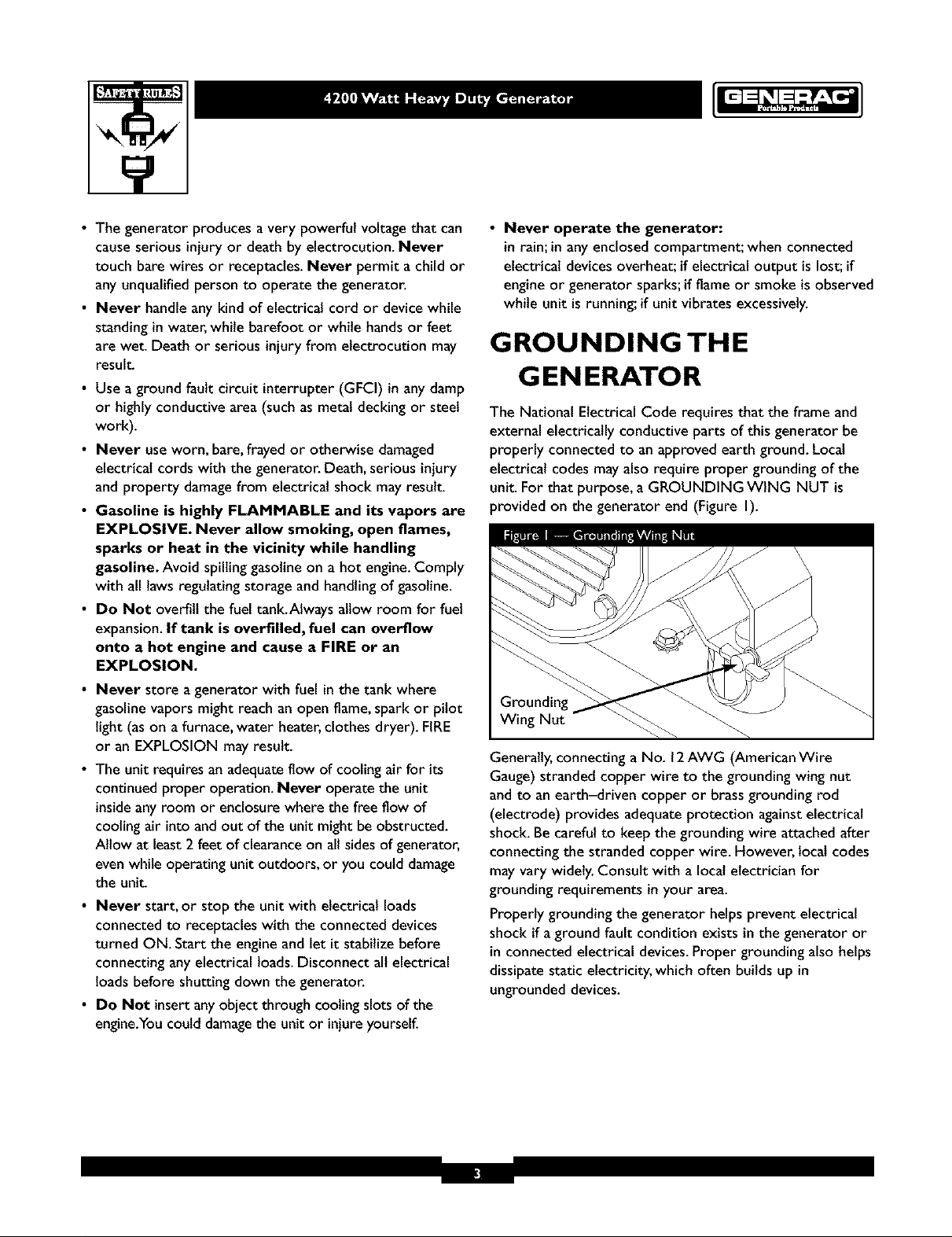
unit. For that purpose, a GROUNDING WING NUT is
provided on the generator end (Figure I).
Wing Nut
Generally,connecting a No. 12AWG (American Wire
Gauge) stranded copper wire to the grounding wing nut
and to an earth-driven copper or brassgrounding rod
(electrode) provides adequateprotection againstelectrical
shock. Be careful to keep the grounding wire attached after
connecting the stranded copper wire. However, locat codes
may vary widely. Consult with a local electrician for
grounding requirements in your area.
Properly grounding the generator helps prevent electrical
shock if a ground fault condition exists in the generator or
in connected electrical devices.Proper grounding also helps
dissipatestatic electricity, which often builds up in
ungrounded devices.
Yourgeneratorrequiressomeassemblyandisreadyfor
useafterit hasbeenproperlyservicedwiththe
recommendedoilandfuel.
If you have any problems with the assembly of your
generator, please call the generator helpline at
1-800-270-1408.
IMPORTANT: Any attempt to run the unit before it has
been serviced with the recommended oil wilt result in an
engine failure.
REMOVE G EN ERATOR
FROM CARTON
• Set the carton on a rigid flat surface with "This Side Up"
arrows pointing upward.
• Carefully open the top flaps of the shippingcarton.
• Cut clown corners at one end of carton from top to
bottom and lay that side of carton down flat.
• Removeall packing material, carton fillers, etc.
• Removethe generator from the shipping carton.
INSTALL WHEEL KIT
The wheel kit isdesignedto greatly improvethe portability
of your generator.
NOTE:Wheel kit is not intendedfor over-the-road use.
You will need a socket wrench with I/2" or 13mmsockets
and a needle+nosepliers to installthis kit.
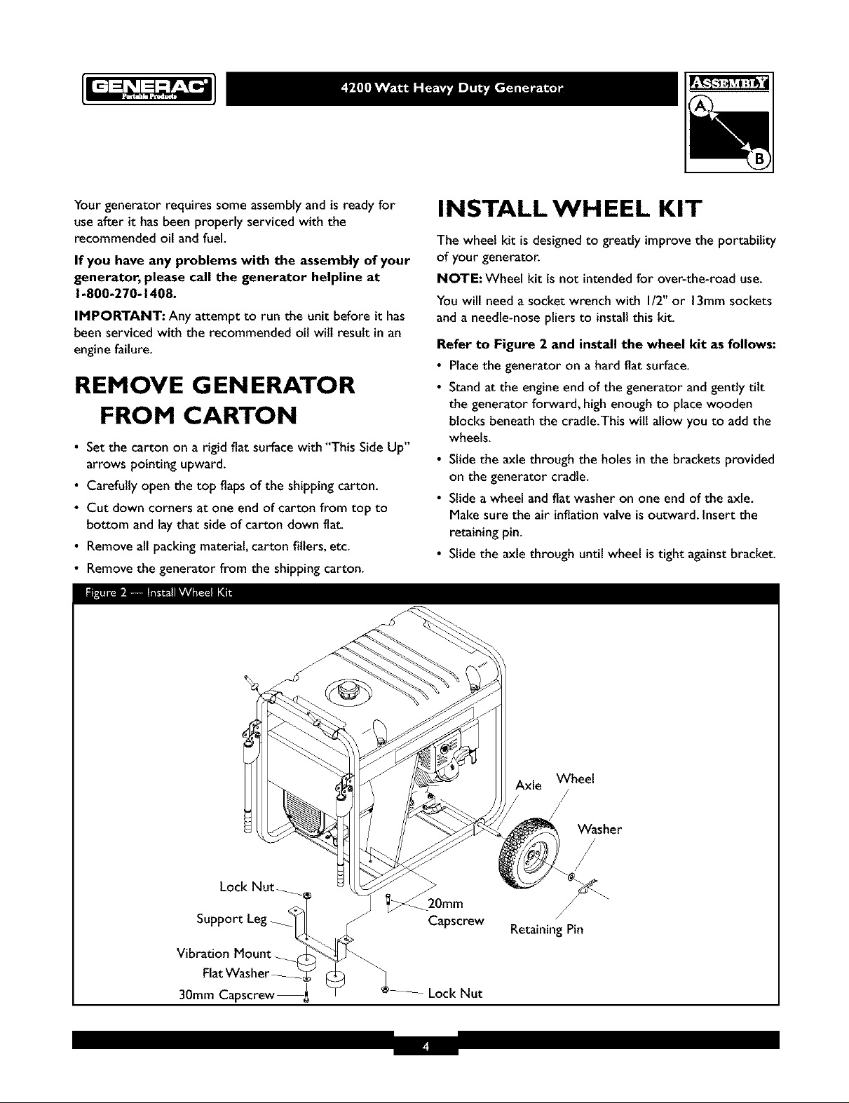
Refer to Figure 2 and install the wheel kit as follows:
• Placethe generator on a hard flat surface.
• Standat the engine end of the generator and gently tilt
the generator forward, high enough to place wooden
blocks beneath the cradle.This will allow you to add the
wheels.
• Slide the axle through the holes in the brackets provided
on the generator cradle.
• Slide a wheel and fiat washer on one end of the axle.
Make sure the air inflation valve isoutward. Insert the
retaining pin.
• Slide the axle through until wheel is tight againstbracket.
Lock Nut_
Support
Vibration Mount_
30mm Capscrew_ Lock Nut
Capscrew
Axle Wheel
Washer
/
Retaining Pin
• Slidetheotherwheelandfiatwasherontheotherend
oftheaxle.Makesuretheairinflationvalveisoutward.
Inserttheretainingpinusingtheneedle-noseplier.
Removethewoodenblocks.
• Attachthevibrationmountstothesupportlegwith
30mmcapscrews,washersandlocknuts.
• Withthewheelson,youcannowtlftupthehandleend
andremovetheexistinghardwarefromtheleftunit
vibrationmountwitha13mmwrench.Usethesame
hardwareto attachthesupportleg.
• Attachtheothersideofthesupportlegwitha20mm
capscrewandlocknut
• Checkeachfastenertoensureitissecureandthetires
areinflatedbetween15-40PSL
BEFORE STARTING THE
ENGINE
Add Oil
CAUTION! Any attempt to crank or start the engine
before it has been properly filled with the recommended
oil mayresult in an engine failure.
To fill your engine with oil:
• Placegenerator on a levelsurface.
• Followthe oil grade recommendations andoil fill
instructionsgiven inthe engine owner's manual.
NOTE= The generator's revolving field rides on a
prelubricated and sealedball bearing that requires no
additional lubricationfor the life of the bearing.
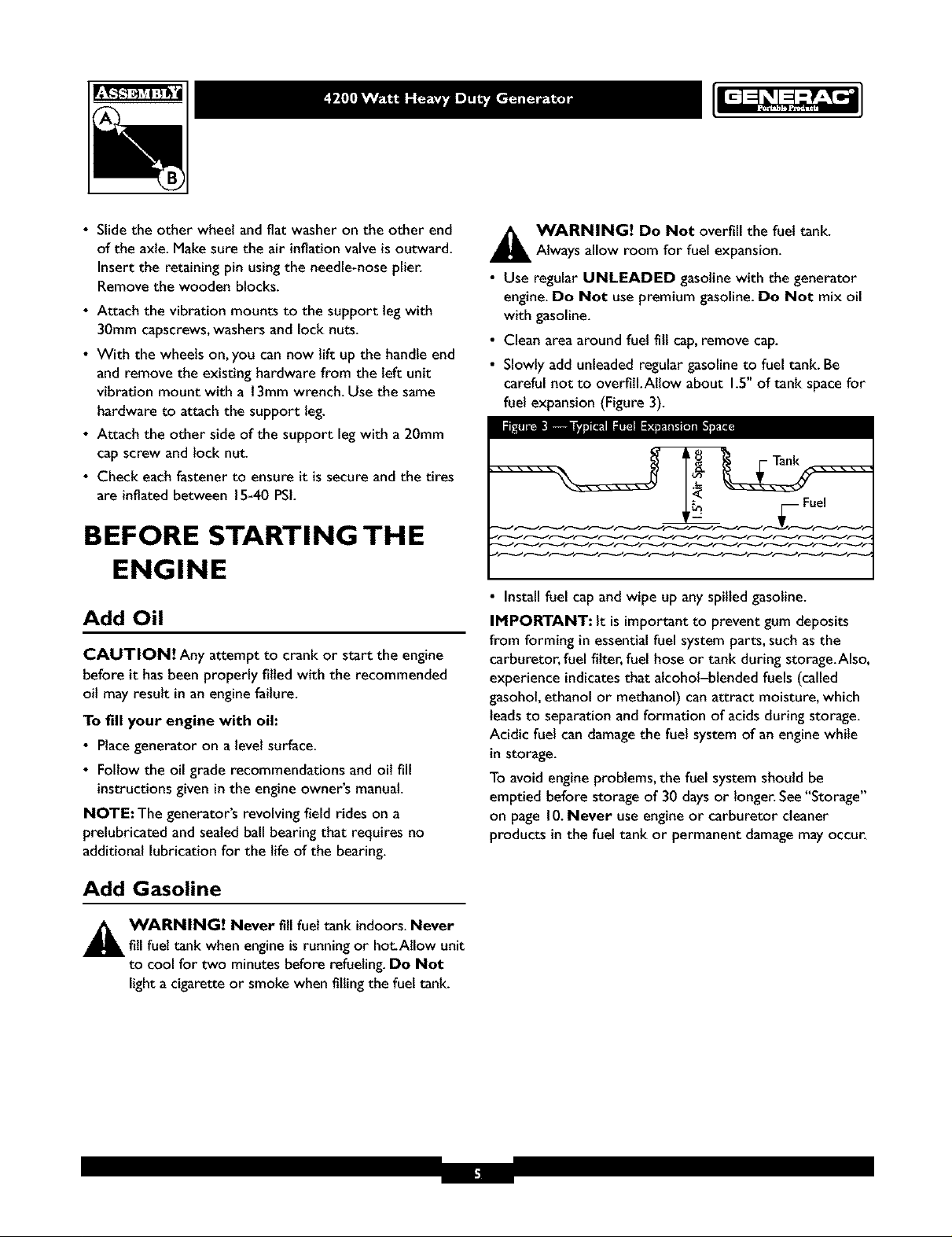
A WARNING! Do Not overfill the fuel tank.
Always allow room for fuel expansion.
• Use regular UNLEADED gasolinewith the generator
engine.Do Not use premium gasoline. Do Not mix oil
with gasoline.
• Clean area around fuel fill cap,remove cap.
• Slowly add unleaded regular gasoline to fuel tank. Be
careful not to overfill.Allow about 1.5"of tank spacefor
fuel expansion (Figure 3).
Fuel
N--NC22N.
• Install fuel cap and wipe up any spilled gasoline.
IMPORTANT: It is important to prevent gum deposits
from forming in essential fuel system parts, such as the
carburetor, fuel filter, fuel hose or tank during storage.Also,
experience indicates that alcohol-blended fuels (called
gasohol, ethanol or methanol) can attract moisture, which
leads to separation and formation of acids during storage.
Acidic fuel can damage the fuel system of an engine while
in storage.
To avoid engine problems, the fuel system should be
emptied before storage of 30 days or longer. See "Storage"
on page 10. Never use engine or carburetor cleaner
products in the fuel tank or permanent damage may occur.
Add Gasoline
A ARNING! Never fill fuel tank indoors. Never
fill fuel tank when engine is running or hot.Allow unit
to cool for two minutes before refueling. Do Not
light a cigarette or smoke when filling the fuel tank.
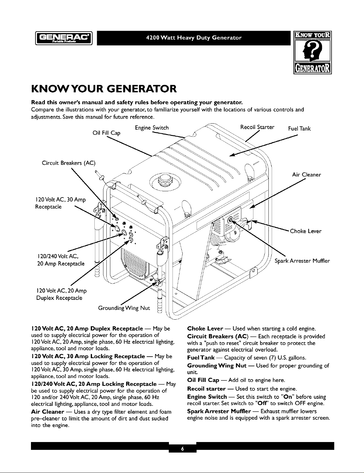
KNOWYOUR GENERATOR
Read this owner's manual and safety rules before operating your generator.
Compare the illustrations with your generator, to familiarize yourself with the locations of various controls and
adjustments. Savethis manualfor future reference.
Circuit Breakers (AC)
\
120Volt AC, 30 Amp
Receptacle
120/240Volt AC,
20 Amp Receptacle
120Volt AC, 20 Amp
Duplex Receptacle
Oil Fill Cap
Grounding Wing Nut
EngineSwitch
Recoil Starter FuelTank
Air Cleaner
SparkArrester Muffler
120Volt AC, 20 Amp Duplex Receptacle -- Maybe
usedto supplyelectrical power for the operation of
120Volt AC, 20Amp, single phase,60 Hz electricallighting,
appliance,tool and motor loads.
120Volt AC, 30 Amp Locking Receptacle -- May be
used to supply electrical power for the operation of
120Volt AC, 30 Amp, single phase,60 Hz electrical lighting,
appliance,toot and motor loads.
120/240 Volt AC, 20 Amp Locking Receptacle -- May
be usedto supply electrical power for the operation of
120and/or 240Volt AC, 20 Amp, single phase,60 Hz
electrical lighting,appliance,tool and motor loads.
Air Cleaner -- Usesa dry type filter element and foam
pre-cleaner to limit the amount of dirt and dust sucked
into the engine.
Choke Lever -- Used when starting a cold engine.
Circuit Breakers (AC) -- Eachreceptacle is provided
with a "push to reset" circuit breaker to protect the
generator againstelectrical overload.
FuelTank -- Capacity of seven(7) U.S.gallons.
GroundingWing Nut -- Usedfor proper grounding of
unit.
Oil Fill Cap --Add oil to engine here.
Recoil starter -- Used to start the engine.
Engine Switch -- Setthis switch to "On" before using
recoil starter. Setswitch to "Off' to switch OFF engine.
Spark Arrester Muffler- Exhaust muffler lowers
engine noise and is equipped with aspark arrester screen.
 Loading...