

Generac 1648-0 Owner’s Manual
Portable Generator Owner's Manual
Questions? Help is just a moment away!
Call:Generac Generator Helpline - 1-800-270-1408 M-F 8-5 CT
Web: www.generac-por tables.corn
Model No. 1648-0 (4,500WattAC Generator) Manual No. 189264GS Revision5 (I 1/19/2002)
EQUIPMENT
DESCRIPTION
_Read this manual carefully and become familiar
with your generator. Know its applications, its
limitations and any hazards involved.
Thisgenerator is an engine-driven, revolving field,alternating
current (AC) generator. It was designedto supply electrical
power for operating compatible electrical lighting,appliances,
tools and motor loads.Thegenerator's revolvingfield is
driven at about 3,600rpm by asingle-cylinderengine.
CAUTION! DO NOT exceed the generator's
wattage/amperage capacity.See"Don't Overload the
Generator" on page I I.
Everyeffort hasbeenmadeto ensure that informationinthis
manualisaccurateandcurrent However,Generac reserves
the right to change,alter or otherwise improvethe product
and this document at anytime without prior notice.
The EmissionControl Systemfor this generator iswarranted
for standardsset by the EnvironmentalProtection Agency.For
warranty informationrefer to the engineowner's manual.
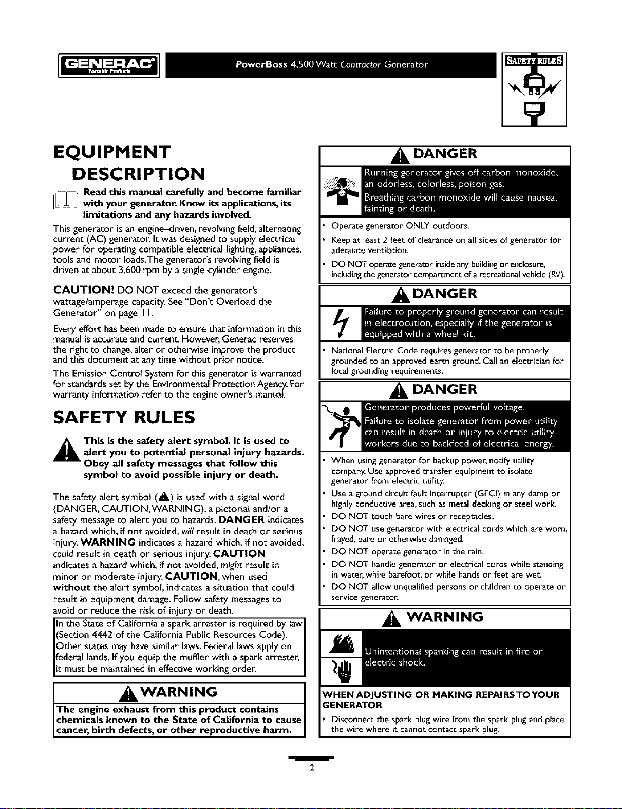
SAFETY RULES
DANGER
Operate generator ONLY outdoors.
Keep at least 2 feet of clearance on all sidesof generator for
adequateventilation.
DO NOT operategenerator insideanybuildingor enclosure,
includingthe generatorcompartment of a recreationalvehicle(RV).
DANGER
National ElectricCode requires generator to be properly
grounded to an approved earth ground. Call an electrician for
local grounding requirements.
DANGER
This is the safety alert symbol. It is used toalert you to potential personal injury hazards.
Obey all safety messages that follow this
symbol to avoid possible injury or death.
The safetyalert symbol (_.) is usedwith a signalword
(DANGER, CAUTION,WARNING), a pictorial and/or a
safety messageto alert you to hazards.DANGER indicates
a hazardwhich, if not avoided,will result in death or serious
injury.WARNING indicatesa hazardwhich, if not avoided,
couldresult in death or serious injury.CAUTION
indicatesa hazardwhich, if not avoided,might result in
minor or moderate injury. CAUTION, when used
without the alert symbol, indicates a situation that could
result in equipment damage.Follow safety messagesto
avoid or reduce the risk of injuryor death.
In the State of California a spark arrester isrequired by lawI
(Section 4442 of the California Public ResourcesCode). I
Other states may havesimilar laws.Federallawsapply on I
federal lands.Ifyou equip the muffler with a spark arrester,
it must be maintained in effective working order.
WARNING
The engine exhaust from this product contains I
chemicals known to the State of California to cause
cancer, b rth defects, or other reproduct ve harm.
When usinggenerator for backup power, notify utility
company.Use approved transfer equipment to isolate
generator from electric utility.
Use aground circuit fault interrupter (GFCI) in any damp or
highly conductive area,such asmetal decking or steel work.
DO NOT touch bare wires or receptacles.
DO NOT use generator with electrical cords which are worn
frayed,bare or otherwise damaged.
DO NOT operate generator in the rain.
DO NOT handle generator or electrical cords while standing
in water, while barefoot, or while handsor feet are wet.
DO NOT allow unqualified persons or children to operate or
service generator.
WARNING
ENERATOR
Disconnect the spark plug wire from the spark plug and place
the wire where it cannot contact spark plug.
/
2
, WARNING
, WARNING
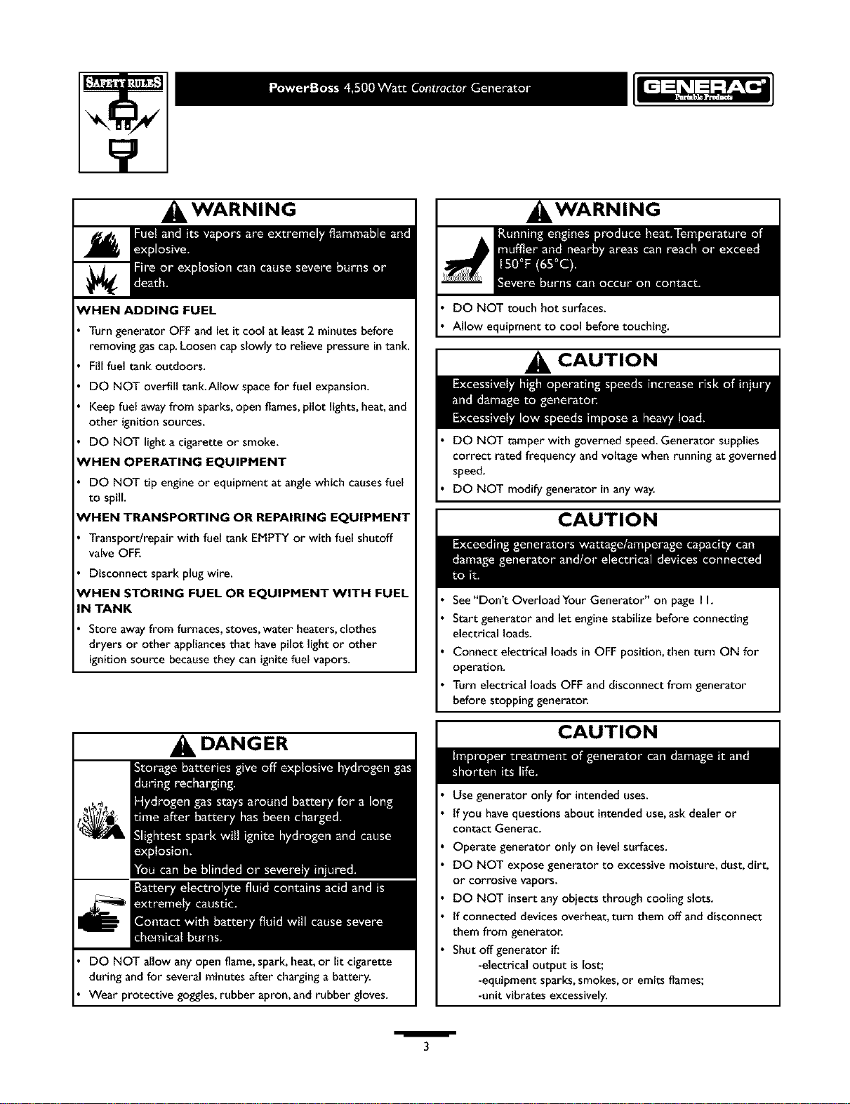
WHEN ADDING FUEL
Turn generator OFF and let it cool at least 2 minutes before
removing gascap.Loosen cap slowly to relieve pressure in tank.
Fill fuel tank outdoors.
DO NOT overfill tank.Allow spacefor fuel expansion.
Keep fuel away from sparks,open flames,pilot lights, heat,and
other ignition sources.
DO NOT light a cigarette or smoke.
NHEN OPERATING EQUIPMENT
DO NOT tip engine or equipment at anglewhich causesfuel
to spill.
'HEN TRANSPORTING OR REPAIRING EQUIPMENT
Transport/repair withfuel tank EMPTYor with fuel shutoff
valve OFF.
Disconnect spark plug wire.
NHEN STORING FUEL OR EQUIPMENT WITH FUEL
IN TANK
Store awayfrom furnaces,stoves, water heaters,clothes
dryers or other appliances that havepilot light or other
ignitionsource becausethey can ignitefuel vapors.
DO NOT touch hot surfaces.
Allow equipment to cool before touching.
CAUTION
DO NOT tamper with governedspeed.Generator supplies
correct rated frequency and voltage when running at governed
speed.
DO NOT modify generator in any way.
CAUTION
See"Don't Overload Your Generator" on page I h
Start generator and let engine stabilize before connecting
electrical loads.
Connect electrical loads in OFF position, then turn ON for
operation.
Turn electrical loads OFF and disconnect from generator
before stopping generator.
DANGER
DO NOT allow any open flame,spark, heat,or lit cigarette
during and for several minutes after charging a battery.
Wear protective goggles,rubber apron, and rubber gloves.
CAUTION
Use generator only for intended uses.
tf you havequestions about intended use,ask dealer or
contact Generac.
Operate generator only on levelsurfaces.
DO NOT expose generator to excessive moisture, dust, dirt,
or corrosive vapors.
DO NOT insert any obiects through cooling slots.
tf connected devices overheat, turn them off and disconnect
them from generaton
Shut off generator if.'
-electrical output is lost;
-equipment sparks,smokes, or emits flames;
-unit vibrates excessively.
/
3
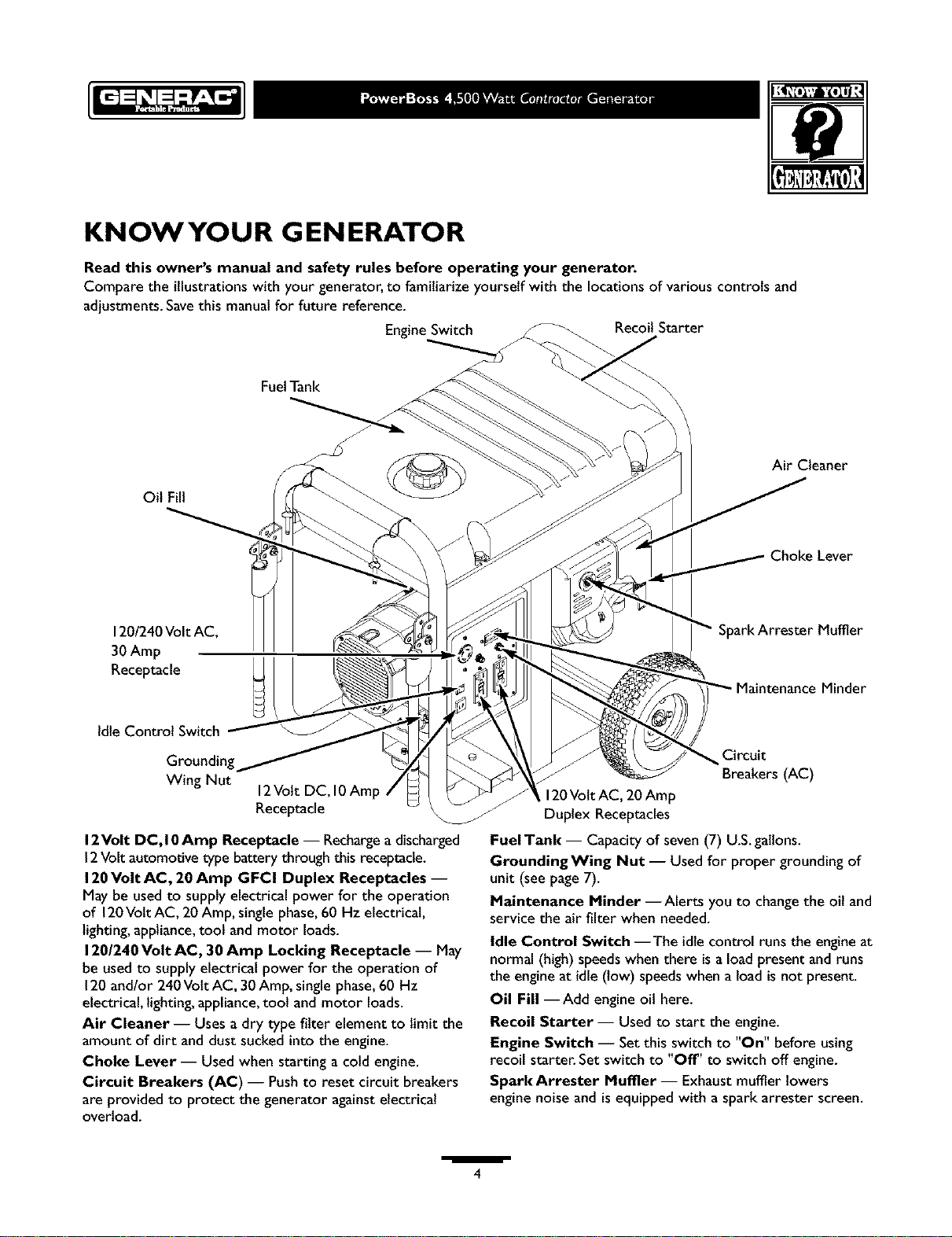
KNOWYOUR GENERATOR
Read this owner's manual and safety rules before operating your generator.
Compare the illustrationswith your generator, to familiarize yourself with the locationsof variouscontrols and
adjustments.Savethis manualfor future reference.
EngineSwitch Recoil Starter
FuelTank
Air Cleaner
Oil Fill
Choke Lever
120/240VoltAC,
30 Amp
Receptacle
Idle Control Switch
Wing Nut
12Volt DC, 10Amp
Receptacle
12Volt DC, I0Amp Receptacle -- Rechargea discharged
12Volt automotive type battery through this receptacle.
120Volt AC, 20 Amp GFCI Duplex Receptacles --
May be usedto supply electrical power for the operation
of 120Volt AC, 20 Amp, single phase,60 Hz electrical,
lighting,appliance,tool and motor loads.
120/240 Volt AC, 30 Amp Locking Receptacle -- May
be usedto supply electrical power for the operation of
120and/or 240Volt AC, 30Amp, single phase,60 Hz
electrical, lighting, appliance,tool and motor loads.
Air Cleaner -- Uses a dry type filter element to limit the
amount of dirt and dust sucked into the engine.
Choke Lever -- Used when starting a cold engine.
Circuit Breakers (AC) -- Pushto reset circuit breakers
are provided to protect the generator againstelectrical
overload.
Spark Attester Muffler
Minder
Circuit
Breakers (AC)
120Volt AC, 20 Amp
Duplex Receptacles
FuelTank -- Capacity of seven (7) U.S.gallons.
GroundingWing Nut -- Used for proper grounding of
unit (see page 7).
Maintenance Minder --Alerts you to change the oil and
service the air filter when needed.
Idle Control Switch --The idlecontrolruns the engineat
normal (high)speedswhen there is aloadpresent and runs
the engineat idle (low) speedswhen a load is not present.
Oil Fill --Add engineoil here.
Recoil Starter-- Used to start the engine.
Engine Switch -- Set this switch to "On" before using
recoil starter. Set switch to "Off" to switch off engine.
Spark Arrester Muffler -- Exhaust muffler lowers
engine noise and is equipped with a spark arrester screen.
/
4
ASSEMBLY
Your generator requires some assembly and isready for
use after it hasbeenproperly serviced with the
recommended oil and fuel.
If you have any problems with the assembly of your
generator, please call the generator helpline at
1-800-270-1408.
Carton Contents
Check allcontents. If any parts are missingor damaged,call
the generator helpline at 1-800-270-1408.
• The generator
• Generator and engine owner's manuals
• Locking 30Amp plug
• Engineoil
• Wheel kit
Remove Generator From Carton
• Set the carton on a rigid fiat surface with "This Side Up"
arrows pointing upward.
• Carefully open the top flaps of the shippingcarton.
• Cut down corners at one end of carton from top to
bottom and lay that side of carton down fiat
• Removeall packingmaterial, carton fillers, etc.
• Removethe generator from the shipping carton.
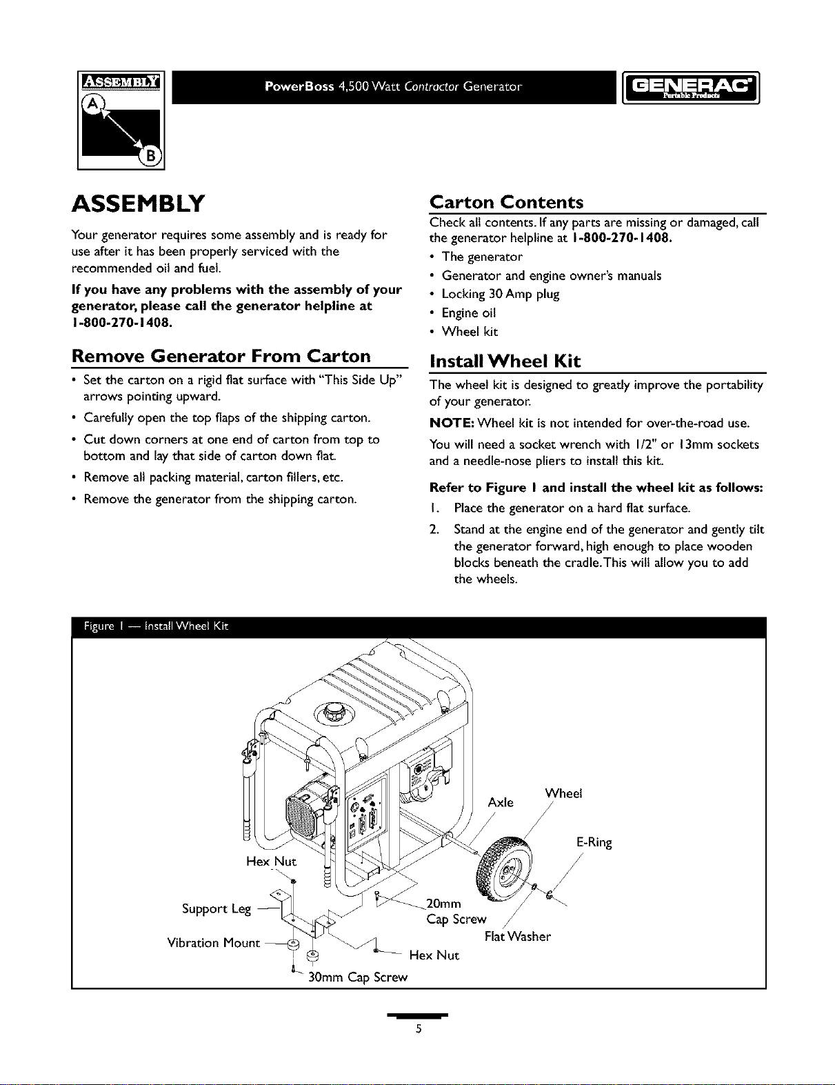
Install Wheel Kit
The wheel kit isdesignedto greatly improvethe portability
of your generator.
NOTE: Wheel kit is not intendedfor over-the-road use.
You will need a socket wrench with I/2" or 13mm sockets
and a needle-nose pliers to install this kit.
Refer to Figure I and install the wheel kit as follows:
I. Placethe generator on a hard fiat surface.
2. Standat the engine end of the generator and gently tilt
the generator forward, high enough to placewooden
blocks beneath the cradle.This will allow you to add
the wheels.
Support Leg
Vibration
Axle /
Wheel
E-Ring
Hex Nut
_20mm
Cap Screw /
FlatWasher
Hex Nut
30mm Cap Screw
/
5
3. Slidethe axle through the holes in the brackets
provided on the generator cradle.
4. Slideawheel and fiat washer over the axle.
NOTE: Be sure to installboth wheels with the air
pressure valve on the outboard side.
5. Placethe e-ring onto the groove in the axle.
NOTE: Use retaining pins insteadof e-clip, if applicable.
6. Placeone end of the needle nose pliers on the bottom
of the axle and the other end of the pliers on top of
the e-ring.Seatthe e-ring by pressing the pliers closed.
7. Repeat step 4 through 6 to secure second wheel
Removethe wooden blocks.
8. Attach the vibration mounts to the support leg with
30mm capscrews,washers and lock nuts.
9. With the wheels on, you can now lift up the handle
end and attach the support leg with 20mm cap screws
and lock nuts.
10. Check eachfastener to ensure it issecure and the
tires are inflated between 15-40 PSI.
BEFORE STARTING THE
Add Fuel
_ ARNING! NEVERfillfuel tank indoors. NEVER
flit fuel tank whenengine isrunningor hot.Allow unit
to cool for two minutes before refueling.DO NOT
light acigarette or smoke when filling the fuel tank.
_ WARNING! DO NOT overfill the fuel tank.
Always allow room for fuel expansion.
• Use regular UNLEADED fuel with the generator
engine.DO NOT usepremium fuel. DO NOT mix oil
with fuel
• Clean area around fuel flit cap,remove cap.
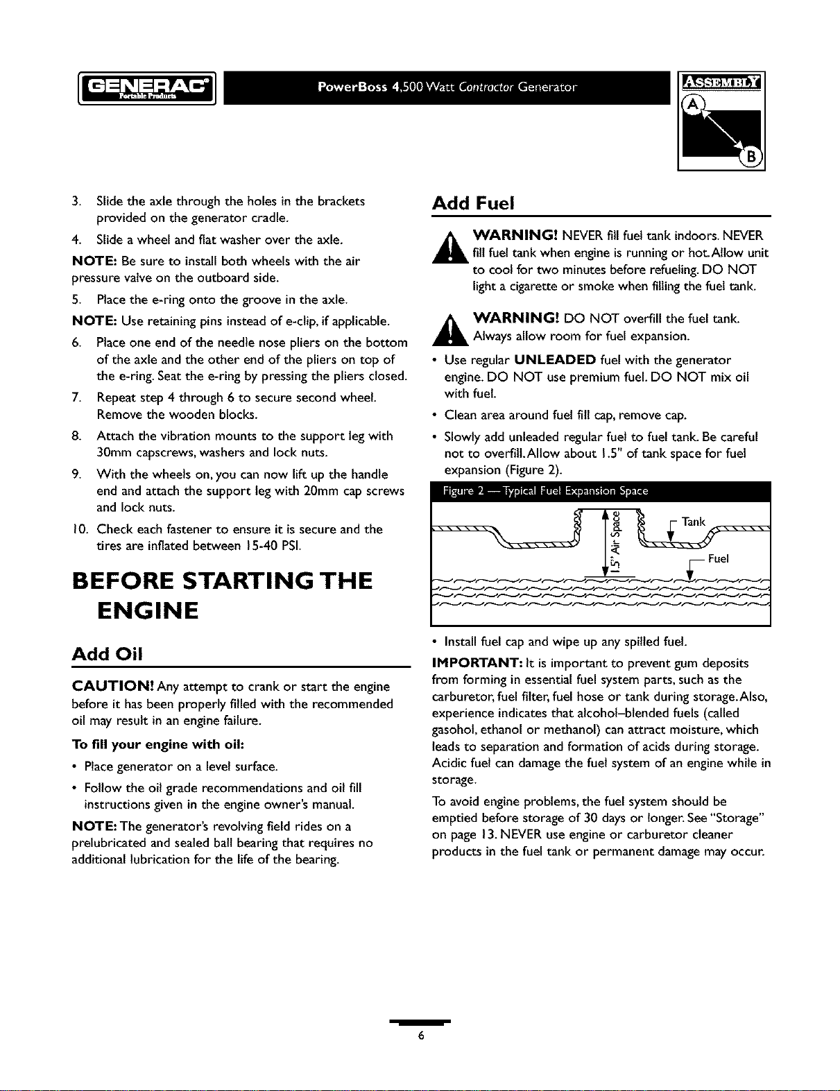
• Slowly addunleaded regular fuel to fuel tank. Be careful
not to overfitLAliow about 1.5"of tank spacefor fuel
expansion (Figure2).
Fuel
..... N--N 22Nr
ENGINE
Add Oil
CAUTION! Any attempt to crank or start the engine
before it hasbeen properly ftled with the recommended
oil may result in an engine failure.
To fill your engine with oil:
• Place generator on a Jevel surface.
• Follow the oil grade recommendationsand oil fill
instructionsgiven in the engine owner's manual.
NOTE:The generator's revolving field rides on a
prelubricated and sealedbait bearing that requires no
additional lubrication for the life of the bearing.
• Install fuel capand wipe up any spilled fuel.
IMPORTANT: It is importantto prevent gum deposits
from forming in essentialfuel system parts,such asthe
carburetor, fuel filter, fuel hose or tank during storage.Also,
experience indicatesthat alcohol-blended fuels (called
gasohol,ethanol or methanol) can attract moisture, which
leadsto separation and formation of acids during storage.
Acidic fuel can damagethe fuel system of an enginewhile in
storage.
To avoid engine problems, the fuel system should be
emptied before storage of 30 claysor longer.See"Storage"
on page 13.NEVERuse engine or carburetor cleaner
products in the fuel tank or permanent damagemay occur.
/
6
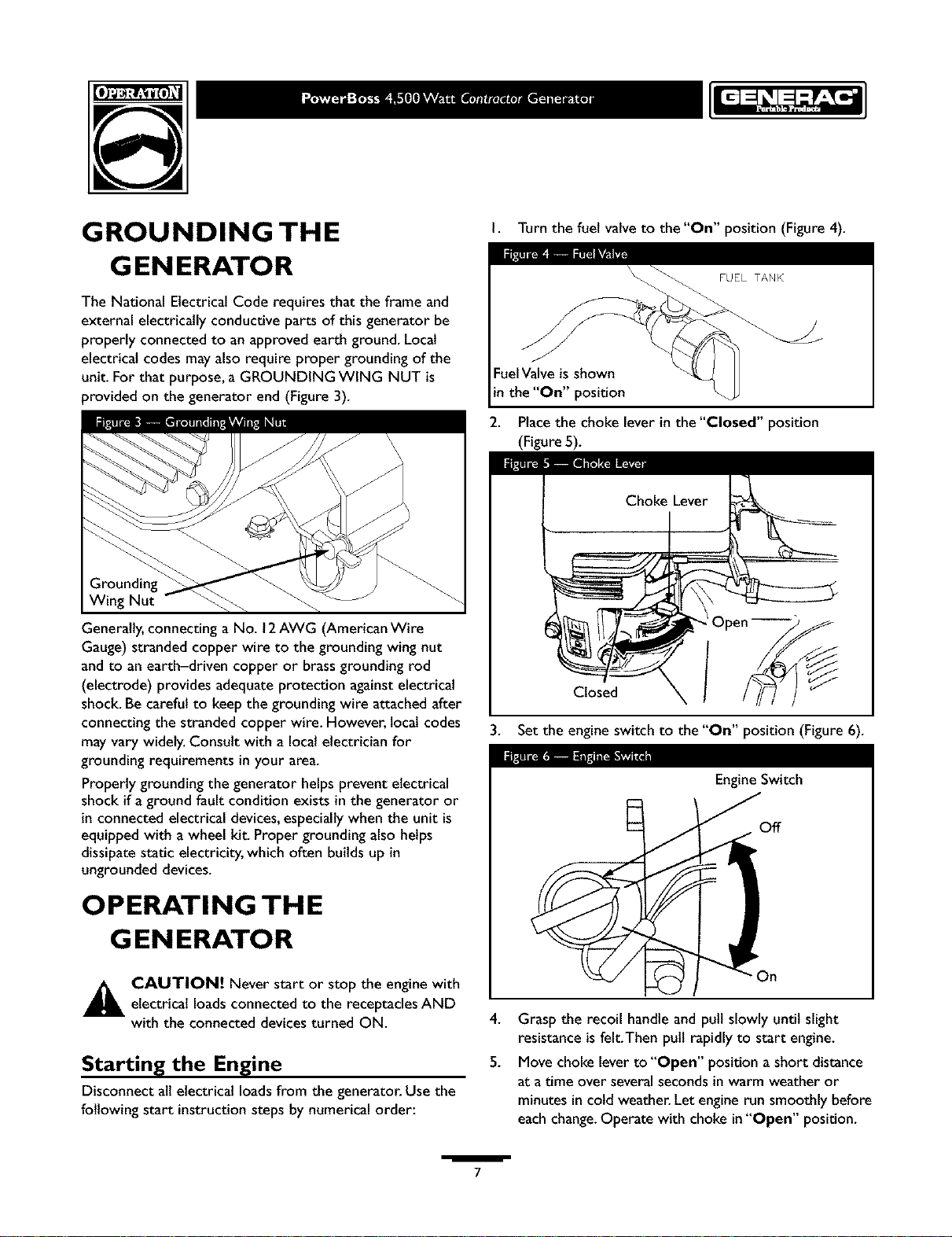
GROUNDING THE
G EN ERATO R
The National Electrical Code requires that the frame and
external electrically conductive parts of this generator be
properly connected to an approved earth ground. Local
electrical codes mayalso require proper grounding of the
unit. For that purpose, a GROUNDING WING NUT is
provided on the generator end (Figure 3).
Wing Nut
Generally,connecting a No. 12AWG (American Wire
Gauge) stranded copper wire to the grounding wing nut
and to an earth-driven copper or brass grounding rod
(electrode) provides adequate protection against electrical
shock. Be careful to keepthe grounding wire attached after
connecting the stranded copper wire. However, local codes
may vary widely.Consult with a localelectrician for
grounding requirements in your area.
Properly grounding the generator helps prevent electrical
shock if aground fault condition exists in the generator or
in connected electrical devices,especiallywhen the unit is
equipped with awheel kit. Proper grounding also helps
dissipate static electricity, which often builds up in
ungrounded devices.
I. Turn the fuel valveto the "On" position (Figure 4).
Fuel Valve is shown
in the "On" position
2.
Placethe chokelever in the "Closed" position
(Figure5).
Closed
.
Setthe engineswitch to the "On" position (Figure6).
EngineSwitch
Off
OPERATING THE
G EN ERATO R
A AUTION! Never start or stop the engine with
Starting the Engine
Disconnect all electrical loadsfrom the generator. Use the
following start instructionsteps by numerical order:
electrical loadsconnected to the receptaclesAND
with the connected devices turned ON.
/
On
4.
Grasp the recoil handle and pull slowly until slight
resistance is felt.Then pull rapidly to start engine.
5.
Move choke lever to "Open" position a short distance
at a time over several seconds in warm weather or
minutes in cold weather. Let engine run smoothly before
each change. Operate with choke in "Open" position.
7
NOTE: If engine still fails to start after 3 pulls,check for
proper oil level in crankcase.This unit is equipped with a
low oil device.Seeengine manual.
Refer to the engine owner's manual for more
detailed starting instructions.
Connecting Electrical Loads
• Let enginestabilize and warm up for a few minutes after
starting.
• Plugin and turn on the desired 120and/or 240 VottAC,
single phase,60 Hz electrical loads.
• DO NOT connect 240Vott loads to the 120Volt duplex
receptacles.
• DO NOT connect 3-phase loads to the generator.
• DO NOT connect 50 Hz loads to the generator.
• DO NOT OVERLOADTHE GENERATOR. See
"Don't Overload the Generator" on page I I.
Stopping the Engine
• Unplug all electrical loads from generator panel
receptacles,NEVER start or stop engine with electrical
devices plugged in and turned ON.
• Let engine run at no-load for several minutes to stabilize
the internal temperatures of engine and generator.
• Move the engine switch to "Off' position.
• Move the fuel valve to the "Off' position.
_ ARNING! DO NOT permit smoking,open
flame,sparks or anyother source of heat around a
battery.Wear protective goggles,rubber apron and
rubber gloves when working around a battery.
Battery electrolyte fluidis an extremely caustic
sulfuric acid solution that can causesevere burns. If
spill occurs flush area with clear water immediately.
Your generator hasthe capability of recharging adischarged
12Volt automotive or utility style storage battery. DO
NOT use the unit to chargeany 6Volt batteries. DO NOT
usethe unit to crank an engine havinga discharged battery.
To recharge 12Volt batteries, proceed as follows:
• Check fluidlevel in all battery cells. If necessary,add
ONLY distilled water to cover separators in battery cells.
DO NOT use tap water.
• If the battery isequipped with vent caps,make sure they
are installed and are tight.
• If necessary,clean battery terminals.
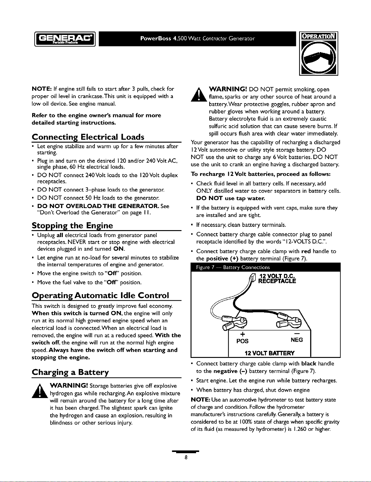
• Connect battery charge cable connector plug to panel
receptacle identified by the words "12-VOLTS D.C".
• Connect battery charge cable clamp with red handle to
the positive (+) battery terminal (Figure7).
12 VOLT D.C.
RECEPTACLE
Operating Automatic Idle Control
This switch is designedto greatly improve fuel economy.
When this switch is turned ON, the engine will only
run at its normal high governed engine speed when an
electrical load is connected.When an electrical load is
removed,the enginewill run at a reduced speed.With the
switch off, the engine will run at the normal high engine
speed.Always have the switch off when starting and
stopping the engine.
Charging a Battery
_ ARNING! Storage batteries give off explosive
hydrogen gas while recharging.An explosive mixture
will remain around the battery for a long time after
it hasbeencharged.The slightest spark can ignite
the hydrogen and causean explosion, resulting in
blindness or other serious injury.
i
+
POS NEG
12 VOLT BA'n'ERY
• Connect battery charge cable clamp with black handle
to the negative (-) battery terminal (Figure7).
• Start engine.Let the engine run while battery recharges.
• When battery hascharged,shut down engine
NOTE: Use an automotive hydrometer to test battery state
of chargeand condition. Follow the hydrometer
manufacturer'sinstructions carefully.Generally,a battery is
consideredto be at 1(30°/ostateof chargewhen specificgravity
of its fluid (asmeasuredby hydrometer) is 1.260or higher.
8
RECEPTACLES
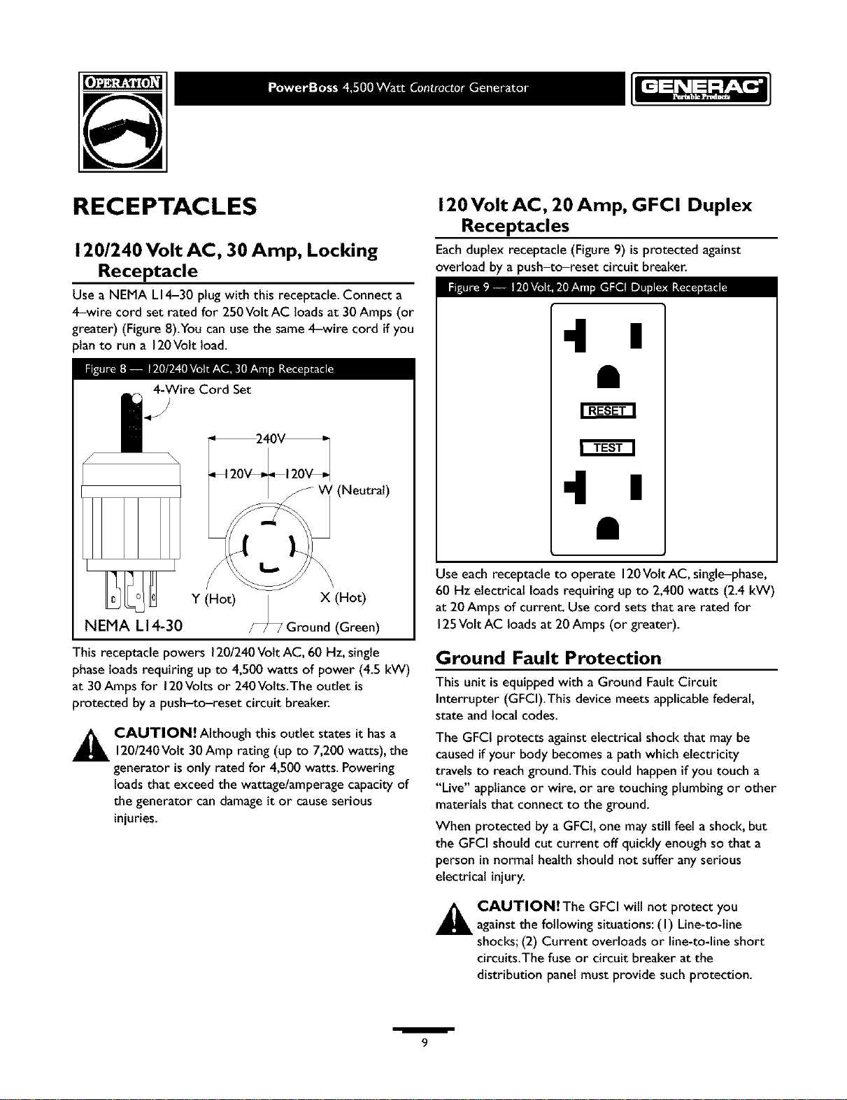
120/240 Volt AC, 30 Amp, Locking
Receptacle
Use a NEMA LI4-30 plug with this receptacle.Connect a
4-wire cord set rated for 250Volt AC loads at 30 Amps (or
greater) (Figure 8).You can usethe same 4-wire cord if you
)lan to run a 120Volt load.
4-WireCord Set
f
120 Volt AC, 20 Amp, GFCI Duplex
Receptacles
Eachduplex receptacle (Figure 9) isprotected against
overload by a push-to-reset circuit breaker.
•11 I
(Neutral)
Y (Hot) | X (Hot)
NEMA L14-30 /--_ Ground(Green)
This receptacle powers 120/240Volt AC, 60 Hz,single
phaseloads requiring up to 4,500 watts of power (4.5 kW)
at 30Amps for 120Volts or 240Volts.The outlet is
protected by a push-to-reset circuit breaker.
_ CAUTION! Although this outlet states it has a
120/240 Volt 30 Amp rating (up to 7,200 watts), the
generator is only rated for 4,500 watts. Powering
loads that exceed the wattage/amperage capacity of
the generator can damage it or cause serious
injuries.
•11 I
Use each receptacle to operate 120Volt AC, single-phase,
60 Hz electrical loadsrequiring up to 2,400 watts (2.4 kW)
at 20Amps of current. Use cord sets that are rated for
125Volt AC loads at 20Amps (or greater).
Ground Fault Protection
Thisunit isequipped with a Ground FaultCircuit
Interrupter (GFCI).This device meets applicablefederal,
state and localcodes.
The GFCI protects againstelectrical shock that may be
caused ifyour body becomes a path which electricity
travels to reach ground.This could happenif you touch a
"Live" applianceor wire, or are touching plumbing or other
materials that connect to the ground.
When protected by a GFCI, one may still feel a shock, but
the GFCI should cut current off quickly enough so that a
person in normal health should not suffer anyserious
electrical injury.
_ CAUTION!The GFCI will not protect you
against the following situations: (I) Line-to-line
shocks;(2) Current overloads or line-to-lineshort
circuits.The fuse or circuit breaker at the
distribution panel must provide such protection.
/
9
Testing the GFCI
Test your GFCI outlet every month, asfollows:
• Pushthe black*'Test" button.The red "Reset" button
should pop out, which should allow no power to reach
the outlet. Use a test lamp in each outlet to test this.
_ AUTION! Ifthe"Reset" button does not pop
out or the test tamp remains lit when the "Reset"
button is popped out, do not useany outlets on the
circuit Call a qualified electrician.
• If the GFCI tests good, restore power by pressingthe
"Reset" button firmly until it isfully in place and locksin
that position. If the GFCI outlet does not reset
properly, do not use the outlet _ call a Generac
service center.
• If the GFCI trips by itselfat anytime, reset and test the
outlet. If the reset button does pop out when the
test button is pressed, do not use the outlet. Call
a Generac service center.
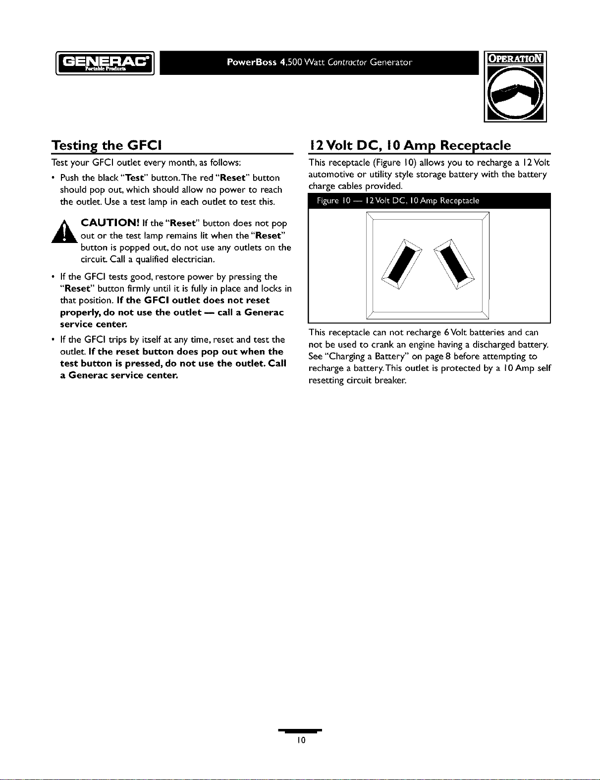
12Volt DC, I 0 Amp Receptacle
This receptacle (Figure10) allows you to recharge a 12Volt
automotive or utility style storage battery with the battery
chargecables provided.
I[o_ IIP_LV_ilDZeelIJ[!]r_]:i _tI
This receptacle can not recharge 6Volt batteries and can
not be usedto crank an engine havingadischargedbattery.
See"Charging a Battery" on page8 before attempting to
recharge a battery.This outlet isprotected by a l0 Amp self
resetting circuit breaker.
/
10
DON'T OVERLOAD YOUR
G EN ERATO R
Capacity
You must make sure your generator cansupply enough
rated (running) and surge (starting) watts for the itemsyou
will power at the sametime. Follow these simple steps:
I. Select the itemsyou wilt power at the sametime.
2. Total the rated (running) watts of these items.Thisis
the amount of power your generator must produce to
keep your items running. SeeFigure I I.
3. Estimate how many surge (starting) watts you wilt
need.Surge wattage isthe short burst of power
needed to start electric motor-driven tools or
appliancessuch asacircular saw or refrigerator.
Becausenot all motors start at the sametime, total
surge watts can be estimated by addingonly the
item(s)with the highest additional surge watts to the
total rated watts from step 2.
Example:
Tool or Appliance
Window Air
Conditioner
Refrigerator
Deep Freezer
Television
Light (75 Watts)
Total Rated (Running)Watts = 3075
Highest Additional SurgeWatts = 1800
Total Generator Output Required = 4875
Rated (Running)
Watts
1200
8O0
50O
50O
75
3075 Total
Running Watts
Power Management
To prolong the life of your generator and attached devices,
it is important to take care when addingelectrical loads to
your generator.There should be nothing connected to the
generator outlets before starting it's engine.The correct
and safeway to managegenerator power isto sequentially
add loads as follows:
I. With nothing connected to the generator, start the
engine asdescribed in this manual
2. Plugin and turn on the first load,preferably the largest
load you have.
3. Permit the generator output to stabilize (engineruns
smoothly and attached device operates properly).
Additional Surge
(Starting)Watts
1800
1600
500
1800 Highest
Surge Watts
4. Plugin and turn on the next load.
5. Again,permit the generator to stabilize.
6. Repeatsteps 4 and 5for each additional load.
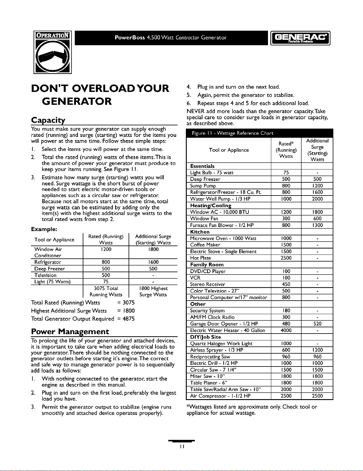
NEVER add more loads than the generator capacity.Take
specialcare to consider surgeloads in generator capacity,
asdescribed above.
Rated*
Tool or Appliance
Essentials
Light Bulb - 75 watt
Deep Freezer
SumpPump
Refrigerator/Freezer - 18Cu. Ft.
Water Well Pump- I/3 HP
Heating/Cooling
Window AC - 10,000 BTU
Window Fan
FurnaceFanBlower - I/2 HP
Kitchen
Microwave Oven - 1000Watt
Coffee Maker
Electric Stove - SingleElement
Hot Plate
Family Room
DVD/CD Player
VCR
Stereo Receiver
Color Television - 27"
Personal Computer w/I 7" monitor
Other
SecuritySystem
AM/FM Clock Radio
GarageDoor Opener - I/2 HP
Electric Water Heater - 40 Gallon
DIY/Job Site
Quartz Halogen Work Light
Airless Sprayer - I/3 HP
Reciprocating Saw
Electric Drill - I/2 HP
Circular Saw- 7 I/4"
Miter Saw - I0"
Table Planer - 6"
Table Saw/RadialArm Saw - I0"
Air Compressor - I-I/2 HP
*Wattages listed are approximate only. Check toot or
appliance for actual wattage.
(Running)
Watts
75
500
8O0
8O0
1000
12O0
3OO
8O0
1000
1500
1500
2500
100
100
450
5o0
8o0
18o
3O0
480 520
40O0
1000
600 1200
960 960
1000 1000
1500 1500
1800 1800
1800 1800
2000 2000
2500 2500
Additional
Surge
(Starting)
Watts
5O0
1200
1600
20O0
1800
6O0
1300
/
II
 Loading...