

Page 1
-------------------
Model: 13694330200
Type:
Engine: D6.
SDI00
7.1
GENERAC®
Owner's
Stationary
Manual
Emergency
Generator
This
manual
should
remain
with
the
c@us
LISTED
unit.
Page 2
Table of Contents
Introduction
Read
This
Manual
Thoroughly
Operation
HowtoObtain
Authorized
Safety
and
Maintenance
Service
Service
Rules
Dealer
Locator
Number
..'
Generallnformation
IDENTIFICATION
Data
Generator
EQUIPMENT
Standard
ENGINE
Coolant
Low
Oil
Pressure
Overs
Overcrank
RPM
DC
FUSES..
FUEL
SYSTEM
Diesel
SPECIFICATIONS
Generator
Engine
Coolant. 6
Gearbox
Fuel
BATTERY
THE
BATTERY...
GENERATORACLEAD
Four-lead,
12-lead,
Six-lead,
FIELD
WIRING
Field
GENERATOR
STARTING
Engine
Engine
Battery
Battery
RECORD
Label
...
Set
XPL
Label
DESCRIPTION
Generator
PROTECTIVE
Temperature
Coolant
peed
Sensor
Fuel
Oil
Lubrication..
System
INSTALLATION..
Broad
600
Wiring
AIDS
Coolant
Oil
Warmers
Chargers..
DEViCES..
Level
Sensor...
Sender
Shutdown
Shutdown
Loss
Shutdown...
System...
Recommendations
Requirements
Single-phase
Range
VAC,
Three-phase
CONNECTIONS
ConnectionstoBuss
AND
LOAD
Heaters..
Heater
(Optional)
(Optional)..
. .
Features
Sender
CONNECTIONS
.
. 5
and
Recommendations.....
Stator..
Stators
Stator
REQUIREMENTS
Bars..
COMPATIBILITY
..
..
. 5
. 5
. 6
. 7
. 7
. 8
.
.
.
.
.
. 6
.....
1
1
1
1
...
1
2
4
.4
.
;)
5
5
Installation
STATIONARY
NFPA
Other
BASIC
EMERGENCY
TOTAL
GROUNDING
GENERATORACNEUTRAL
TRANSFER
BATTERY
Vented
PREPARATION
PriortoInitial
Start-up
EMERGENCY
Standards...
Published
STATIONARY
CIRCUIT
Standards..
EMERGENCY
CIRCUIT
ISOLATION
ISOLATION
THE
GENERATOR...
SWITCH
START
INSTALLATION.....
Batteries.....
BEFORE
Start-up..
Inspection
START-UP
GENERATOR
METHOD
CONNECTIONS..............
SIGNAL
INSTALLATION
ELECTRIC
METHOD
SYSTEM..
.
CONNECTIONS.
. .
..
Operation
0
;)
5
5
6
GENERATOR
OPERATING
Retransfer
OPERATING
CONTROL
UNIT
Start-up
and
UNIT
AND
WITH
MANUAL
and
Transfer...
Shutdown..
WITH
AUTOMATIC
OPERATION
TRANSFER
TRANSFER
SWITCH
SWITCH
Maintenance
10
10
11
11
11
11
11
12
12
6
6
6
8
8
9
SERVICE
PERIODIC
REPAIR
500
SERVICE
Notes
Warranty
SCHEDULE..............
Authorized
Authorized
Test
and
Inspect
Check
Inspect
Inspect/Test
HowtoOrder
I\VV
ENGINE
Operator
Service
MAINTENANCE
Stationary
PARTS........
TO
Emergency
Components..
Battery...
Fluids.
Exhaust
System..
Fuel
Supply
Parts..
600
I\VV
DRIVEN
GENERATOR
MAINTENANCE
Maintenance
Technician
. . 19
STATIONARY
INTERVAL
Maintenance
Generator
System..
EMERGENCY
SETS..
Functions
Functions
System
Operation
.. ..
.
DIESEL
.
INFORMATION
..
13
.13
.
13
...13
.
13
..
14
...14
14
..14
.
14
14
.
.15
..
15
...15
..
16
16
16
...16
16
.,..17
....
17
17
.
17
17
.
17
18
.
18
..
18
..
19
19
19
.
19
..
20
,,20
27
29
Page 3
INTRODUCTION
Thank
you
for
purchasing
generator
Every
instructionsinthis
time
the
any
READ
If
est
procedures.
Throughout
generator,
usedtoalert
serviceoroperation
rectlyorcarelessly.
as
INDICATESAHAZARDOUS
NOT
set
product
effort
was
the
manual
righttochange,
time
without
THIS
MANUAL
any
portionofthis
Authorized
this
DANGER,
personneltospecial
follows:
AVOIDED,
expendedtomake
was
prior
Service
publication,
WILL
Indicatesahazardous
avoided,
could
Indicatesahazardous
avoided,
Notes
and
willbefound
These
indicate.
instructions
preventing
Four
commonly
WARNING
indicatesisas
contain
safety
Common
while
accidents.
and
could
additional
warnings
used
CAUTION
follows:
this
linebyGenerac
manual
written.
alterorotherwise
notice.
THOROUGHLY
manualisnot
Dealer
WARNING,
that
maybehazardousifperformed
Observe
~
RESULTINDEATHORSERIOUS
IAWARNING!I
resultindeathorserious
ACAUTIONI
resultinminorormoderate
within
the
cannot
sense
performing
safety
modelofthe
were
both
However,
for
starting,
andontags
CAUTION
instructions
them
SITUATIONORACTION
stationary
Power
Systems,
sure
that
the
accurate
the
manufacturer
improve
understood,
operating
and
decals
and
carefully.
Their
situationoraction
situationoraction
NOTE:
information
regular
and
strict
the
symbols
blocks.
importanttoa
text
bodyofthis
eliminate
actionorservice
the
compliance
accompany
The
typeofinformation
emergency
Inc"
information
and
currentatthe
this
product(s)
contact
and
affixedtothe
NOTE
aboutaparticular
definitions
WHICH,
reserves
the
near-
servicing
blocks
incor-
INJURY.
and
at
are
are
IF
which,ifnot
injury.
which,ifnot
injury.
procedure
manual.
hazards
with
are
that
the
essential
the
DANGER,
they
special
to
each
The
operatorisresponsible
ment.
The
manufacturer
read
this
Owner's
tions
before
recommends
the
unit.
This
inanemergency.
OPERATION
Itisthe
make
promptly,
an
replacementofparts
and,assuch,
ship
and
Proper
numberofproblems
SeeanAuthorized
sories.
Operating
stationary
Authorized
Installationofthis
operator's
sure
Authorized
within
usage
maintenance
instructions
HOWTOOBTAIN
When
the
Authorized
factory-trained
When
contactinganAuthorized
service,
as
affixedtothe
always
givenonthe
Manual
using
this
instructing
prepares
AND
MAINTENANCE
responsibilitytoperform
that
all
maintenance
andtohave
Service
are
not
the
termsofthe
contributetothe
emergency
Service
Dealerorother
equipmentisnota"do-it-yourself"
SERVICE
generator
Service
and
front
unit.
Dealer
are
supply
for
proper
strongly
equipment.
other
themifthey
the
Dealer.
are
the
considered
and
careofthe
and
keep
Service
presentedinthis
electric
requires
capableofhandling
the
coverofthis
recommends
and
thoroughly
The
userstoproperly
needtooperate
for
equipment
Normal
responsibilityofthe
defectsinmaterialsorworkman-
warranty.
need
for
operating
Dealer
system
competent,
servicingorrepairs,
for
assistance.
Service
complete
manualoron
Introduction
and
safe
useofthe
that
understand
manufacturer
start
the
all
safety
safe
operationisperformed
checked
maintenance
Individual
maintenance
generator
expensesata
for
service
manual
has
Service
Dealer
model
periodically
owner/operator
operating
service.
ensureaminimum
aids
assume
been
installedbyan
qualified
technicians
all
service
about
numberofthe
the
equip-
the
operator
all
instruc-
also
strongly
and
operate
equipment
checks,
service
habits
minimum.
and
acces-
that
contractor.
project.
contact
needs.
parts
DATA
LABEL
to
by
and
the
an
are
and
unit
A
This
symbol
....ifnot
propertyofothers.
A
This
symbol
£
This
symbol
Lh
This
symbol
points
followed,
points
points
points
out
could
out
out
out
important
endanger
potential
potential
potential
safety
personal
explosion
fire
hazard.
electrical
information
safety
and/or
hazard.
shock
hazard.
that,
AUTHORIZED
DEALER
To
locate
the
nearest
DEALER,
please
SERVICE
LOCATION
AUTHORIZED
call
this
SERVICE
number:
1·800·333·1322
DEALER
LOCATION
CANBEOBTAINEDATTHIS
or
visit
INFORMATION
the
website
NUMBER
at
www.generac.com.
Page 4
Safety Rules
It..
SAVE
THESE INSTRUCTIONS - The manufacturer suggests that these rules for safe operation be
...
copied and posted In potential hazard areas. Safety should be stressed to all operators, potential
operators, and service and repair technicians for this equipment.
It..
SAVE
THESE INSTRUCTIONS - This manual contains Important Instructions that should be followed
"'durlng
Study
these
or
servicing
Manual
ciently
maintained.
and
fundamental
The
manufacturer
that
might
tags
and
If
usingaprocedure,
manufacturer
safe
for
operating
It..
Despite the safe design of this genera·
...
tor, operating this equipment Imprudently,
neglecting Its maintenance or being careless
can cause possible Injury or death. Permit
only responsible and capable persons to
Install, operate or maintain this equipment.
~
Potentially lethal voltages are generated by
~these
render the machine safe before attempting to
work on the generator.
It..
Parts of the generator are rotating and/or hot
...
during operation. Exercise care near running
generators.
•
For
equipmentbeinstalled,
Service
installation
standards
all
such
•
Installation,
equipment
dards,
national
the
established.
ed
and
tions
that
aforementioned
Installation and maintenance of the generator and batteries.
SAFETY
this
and
with
and
reliably
Many
involveahazard.
decals
others.
technique
RULES
equipment.
the
onlyifitisproperly
accidents
rulesorprecautions.
cannot
affixedtothe
work
does
not
Also
utilized
carefully
Become
unit.
The
are
anticipate
The
unit
methodoroperating
specifically
make
sure
does
before
installing,
familiar
generator
causedbyfailingtofollow
every
warningsinthis
are,
therefore,
recommend,
the
procedure,
not
render
with
can
operate
installed,
possible
technique
the
generator
this
safely,
operated
circumstance
not
all-inclusive.
ensure
work
operating
Owner's
effi-
and
simple
and
that
thatitis
method
unsafe.
on
the
or
~
machines. Ensure all steps are taken to
GENERAL
safety
reasons,
Dealerorother
technician
and
codes,
operation,
must
laws
and
electrical
Occupational
Also,
servicedinaccordance
and
recommendations.
might
render
the
regulations.
standards
always
regulat'lons.
and
Safety
ensure
the
unit
codes,
HAZARDS
manufacturer
serviced
whoisfamiliar
servicing
building
and
standards,
and
competent,
The
operator
and
regulations.
and
comply
that
with
Adhere
codes.
Health
the
generatorisinstalled,
with
Following
unsafeorin
Administration
the
laws
recommends
repairedbyan
qualified
with
applicable
also
must
of
this
applicable
strictlytolocal,
Comply
manufacturer's
installation,donothing
noncompliance
and
regulations.
Authorized
electrician
comply
(and
codes,
with
regulations
(OSHA)
that
related)
state
operat-
instrucwith
this
or
codes,
with
stan-
and
has
the
•
The
engine
which
sufficient
death.
Exhaust
enclosure
animals,
installed
and
standards.
•
Keep
and
other
fan
guard
•
Adequate,
criticalinany
buildupofexplosive
operation.Donot
blockageofventilation
safe
•
Keep
Remove
•
When
Never
fatigued.
•
Inspect
all
worn,
approved
•
Before
nect
its
the
cable
or
•
Never
on
the
gerous
leakage,
exhaust
canbeDEADLY.
concentrations,
For
that
reason,
gases
mustbepiped
that
houses
etc.,
will
properly,instrict
hands,
feet,
movingorhot
while
unobstructed
roomorbuilding
operationofthe
the
area
any
materials
workingonthis
workonthe
the
generator
damagedordefective
parts.
performing
battery
cablestoprevent
from
the
first.
Reconnect
use
the
generatororanyofits
unit
can
operating
oil
leakage,
fumes
This
can
adequate
the
generatortoan
notbeharmed.
compliance
clothing,
parts.
the
unitisoperating.
flowofcooling
gases
alter
the
provisions,asthis
generator.
around
the
that
could
equipment,
equipment
regularly,
any
maintenanceonthe
battery
post
that
cable
stress
and
break
conditions
etc.
contain
safely
etc,
andtoensure
installationorpermit
generator
from
carbon
dangerous
cause
unconsciousnessoreven
ventilation
away
This
exhaust
with
away
from
Never
remove
housing
the
clean
become
remain
when
physicallyormentally
and
promptly
parts
accidental
indicatedbya
last.
partsasa
parts,
and
leaking
monoxide
gas,ifbreathed
mustbeprovided.
from
any
area
where
system
applicable
drive
any
and
ventilating
generatortoprevent
correct
can
seriously
and
hazardous.
alertatall
repairorreplace
using
only
generator,
start-up.
NEGATIVE,
step.
may
resultindan-
exhaust
gas,
building
people,
must
codes
belts,
fans,
drive
belt
air
generator
even
partial
affect
uncluttered.
times.
factory-
discon-
Disconnect
NEG
Stepping
gases,
fuel
in
or
be
or
is
2
Page 5
Safety Rules
ELECTRICAL
•
All
generators
trical
voltages
delivers
switchaswellasthe
contact
generatoraswellasthe
appropriate
ating
the
unit,
standonan
•
Do
not
inginwater,
DANGEROUS
•Ifpeople
operating,
place
insulative
equipment
•
The
generator
National
•
Wire
gauge
mustbeadequatetohandle
(ampacity)towhich
Requirements
•
Before
sure
that
their
source.
sibly
fatal
•
Connecting
byanelectric
to
isolate
distribution
isolate
by
such
also
resultininjuryordeathtoutility
backfeedofelectrical
•
Generators
crank
voltageisremovedoris
prevent
nel,
disable
cables,
a
"Do
the
transfer
•Incaseofaccident
shut
down
sible,
DIRECT
implement,
the
live
and
get
•
Never
can
conduct
caughtinmoving
coveredbythis
and
can
cause
extremely
with
generator.Ifwork
handle
must
Electrical
installingorservicing
all
electrical
the
the
means
and
start
such
etc.)
Not
attempttofree
CONTACT
conductor.Ifthe
immediate
wear
high
bare
Wires,
covers,
guards
insulated,
any
kindofelectrical
while
barefoot,orwhile
ELECTRICAL
standonmetalorconcrete
servicing,
only while
sizesofelectrical
power
Failuretodosowill
this
utility
generator
system
two
installed
automatic
the
before
Operate"
switch.
the
suchasa
jewelry
electricity
adjustingorrepairing
mats
overadry
standingonsuch
set
mustbegroundedinaccordance
Code
they
Table.
voltage
shock.
unittoan
shallbeby
when
electric
will
resultindamagetothe
energy.
withanautomatic
automatically
generator's
workingonor
tagonthe
causedbyelectric
sourceofelectrical
the
WITH
dry
medical
when
components
HAZARDS
manual
produce
fatal
electrical
and
dangerous
stationary
terminals,
transfer
and
barriers
mustbedone
dry
surfacetoreduce
SHOCK
and
any
the
willbesubjected.
this
supplies
electrical
meansofa
electric
the
generatorisoperating.
system
when
belowanacceptable
start-up
automatic
victim
THE
ropeorboard,tofree
victimisunconscious,
help.
workingonthis
resultinginelectric
causing
voltagestothe
emergency
connections,
switch,ifapplicable.
areinplace
aroundanoperating
device
handsorfeet
MAY
RESULT.
wooden
stateorlocal
wiring,
(and
system
power
and
generator
from
VICTIM.
platform.
insulative
cables
maximum
See
related)
are
positively
resultinhazardous
system
transfer
from
sources
power
transfer
NORMAL
possible
start
around
the
control
shock,
power.Ifthisisnot
the
live
Useanonconducting
equipment.
injury.
dangerous
shock.
Utility
transfer
generator.
etc.,onthe
Ensure
before
shock
hazard.
while
are
while
installing,
this
equipment,
Workonthe
mats.
with
requirements.
and
cord
electrical
the
equipment,
normally
the
from
generator
workers
(UTILITY)
preset
injurytopersonunit.
conductor.
shock,ormay
current
Field
turned
and
supplied
switchsoas
electric
Failure
each
and
switch
source
level.
circuit
(battery
Then,
panel
and
immediately
the
victim
apply
first
Jewelry
Wiring
due
AVOID
elec-
power
Avoid
all
oper-
stand-
wet.
the
sets
make
off
at
pos-
utility
to
other
may
to
will
To
place
on
pos-
from
aid
get
•
Keepafire
use
toxic,
extinguisher
there
the
any
and
are
local
extinguisher
carbon
tetra-chloride
the
liquid
properly
any
questions
fire
department.
EXPLOSION
•
Properly
prevent
•
Do
spills
in
FIREorEXPLOSION
generator
•
All
and
ing
system
supply
accordingtoapplicable
equipment
•
Diesel
ventilate
bUild-Upofexplosive
not
smoke
immediately.
the
generator
fuel
types
shOUldbehandled
the
storage
frequently
lines
fuels
CALIFORNIA
Engine
to
the
CALIFORNIA
This
product
StateofCaliforniatocause
any
around
compartment,oronornear
clean
and
are
and
mustbeproperly
into
service,
are
highly
exhaust
StateofCaliforniatocause
and
containsoremits
other
FIRE
HAZARDS
near
the
generatoratall
type
extingUisher,
can
deteriorate
charged
pertainingtofire
wiring
insulation.
andbefamiliar
extinguishers,
HAZARDS
roomorbuilding
gas,
the
generator,
Ensure
thatnocombustible
may
result.
free
from
potentially
handlingoffuels,
and
and
other
FLAMMABLE
with
care,
correct
fuel-gas
FLAMMABLE.
PROPOSITION65WARNING
someofits
reproductive
PROPOSITION65WARNING
reproductive
Keep
debris.
Comply
any
installed,
codes
constituents
cancer,
chemicals
cancer,
harm
housing
Wipeupany
the
area
with
Inspect
leaks
purged
before
harm.
birth
times,DoNOT
Its
fumes
Keep
with
its
the
generator
fueloroil
materials
the
generator,
surrounding
and/or
EXPLOSIVE
all
laws
the
unit's
immediately,
and
leak
placing
are
known
birth
defects
knowntothe
defects
and
are
the
use.
consult
to
are
left
as
the
regulat-
fuel
Fuel
tested
this
If
3
Page 6
General
Information
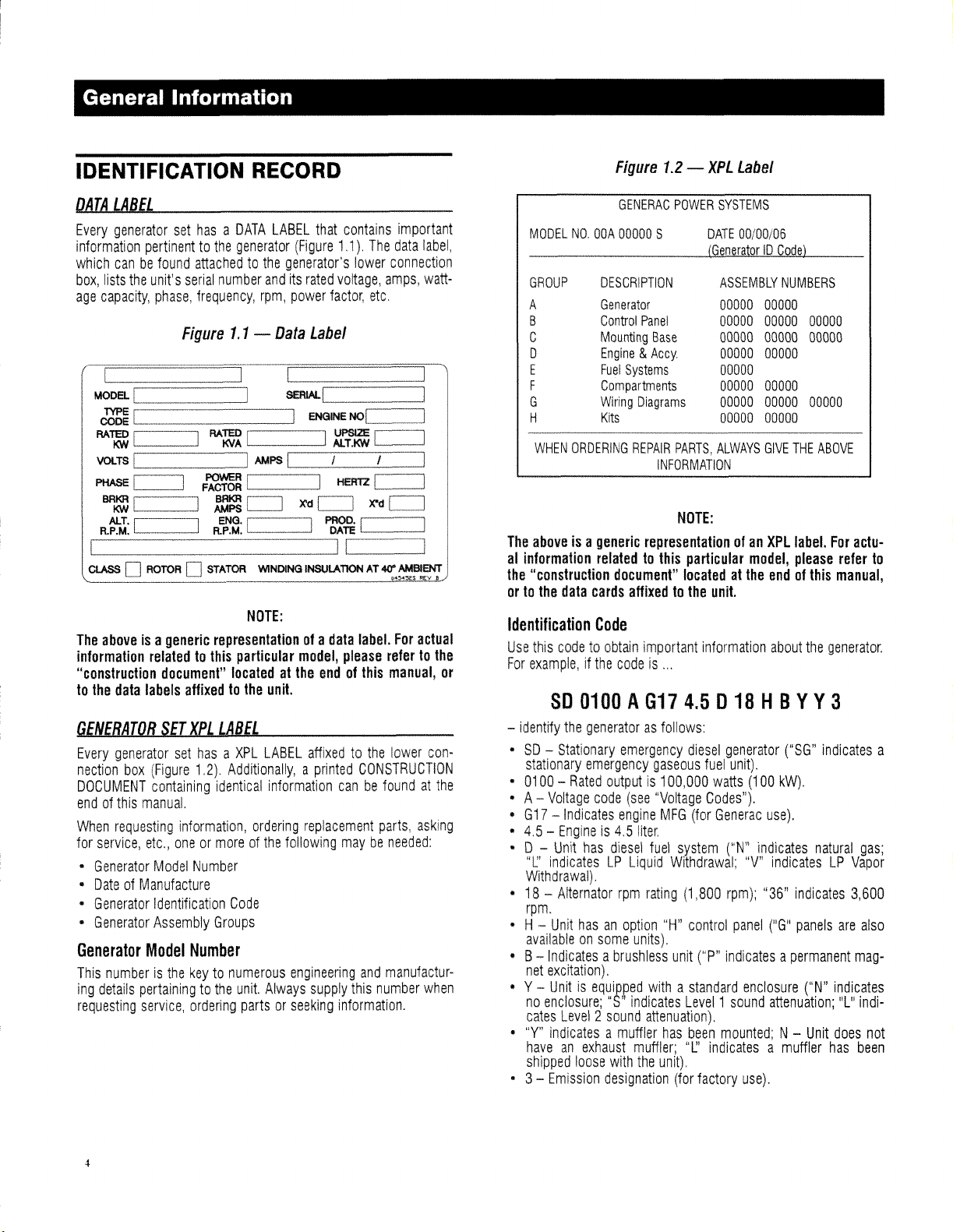
IDENTIFICATION
DATA
LABEL
Every
generator
information
which
canbefound
box,
lists
age
capacity,
The
aboveisa
information
"construction
to
the
data
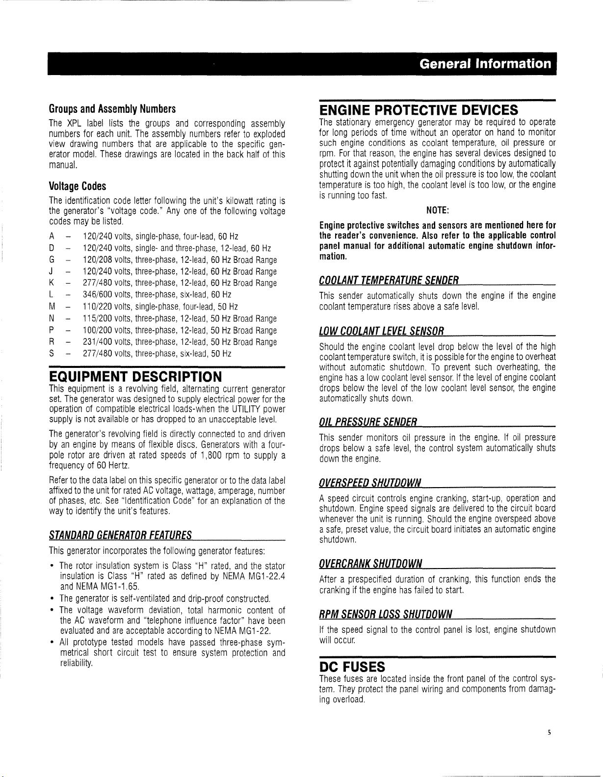
GENERATOR
Every
generator
nection
box
DOCUMENT
endofthis
When
requesting
for
service,
•
Generator
•
DateofManufacture
•
Generator
•
Generator
Generator
This
numberisthe
ing
details
requesting
set
hasaDATA
pertinenttothe
attachedtothe
the
unit's
serial
phase,
frequency,
Figure
generic
relatedtothis
document"
labels
affixedtothe
SET
XPL
set
hasaXPL
(Figure
1,2),
containing
manual.
information,
etc"
oneormoreofthe
Model
Number
Identification
Assembly
Model
Number
keytonumerous
pertainingtothe
service,
ordering
number
1.1
representationofa
locatedatthe
LABEL
Additionally,aprinted
identical
Code
Groups
RECORD
LABEL
that
generator
NOTE:
particular
unit
partsorseeking
(Figure
generator's
and
its
rpm,
power
-
Data
unit.
LABEL
information
ordering
following
engineering
Always
rated
Label
model,
endofthis
affixedtothe
replacement
supply
contains
1,1),
voltage,
factor,
data
please
The
lower
etc
label.
important
data
label,
connection
amps,
watt-
For
actual
refertothe
manual,
lower
CONSTRUCTION
canbefoundatthe
parts,
asking
maybeneeded:
and
manufactur-
this
number
when
information,
or
con-
MODELNOOOA
GROUP
A
B
C
D
E
F
G
H
WHEN
ORDERING
The
aboveisa
al
information
the
"construction
ortothe
Identification
Use
this
For
example,ifthe
-
identify
•SOstationary
•
0100-Rated
• A-
Voltage
•
G17
•
4,5-Engineis4,5
• 0 -
'T'
indicatesLPLiquid
Withdrawal),
•18rpm.
• H-
availableonsome
• B-
Indicatesabrushless
net
excitation).
• Y-
Unitisequipped
no
enclosure;
cates
•
"Y"
indicatesamuffler
haveanexhaust
shipped
• 3-
Emission
generic
relatedtothis
data
cards
Code
codetoobtain
SO
0100A617
the
generatorasfollows:
Stationary
emergency
code
-Indicates
Unit
has
Alternator
Unit
hasanoption
Level2sound
loose
Figure
DESCRIPTION
Generator
Control
Mounting
Engine&Accy,
Fuel
Compartments
Wiring
Kits
1.2
GENERAC
00000
Systems
POWER
S
Panel
Base
Diagrams
REPAIR
PARTS,
INFORMATION
-
NOTE:
representationofan
particular
document"
locatedatthe
affixedtothe
important
codeis'"
4.5018
emergency
outputis100,000
(see
engine
liter.
diesel
rpm
units).
"5'
indicates
muffler;
with
the
designation
diesel
gaseous
"Voltage
MFG
fuel
system
Withdrawal;
rating
(1,800
"H"
control
unit
withastandard
Level1sound
attenuation),
has
been
"L:'
unit),
(for
XPL
Label
SYSTEMS
DATE
00/00/05
ASSEMBLY
00000 00000
00000 00000
00000 00000 00000
00000 00000
00000
00000 00000
00000
00000 00000
00000
00000
ALWAYS
GIVE
XPllabel.
model,
endofthis
unit.
information
about
HBYY3
generator
fuel
unit),
watts
(100
Codes"),
(for
Generac
("P"
mounted;N-Unit
indicatesamuffler
factory
use).
("N"
indicates
"v"
indicatesLPVapor
rpm);
"36"
panel
("G"
indicatesapermanent
enclosure
attenuation;
use),
NUMBERS
00000
THE
ABOVE
For
please
refer
manual,
the
generator,
("58"
indicates
kW),
natural
indicates
panels
are
("N"
indicates
does
has
3,600
"L"
actu-
to
a
gas;
also
mag-
indi-
not
been
4
Page 7
General Information
Groups
The
numbers
view
erator
manual.
Voltage
The
the
codes
A -
o -
G -
J
K L
M N P R S
EQUIPMENT
This
set.
operationofcompatible
supplyisnot
The
byanenginebymeansofflexible
pole
frequencyof60
Refertothe
affixedtothe
of
waytoidentify
STANDARD
This
•
•
•
•
and
Assembly
XPL
label
lists
for
each
unit.
drawing
model.
numbers
These
Codes
identification
generator's
maybelisted.
120/240
120/240
120/208
120/240
277/480
346/600
110/220
115/200
100/200
231/400
277/480
equipmentisa
The
generator
generator's
rotor
phases,
code
"voltage
volts,
volts,
volts,
volts,
volts,
volts,
volts,
volts,
volts,
volts,
volts,
was
availableorhas
revolving
are
drivenatrated
Hertz.
data
labelonthis
unit
for
etc.
See
the
unit's
GENERATOR
generator
The
insulationisClass
and
The
The
theACwaveform
evaluated
All
prototype
metrical
reliability.
incorporates
rotor
insulation
NEMA
MG1-1.65.
generatorisself
voltage
waveform
and
short
are
tested
circuit
Numbers
the
groups
The
assembly
that
are
drawings
are
letter
following
code."
Anyoneofthe
single-phase,
single-
and
three-phase,
three-phase,
three-phase,
three-phase,
single-phase,
three-phase,
three-phase,
three-phase,
three-phase,
DESCRIPTION
revolving
ratedACvoltage,
"Identification
and
acceptable
field,
designedtosupply
electrical
droppedtoan
fieldisdirectly
speedsof1,800
specific
features.
FEATURES
the
following
systemisClass
"H"
ratedasdefinedbyNEMA
-ventilated
deviation,
"telephone
accordingtoNEMA
models
testtoensure
and
corresponding
numbers
applicabletothe
locatedinthe
the
unit's
four-lead,60Hz
three-phase,
12-lead,60Hz
12-lead,60Hz
12-lead,60Hz
six-lead,60Hz
four-lead,50Hz
12-lead,50Hz
12-lead,50Hz
12-lead,50Hz
six-lead,50Hz
alternating
loads-when
discs.
generatororto
wattage,
Code"
and
drip-proof
total
influence
have
passed
12-lead,60Hz
electrical
the
unacceptable
connectedtoand
Generators
amperage,
foranexplanationofthe
generator
"H"
rated,
harmonic
factor"
three-phase
system
assembly
refertoexploded
specific
back
kilowatt
following
Broad
Broad
Broad
Broad
Broad
Broad
current
power
UTILITY
rpmtosupply
the
features:
and
constructed.
MG1-22.
protection
gen-
halfofthis
rating
voltage
Range
Range
Range
Range
Range
Range
generator
for
the
power
level.
driven
withafour-
data
label
number
the
stator
MG1-22.4
content
have
of
been
sym-
and
is
ENGINE
The
stationary
for
long
such
engine
rpm.
For
protectitagainst
shutting
temperatureistoo
is
running
Engine
the
reader's
panel
manual
mation.
COOLANT
This
sender
coolant
LOW
COOLANT
Should
coolant
without
engine
hasalow
drops
below
automatically
OIL
PRESSURE
This
sender
drops
a
belowasafe
down
the
OVERSPEED
A
speed
shutdown.
whenever
a
safe,
shutdown.
OVERCRANK
Afteraprespecified
crankingifthe
RPM
SENSOR
If
the
speed
will
occur.
DC
FUSES
These
fuses
tem.
They
ing
overload.
PROTECTIVE
emergency
periodsoftime
conditionsascoolant
that
reason,
the
potentially
down
the
unit
when
high,
too
fast.
protective
temperature
the
temperature
automatic
engine.
circuit
the
preset
switches
convenience.
for
additional
TEMPERATURE
automatically
rises
LEVEL
engine
coolant
switch,itis
shutdown.Toprevent
coolant
the
levelofthe
shuts
down.
SENDER
monitors
oil
level,
SHUTDOWN
controls
Engine
speed
unitisrunning.
value,
the
SHUTOOWN
durationofcranking,
engine
has
LOSS
SHUTDOWN
signaltothe
are
located
protect
the
panel
DEVICES
generator
withoutanoperatoronhandtomonitor
engine
damaging
the
the
coolant
and
Also
SENDER
shuts
aboveasafe
SENSOR
level
level
low
pressureinthe
the
engine
signals
circuit
failedtostart.
control
inside
wiring
mayberequiredtooperate
temperature,
has
several
devices
conditionsbyautomatically
oil
pressureistoo
levelistoo
NOTE:
sensors
refertothe
automatic
down
level.
drop
below
possible
sensor.Ifthe
coolant
control
system
cranking,
are
deliveredtothe
Should
the
board
initiatesanautomatic
panelislost,
the
front
and
low,orthe
are
mentioned
applicable
engine
the
engineifthe
the
for
the
enginetooverheat
such
levelofengine
level
sensor,
engine.Ifoil
automatically
start-up,
engine
overspeed
this
function
engine
panelofthe
components
oil
pressure
designed
low,
the
coolant
engine
here
control
shutdown
levelofthe
overheating,
infor-
engine
coolant
the
engine
pressure
operation
circuit
board
above
engine
ends
shutdown
control
from
damag-
shuts
high
the
and
the
sys-
or
to
for
5
Page 8
General Information
FUEL
DIESR
Diesel
fuel
Diesel
installation
with
Appropriate
extremely
temperatureofthe
where
SYSTEM
FUEL
SYSTEM
fuelissuppliedtothe
tankorexternal
fuels
are
can
engine/generator
low
"gelling"
source.
less
volatile
leadtosafety
care
shouldbetakeninapplications
ambient
diesel
could
than
performance
temperatures
fuelisnot
occur.
SPECIFICATIONS
GENERATOR
Refertothe
frequency,
the
drawingsinthe
and
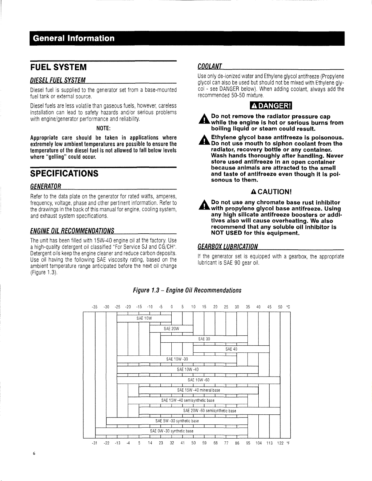
ENGINE
The
unit
a
high-quality
Detergent
Use
ambient
(Figure
voltage,
exhaust
OIL
has
oils
oil
having
temperature
1.3).
data
plateonthe
phase
and
backofthis
system
specifications.
RECOMMENDATIONS
been
filled
with
detergent
keep
the
oil
the
engine
following
range
classified
anticipated
generator
gaseous
hazards
and
NOTE:
generator
other
manual
15W-40
cleaner
SAE
viscosity
set
fromabase-mounted
fuels,
however,
and/or
serious
reliability.
are
possibletoensure
allowedtofall
for
rated
watts,
pertinent
"For
information.
for
engine,
engine
oilatthe
ServiceSJand
and
reduce
cooling
carbon
rating,
before
the
careless
problems
where
below
levels
amperes,
Refer
system,
factory.
CG/CH".
deposits.
basedonthe
next
oil
change
the
to
Use
COOLANT
Use
only
de-ionized
glycol
can
alsobeused
col-see
DANGER
recommended
50-50
water
but
below).
mixture.
and
should
When
Ethylene
notbemixed
adding
glycol
coolant,
antifreeze
with
always
~
A.
Do not remove the radiator pressure cap
....
while the engine is hot or serious burns from
boiling liquid or steam could result.
A.
Ethylene glycol base antifreeze Is poisonous.
....
Do not use mouth to siphon coolant from the
radiator, recovery bottle or any container.
Wash hands thoroughly after handling.
store used antifreeze
because animals are attracted to the smell
and taste of
antifreeze even though It is poi-
sonoustothem.
ACAUTIONI
A.
Do not use any chromate base rust Inhibitor
....
with propylene glycol base antifreeze. Using
any high silicate antifreeze boosters or additives also will cause overheating. We also
recommend that any soluble
NOT USED for this equipment.
GEARBOX
If
the
lubricantisSAE90gear
LUBBICATION
generator
setisequipped
oil.
in an open container
011
Inhibitor Is
withagearbox,
the
(Propylene
Ethylene
gly-
add
Never
appropriate
the
Figure
-35
-30
-25
-20
-31
-22 -13
6
-15
SAE
1.3
-10
lOW
SAEOW·30
14
-
Engine
·5
SAE
SAE1OW
SAE
15W
SAE5W-30
23
32
I
I
20W
I I
SAE
SAE
-40
synthetic
synthetic
41
Oil
Recommendations
15
20
SAE
30
-30
lOW
-40
SAE
10W
·60
l5W
-40
mineral
base
semisynthetic
SAE
base
20W
base
50
base
·60
semisynthetic
59
68
25
SAE
77
base
30
35
40
45
50'C
40
86
95
104
113 122
'F
Page 9
FUEL
SYSTEM
Diesel
Fuel
Emergency
Manual
(part
1.
Beginning
diesel
A.
Sulfur
B.
Cetane
2.
Beginning
diesel
A.
Sulfur
B.
Cetane
BATTERY
Whenaunitissupplied
use
the
following
mum
Cold
Diesel
6.7L
(100,
6.7L
(150,
10.3L
12.9L
13.0L
16.0L
18.0L
22.0L
Fill
the
battery
have
the
REDUIREMENTS
System:
Electric
fuel
• A
• A
fuel
• A
• A
See
Power
no.
046622).
October1,2007,
must
use
contentof500
indexoraromatic
minimum
maximum
October1,2010,
must
use
contentof15
indexoraromatic
minimum
maximum
INSTALLATION
tabletoproperly
Cranking
Engine
2.4L
3.4L
4.5L
8.7L
battery
Ampere
130Kw)1or2XGRP
175Kw)
with
the
fUlly
charged
AND
Chapter8of
Systems
diesel
cetane
aromatic
diesel
cetane
aromatic
with
Battery
GRP27or
GRP31or
2X
2x
proper
Installer's
owners
fuel
that
parts
per
contentasfollows:
indexof40
contentof35
owners
fuel
that
parts
per
contentasfollows:
indexof40
contentof35
outabatteryorduring
select
required
Size
GRP
GRP
31E
GRP
31
GRP31or
GRP
80
electrolyte
before
RECOMMENDATIONS
Engine-Generator
Guide
and
operators
meets:
million
or;
volume
and
operators
meets:
million
(ppm)
or;
volume
the
battery
foraparticular
31
31
2x
fluidifnecessary
installing
it.
Stationary
and
Reference
(ppm)
maximum.
percent.
maximum.
percent.
replacement
size
and
unit.
Minimum
650or925
925
925
925
925or1155
that
that
CCA
use
use
mini-
and
General
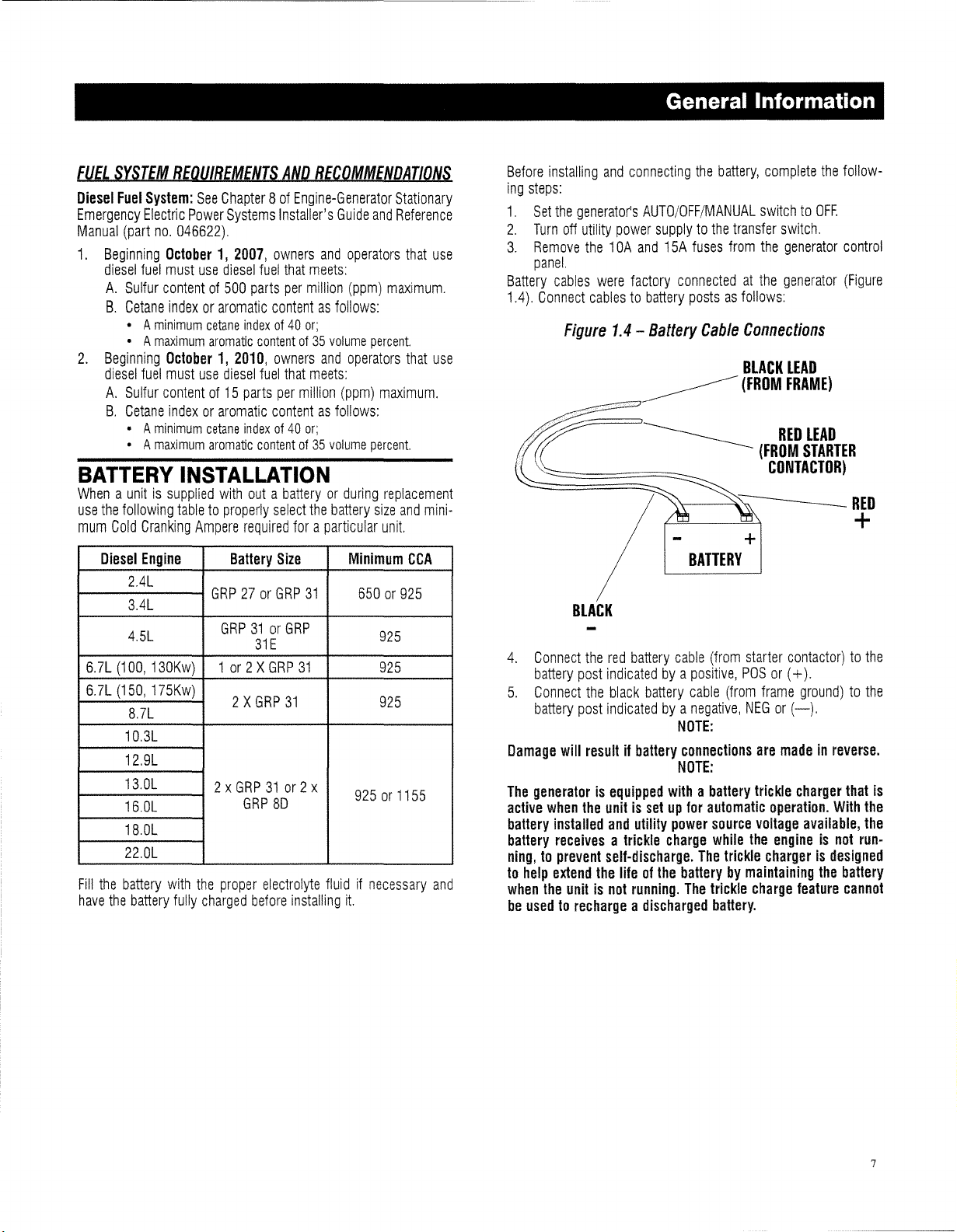
Before
installing
ing
steps:
1.
Set
the
2.
Turn
3.
Remove
panel.
Battery
cables
1.4).
Connect
4.
Connect
battery
5.
Connect
battery
Damage
The
generatorisequipped
active
when
battery
installed
battery
receivesatrickle
ning,toprevent
to
help
extend
when
the
be
usedtorechargeadischarged
and
generator's
off
utility
power
the
10A
were
cablestobattery
Figure
1.4
---<~~
BLACK
the
red
post
indicatedbya
the
black
post
indicatedbya
will
resultifbattery
the
unitissetupfor
and
self-discharge.
the
lifeofthe
unitisnot
connecting
AUTO/OFF/MANUAL
supplytothe
and
15A
factory
-
Battery
~
___________
battery
battery
withabattery
utility
charge
running.
Information
the
battery,
fuses
connectedatthe
postsasfollows:
Cable
complete
switchtoOFF.
transfer
from
switch.
the
generator
generator
Connections
BLACK
LEAD
(FROM
FRAME)
RED
(FROM
CONTACTOR)
+
BATTERY
cable
(from
starter
contactor)tothe
positive,
cable
negative,
NOTE:
connections
NOTE:
power
batterybymaintaining
The
pas
(from
automatic
source
while
The
trickle
trickle
battery.
or
(+).
frame
NEGor(-).
are
madeinreverse.
trickle
charger
operation.
voltage
the
engineisnot
chargerisdesigned
charge
feature
the
follow-
control
(Figure
LEAD
STARTER
ground)tothe
that
is
With
the
available,
the
the
run-
battery
cannot
7
Page 10
General Information
THE
BATTERY
~
A Do
tAbattery
/r\ A
illand
• Remove
• Remove
• Use
• Wear
• Do
• Disconnect
Jt..
....
A The
....
The
• Wear
•
•
•
&.
Lmbecause
• DO NOT SMOKE
• DO NOT
and
•
A Be
....
not
disposeofthe
Is
capableofexploding.
battery
precautions
ingonbatteries:
erator
tools
rubber
not
battery;
or
disconnecting
Do
electrolyte
the
harmfultothe
conductive
following
full
Where
Immediately
Where
thoroughly
seek
medical
Spilled
an
acid
Istouseasolutionof1
bicarbonateofsodato1
water. The
be
added
ing)
has
flushed
lead-acid
following
Discharge
touching
ed
metal
to
the
battery
or
MANUAL,
startassoonasthe
nected.
presentsariskofelectrical
high
short
circuit
aretobe
the
10A
and
control
lay
not
skin
electrolyteIsa
electrolyte
electrolyte
electrolyteIstobewashed
neutralizing
sure
panel.
watches,
with
toolsormetal
and
charging
openormutilate
and
eye
and
bicarbonateofsoda
until
ceased.
with
they
cause
static
the
surface.
the
OFF
cables.Ifthe
ringsorother
Insulated
gloves
battery
IA
WARNING!1
has
been
eyes,
skin
and
procedures
protection
contacts
with
water;
contacts
Immediately
attention;
the
The
water
batteries
generate
procedures
when
flameorsparkinbattery
electricity
batterybyfirst
AUTO/OFF/MANUAL
position
the
battery
current.
observed
15A
fuses
handles;
and
boots;
parts
source
terminals.
knowntobe
andtobe
dilute
and
corrosive.
aretobe
and
and
agent.Acommon
pound
gallon(4liters)
evidenceofreaction
resulting
and
the
presentariskoffire
hydrogen
aretobe
near
before
switchissettoAUTO
generator
battery
In a
fire.
The
following
when
from
the
metal
on
topofthe
priortoconnecting
the
battery.
harmful
toxic.
sulfuric
eyes.Itis
protective
the
the
with
area
the
from
touchingaground-
connecting
can
acid
electrically
observed:
skin,
washItoff
eyes,
flush
water
down
(500
grams)
solutionisto
liquidIsto
dried.
gas.
followed:
battery;
body
switchisset
crank
cables
The
shock
work-
gen-
objects;
Released
that
clothing;
and
with
practice
of
(foam-
be
The
area;
before
the
and
are
con-
to
Is
A Be
tAand
Servicingofthe
sonnel
Keep
A
on
nected
necting
GENERATOR
sure
the
utility
the
10A
and
the
generator
occuratthe
attached
knowledgeableofbatteries
unauthorized
negative
the
ground
wiring
and
terminals
the
batterytothe
battery
and
batteryistobeperformedorsupervisedbyper-
personnel
systemisused.
diagrams.
are
control
causeanexplosion.
AC
CONNECTIONS
See
"Voltage
several
wiresinthe
accordingtothe
for
the
tion,
refertoFigures
Voltage
particular
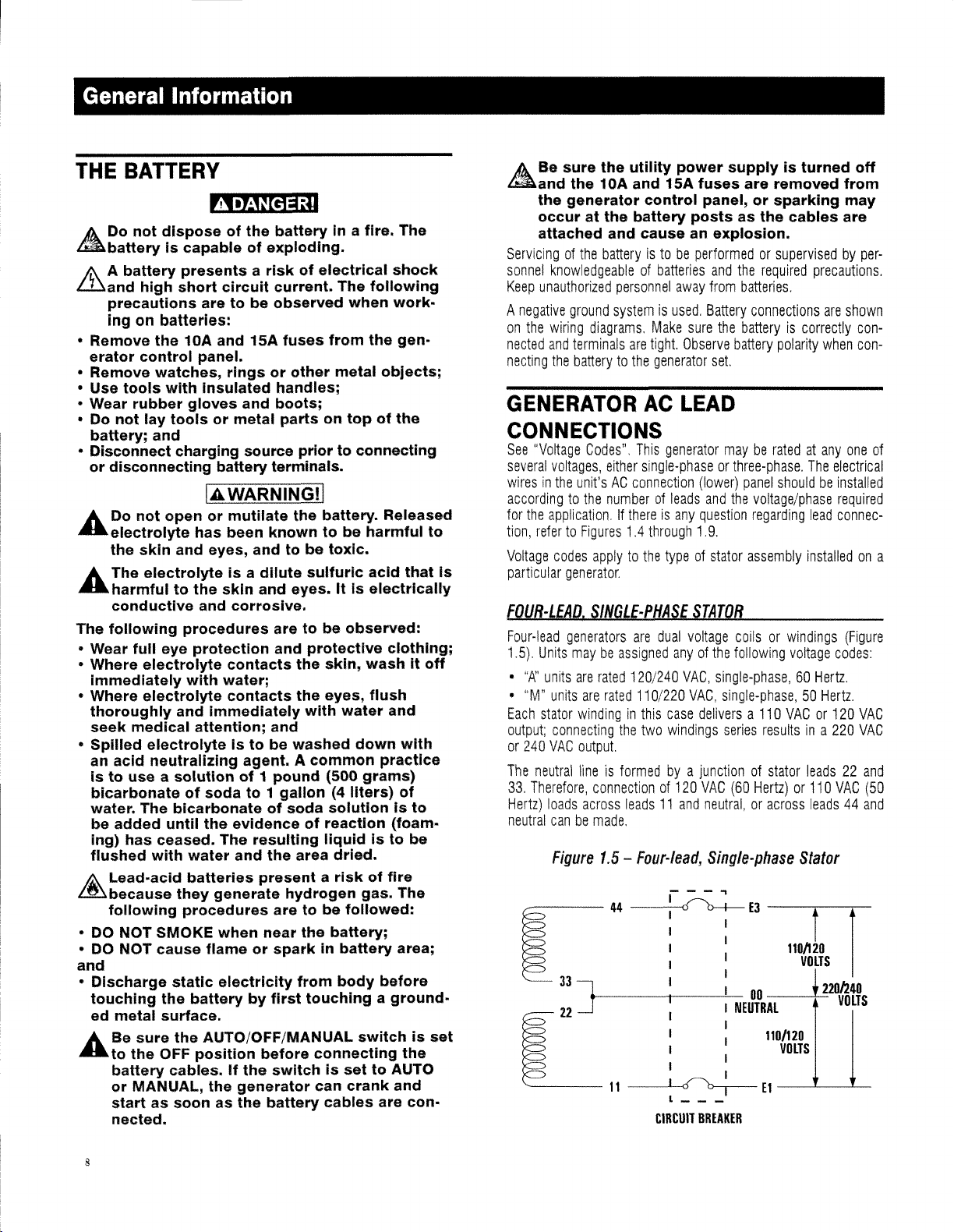
fOUR-LEAD,
Four-lead
1.5).
Units
•
"{:>:.'
•
"M"
Each
output;
or
240
The
neutral
33.
Therefore,
Hertz)
neutral
Codes".
voltages,
unit'sAGconnection
application.Ifthereisany
codes
generator
This
either
single-phaseorthree-phase.
numberofleads
1.4
through
applytothe
.
SINGLE-PHASE
generators
maybeassigned
units
are
units
are
stator
windinginthis
connecting
VAC
output.
lineisformedbya
loads
across
canbemade.
Figure
are
rated
120/240
rated
110/220
the
two
connectionof120
leads11and
1.5
-
Four-lead,
44~EJ
E
JJ ] I :
22
E
11~E1
power
15A
fuses
panel,orsparking
postsasthe
away
Make
sure
tight.
Observe
generator
LEAD
generator
(lower)
question
1.9
typeofstator
STATOR
dual
voltage
anyofthe
VAG,
VAG,
case
deliversa110
windings
junctionofstator
VAG
neutral,oracross
I I
I
I
I I
I
I :
I
I I
l _
CIRCUIT
BREAKER
supplyisturned
are
removed
cables
and
the
required
from
batteries.
Battery
connections
the
batteryiscorrectly
battery
set.
mayberatedatanyone
panel
and
the
voltage/phase
regarding
.
assembly
coilsorwindings
following
single-phase,60Hertz.
single-phase,50Hertz.
series
resultsina
(60
Hertz)or110
Single-phase
II
00
NEUTRAL:lloLTS
110/120
I
precautions.
polarity
when
The
shouldbeinstalled
lead
installedona
voltage
VAGor120
leads22and
leads44and
Stator
110/120
VOLTS
b20h40
VOLTS
off
from
may
are
are
shown
concon-
electrical
required
connec-
(Figure
codes:
220
VAC
of
VAG
VAG
(50
8
Page 11
General Information
Figure
240V
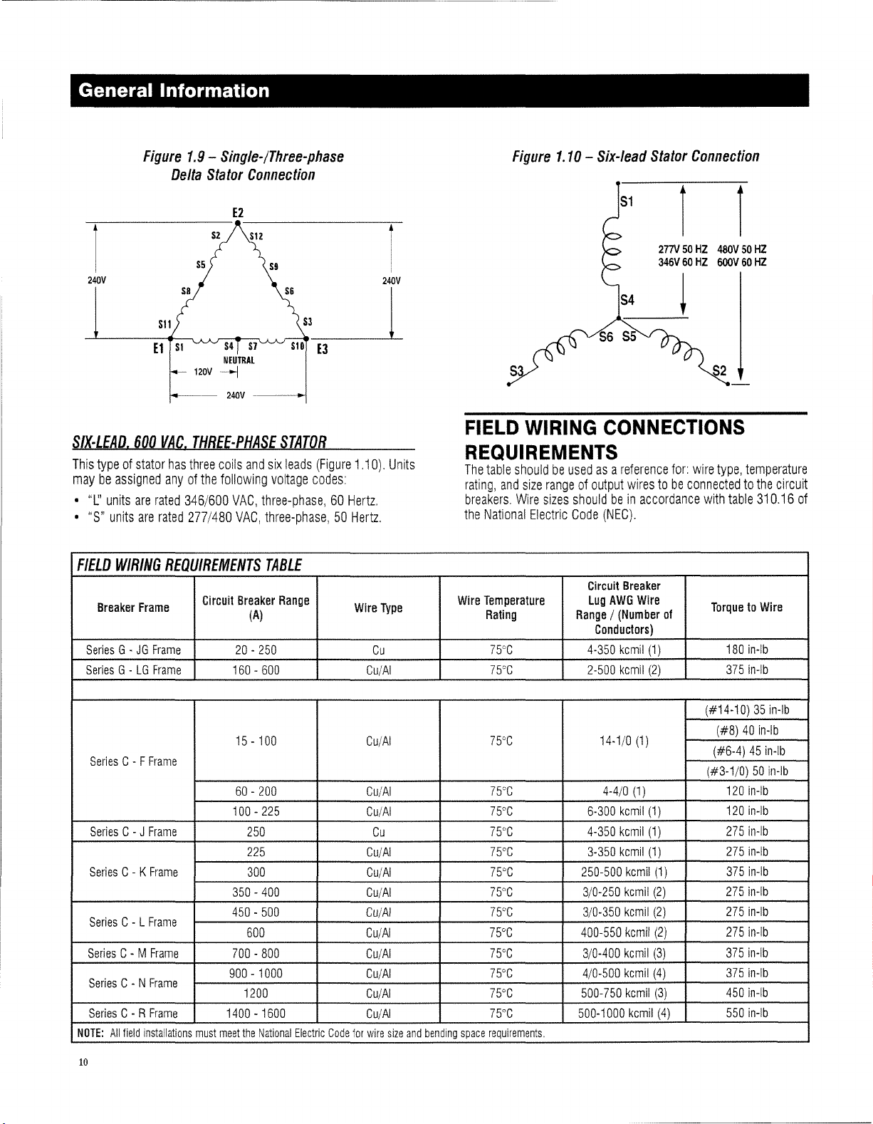
SIX-LEAD.
This
maybeassigned
•
"1.:'
•
"5"
FIELD
SeriesG-JG
SeriesG-LG
600
typeofstator
units
are
units
are
WIRING
Breaker
Frame
1.9
-
Single-/Three-phase
Delta
Stator
Connection
E2
SII
--
VAG,
has
anyofthe
rated
346/600
rated
240V
----J
THREE-PHASE
three
coils
and
following
VAG,
277/480
VAG,
REQUIREMENTS
Gircuit
Breaker
(A)
Frame
Frame
20-250
160-600
S6
S3~
STATOR
six
leads
(Figure
1.10).
voltage
codes:
three-phase,60Hertz.
three-phase,50Hertz.
TABLE
Range
Wire
Cu/AI
Cu
240V
I
Units
Type
Figure
FIELD
1.10-Six-lead
WIRING
REQUIREMENTS
The
table
shouldbeusedasa
rating,
and
size
rangeofoutput
breakers.
the
Wire
Wire
sizes
National
Temperature
Rating
Electric
75cC
75CC
shouldbein
Gode
Circuit
Lug
Range/(Number
4-350
2-500
Stator
Connection
51
1 1
277V
50HZ
346V60HZ
480V50HZ
600V60HZ
!
S2
CONNECTIONS
reference
wirestobe
(NEG).
Breaker
AWG
Gonductors)
kemil
kemil
for:
connectedtothe
accordance
Wire
of
(1)
(2)
wire
type,
with
TorquetoWire
temperature
table
310.16
180
in-Ib
3751n-lb
circuit
of
Series
Series
Series
Series
Series
Series
Series
NOTE:
10
All
C- F
C-J
C- K
C- L
C- M
C- N
C- R
field
Frame
Frame
Frame
Frame
Frame
Frame
Frame
installations
must
15-100
60-200
100-225
250
225
300
350-400
450-500
600
700-800
900-1000
1200
1400-1600
meet
the
National
Electric
Code
for
Cu/AI
CulAl
Cu/AI
Cu
CulAl
CulAl
Cu/AI
Cu/AI
Cu/AI
Cu/AI
Cu/AI
Cu/AI
Cu/AI
wire
size
and
bending
75cC
75cC
75°C
75°C
75°C
75DC
75DC
75°C
75°C
WC
75°C
WC
75°C
space
requirements.
14-1/0
4-4/0
6-300
4-350
3-350
250-500
3/0-250
3/0-350
400-550
3/0-400
4/0-500
500-750
500-1000
(1)
kemll
kemll
kemll
kemll
kemil
kemil
kemll
kemll
kemll
kemil
kemil
(1)
(1)
(1)
(1)
(2)
(2)
(2)
(3)
(4)
(3)
(1)
(4)
(#14-10)35In-Ib
(#8)40In-Ib
(#6-4)45in-Ib
(#3-1/0)50in-Ib
120
in-Ib
120
in-Ib
275
in-Ib
275
in-Ib
375
In-Ib
2751n-lb
275
in-Ib
275
in-Ib
3751n-lb
375
In-Ib
450
In-Ib
550
in-Ib
Page 12

General
Information
FIELD
WIRING
500Kw
with
2500A
connectionofthe
shouldbefollowedinordertoobtainasuitable
tiontothe
Volvo
Series
have
•
Conductor
accept
aluminum
•
Suggested
•
Manufacturers
•
Type
-
•
Wire
Size
Required
Belowisthe
to
the
Buss
•
M12x65mm
Washers,
CONNECTIONSTOBUSS
and
500/600Kw
C- R
Frame
Breakers
Buss
Bars
suppliedinthe
Field
Conductors.
Buss
Bars.
Lugs
-
The
Buss
Aluminum
stranded
Dual
-
Compression
wire
.
Manufacturer
Part
No.
-
Rated
(Al/CU),
600
kcmil
-
BLUA060D2
Hardware
recommended
Bars,
Grade
Lock
Washer
hardware
8,8
and
Doosan
Bars
PENN
Two
Hex
Nut
BARS
powered
rated
1400,
connection
The
following
have
Lugs
suitable
UNION
CORP
Studs
requiredtoattach
Head
Cap
or
•
1/2"-20x2.5"
Washers,
Required
M12
1/2"
Torque
Lock
Grade
SAE5Hex
Washer
-
Tighten
Dry75Ft-Lbs
Dry85FHbs
and
Nut
fasteners
Head
to:
Cap
units
supplied
1600,
2000
Module
for
information
electrical
been
spaced13/4"
Screw,
Screw,
Lubed58FHbs
Lubed65FHbs
connec-
configured
for
copper
the
M12
and
the
to
or
Apart
Lugs
Flat
Flat
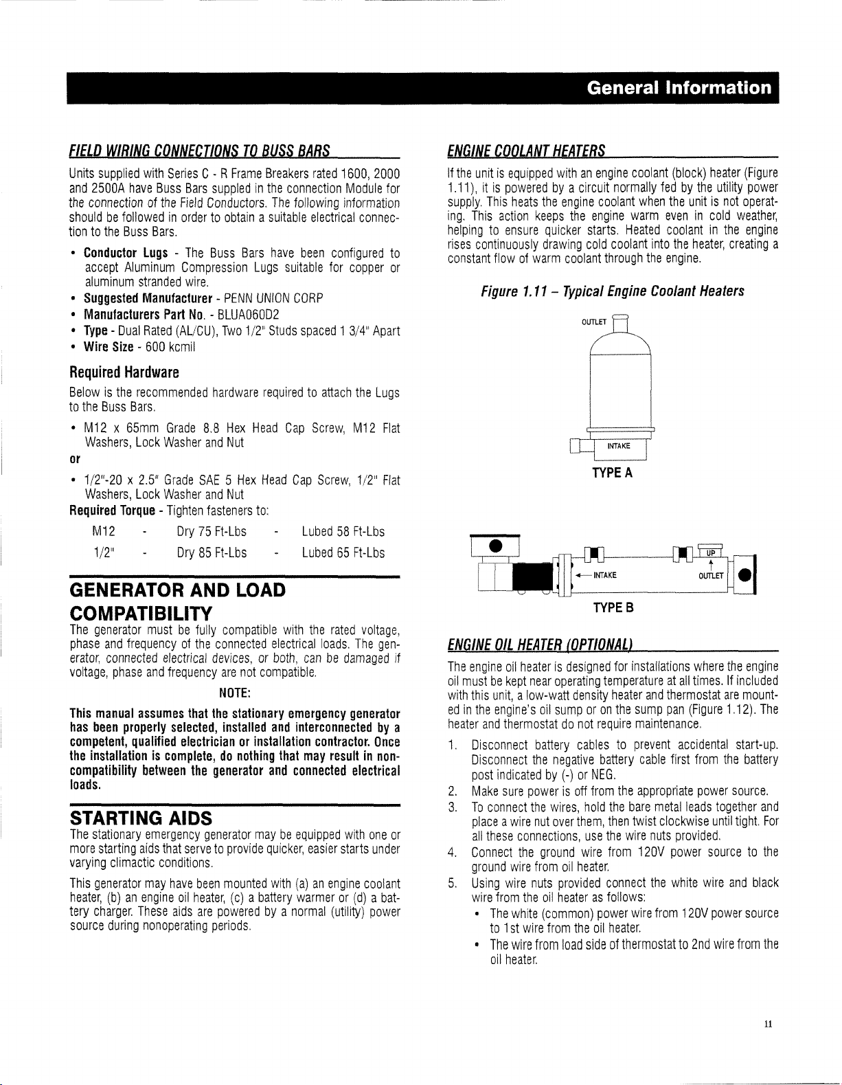
ENGINE
If
1.11),itis
supply.
ing,
helpingtoensure
rises
constant
COOLANT
the
unitisequipped
poweredbya
This
heats
This
action
continuously
flowofwarm
Figure
1.11-
HEATERS
withanengine
circuit
the
engine
keeps
the
quicker
drawing
coolant
Typical
OUTLET
coolant
engine
starts,
cold
through
TYPE
coolant
normally
when
warm
Heated
coolant
Engine
A
(block)
fedbythe
the
evenincold
coolantinthe
into
the
the
engine
Coolant
heater
utility
unitisnot
heater,
creating
.
Heaters
(Figure
power
operat-
weather,
engine
a
GENERATOR
AND
COMPATIBILITY
The
generator
phase
and
erator,
connected
voltage,
This
manual
has
been
competent,
the
installationiscomplete,donothing
compatibility
loads.
STARTING
The
stationary
more
starting
varying
This
generator
heater,
tery
charger.
source
mustbefully
frequencyofthe
electrical
phase
and
assumes
properly
qualified
between
emergency
aids
that
climactic
(b)anengine
during
conditions.
may
These
nonoperating
compatible
connected
devices,orboth,
frequency
are
NOTE:
that
the
selected,
installed
electricianorinstallation
the
generator
AIDS
generator
servetoprovide
have
been
mounted
oil
heater,
aids
are
poweredbya
periods.
LOAD
with
electrical
not
compatible,
stationary
(c)abattery
emergency
and
that
and
maybeequipped
quicker,
with
the
rated
voltage,
loads.
The
gen-
canbedamaged
generator
interconnectedbya
contractor.
may
resultinnon-
connected
easier
(a)anengine
warmeror(d)abat-
normal
(utility)
Once
electrical
with
one
starts
under
coolant
power
or
TYPES
ENGINE
if
The
oil
with
edinthe
heater
1.
2.
3.
4.
5.
OIL
HEATER
engine
oil
heaterisdesigned
mustbekept
this
and
Disconnect
Disconnect
post
Make
To
connect
placeawire
all
these
Connect
ground
Using
wire
•
•
near
unit,alow-watt
engine's
indicatedby(-)orNEG,
from
The
to1st
The
oil
oil
thermostatdonot
battery
the
sure
powerisoff
the
nut
connections,
the
ground
wire
from
wire
nuts
the
oil
white
(common)
wire
wire
from
heater.
(OPTIONAL)
for
operating
sumporon
negative
wires,
over
provided
heaterasfollows:
from
temperatureatall
density
heater
the
require
cablestoprevent
battery
from
the
hold
the
them,
then
use
the
wire
from
oil
heater,
connect
power
the
oil
heater.
load
sideofthermostatto2nd
installations
and
thermostat
sump
pan
maintenance.
accidental
cable
first
appropriate
bare
metal
twist
clockwise
wire
nuts
provided.
120V
power
the
white
wire
from
where
the
engine
times.Ifincluded
are
mount-
(Figure
1.12).
start-up.
from
the
battery
power
source.
leads
together
until
tight.
sourcetothe
wire
and
120V
power
source
wire
from
The
and
For
black
the
11
Page 13
-------_.
__
_--_
..
_-------
FIELD
WIRING
Units
supplied
and
2500A
the
connectionofthe
shouldbefollowedinordertoobtainasuitable
tiontothe
•
Conductor
accept
aluminum
•
Suggested
•
Manufacturers
•
Type
-
•
Wire
Size
Required
Belowisthe
to
the
Buss
•
M12x65mm
Washers,
or
•
1/2"-20x2.5"
Washers,
Required
M12
1/2"
CONNECTIONSTOBUSS
with
Series
C- R
have
Buss
Bars
suppledinthe
Field
Conductors.
Buss
Bars.
lugs
-
The
Buss
Aluminum
stranded
Dual
-
Compression
wire.
Manufacturer
Part
No.
-
Rated
(AL/CU),
600
kcmil
-
BLUA060D2
Hardware
recommended
Bars.
Grade
Lock
Washer
Grade
Lock
Washer
Torque
-
Tighten
hardware
8.8
and
SAE5Hex
and
fasteners
Dry75Ft-Lbs
Dry85Ft-Lbs
Frame
Bars
PENN
Two
Hex
Nut
Nut
BARS
Breakers
connection
The
following
have
Lugs
suitable
UNION
CORP
1/2"
Studs
requiredtoattach
Head
Cap
Head
Cap
to:
rated
1600,
2000
Module
information
electrical
been
spaced13/4"
Screw,
Screw,
Lubed58Ft-Lbs
Lubed65Ft-Lbs
connec-
configured
for
copper
Apart
the
Lugs
M12
1/2"
for
to
or
Flat
Flat
ENGINE
If
1.11),itis
supply.
ing.
helpingtoensure
rises
constant
COOLANT
the
unitisequipped
poweredbya
This
heats
This
action
continuously
flowofwarm
Figure
1.11-
HEATERS
withanengine
circuit
the
engine
keeps
the
quicker
drawing
coolant
Typical
OUTLET
General
coolant
normally
coolant
when
engine
warm
starts.
Heated
cold
coolant
through
TYPE
the
Engine
A
Information
(block)
heater
fedbythe
the
evenincold
coolantinthe
into
the
engine.
Coolanl
utility
unitisnot
heater,
Healers
(Figure
power
operat-
weather,
engine
creating
a
GENERATOR
AND
COMPATIBILITY
The
generator
phase
and
erator,
connected
voltage,
This
manual
has
been
competent,
the
installationiscomplete,donothing
compatibility
loads.
STARTING
The
stationary
more
starting
varying
This
generator
heater,
tery
charger.
source
mustbefully
frequencyofthe
electrical
phase
and
frequency
assumes
properly
qualified
between
emergency
aids
that
climactic
(b)anengine
during
conditions.
may
These
nonoperating
compatible
connected
devices,orboth,
are
NOTE:
that
the
selected,
electricianorinstallation
the
generator
installed
AIDS
generator
servetoprovide
have
been
mounted
oil
heater,
(c)abattery
aids
are
poweredbya
periods.
LOAD
with
electrical
not
compatible.
stationary
emergency
and
that
and
maybeequipped
quicker,
with
normal
the
rated
voltage,
loads.
The
gen-
canbedamaged
generator
interconnectedbya
contractor.
may
resultinnon-
connected
easier
(a)anengine
warmeror(d)abat-
(utility)
electrical
with
one
starts
under
coolant
power
Once
or
1~'_KE
if
The
oil
with
edinthe
heater
1.
2.
3.
4.
5.
ENGINE
OIL
HEATER
engine
oil
heaterisdesigned
mustbekept
this
and
Disconnect
Disconnect
post
Make
To
connect
placeawire
all
these
Connect
ground
Using
wire
•
•
near
unit,alow-watt
engine's
indicatedby(-)orNEG.
from
The
to1st
The
oil
oil
thermostatdonot
battery
the
sure
powerisoff
the
nut
connections,
the
ground
wire
from
wire
nuts
the
white
(common)
wire
wire
from
heater.
(OPTIONALl
operating
density
sumporon
cablestoprevent
negative
wires,
over
them,
oil
heater.
provided
oil
heaterasfollows:
from
the
load
__
TYPEB
for
temperatureatall
heater
the
require
battery
from
the
hold
the
bare
then
use
the
wire
wire
from
connect
power
wire
oil
heater.
sideofthermostatto2nd
~
installations
and
thermostat
sump
pan
(Figure
maintenance.
accidental
cable
first
appropriate
metal
leads
twist
clockwise
nuts
provided.
120V
power
the
white
from
120V
where
the
engine
times.Ifincluded
are
mount-
1.12).
The
start-up.
from
the
battery
power
source.
together
until
sourcetothe
wire
power
wire
tight.
and
from
and
For
black
source
the
11
Page 14
General Information
A.
Be
surenobare wire or wire strands are vis-
~Ible
6.
Push
all
7.
Assemble
8.
Reconnect
tive
cable
ACAUTIONI
after making connections.
wires
and
wire
nuts
into
junction
junction
firsttothe
box
battery
cablestobattery
Figure
covertojunction
battery
post
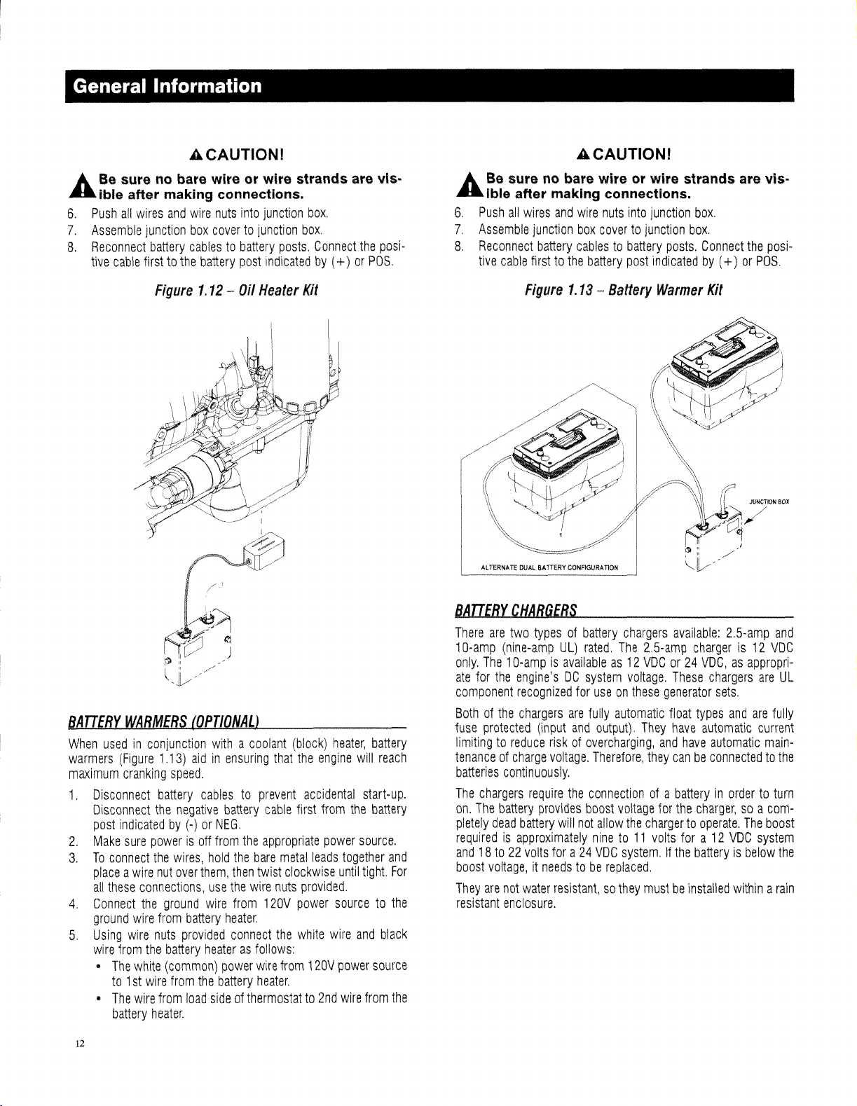
1.12
-
Oil
Heater
posts.
indicated
box.
box
Connect
by
Kit
(+)
the
or
posi-
POS.
ACAUTIONI
A.
Be
surenobare wire or wire strands are vis-
~
Ible after making connections.
6.
Push
all
wires
and
wire
nuts
7.
Assemble
8,
Reconnect
tive
cable
junction
battery
firsttothe
Figure
box
covertojunction
cablestobattery
battery
1.13
-
Battery
into
post
junction
posts,
indicated
Warmer
box,
box,
Connect
by
Kit
(+)
or
the
posi-
POS,
BATTERY
When
warmers
maximum
1,
2.
3,
4,
5,
WARMERS
usedinconjunction
(Figure
cranking
Disconnect
Disconnect
post
indicatedby(-)orNEG,
Make
sure
To
connect
placeawire
all
these
Connect
ground
Using
wire
wire
from
•
The
to1st
•
The
battery
1.13)
speed.
battery
the
negative
powerisoff
the
wires,
nut
over
connections,
the
ground
wire
from
battery
nuts
provided
the
battery
white
(common)
wire
from
wire
from
load
heater,
(OPTIONAL)
withacoolant
aidinensuring
cablestoprevent
battery
from
hold
them,
use
the
wire
heater.
connect
heaterasfollows:
power
the
battery
sideofthermostatto2nd
the
the
then
from
bare
wire
wire
heater,
that
cable
appropriate
metal
twist
clockwise
nuts
120V
the
from
(block)
the
engine
accidental
first
from
power
leads
provided.
power
white
120V
heater,
battery
will
reach
start-up.
the
battery
source,
together
until
tight.
sourcetothe
wire
and
black
power
source
wire
from
and
For
the
BATTERY
There
10-amp
only.
ate
component
Bothofthe
fuse
limitingtoreduce
tenanceofcharge
batteries
The
on,
pletely
requiredisapproximately
and18to22volts
boost
They
resistant
CHARGERS
are
two
typesofbattery
(nine-amp
The1Q-ampisavailableas12
for
the
engine'sDCsystem
recognized
protected
continuously,
chargers
The
battery
dead
voltage,itneedstobe
are
not
enclosure.
UL)
rated,
for
chargers
battery
water
are
(input
and
riskofovercharging,
voltage.
require
the
provides
will
not
fora24
resistant,sothey
chargers
The
2,5-amp
VDCor24
voltage,
useonthese
fully
automatic
output),
Therefore,
connectionofa
boost
allow
nineto11
VDC
They
they
voltage
the
chargertooperate.
volts
system,Ifthe
replaced.
mustbeinstalled
available:
These
generator
float
have
and
have
canbeconnectedtothe
batteryinordertoturn
for
the
fora12
2,5-amp
chargeris12
VDC,asappropri-
chargers
sets.
types
and
are
automatic
automatic
charger,soa
The
VDC
batteryisbelow
withinarain
and
VDC
are
UL
fully
current
main-
com-
boost
system
the
12
Page 15
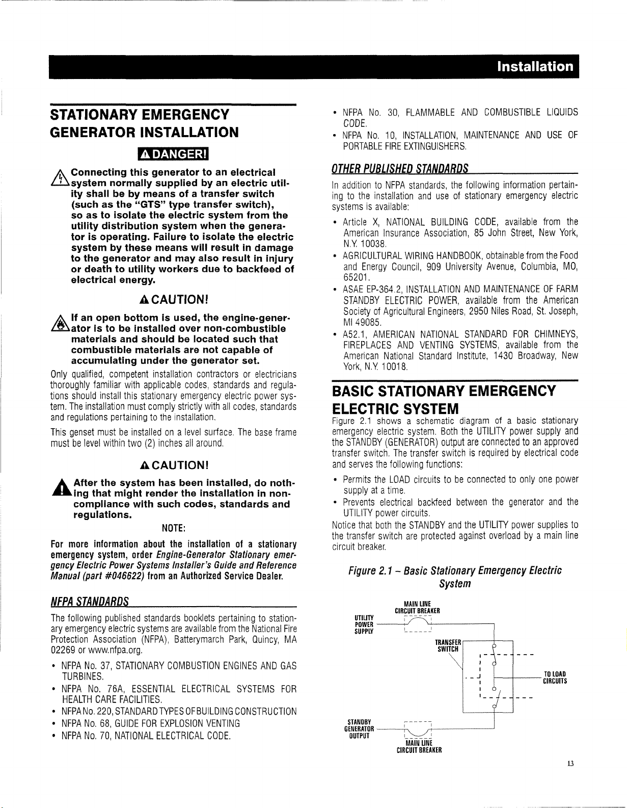
STATIONARY
GENERATOR
EMERGENCY
INSTALLATION
~
k..
Connecting this generator to an electrical
illsystem
ity shall
(such as the "GTS" type transfer switch),
so as to isolate the electric system from the
utility distribution system when the generator is operating. Failure to isolate the electric
system by these means will result in damage
to the generator and may also result in injury
or death to utility workers due to backfeed of
electrical energy.
t
If
Lmator
materials and should be located such that
combustible materials are not capable of
accumulating under the generator set.
Only
qualified,
thoroughly
tions
should
tem.
The
and
regulations
This
genset
mustbelevel
A After the system has been installed, do noth-
.....
ing that might render the installation in non·
compliance with such codes, standards and
regulations.
For
more
emergency
gency
Electric
Manual
normally supplied by an electric util-
be
by means of a transfer switch
ACAUTIONI
an open bottom is used, the engine-gener-
is to be installed over non-combustible
competent
familiar
install
installation
pertainingtothe
mustbeinstalledona
within
with
this
must
two
installation
applicable
stationary
comply
(2)
inches
contractorsorelectricians
codes,
standards
emergency
strictly
with
electric
all
codes,
installation.
level
all
around.
surface.
The
and
regula-
power
standards
base
ACAUTIONI
NOTE:
information
system,
Power
(part
#046622)
about
the
installationofa
order
Engine-Generator
Systems
Installer's
fromanAuthorized
Stationary
Guide
Service
and
Reference
Dealer.
stationary
emer-
sys-
frame
•
NFPA
No.
30,
CODE.
•
NFPA
No.
10,
INSTALLATION,
PORTABLE
OTHER
In
additiontoNFPA
ingtothe
FIRE
EXTINGUISHERS.
PUBLISHED
installation
systemsisavailable:
•
ArticleX,NATIONAL
American
NY
o
AGRICULTURAL
and
10038,
Energy
Insurance
Council,
65201.
•
ASAE
EP-364.2,
STANDBY
ELECTRIC
SocietyofAgricultural
M149085.
•
A52.1,
AMERICAN
FIREPLACES
American
York,
N.Y
BASIC
ELECTRIC
Figure
2.1
emergency
the
STANDBY
transfer
and
o
o
Notice
the
circuit
switch.
serves
Permits
supplyata
Prevents
UTILITY
that
transfer
breaker.
Figure
AND
National
10018.
STATIONARY
SYSTEM
showsaschematic
electric
(GENERATOR)
The
the
following
the
LOAD
time
.
electrical
power
circuits.
both
the
switch
2.1
-
Basic
FLAMMABLE
AND
STANDARDS
standards,
and
WIRING
INSTALLATION
VENTING
Standard
system.
transfer
circuitstobe
backfeed
STANDBY
are
the
useofstationary
BUILDING
Association,85John
HANDBOOK,
909
University
POWER,
Engineers,
NATIONAL
SYSTEMS,
Institute,
diagramofa
Both
the
output
switchisrequiredbyelectrical
functions:
between
and
protected
against
Stationary
System
Installation
COMBUSTIBLE
MAINTENANCE
following
AND
information
emergency
CODE,
available
Street,
New
obtainable
Avenue,
AND
MAINTENANCEOFFARM
available
2950
Niles
STANDARD
from
Road,
FOR
from
Columbia,
the
St.
CHIMNEYS,
available
1430
Broadway,
EMERGENCY
basic
UTILITY
are
connectedtoonly
the
Emergency
power
connectedtoan
the
generator
UTILITY
power
overloadbya
Electric
supply
one
supplies
LIQUIDS
USE
OF
pertain-
electric
from
the
York,
the
Food
MO,
American
Joseph,
from
the
New
stationary
and
approved
code
power
and
the
to
main
line
NFPA
STANDARDS
The
following
ary
emergency
Protection
published
electric
Association
systems
02269orwww.nfpa.org.
o
NFPA
No.
37,
STATIONARY
TURBINES.
o
NFPA
No.
76A,
ESSENTIAL
HEALTH
o
NFPA
o
NFPA
o
NFPA
No.
No.
No.
CARE
FACILITIES.
220,
STANDARD
68,
GUIDE
70,
NATIONAL
standards
(NFPA),
booklets
are
available
Batterymarch
COMBUSTION
ELECTRICAL
TYPESOFBUILDING
FOR
EXPLOSION
ELECTRICAL
pertainingtostationfrom
the
National
Park,
Quincy,
ENGINES
AND
SYSTEMS
CONSTRUCTION
VENTING
CODE.
Fire
MA
GAS
FOR
UTIUTY
POWER
--t-/
SUPPLY
STANDBY
GENERATOR
OUTPUT
--~'
MAIN
CIRCUIT
'- - - -
--,
MAIN
CIRCUIT
UNE
BREAKER
--
TRANSFER
SWITCH
-,..;.-'
~
UNE
BREAKER
r---+-~
I-
I
,
. _ J
c--f---CIRCUITS
,
,
'-
-
--1
TO
LOAD
13
Page 16
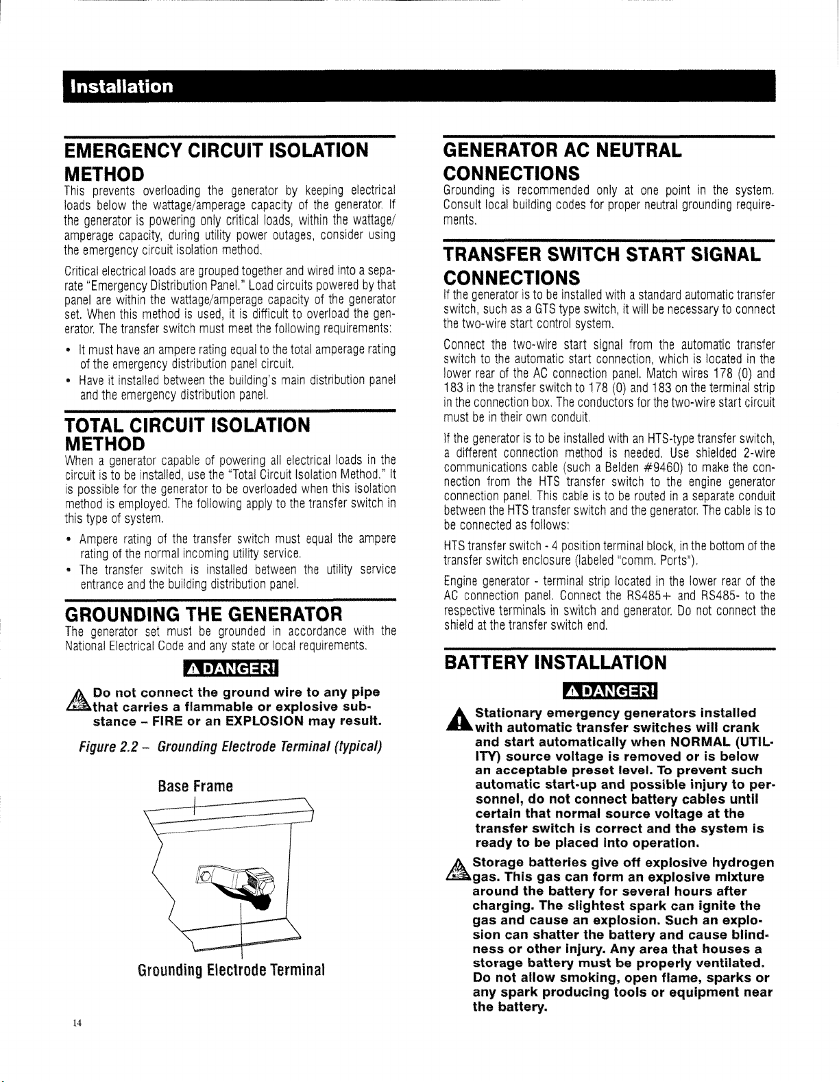
Installation
EMERGENCY
CIRCUIT
ISOLATION
METHOD
This
prevents
loads
below
the
generatorispowering
amperage
the
emergency
Critical
rate
"Emergency
panel
are
set.
When
erator,
The
•Itmust
of
the
•
Haveitinstalled
and
the
TOTAL
overloading
the
wattage/amperage
capacity,
circuit
electrical
loads
Distribution
within
the
this
methodisused,itis
transfer
haveanampere
emergency
emergency
CIRCUIT
the
generatorbykeeping
only
critical
during
utility
power
isolation
wattage/amperage
switch
distribution
between
method,
are
grouped
Panel."
must
meet
rating
the
building's
distribution
together
Load
equaltothe
panel
panel.
ISOLATION
capacityofthe
loads,
outages,
and
circuits
capacityofthe
difficulttooverload
the
total
circuit.
main
generator,
within
the
consider
wired
intoasepa-
poweredbythat
requirements:
amperage
distribution
electrical
generator
METHOD
Whenagenerator
circuitistobeinstalled,
is
possible
methodisemployed,
this
typeofsystem,
•
Ampere
ratingofthe
•
The
transfer
entrance
GROUNDING
The
generator
National
~that
Electrical
A Do not connect the ground wire to any pipe
stance - FIRE or an EXPLOSION may result.
Figure
2.2 -
14
capableofpowering
for
the
generatortobe
The
ratingofthe
normal
incoming
switchisinstalled
and
the
building
THE
set
mustbegroundedinaccordance
Code
use
the
"Total
following
transfer
distribution
GENERATOR
and
any
all
electrical
Circuit
overloaded
applytothe
switch
must
utility
service,
between
panel.
stateorlocal
loadsinthe
Isolation
Method,"
when
this
transfer
the
requirements,
switch
the
utility
~
carries a flammable or explosive sub-
Grounding
Base
Grounding
Electrode
Frame
Electrode
Terminal
Terminal
(typical)
wattage/
using
the
gen-
rating
panel
isolation
in
ampere
service
with
the
GENERATOR
AC
NEUTRAL
CONNECTIONS
Groundingisrecommended
If
Consult
ments,
TRANSFER
local
building
codes
SWITCH
onlyatone
for
proper
START
pointinthe
neutral
grounding
SIGNAL
system,
require-
CONNECTIONS
If
the
generatoristobeinstalled
switch,
suchasa
the
two-wire
Connect
switchtothe
lower
183Inthe
In
mustbein
If
a
It
communications
nection
connection
between
be
HTS
transfer
Engine
AC
respective
shieldatthe
the
rearoftheACconnection
the
connection
the
generatoristobeinstalled
different
from
the
connectedasfollows:
transfer
switch
generator-terminal
connection
BATTERY
GTS
type
start
control
two-wire
automatic
transfer
their
connection
the
panel.
HTS
switch-4position
enclosure
terminalsinswitch
transfer
start
SWitchto178
box,
The
own
conduit.
cable
(suchaBelden
HTS
This
cableistoberoutedina
transfer
panel.
Connect
switch
INSTALLATION
~
A Stationary emergency generators installed
....
with automatic transfer switches will crank
and start
ITY)
acceptable preset level.Toprevent such
an
automatic start-up and possible injury to personnel, do not connect battery cables until
certain that normal source voltage at the
transfer switch is
ready
A Storage batteries give off explosive hydrogen
~gas.
around the battery for several hours after
charging. The slightest spark
gas and cause an explosion. Such an explosion
ness
storage battery mustbeproperly ventilated.
Do not allow smoking, open flame, sparks or
any spark producing tools or equipment near
the battery.
automatically when NORMAL (UTIL-
source voltage is removed or is below
to be placed Into operation.
This gas can form an explosive mixture
can shatter the battery and cause blind-
or
other injury. Any area that houses a
withastandard
switch,itwillbenecessarytoconnect
system,
signal
from
start
connection,
panel.
(0)
and
conductors
methodisneeded,
transfer
switch
(labeled
strip
end.
for
withanHTS-type
switchtothe
and
the
terminal
"comm,
locatedinthe
the
RS485+
and
generator.Donot
correct and the system Is
automatic
the
automatic
whichislocatedinthe
Match
wires
178
183onthe
the
#9460)tomake
generator,
block,inthe
Ports"),
terminal
two-wire
Use
can ignite the
start
transfer
shielded
engine
separate
The
bottomofthe
lower
and
RS485-tothe
connect
the
generator
cableisto
rearofthe
transfer
transfer
(0)
and
strip
circuit
switch
2-wir~
con-
conduit
the
Page 17
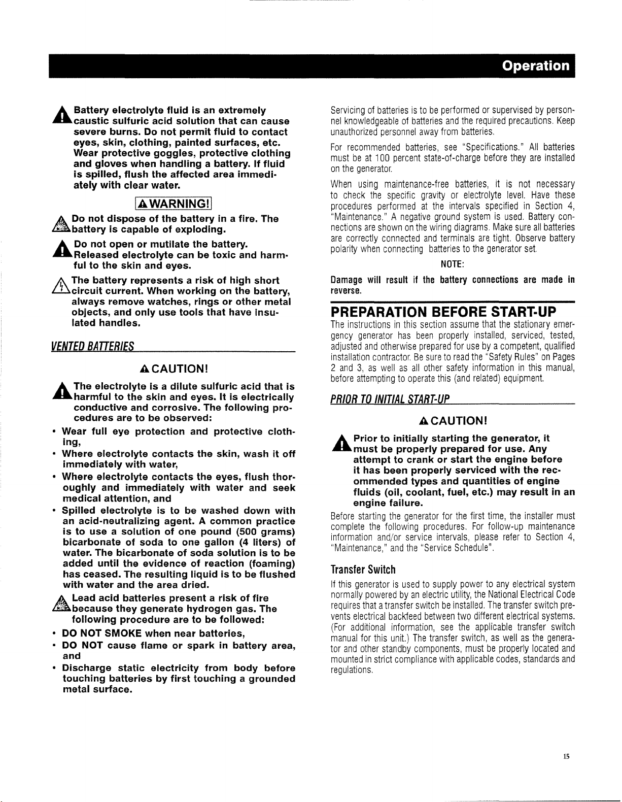
Operation
A Battery electrolyte fluid is an extremely
....
caustic sulfuric acid solution that can cause
severe burns. Do not permit fluid to contact
eyes, skin, clothing, painted surfaces, etc.
Wear protective goggles, protective clothing
and gloves when handling a battery. If fluid
is spilled, flush the affected area immediately with clear water.
IAWARNINGII
A Do not dispose of the battery in a fire. The
~battery
is capable of exploding.
A Do not open or mutilate the battery.
....
Released electrolyte can be toxic and harmful to the skin and eyes.
Ir\
The battery represents a risk of high short
illcircuit
always remove watches, rings or other metal
objects, and only use tools that have insu-
lated handles.
VENTED
current. When working on the battery,
BATTERIES
ACAUTIONI
A The electrolyte is a dilute sulfuric acid that is
....
harmful to the skin and eyes. It is electrically
conductive and corrosive. The following pro-
cedures are to be observed:
o Wear full eye protection and protective cloth-
ing,
o Where electrolyte contacts the skin, wash it off
immediately with water,
o Where electrolyte contacts the eyes, flush thor-
oughly and immediately with
medical attention, and
o Spilled electrolyte is to be washed down with
an acid-neutralizing agent. A common practice
is
to use a solution of one pound (500 grams)
bicarbonate of soda to one gallon (4 liters) of
water. The bicarbonate of soda solution is to be
added until the evidence of reaction (foaming)
has ceased. The resulting liquid is to be flushed
with
water
and the area dried.
water
and
seek
A Lead acid batteries present a risk of fire
~because
following procedure are to be followed:
o DO NOT SMOKE when
o DO
NOT
and
o Discharge static electricity from body before
touching batteries by first touching a grounded
metal surface.
they generate hydrogen gas. The
near
batteries,
cause flame or spark in battery area,
Servicingofbatteriesistobeperformedorsupervisedbypersonnel
knowledgeableofbatteries
unauthorized
For
recommended
mustbeat100
on
the
When
to
check
procedures
personnel
percent
generator.
using
maintenance-free
the
specific
performedatthe
batteries,
"Maintenance,"Anegative
nections
are
polarity
Damage
are
correctly
when
will
shownonthe
connected
connecting
resultifthe
and
the
required
away
from
batteries.
see
"Specifications,"
state-of
-charge
before
batteries,itis
gravityorelectrolyte
intervals
ground
wiring
diagrams,
and
terminals
batteriestothe
NOTE:
battery
specifiedinSection
systemisused.
Make
are
tight.
generator
connections
precautions,
All
batteries
they
are
installed
not
necessary
level.
Have
Battery
sure
all
batteries
Observe
set.
are
made
Keep
these
4,
con-
battery
in
reverse.
PREPARATION
The
instructionsinthis
gency
generator
adjusted
and
installation
2
and3,as
before
attemptingtooperate
PRIORTOINITIAL
has
otherwise
contractor.Besuretoread
wellasall
BEFORE
section
assume
been
properly
prepared
START-UP
other
this
for
safety
(and
START-UP
that
the
stationary
installed,
usebya
the"
informationinthis
related)
serviced,
competent,
Safety
Rules"onPages
equipment.
emer-
tested,
qualified
manual,
ACAUTIONI
A Prior to initially starting the generator, it
....
must be properly prepared for use. Any
attempt to crank or start the engine before
it has been properly serviced with the recommended types and quantities of engine
fluids (oil, coolant, fuel, etc.)
engine failure.
Before
starting
complete
information
"Maintenance,"
Transfer
If
this
generatorisusedtosupply
normally
requires
vents
electrical
(For
additional
manual
tor
and
mountedinstrict
the
generator
the
following
and/or
and
Switch
poweredbyan
thatatransfer
backfeed
information,
for
this
unit.)
other
standby
compliance
procedures.
service
the
intervals,
"Service
electric
switchbeinstalled,
between
The
transfer
components,
with
regulations,
for
the
Schedule",
powertoany
utility,
two
see
the
switch,aswellasthe
mustbeproperly
applicable
may
first
time,
For
follow-up
please
the
National
The
different
applicable
codes,
result in an
the
installer
must
maintenance
refertoSection
electrical
transfer
electrical
transfer
system
Electrical
switch
systems.
Code
switch
genera-
located
standards
4,
pre-
and
and
15
Page 18
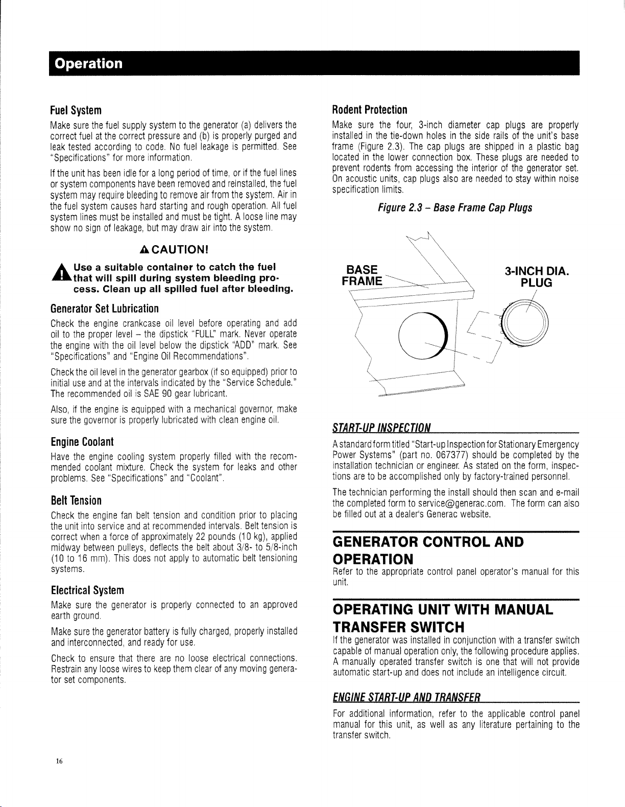
Operation
Fuel
System
Make
sure
the
fuel
supply
correct
fuelatthe
leak
tested
"Specifications"
If
the
unit
has
or
system
system
may
the
fuel
system
system
lines
shownosignofleakage,
correct
accordingtocode.Nofuel
for
more
been
idle
foralong
components
require
mustbeinstalled
have
bleedingtoremove
causes
systemtothe
pressure
information
been
hard
starting
and
but
may
generator
and
(b)isproperly
leakageispermitted.
periodoftime,orif
removed
draw
and
reinstalled,
air
from
the
and
rough
operation.
mustbetight A
air
into
the
(a)
the
system.
loose
system.
ACAUTIONI
A Use a suitable container to catch the fuel
....
that will spill during system bleeding process. Clean up all spilled fuel after bleeding.
Generator
Check
oiltothe
the
"Specifications"
Check
initial
The
Also,ifthe
sure
Engine
Have
mended
problems.
Belt
Check
the
unit
correct
midway
(10to16
systems.
Electrical
Make
earth
Make
and
Checktoensure
Restrain
tor
set
Set
Lubrication
the
engine
proper
level-the
engine
with
the
and
the
oil
levelinthe
use
andatthe
recommended
engineisequipped
the
governorisproperly
crankcase
oil
"Engine
intervals
oilisSAE90gear
oil
dipstick
level
below
Oil
Recommendations"
generator
indicatedbythe"
withamechanical
lubricated
level
befol'e
"FULL'
the
dipstick
gearbox
lubricant
with
Coolant
the
engine
cooling
coolant
mixture.
See
"Specifications"
system
Check
and
properly
the
system
"Coolant"
Tension
the
engine
fan
belt
tension
and
condition
into
service
andatrecommended
whenaforceofapproximately22pounds
between
mm).
pulleys,
This
does
deflects
the
not
applytoautomatic
belt
System
sure
the
generatorisproperly
ground.
sure
the
generator
interconnected,
that
any
loose
wirestokeep
components.
batteryisfUlly
and
ready
there
arenoloose
connectedtoan
for
use.
them
clearofany
charged,
operating
mark.
Never
"ADD"
(ifsoequipped)
Service
governor,
clean
engine
filled
with
for
leaks
priortoplacing
intervals.
about
electrical
Belt
(10
3/8-to5/8-inch
belt
properly
connections,
moving
delivers
the
purged
and
See
fuel
lines
the
fuel
Air
All
fuel
line
may
and add
operate
mark.
See
prior
to
Schedule."
make
oil.
the
recom-
and
other
tension
kg),
applied
tensioning
approved
installed
genera-
Rodent
Make
installedinthe
frame
locatedinthe
prevent
On
in
specification
STA8r-UP
A
Power
installation
tions
The
the
be
is
GENERATOR
Protection
sure
(Figure
rodents
acoustic
BASE
FRAME
standard
Systems"
aretobe
technician
completed
filled
outata
the
four,
3-inch
tie-down
2.3).
lower
from
units,
limits.
Figure
holesinthe
The
cap
connection
accessing
cap
plugs
2.3
-
diameter
plugs
also
Base
side
are
shippedina
box.
These
the
interiorofthe
are
neededtostay
Frame
cap
plugs
railsofthe
plugs
Cap
Plugs
3-INCH CIA.
INSPECTION
form
titled
"Start-up
(part
technicianorengineer.Asstatedonthe
accomplished
performing
formtoservice@generac.com.
dealer's
Inspection
no.
067377)
the
Generac
shouldbecompletedbythe
onlybyfactory-trained
install
should
website.
CONTROL
for
Stationary
then
AND
The
are
unit's
plastic
are
needed
generator
within
PLUG
Emergency
form,
personnel.
scan
and
form
properly
base
bag
to
set
noise
inspec-
e-mail
can
also
OPERATION
Refertothe
unit
OPERATING
TRANSFER
If
the
capableofmanual
A
manually
automatic
appropriate
generator
operated
start-up
control
UNIT
WITH
SWITCH
was
installedinconjunction
operation
and
transfer
does
only,
switchisone
not
panel
operator's
manual
MANUAL
withatransfer
the
following
includeanintelligence
procedure
that
will
not
circuit
for
this
switch
applies.
provide
ENGINE
For
manual
transfer
16
STA8T-UP
additional
for
this
switch.
AND
TRANSFE8
information,
unit,aswellasany
refertothe
applicable
literature
control
panel
pertainingtothe
Page 19
~
A The Maintenance Disconnect Switch and
....
the AUTO/OFF/MANUAL switches (if so
equipped) must be set properly, or the
generator will crank and start as soon as
the UTILITY power to the transfer switch is
turned off. Refer to applicable control panel
and transfer switch manuals for more infor-
mation.
A Do not proceed until certain that utility
....
source voltage is available to the transfer
switch and the transfer switch main contacts
are set to UTILITY.
/r\ Do not attempt manual operation until all
illpower
been positively turned off,
gerous - possibly lethal - electrical shock
will result.
/i).
Transfer switch enclosure doors should be
~kept
personnel should be allowed access to the
transfer switch Interior. Extremely high and
dangerous voltages are present in the trans-
fer switch.
In
ordertomanually
generator,
•
Turn
switch,
main
•
Set
load
•
Set
breakertoits
•
Start
•
Let
•
Check
certain
manual
load
•
Set
breakertoitsON(or
•
Load
generator.
RETRANSFER
For
additional
manual
transfer
To
manually
shut
down
•
Set
breakertoits
•
Manually
MAL)
supplies to the transfer switch have
or
extremely dan-
closed and locked. Only authorized
transfer
follow
these
OFFordisconnect
using
the
means
line
circuit
breaker).
the
transfer
circuits
the
the
engine
all
that
circuits
the
circuits
for
switch.
the
position,
handletoits
connectedtothe
stationary
OFF
(or
generator.
stabilize
applicable
all
readings
handletoits
suppliedbythe
stationary
are
now
AND
SHUTDOWN
information,
this
unit,aswellasany
transfer
the
stationary
move
the
generator,
OFF
(or
the
i.e.,
and
transfer
load
directions:
the
utility
provided
UTILITY
utility
emergency
OPEN)
position.
warm
up.
instrument
are
correct,
STANDBY
generator.
emergency
CLOSED)
poweredbythe
refertothe
load
backtothe
follow
these
emergency
OPEN)
position.
switch
load
cirCUits
from
the
power
circuittothe
(suchasthe
(NORMAL)
power
generator's
and
gauge
move
(GENERATOR)
generator's
position.
stationary
applicable
literature
utility
directions:
generator's
handletoits
connectedtothe
utility
sourcetothe
utility
position
supply.
main
readings.
the
transfer
position,
main
control
pertainingtothe
power
main
UTILITY
utility.
transfer
source
with
line
circuit
When
switch
i.e,
line
circuit
emergency
panel
source
and
line
circuit
(NOR-
•
TurnONthe
the
means
circuit
•
Let
the
internal
•
Shut
OPERATING
TRANSFER
If
the
generator
switch,
suchasa
stopped
Refertothe
"Transfer
note
the
SERVICE
AUTHORIZED
Every
Monthor100Hours
•
Test
stationary
•
Inspect
•
Check
•
Check
•
Check
•
Check
•
Test/inspect
Every
Three
•
Inspect
•
Inspect
•
Inspect/test
AUTHORIZED
utility
power
provided
breaker)
generator
temperatures.
down
the
(suchasthe
.
runatno-load
generator.
UNIT
SWITCH
has
been
installed
GTS-type
automaticallyormanually.
applicable
Switch
Start
Signal
dangers
under
"Engine
SCHEDULE
OPERATOR
emergency
battery
(batteries)
engine
oil
level.
gearbox
engine
generator
oil
level
coolant
level.
ground
starting
aids.
MonthsorEvery
and
test
fuel
system
exhaust
fuel
system.
supply
SERVICE
FUNCTIONS
After
First30HoursofOperation
•
Inspect
Wiring.
•
Change
engine
crankcase
•
Inspect
engine
fan
belts.
•
Inspect
battery
(batteries)
Every
Six
MonthsorEvery
•
Lubricate
•
Service
•
Service
•
InspectACgenerator.
•
Test
•
Inspect
•
Check
•
Inspect
engine
engine
engine
engine
fan
engine
engine
air
fuel
safety
belts.
coolant
cooling
controls.
cleaner.
filter.
controls.
level.
Maintenance
supplytothe
WITH
along
switch,
NOTE:
manual
for
Connections".Inaddition,
Start-up
MAINTENANCE
(whichever
generator
and
cables.
(ifsoequipped).
connections.
120
and
system.
TECHNICIAN
oil
and
and
cables.
200
system
hoses.
transfer
utility
power
forafew
minutestostabilize
AUTOMATIC
withanautomatic
the
engine
the
transfer
and
FUNCTIONS
comes
first)
system.
Hours
(whichever
connections.
MAINTENANCE
oil
filter.
Hours
(whichever
switch,
source
main
transfer
maybestarted
switch
and
please
Transfer."
comes
comes
first)
using
line
and
to
first)
17
Page 20
Maintenance
•
Check
optional
•
Check
battery
•
Check
engine
•
Check
electrical
•
Check/test
•
Perform
AnnuallyorEvery
•
Change
•
Inspect
•
Test
engine
•
Drain
water
•
Retorque
•
Drain
and
Every
Two
•
Replace
•
Replace
•
Inspect
•
Drain,
flush,
Every
1,000
•
Inspect
•
Inspect
•
Retorque
•
Remove/test
•
Remove/test
As
Required
•
Bleed
engine
PERIODIC
A
rigorous
be
established
diligently,
functions
Keepinga"Maintenance
log
shouldbea
gauge
and
The
manufacturer
be
established
ing
Authorized
053263),anAuthorized
engine
running
vals.
AskanAuthorized
The
tasks
recommended
Note
that
tobeperformed
capacities
specifications,
starting
(batteries).
compression.
connections.
annunciator
operational
test
600
engine
oil
and
all
wiring.
starter
operation.
from
fuel
fan
bolts.
refill
gearbox
Years
all
rubber
hoses.
engine
fan
belts.
the
Stationary
refill
cooling
Operating
engineDCalternator.
engine
starter.
engine
mounting
fuel
injection
cooling
system
fuel
system.
MAINTENANCE
programofscheduled
and
maintained.
will
provide
properly
instrument
between
listedinthe
maintenance
manyofthe
and
are
added
whenitis
continuous
readings
requires
the
Service
tests
and
tests
onlybyan
recommendations,aswellasother
listedin"Specifications".
aids.
panel.
Hours
(whichever
filter.
tank.
(ifsoequipped).
Emergency
system.
Generator
Hours
brackets.
pump.
thermostat.
periodic
Suchaprogram,ifadhered
assurance
needed.
Log"ishighly
recordofrepairs,
during
thata"Scheduled
userofthis
Dealer.
Under
Service
Technician
checksatsix-month
Service
Dealer
"Service
requirements
and
checks
Authorized
that
recommended.
operational
equipment
this
about
Schedule"
for
listedinthe
Service
comes
first)
System.
maintenance
the
power
parts
tests,
Maintenance
and
agreement,
performs
and
one-year
this
agreement
cover
this
equipment.
Technician.
should
to
system
Such
a
replacements,
etc.
Plan"
the
install-
(Part
No.
prestart
the
schedule
and
inter-
minimum
are
Fluid
applicable
TEST
STATIONARY
OPERATION
An
authorized
ary
emergency
monthly
fer
inspecting
Generator");
During
shouldberecordedina
also
30
Every
should
INSPECT
(or
100
switch
for
wiring
this
operational
shouldbetestedatthis
minutes
and
six
months
performasystem
BAUERY
EMERGENCY
AND
COMPONENTS
operator
evidenceofarcing,
and
should
generator
hours).
This
and
grounding
ensuring
test,
any
discrepancies
(or
200
system
that
"Maintenance
time;
hours),anAuthorized
operational
GENERATOR
test
the
operationofthe
and
should
include
and
pittedorburned
connections
starting
all
instrument
Log."
the
engine
corrected
test
SYSTEM
inspect
devices
its
components
inspecting
(see
and
The
shouldberunatleast
immediately.
Service
the
contacts;
"Grounding
are
operational.
gauge
readings
transfer
Technician
station-
trans-
system
A Stationary emergency generators Installed
....
with automatic transfer switches will crank
and start automatically when NORMAL (UTIL-
ITY) source voltage Is removed or Is below
an
acceptable preset level.Toprevent such
automatic start-up and possible Injury to
personnel, do not connect battery cables
until certain that normal source voltage at
the transfer switch Is correct and the system
Is ready to be placed Into operation.
A Storage batteries give off explosive hydrogen
~gas.
This gas can form an explosive mixture
around the battery for several hours after
charging. The slightest spark can Ignite the
gas and cause
sion can shatter the battery and cause blind-
ness or other Injury. Any area that houses a
storage battery must be properly ventilated.
Do
not allow smoking, open flame, sparks or
any spark producing tools or equipment near
the battery.
an
explosion. Suchanexplo-
A Battery electrolyte fluid Is an extremely
....
caustic sulfuric acid solution that can cause
Do
severe burns.
eyes, skin, clothing, painted surfaces, etc.
Wear protective goggles, protective clothing
and gloves when handling
Is spilled, flush the affected area Immediately with clear water.
not permit fluid to contact
a battery. If fluid
IAWARNINGII
A
Do
not dispose of the batteryIna fire. The
~battery
A
Do
....
Released electrolyte can be toxic and harmful to the skin and eyes.
Is capable of exploding.
not open or mutilate the battery.
the
18
Page 21
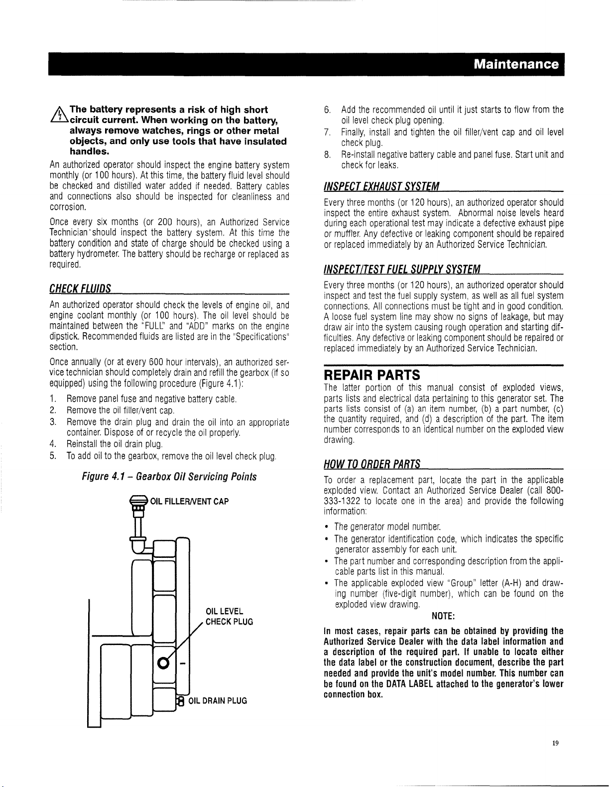
/;\
The battery represents a risk of high short
illcircuit
always remove watches, rings or other metal
objects, and only use tools that have insulated
handles.
An
authorized
monthly
be
checked
and
connections
corrosion.
Once
Technician
battery
battery
required.
CHECK
An
authorized
engine
maintained
dipstick.
section.
Once
annually
vice
technician
equipped)
1.
Remove
2.
Remove
3.
Remove
container.
4.
Reinstall
5.
To
current. When working on the battery,
operator
(or
100
and
every
six
'should
condition
hydrometer.
should
hours).Atthis
distilled
months
and
water
also
shouldbeinspected
(or
200
inspect
the
stateofcharge
The
battery
inspect
the
engine
time,
the
battery
addedifneeded.
hours),anAuthorized
battery
system.Atthis
shouldbechecked
shouldberechargeorreplaced
FLUIDS
operator
coolant
between
Recommended
(oratevery
should
using
panel
the
the
Disposeofor
the
add
oiltothe
Figure
should
monthly
the
the
following
fuse
oil
filler/Vent
drain
oil
drain
gearbox,
(or
100
"FULl:'
fluids
600
completely
procedure
and
negative
cap.
plug
and
recycle
plug.
4.1-Gearbox
OIL
check
the
levelsofengine
hours).
and
are
hour
drain
remove
FILLERNENT
The
"ADD"
marksonthe
listed
areinthe
intervals),anauthorized
drain
and
refill
(Figure
battery
the
oil
the
oil
properly.
the
oil
Oil
Servicing
OIL
CHECK
battery
fluid
Battery
for
cleanliness
oil
level
"Specifications"
the
4.1):
cable.
intoanappropriate
level
check
Points
CAP
LEVEL
PLUG
system
level
Service
time
using
oil,
should
gearbox
plug.
should
cables
and
the
as
and
be
engine
ser-
(if
so
Maintenance
6.
Add
the
recommended
oil
level
check
plug
7.
Finally,
install
and
check
plug.
8.
Re-install
check
INSPECT
Every
three
inspect
during
or
a
muffler.
or
replaced
INSPECT/TEST
Every
three
inspect
connections.
A
loose
draw
air
ficulties.
replaced
REPAIR
The
latter
parts
lists
parts
lists
the
quantity
number
drawing.
HOWTOORDER
To
orderareplacement
exploded
333-1322tolocate
information:
•
The
•
The
generator
•
The
cable
•
The
ing
exploded
In
most
Authorized
a
descriptionofthe
the
data
needed
be
foundonthe
connection
negative
for
leaks.
EXHAUST
months
the
each
Any
immediatelybyan
(or
entire
exhaust
operational
defectiveorleaking
FUEL
months
and
fuel
into
Any
immediatelybyan
(or
test
the
fuel
All
connections
system
the
system
defectiveorleaking
PARTS
portionofthis
and
electrical
consistof(a)anitem
required,
correspondstoan
PARTS
view.
ContactanAuthorized
generator
generator
part
parts
applicable
number
cases,
and
model
identification
assembly
number
listinthis
exploded
(five-digit
view
drawing.
repair
Service
labelorthe
provide
DATA
box.
and
oil
untilitjust
opening.
tighten
the
battery
cable
SYSTEM
120
hours),anauthorized
system.
test
may
indicateadefective
Authorized
SUPPLY
120
supply
line
may
causing
data
and
oneinthe
number.
for
corresponding
manual.
parts
Dealer
required
construction
the
LABEL
SYSTEM
hours),anauthorized
system,aswellasall
mustbetight
shownosignsofleakage,
rough
component
Authorized
manual
pertainingtothis
number,
(d)adescriptionofthe
identical
part,
locate
area)
code,
each
unit.
view
"Group"
number),
NOTE:
canbeobtainedbyproviding
with
the
part.Ifunabletolocate
unit's
model
attachedtothe
startstoflow
oil
filler/Vent
and
Abnormal
component
operation
Service
consistofexploded
numberonthe
the
Service
and
which
description
which
data
document,
number.
cap
and
panel
fuse.
Start
operator
noise
levels
exhaust
shouldberepaired
Service
Technician.
operator
andingood
and
shouldberepaired
Technician.
generator
(b)apart
part.
exploded
partinthe
Dealer
provide
the
indicates
from
letter
(A-H)
canbefoundonthe
label
information
describe
This
number
generator's
from
oil
unit
should
heard
should
fuel
system
condition.
but
starting
views,
set.
number,
The
view
applicable
(call
800-
following
the
specific
the
appli-
and
draw-
either
the
lower
the
level
and
pipe
may
dif-
or
The
(c)
item
the
and
part
can
19
Page 22
Maintenance
500
KW
TO
600
KW
STATIONARY
EMERGENCY
DIESEL
ENGINE
DRIVEN
GENERATOR
FollowingIsa
size.
The
tobedecreased
occurs
NOTE:
A
To
~
control panel Auto-Oft-Manual switch to the "Off' position, removing the control panel fuse, turning
oft the battery charger, and removing the negative battery cable before performing any maintenance.
NOTE: The battery charger must be turned oft BEFORE removing the battery cable to prevent an
current condition from burning out sensitive control panel components and circuits. Following all
maintenance,
when required.
recommended
established
first,
from
Add
20%toall
prevent injury, disable the generator set from starting and/or connecting to the load by setting the
SERVICE
SETS
maintenance
intervalsinthe
(performed
the
more
frequently)ifthe
previous
maintenance
times
noted
reverse these steps to insure the unit Is returned to standby setup for normal operation
MAINTENANCE
schedule
schedule
for12cylinderorlarger
for
stationary
are
the
maximum
unitisusedina
intervaltodetermine
INTERVAL
emergency
required
severe
the
next
engines.
14
WARNINGll
when
the
application.
required
diesel
INFORMATION
engine
driven
unitisusedinan
Use
the
maintenance
generator
average
unit
hour
interval.
sets
from
500kWto
service
application.
meterorcalendar
They
time,
600kWin
will
need
whichever
over
The
various
service
maintenance
1.
An
early
inspectionofthe
monthlyorfollowing
1A.A
break-in
identify
of
the
2.
An
problem
per
3.Amid-level
problem
unittocomplete.
4.Acomprehensive
andtoidentify
approximately
service
any
potential
unit
and
requires
operational
unittocomplete.
inspectionofthe
areas.
Performed
inspectionofthe
areas.
Performed
any
8.0
intervals
generator
each10hoursofoperationofthe
inspectionofthe
problem
approximately
semi-annuallyorfollowing
generator
annually
inspectionofthe
potential
man-hours
problem
are
settoinsureitis
generator
areas.
Performed
2.5
generator
settoinsureitis
or
generator
areas.
per
unittocomplete.
designatedbyinterval
man-hours
settoinsureitis
settoinsureitis
Performed
numbersasfollows:
readytooperate
unit
and
settoinsureitis
ONLY
ONCE
following
per
unittocomplete.
readytooperate
each50hoursofoperationofthe
each
100
hoursofoperationofthe
biannuallyorfollowing
when
requires
readytooperate,
the
to
operate
properly
serviced
required
approximately.5man-hours
first
and
six
monthsorthe
and
carry
carry
and
each
andtoidentify
transfer
to,
and
the
load
when
unit
and
the
load
when
unit
and
requires
readytooperate
250
hoursofoperationofthe
any
carry
first50hoursofoperation
required,
requires
required,
potential
per
problem
unittocomplete.
the
load
andtoidentify
approximately
andtoidentify
approximately
and
carry
the
areas.
when
required,
after
any
1.5
any
4.aman-hours
load
when
unit
and
Performed
and
to
purchase
potential
man-hours
potential
per
required,
requires
20
Page 23
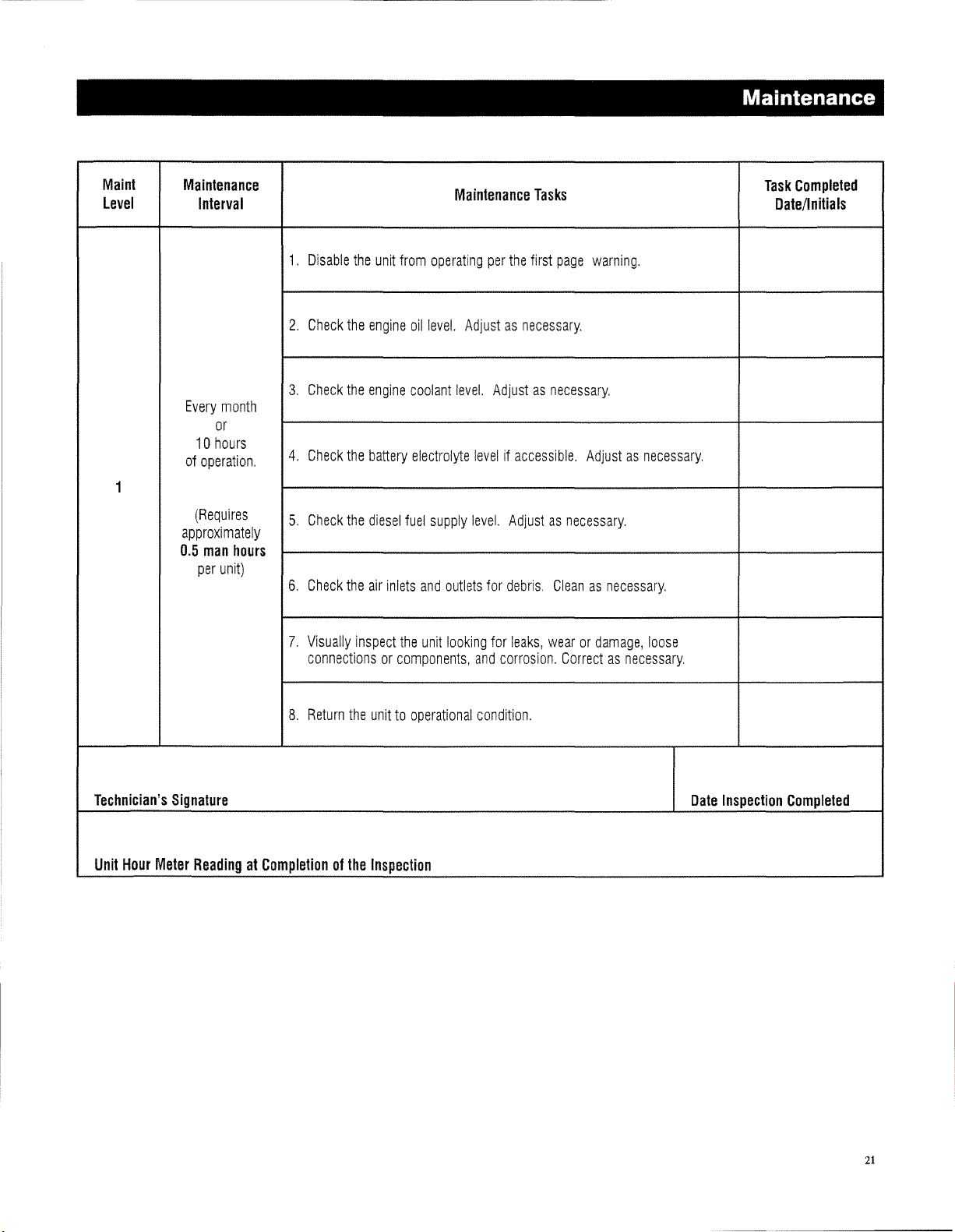
Maintenance
Maint
level
1
Maintenance
Interval
Every
month
or
10
hours
of
operation.
(Requires
approximately
0.5
man
hours
per
unit)
1.
2.
3.
4.
5.
6.
Disable
Check
Check
Check
Check
Check
the
the
the
the
the
the
unit
engine
engine
battery
diesel
air
inlets
from
operating
oil
level.
coolant
electrolyte
fuel
supply
and
Maintenance
Adjustasnecessary.
level.
levelifaccessible.
level.
outlets
for
Tasks
per
the
first
Adjustasnecessary.
Adjustasnecessary.
debris.
page
warning.
Adjustasnecessary.
Cleanasnecessary.
Task
Completed
Date/Initials
Technician's
Unit
Hour
Meter
7.
Visually
connectionsorcomponents,
8.
Return
Signature
ReadingatCompletionofthe
inspect
the
unit
the
unittooperational
Inspection
looking
and
condition.
for
leaks,
corrosion.
wearordamage,
Correctasnecessary.
loose
Date
Inspection
Completed
21
Page 24
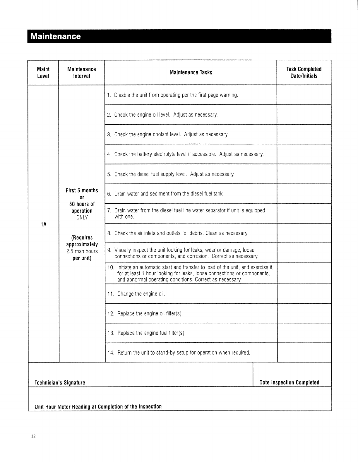
Maintenance
Maint
Level
Maintenance
Interval
1.
2.
3,
4,
5,
Disable
Check
Check
Check
Check
the
the
the
the
the
unit
engine
engine
battery
diesel
from
operating
oil
level.
coolant
electrolyte
fuel
supply
Maintenance
Adjustasnecessary.
level.
levelifaccessible,
level.
Tasks
per
the
first
page
Adjustasnecessary,
Adjustasnecessary.
warning.
Adjustasnecessary,
Task
Completed
Date/lnitials
1A
First6months
or
50
hours
of
operation
ONLY
(Requires
approximately
2,5
man
hours
per
unit)
6,
Drain
water
and
sediment
Drain
water
from
7.
with
one,
8,
Check
the
g,
Visually
connectionsorcomponents,
1O,
11,
12,
13.
14,
inspect
Initiateanautomatic
foratleast1hour
and
abnormal
Change
Replace
Replace
Return
the
the
air
inlets
and
the
unit
looking
operating
the
engine
the
engine
the
engine
unittostand-by
diesel
outlets
looking
start
oil.
oil
fuel
from
the
diesel
fuel
line
water
for
debris,
for
leaks,
and
corrosion,
and
transfertoloadofthe
for
leaks,
loose
conditions,
filter(s),
setup
Correctasnecessary,
for
fuel
tank.
separatorifunitisequipped
Cleanasnecessary,
wearordamage,
Correctasnecessary,
connectionsorcomponents,
operation
when
loose
unit,
and
required,
exercise
it
Technician's
Unit
Hour
22
Signature
Meter
ReadingatCompletionofthe
Inspection
Date
Inspection
Completed
Page 25
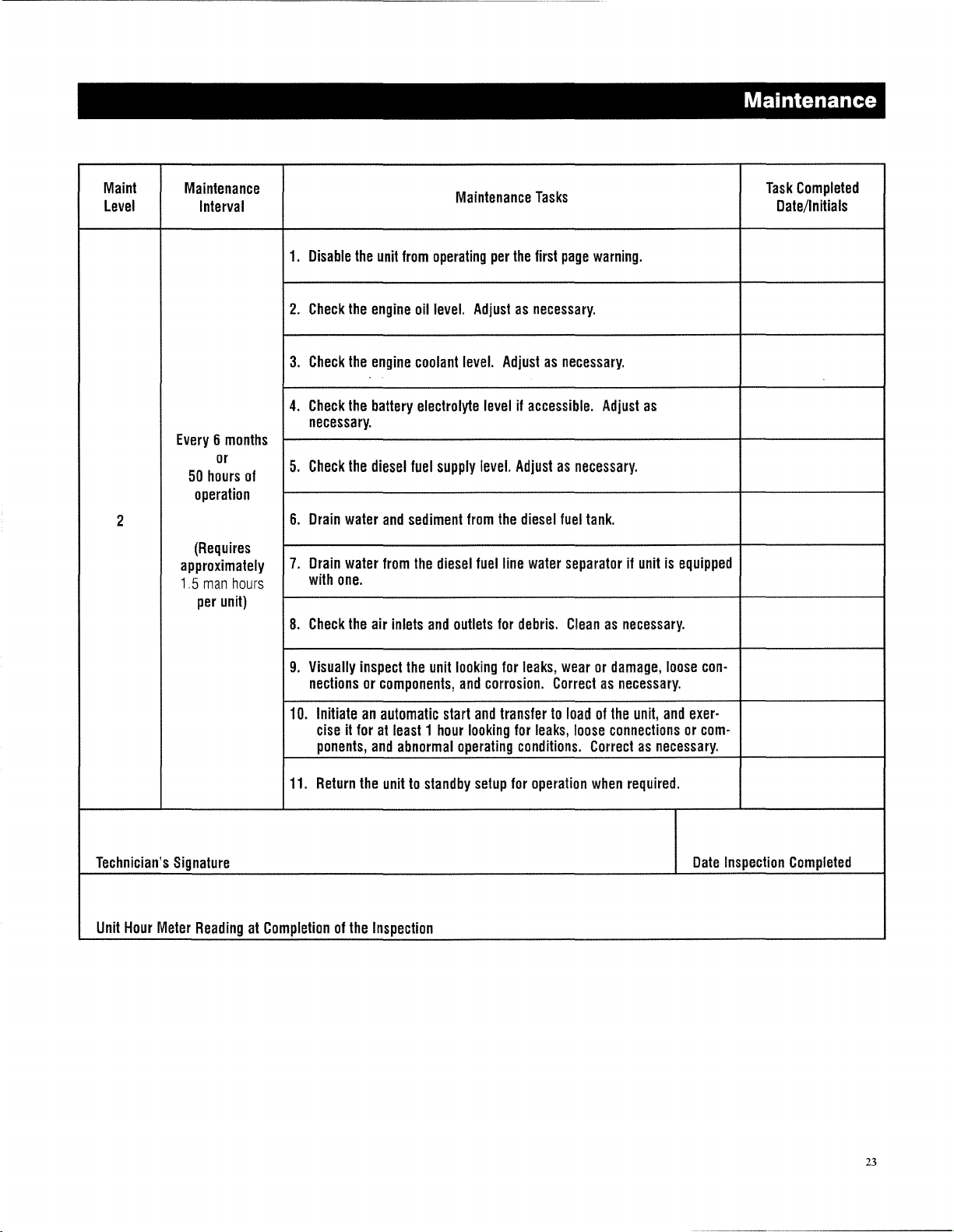
Maint
Level
2
Maintenance
Interval
Every6months
or
50
hours
of
operation
(Requires
approximately
1.5
man
hours
per
unit)
1.
Disable
2.
Check
3.
Check
4.
Check
necessary.
5.
Check
6.
Drain
7.
Drain
with
8.
Check
the
the
the
the
water
water
one.
the
the
unit
from
engine
engine
battery
diesel
and
from
air
inlets
operating
oil
level.
coolant
electrolyte
fuel
supply
sediment
the
diesel
and
outlets
Maintenance
Adjustasnecessary.
level.
levelifaccessible.
level.
from
fuel
Tasks
per
the
first
Adjustasnecessary.
Adjustasnecessary.
the
diesel
line
water
for
debris.
page
warning.
Adjust
as
fuel
tank.
separatorifunitisequipped
Cleanasnecessary.
Maintenance
Task
Completed
Date/Initials
Technician's
Unit
Hour
Meter
9.
Visually
nectionsorcomponents,
10.
11.
Signature
ReadingatCompletionofthe
inspect
the
unit
Initiateanautomatic
ciseitforatleast1hour
ponents,
Return
and
the
unittostandby
Inspection
start
abnormal
looking
for
leaks,
and
corrosion.
and
transfertoloadofthe
looking
for
operating
setup
conditions.
for
wearordamage,
Correctasnecessary.
unit,
leaks,
loose
connectionsorcom-
Correctasnecessary.
operation
when
required.
loose
and
con-
exer-
Date
Inspection
Completed
23
Page 26
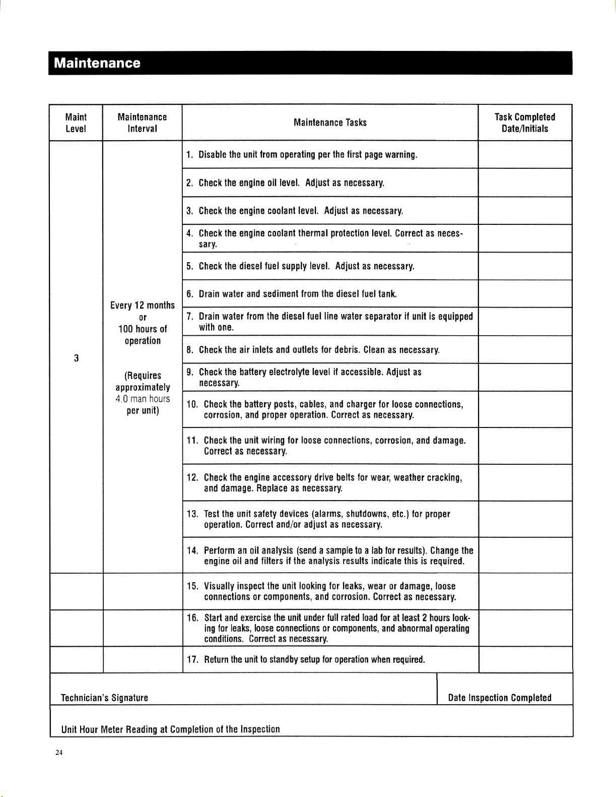
Maintenance
Maint
level
3
Maintenance
Interval
Every12months
or
100
hours
of
operation
(Requires
approximately
4,0
man
hours
per
unit)
Disable
1.
Check
2.
3.
Check
4.
Check
sary.
Check
5.
Drain
6.
Drain
7.
with
Check
8.
Check
9.
necessary.
10.
Check
corrosion,
the
the
the
the
water
water
one.
the
the
the
engine
engine
engine
diesel
air
battery
the
unit
from
and
from
inlets
battery
and
proper
operating
oil
level.
coolant
coolant
fuel
supply
sediment
the
diesel
and
outlets
electrolyte
posts,
operation.
Maintenance
Adjustasnecessary.
level.
thermal
level.
from
fuel
levelifaccessible.
cables,
Tasks
per
the
first
Adjustasnecessary.
protection
Adjustasnecessary.
the
diesel
line
water
for
debris.
and
charger
Correctasnecessary.
page
warning.
level.
Correctasneces-
fuel
tank.
separatorifunitisequipped
Cleanasnecessary.
Adjust
as
for
loose
connections,
Task
Completed
Date/lnitials
Technician's
Unit
Hour
Meter
11.
12.
13.
14.
15.
16.
17.
Signature
ReadingatCompletionofthe
Check
the
unit
wiring
for
loose
Correctasnecessary.
Check
the
engine
accessory
and
damage.
Test
the
operation.
Performanoil
engine
Visually
connectionsorcomponents,
Start
and
ing
for
conditions.
Return
Replaceasnecessary.
unit
safety
devices
Correct
oil
and
inspect
exercise
leaks,
the
unittostandby
Inspection
and/or
analysis
filtersifthe
the
unit
the
unit
loose
connectionsorcomponents,
Correctasnecessary.
adjustasnecessary.
(sendasampletoa
looking
under
setup
connections,
drive
belts
(alarms,
analysis
for
and
corrosion.
full
for
operation
corrosion,
for
wear,
shutdowns,
lab
results
indicate
leaks,
wearordamage,
Correctasnecessary.
rated
load
when
and
damage.
weather
etc.)
for
results).
foratleast2hours
and
abnormal
required.
cracking,
for
proper
Change
thisisrequired.
loose
operating
the
look-
Date
Inspection
Completed
24
Page 27
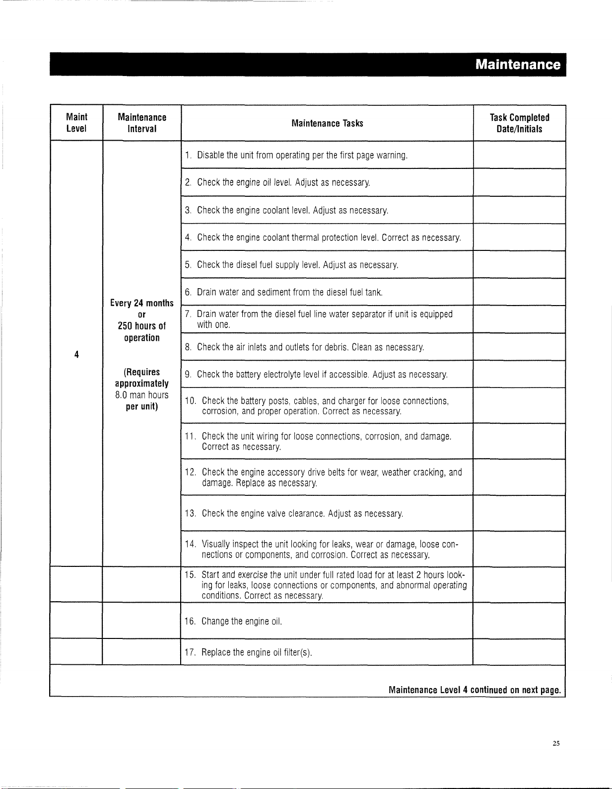
Maintenance
Maint
level
4
Maintenance
Interval
Every24months
or
250
hours
of
operation
(Requires
approximately
8.0
man
hours
per
unit)
1.
2.
3.
4.
5.
6.
7.
8.
9.
10.
Disable
Check
Check
Check
Check
Drain
Drain
with
Check
Check
the
the
the
the
the
water
water
one.
the
the
Check
the
corrosion,
unit
engine
engine
engine
diesel
and
from
air
inlets
battery
battery
and
from
operating
oil
level.
coolant
coolant
fuel
supply
sediment
the
diesel
and
electrolyte
posts,
proper
Maintenance
per
Adjustasnecessary.
level.
thermal
level.
from
the
fuel
outlets
for
levelifaccessible.
cables,
operation.
Tasks
the
first
Adjustasnecessary.
protection
Adjustasnecessary.
diesel
line
water
debris.
and
charger
Correctasnecessary.
page
warning.
level.
Correctasnecessary.
fuel
tank.
separatorifunitisequipped
Cleanasnecessary.
Adjustasnecessary.
for
loose
connections,
Task
Completed
Datellnitials
11.
Check
the
unit
Correctasnecessary.
12.
Check
the
engine
damage.
13.
Check
14.
Visually
nectionsorcomponents,
15.
Start
ing
conditions.
16.
Change
17.
Replace
Replaceasnecessary.
the
engine
inspect
and
exercise
for
leaks,
loose
CorrectasnecessalY
the
engine
the
engine
wiring
for
loose
connections,
accessory
valve
the
unit
the
connectionsorcomponents,
oil.
oil
drive
clearance.
looking
and
corrosion.
unit
under
filter(s).
belts
Adjustasnecessary.
for
leaks,
full
rated
corrosion,
for
wear,
wearordamage,
Correctasnecessary.
load
foratleast2hours
and
damage.
weather
and
cracking,
loose
abnormal
Maintenance
and
con-
look-
operating
Level4continuedonnext
page.
25
Page 28
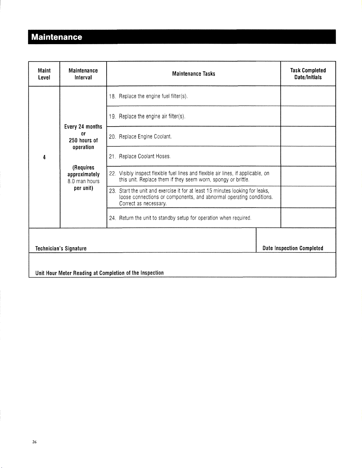
Maintenance
Maint
Level
Maintenance
Interval
Maintenance
Tasks
Task
Completed
Date/lnitials
Every24months
4
Technician's
or
250
hours
of
operation
(Requires
approximately
8.0
man
hours
per
unit)
Signature
Replace
18.
Replace
19.
Replace
20.
Replace
21
Visibly
22.
this
Start
23.
loose
Correctasnecessary.
Return
24.
the
the
Engine
Coolant
inspect
unit.
Replace
the
unit
connectionsorcomponents,
the
unittostandby
engine
fuel
filter(s).
air
filter(
s).
Coolant.
Hoses.
flexible
fuel
lines
and
flexible
themifthey
and
exerciseitforatleast15minutes
seem
setup
worn,
and
for
operation
air
lines,ifapplicable,
spongyorbrittle.
abnormal
operating
when
looking
required.
on
for
leaks,
conditions.
Date
Inspection
Completed
Unit
26
Hour
Meter
ReadingatCompletionofthe
Inspection
Page 29
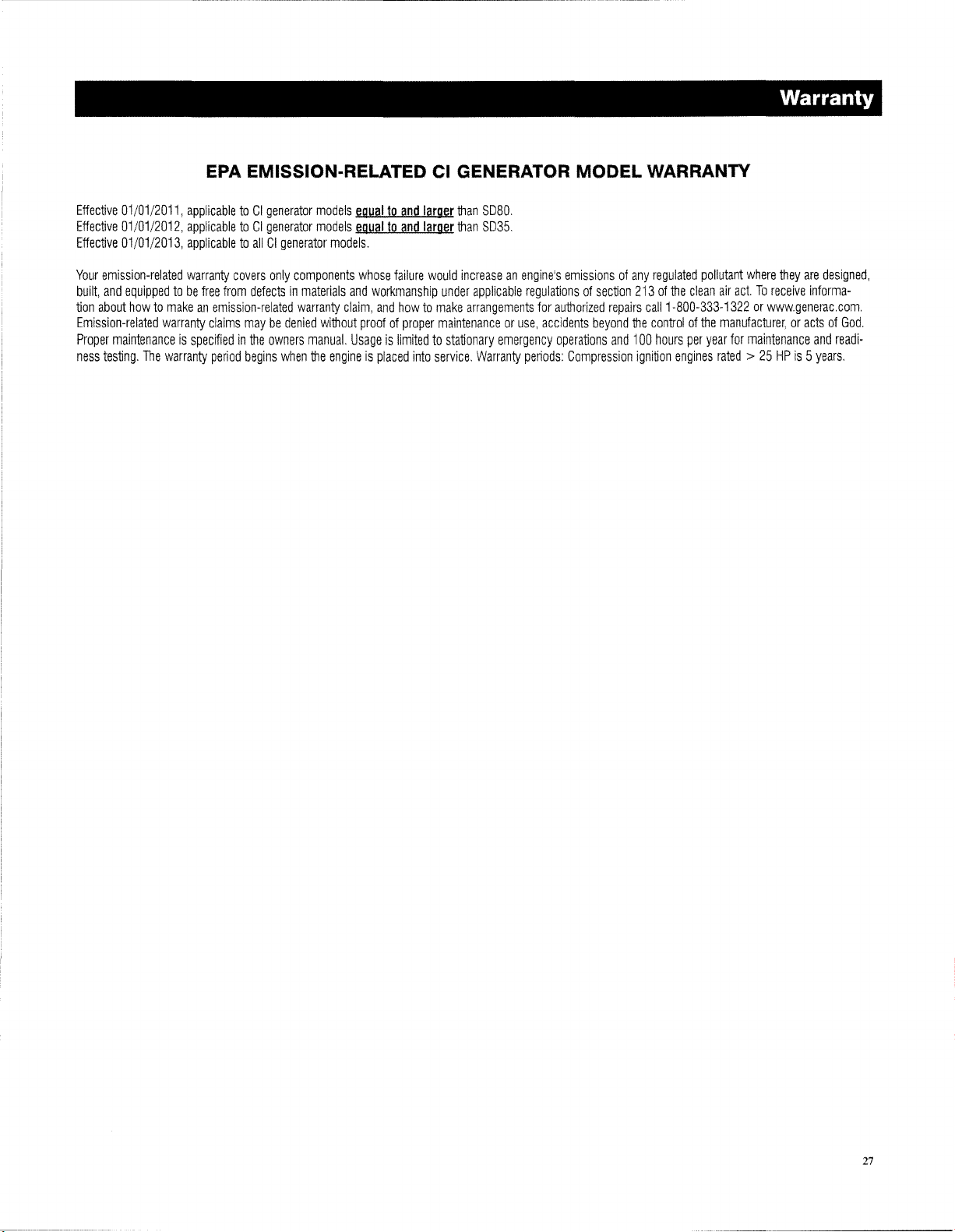
Effective
01/01/2011,
Effective
01/01/2012,
Effective
01/01/2013,
Your
emission-related
built,
and
equippedtobe
tion
about
howtomakeanemission-related
Emission-related
Proper
maintenanceisspecifiedinthe
ness
testing.
The
warranty
warranty
EPA EMISSION-RELATED CI GENERATOR MODEL WARRANTY
applicabletoCI
applicabletoCI
applicabletoallCIgenerator
warranty
free
claims
period
generator
generator
covers
only
from
defectsinmaterials
maybedenied
owners
begins
when
models
models
models.
components
and
warranty
claim,
without
manual.
Usageislimitedtostationary
the
engineisplaced
equaltoand
equaltoand
whose
failure
workmanship
and
howtomake
proofofproper
into
larger
than
SD80
larger
than
SD35.
would
increaseanengine's
under
applicable
arrangements
maintenanceoruse,
emergency
service.
Warranty
emissionsofany
regulationsofsection
for
authorized
accidents
operations
periods:
repairs
beyond
and
Compression
regulated
213ofthe
the
100
ignition
clean
call
1-800-333-1322orwwwgenerac.com.
controlofthe
hours
per
engines
Warranty
pollutant
where
they
are
air
act.Toreceive
manufacturer,oractsofGod.
year
for
maintenance
rated>25HPis5
informa-
and
years.
designed,
readi-
27
Page 30
Warranty
Effective
01/01/2011,
Effective
01/01/2012,
Effective
01/01/2013,
NOTE: This Emission Control Warranty Statement applies only to mobile (trallerlzed) non-road diesel engine powered
generators (model year 2000) as follows: The
this statement pertains to this product only IF the generator
applicabletoCI
applicabletoCI
not
applicabletoCI
generator
generator
generator
models
models
models.
eguilila
eguiliia
EPA
ilnd
smilllQ[
than
S060.
and
smallQr
than
S030.
portion of this statement pertains to this product; The CARB portion of
size Is (1) 15 kW or below OR (2) 130 kW or greater.
CALIFORNIA
The
California
(Generac),
designed,
control
improper
Your
emission
nectors
labor,
Emission
first.Inthe
engineisfoundtobe
As
the
Owner's
Generac
As
the
if
your
useofcounterfeit
Your
engineisdesignedtooperateondiesel
California
You
warranty
Warranty
Authorized
Air
Resources
are
pleasedtoexplain
built
and
systemonyour
maintenanceofyour
and
shouldawarrantable
equippedtomeet
control
other
system
emission-related
non-road
condition
MANUFACTURER'S
control
systemson1996
absenceofan
non-road
Manual.
cannot
deny
non-road
non-road
are responsible for contacting a Generac Authorized Warranty Service Facility as soon as a problem occurs.
diesel
diesel
emission
repairs
shouldbecompletedina
service
Warranty
hourmeter,
defectiveinmaterialsorworkmanship,
diesel
engine
For
warranty
warranty
engine
engine,ora
and/or
"grey
requirements.
canbearrangedbycontacting
Service
AND
FEDERAL
YOUR
WARRANTY
Board
(CARB)and
the
stringent
diesel
non-road
may
include
assemblies
occur.
Emission
engine
diesel
such
the
United
Control
anti-smog
for
the
periodsoftime
engine.
partsasthe
Generac
States
System
standards
fuel
will
EMISSION
and
later
model
year
the
said
coverageisfive
non-road
repairsorreplacement
PURCHASER'S/OWNER'S
purchaser/owner,
purposes,
solely
duetolackofreceiptsorfor
purchaser/owner,
parVcomponent
market"
parts
Facility
nearest
you
Generac
you
not
made,
fuel
only
reasonable
you,
call
are
responsible
recommends
should,
however,beaware
has
suppliedorapprovedbyGenerac.
Useofany
amountoftime,
either
your
our
toll-free
EMISSION
RIGHTS
Environmental
Warrantyonyour
for
the
stateofCalifornia
listed
below
injection
repair
years
that
failed
selling
system
your
non-road
CONTROL
diesel
engines
If,
during
WARRANTY
for
the
you
retain
your
failuretoensure
duetoabuse,
other
fuel
may
nottoexceed30days.
dealerora
number:
CONTROL
AND
OBLIGATIONS
Protection
new
provided
and
diesel
SYSTEM
are
said
warranty
willbeperformedbya
completionofall
all
receipts
that
Generac
resultinyour
Generac
Agency
non-road
and
there
the
air
induction
enginealno
warranted
period,
RESPONSIBILITIES:
covering
the
completionofall
may
neglect,
improper
Authorized
WARRANTY
(EPA),
diesel
the
federal
has
WARRANTY
for
required
maintenanceofyour
deny
enginenolonger
together
engine.*
government.
beennoabuse,
system.
costtoyou
Also
COVERAGE:
five
years,or3,000
any
emission-related
Generac
maintenanceaslistedinyour
scheduled
any
and/or
maintenanceorunapproved
Warranty
STATEMENT
with
Generac
New
non-road
Generac
neglect,
included
for
diagnosis,
hoursofuse,
componentorsystemonyour
Authorized
non-road
maintenance.
all
warranty
operatingincompliance
Service
Facility.Tolocate
Power
diesel
will
warrant
unapproved
maybehoses,
replacement
Warranty
diesel
coverageorresponsibility
modifications.,orthe
Systems,
engines
the
emission
modification
belts,
paris
whichever
Service
factory
engine.
However,
with
federal
the
Inc.
must
be
or
con-
and
occurs
Facility.
supplied
or
The
Generac
1·800·333·1322
IMPORTANT NOTE:
whichisprovidedtoyoubyGenerac
whichisenclosed
new
non-road
circumstances
obligations
Warranty
showing
If you have any questions regarding your warranty rights and responsibilities, you should contact Generac at the
following address:
Part 1
28
diesel
where
with
respecttoyour
service
canbeperformed
the
dateofsaletothe
This
herewithona
engine.Ifthereisany
the
separate
Generac
new
original
Warranty
onlybya
statement
pursuanttofederal
sheet,
conflictinterms
non-road
purchaser/owner.
explains
also
providedtoyoubyGenerac.
may
providealonger
diesel
engine
Generac
your
and
Authorized
rights
California
between
warranty
Warranty
ATTENTION
GENERAC
211
EAGLE,WI53119
and
obligations
law.
See
also
the
ECS
The
Warranty
period.
Service
WARRANTY
POWER
SYSTEMS,
MURPHY
DRIVE
under
"Generac
Warranty
and
the
the
ECS
When
the
Limited
Generac
Warranty
requesting
the
ECS
Both
Facility.
DEPARTMENT
INC.
Emission
Warranties
applies
Warranty,
and
warranty
Control
only
the
System
for
to
the
emission
the
ECS
Generac
service,
Warranty
Generac
Warranty
describe
evidence
(ECS
Power
control
shall
important
Warranty),
Systems,
systemofyour
apply
I'ights
mustbepresented
Inc.,"
except
and
in
Page 31

........................
Foraperiodoftwo
repairorreplace
normal
period.
nearest
said
outlinedbythe
the
warranty
YEAR
ALL
•
YEAR
ALL
•
YEARS
YEARS
1.
2.
3.
4.AGenerac
5.
6.
7.
8.
9.
10.
11.
12.
13
14.
Any
1.
2.
3.
4.
5.
6.
7.
8.
9.
10.
11.
12,
13.
14.
15.
THIS
FITNESS
do
not
GENERAC'S
CONSEQUENTIAL
sequential
purchaser/owner
Part
Manual
~~~~~----~~_._-~~~~~~~~~~~~~-
any
use
and
service,inaccordance
Any
repaired
Authorized/Certified
generator
has
generator
period.
ONE-Limited
COMPONENTS-ENGINE.
TWO-Limited
COMPONENTS-ENGINE,
ONE
THROUGH
SIX
THROUGH
Travel
allowanceislimited
Warranty
only
All
warranty
repairs,
Transfer
agetothe
generator
All
warranty
Units
Unit
UseofNon-Generac
Engine
Generac
Warranty
responsibilityofthe
Warranty
Batteries
Verificationofrequired
unit
Costsofnormal
Any
Units
Distributor
Failures
eruption,
Products
Failures
Any
Damage
Failure
Telephone,
Rental
Modesoftransportation
Steel
Any
Starting
WARRANTYISIN
No.
expense
that
have
enclosureIsonly
coolant
may
Labor
Parts
are
warrantedbythe
builVmanufactured
failure
causedbycontaminated
sold,
ratedorused
for
causedbyany
waterorflood,
that
due,
incidental,
relatedtorodent
duetomisapplication,
facsimile,
equipment
enclosures
and
all
expenses
batteries,
FORAPARTICULAR
allow
limitationsonhow
ONLY
damages,sothe
specific
OJ4298
Part
No.
NOTE:
ALL
(2)
yearsortwo
part(s)
product
been
initially
This
comprehensive
comprehensive
FIVE-Parts
TEN-Parts
appliestopermanently
Switchishighly
set,nowarranty
been
heaters
chosetoRepair,
Rates
customer
shipment
maintenance
Prime
are
modifiedoralteredina
but
not
consequentialorindirect
used
that
fuses,
PLACEOFALL
LIABILITY
DAMAGES,
thousand
which,
upon
shallbewarranted
Generac
Dealer,orbranch
installed
owner's
manual,beperformedbyan
warrantyIslimitedtoand
ALTERNATOR
ALTERNATOR
only
to
300
mustbeperformed
allowances
resold
are
not
covered
during
replacement
(block-heaters).
ReplaceorRefundapieceofequipment.
are
basedonnormal
costs
are
battery
maintenance
priortoJuiy
(ie.
for
"Prime
Power,
Trailer
external
causeoractofGod
tornado,
limited
to,
normal
and/or
insect
misrepresentation,orbi-fuel
cellular
phone,
while
warranty
deemed
are
rusting
incurred
legal
duetoimproper
investigating
light
bulbs,
PURPOSE.
longanimplied
SHALLBETHE
EVENIFSUCH
above
limitations
rights.
OJ5019
Warranty
GENERAC POWER SYSTEMS STANDARD TWO-YEAR BASIC
LIMITED WARRANTY FOR STANDBY POWER SYSTEMS
UNITS
MUST
HAVEASTART·UP
(2,000)
examination,
with
and/or
coverageonmileage,
coverageonparts
and
labor
coverageongearbox
miles
wired
recommendedtobe
coverage
are
subjecttothe
covered
the
part(s)
reimbursedatground
manufacturer
mayberequired
1,
2004.
tune-ups,
fuels,
Power",
MountedorRental
hurricane,
wear
satellite,
repairs
abnormal
engine
OTHER
Any
Purchaser/owner
hoursofoperation
inspection,
the
warranty
for
the
thereof.
Inspected
available
"'This
AND
TRANSFER
AND
TRANSFER
GEARBOX
coverageongearbox
maximum,
and
mounted
and/or
addressedbyan
shall
conditions
under
the
first
yearofthe
wiil
void
the
heater
controls
working
THIS
associated
oiis.
"Trailer
terrorist
manner
not
and
tear,
damages
causedbydefectsinmaterialsorworkmanship.orany
infestation
Internet,orany
are
being
(refertoGenerac
installation,
performance
fluids,
and
WARRANTIES,
Implied
warranties
warranty
REPAIRORREPLACEMENTOFPART(S)ASSTATED
DAMAGES
may
not
applytopurchaser/
also
Generac
and
schedule
remaining
set
original
This
warranty
on-sitebyan
Authorized/Certified
onlyonliquid-cooled
warranty
labor,
and
SWITCH
listed
.
SWITCH
EQUIPPED
and
components
and
7.5
hours
units.
usedInconjunction
apply.
definedinGenerac's
Generac
Warranty,asthis
warranty
warrantyinits
and
circulating
hours
Additional
shipment
for
warranty
WARRANTY
adjustments,
Mounted"or"Rental
Unit
definition
such
as,
but
actsornuclear
authorizedbyGeneracinwriting.
accident,
misuse,
conversion.
other
performed(Ie.
General
locationina
complaints
overnight
EXPRESSEOORIMPLIED,
which
lasts,sothe
AREADIRECT
may
have
Power
Systems,
Ph:
(262)
INSPECTION
from
the
testingbyGeneracoran
forth
only
dateofstart
below.
Repairorreplacement
warranty
period
applies
Authorized/Certified
onlytoGenerac
Generac
units.
appliestounits
only.
WARRANTY
parts
listed
.
PARTS
ONLY
UNITS·
and
components.
GUIDELINES:
maximum
(per
occurrence),
Authorized/Certified
provision
entirety.
pumps
costs
rates.
Costs
coverage.
SHALL
or
lackofproper
Unit"
and
warranty.
not
limited
holocaust
abuse,
communication
rental
Service
harshorsaltwater
unless
freight
cost
are
allowedbylaw,
above
limitation
RESULTOFGENERAC'S.
owner.
other
rights
Generac
with
the
generator
General
Warrantyisnot
are
only
for
overtime,
relatedtorequests
NOT
loose/leaking
fuels.
applicationsasGenerac
to,
collision,
negligence,orimproper
expenses.
generators,
Policy
Manual).
defective
Generac
for
replacement
SPECIFICALLY,
may
Purchaser/owner
that
vary
Inc.•P.O.
544·4811•Fax:
PERFORMEDBYAN
up,
which
ever
occurs
Authorized/Certified
pursuanttothis
Any
equipment
Generators
Generac
Dealer,orbranch
Dealer,orbranch
sold
for
useintheUSand
first,
Generac
that
the
purchaser/owner
usedIn"Standby"
thereof.Itis
thereof.
This
SCHEDULE
LIMITED
covered
holidayoremergency
APPLYTOTHE
oilsorcoolants/antifreeze
fire,
cranes,
shallbelimitedindurationtothe
not
from
GEARBOX
round
trip.tothe
Dealer,orbranch
set.Ifa
Service
Policy
transferable
during
for
nearest
thereof.
Non-Generac
Manual.
the
first
yearofthe
labor
expedited
shipping
FOLLOWING:
ciamps,
installation
theft,
freezing,
etc).
environmentorscratched
materials
part(s).
GENERAC
applytopurchaser/owner
ABOVE.INNO
NEGLIGENCE.
agreestomakenoclaims
statetostate.
Box
8 •
(262)
and
has
defined
Prime
vandalism,
installation.
delayinrepairorreplacementofthe
and/or
workmanship
MAKESNOOTHER
EVENT
Some
statesdonot
WaUkesha,WI53187
544·4851
COVERAGE
start-up).
maintenance,orSIZing.
SHALL
AUTHORIZED
Generac
Power
Dealer,orbranch
limited
warranty
applications,asGenerac
highly
will
verify
service
Canada.'"
authorized
Generac
Transfer
SwitchISsubstituted
warranty
provision.
costs
for
repairs
willbethe
Power,Trailer
riotorwars,
where
integrityofpaint
were
the
WARRANTIESASTO
termsotthe
against
express
GENERACBELIABLE
allow
Generac
GENERAC
Systems,
thereof,
shall
not
claimstobe
recommended
has
Service
outsideofnormal
responsibilityofthe
MountedorRental
lightning,
direct
the
exclusionorlimitationofincidentalorcon-
basedonnegligence.
DEALER.
Inc
is
reneworextend
defective
that
been
performedonthe
Facility.
for
earthquake,
defective
appliediscompromised.
causeofthe
warranty
FOR
will,atits
to
defective
the
mustbeexaminedbythe
has
defined
scheduled
use
and
directly
business
customer
Unit.
ContactaGenerac
windstorm,
part(s).
problem.
THE
MERCHANTABILITY
provided
herein,
ANY
INCIDENTAL,
This
RevisionC(11/01/11)
option,
under
original
warranty
Standby,
provided
maintenance,
unit
throughout
causes
hours
willbethe
hail,
volcanic
Some
states
OR
warranty
Rev.
B
as
dam-
OR
gives
08.11
Page 32

GROUPB
14~
13---J,
10
11
9~y
19
2
J
I
~/
~
RevIs
Date:
, ion'
1r'
23
H·9805·C
,
-1
7 >
~/
12
Page
1
Page 33
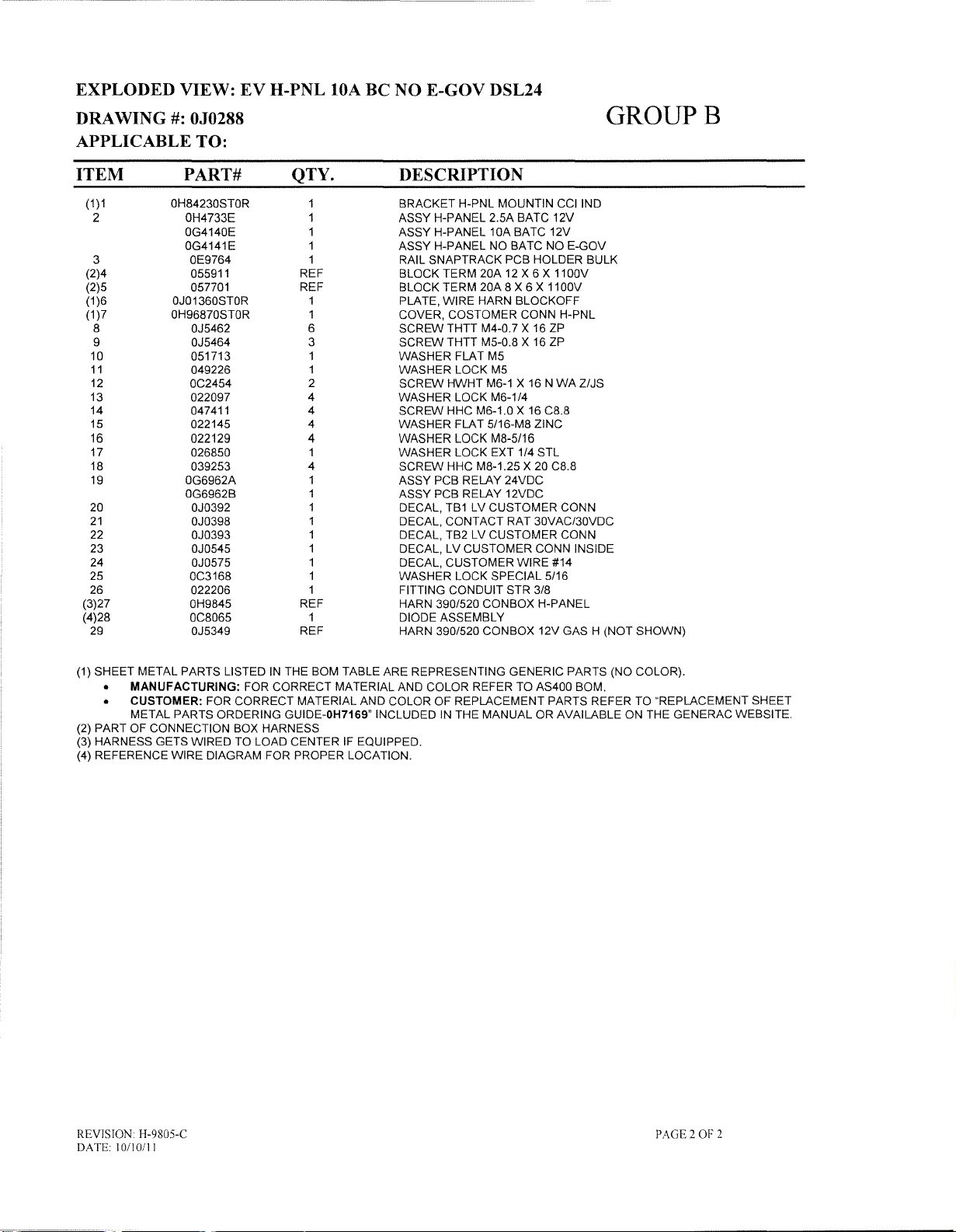
EXPLODED VIEW:
#:
DRAWING
OJ0288
APPLICABLE TO:
EV
H-PNL lOA BC NO E-GOV DSL24
GROUPB
ITEM PART# QTY.
(1)1
2 OH4733E 1 ASSY H-PANEL 2.5A BATC 12V
3 OE9764
(2)4 055911 REF BLOCK TERM 20A
(2)5 057701 REF BLOCK TERM 20A 8 X 6 X
(1
)6 OJ01360STOR 1 PLATE, WIRE HARN BLOCKOFF
(1
)7 OH96870STOR 1 COVER, COSTOMER CONN H-PNL
8 OJ5462 6 SCREW THTT M4-0.7 X 16 ZP
9 OJ5464 3 SCREW THTT M5-0.8 X
10 051713 1 WASHER FLAT M5
11
12
13
14
15 022145 4 WASHER FLAT 5/16-M8 ZINC
16 022129
17
18
19 OG6962A 1 ASSY PCB RELAY 24VDC
20 OJ0392 1 DECAL,
21
22
23 OJ0545 1 DECAL, LV CUSTOMER CONN INSIDE
24 OJ0575 1 DECAL, CUSTOMER WIRE #14
25 OC3168 1 WASHER LOCK SPECIAL 5/16
26
(3)27 OH9845 REF HARN 390/520 CONBOX H-PANEL
(4)28
29 OJ5349 REF HARN 390/520 CONBOX 12V GAS H (NOT SHOWN)
OH84230STOR 1 BRACKET H-PNL MOUNTIN
OG4140E
OG4141E 1 ASSY H-PANEL NO BATC NO E-GOV
049226 1 WASHER LOCK
OC2454
022097
047411
1 ASSY H-PANEL 10A BATC 12V
1 RAIL SNAPTRACK PCB HOLDER BULK
2
4 WASHER LOCK M6-1/4
4
4 WASHER LOCK M8-5/16
026850
039253
OG6962B
OJ0398
OJ0393
022206
OC8065
1 WASHER LOCK EXT 1/4 STL
4 SCREW HHC M8-1.25 X 20 C8.8
1
1
1 DECAL, TB2 LV CUSTOMER CONN
1 FITTING CONDUIT STR 3/8
1
DESCRIPTION
CCIIND
12
X 6 X 1100V
11
OOV
16
ZP
M5
M6-1
SCREW HWHT
SCREW HHC M6-1.0 X 16 C8.8
ASSY PCB RELAY 12VDC
TB1
DECAL, CONTACT RAT 30VAC/30VDC
DIODE ASSEMBLY
X 16 NWAZ/JS
LV CUSTOMER CONN
(1) SHEET METAL PARTS LISTED
• MANUFACTURING: FOR CORRECT MATERIAL AND COLOR REFER TO AS400 BOM.
CUSTOMER: FOR CORRECT MATERIAL AND COLOR OF REPLACEMENT PARTS REFER
METAL PARTS ORDERING GUIDE-OH7169" INCLUDED IN THE MANUAL
(2) PART OF CONNECTION BOX HARNESS
(3) HARNESS GETS WIRED TO LOAD CENTER
(4) REFERENCE WIRE DIAGRAM FOR PROPER LOCATION.
IN
THE BOM TABLE ARE REPRESENTING GENERIC PARTS (NO COLOR).
OR
IF
EQUIPPED.
TO
AVAILABLE ON THE GENERAC WEBSITE.
"REPLACEMENT SHEET
REVISION
DATE
10110111
H-9805-C
PAGE 2
OF
2
Page 34

NOCS
3
4h
~
~
225AF
/'
/'
/'
2
G·FRAME
GROUPH
Revision
Date:
9"
8 •
9hJ~
~"'-J
:
H·9731·C
•
.
6
Page
1 -
~
Exploded
Drawing
View:
No.
EV,CSMOUNTING
:
OJ1027
KIT
MD1
390
Page 35
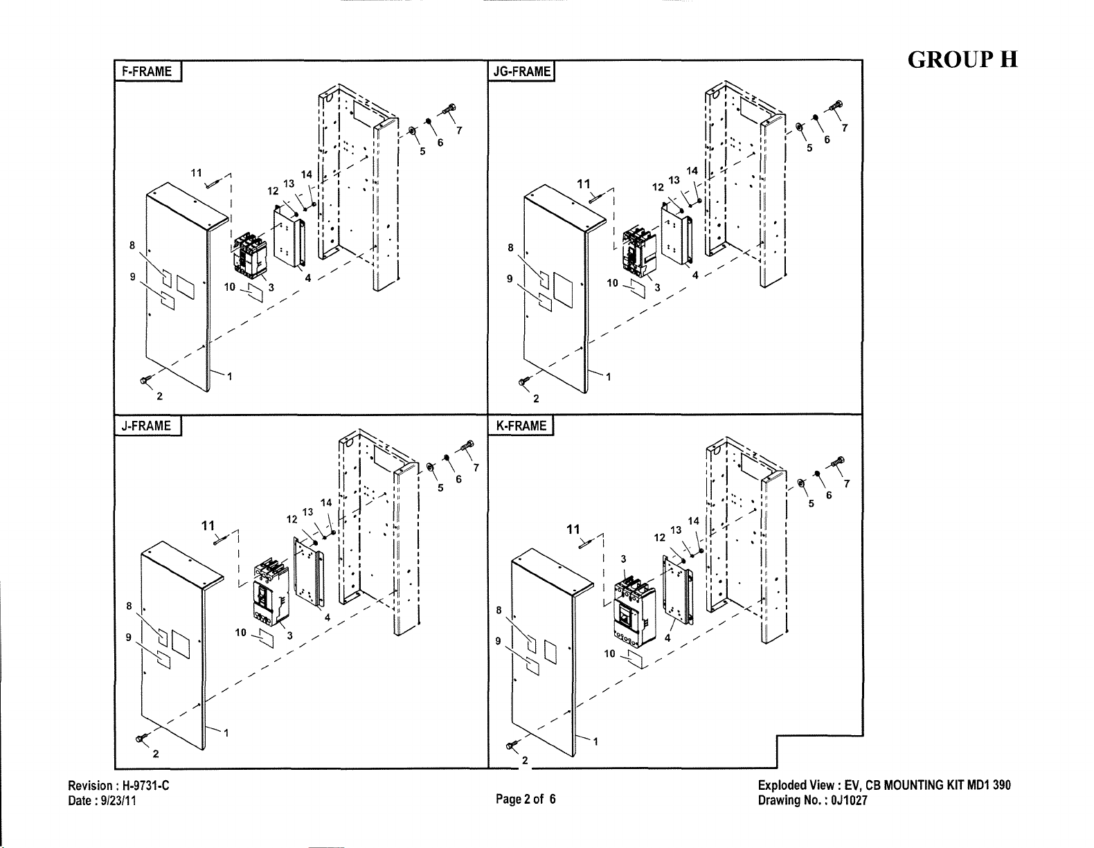
F·FRAME
JG·FRAME
GROUPH
Revision:
Date:
9/23/11
J·FRAME
12
11
y1
I
a:'
~~
8 ,
10
-t::J
3,/'/'/'/
9~tJ·
t:J
~2
L....-
H·9731·C
,/
~,
rrv
::
t'~
"
'I"~~"
",'
~
' I \ 6
II
,"
~"
'1'-:/''"
14 "
,
V
\~"
::'
---J,/
i'
13
,6
~I"
,::
:!':i.
•
~'<11I·1
,/'
4,/
~
'"
I 5
I
'/
II
I
:
:~:
i
/11
I
~j
"i
......
jl
1
III
V
~
..-,
\ 7
K·FRAME
-'--_2
Page2of
~
11
/1
Y I .
I 3
I
~
~
10
~,/
6
1411
12130~
tj,.
'\:,
,/
.l.
. ,
l"-,
,/
•
4
,/
,/
~~
::,
.j"~~
1/
:',
I"
:/~
~.,
','-:
II
'::
11'1
1"1
:!:I'
~<III·I
,/,/,/
• '" , 5
/'
II
~,/
I ·
I
""
"
""
III
'"
~i
,/
'.
'11
~
~
Exploded
Drawing
•
,
I
I
',!
1
\~
6 7
View:
EV,CBMOUNTING
No,
:
OJ1027
KIT
MD1
390
Page 36

GROUPH
L-FRAME
13
12 \ /
"A
~/y
/
~~
t
.:
~
/
d~,
!!~ft::t1
II
:..
:.1
'1'"
1#
14~!!.
~'I'
-1
r"
" :
"I,
:1'1
ri
'.
i.
il;.~
w""
/
/ / / /
,
'
.....
// !
/'<
.
.111
'I"
I~
I"
I
jj
!!
I'"
I '
I"
iii·:
:::
. :
~,
/\"\
(\
I 5
:
I
'I
'I
1
LG-FRAME
6 7
11
y~
8
9~t:J.
~
/
.....
/
/
/
I
I
I
/
/
/
/
Revision:
Date:
91-
H·9731·C
-.
Page3-'
~
2
C
Exploded
Drawing
View:
EV,CBMOUNTING
No.:OJ1027
KIT
MD1
390
Page 37

-----------------------------_
..
_-----------
EXPLODED VIEW: EV, CB MOUNTING KIT
MDl
390
DRAWING#:OJl027
APPLICABLE TO:
ITEM
(1)1
2
3
4
5 OD3719C REF DECAL, HV CUSTOMER CONN INSIDE
(1)6
7
8 022145 4 WASHER FLAT 5/16-M8 ZINC
9 022129 4 WASHER LOCK M8-5/16
10 042907 4
11
12 022241 6 NUT HEX 3/8-16 STEEL
13 022237
14 022131
15 032414 8 SCREW HHC 3/8-16 X 5/8 G5
16 090865 6 STUD 3/8-16 X 1.75 G5 STEEL
(1)1
2
3 REF 1 CIRCUIT BREAKER
(1)4
5 022145 13 WASHER FLAT 5/16-M8 ZINC
6 022129 13 WASHER LOCK M8-5/16
7 042907 4 SCREW HHC M8-1.25 X16C8.8
8
9
10
11
12 038150 4 WASHER FLAT #8 ZINC
13 022264 4 WASHER LOCK #8-M4
14 022471 4 NUT HEX #8-32 STEEL
15 049897 6 SCREW SHC
16 058306 3 SCREW SHC M8-1.25 X 25 C12.9
17
18
19 045771 3 NUT HEX M8-1.25 G8 CLEAR ZINC
20
(1)1
2
3 REF 1 CIRCUIT BREAKER
(1)4
5 022145 4 WASHER FLAT 5/16-M8 ZINC
6 022129 4 WASHER LOCK M8-5/16
7 042907 4 SCREW HHC
8
9
10
11
12 023897 4 WASHER FLAT #10 ZINC
13 022152 4 WASHER LOCK #10
14 022158 4 NUT HEX #10-32 STEEL
15 052647 3 SCREW SHC M10-1.5 X 25 C12.9
16 046526 3 WASHER LOCK M10
17
18 022473 12 WASHER FLAT 1/4-M6 ZINC
19 022097
20 023334
21
PART# QTY.
NO
OH93780STOR
OC2454
OJ0679
OJ0546
OD3719D REF DECAL CUSTOMER CONNE1E3
OJ34710STOR
OJ3958
OC6937M 6 INSULATOR, STANDOFF 600V3/8-16
OH9378ESTOR
OC2454
OJ
14770STOR 1 MD1, C/B MOUNTING BRACKET 225
OJ0679
OJ0546
OD3719C
003719D REF DECAL CUSTOMER CONNE1E3
053640 4 SCREW RHM #8-32 X 3-1/4
OF8451
OF8843
OF8432
OH9378JSTOR 1 M01,MODULE COVER 390 GEN-400
OC2454
OJ00680STOR
OJ0679
OJ0546
OD3719C
OD3719D
069232 4 SCREW
OA7822
OJ7188
CIRCUIT BREAKERS
1 MD1,MODULE COVER 390 G-FRAME
9 SCREW HWHT
1 DECAL, CANADIAN SAFETY CODE
1 DECAL, HV CUSTOMER CONN INSIDE
1 MD1-MD3NOCB MNT BRACKET
REF
12
12
UL CIRCUIT BREAKER (225AF)
1 MD1,MODULE COVER 390 GEN-225
7 SCREW HWHT
1 DECAL, CANADIAN SAFETY CODE
1 DECAL, HV CUSTOMER CONN INSIDE
REF DECAL CUSTOMER CONNE1E2
3
3 BUS BAR 200A
1 INSUL CB 225AF
UL CIRCUIT BREAKER (400AF)
7 SCREW HWHTM6-1 X 16
1 MD2, C/B BACK MOUNTING BRACKET
1 DECAL, CANADIAN SAFETY CODE
1 DECAL, HV CUSTOMER CONN INSIDE
REF DECAL CUSTOMER CONNE1E2
REF DECAL CUSTOMER CONNE1E3
6
12
12
3 BUS BAR ADAPTOR
DESCRIPTION
M6-1
X 16 NWAZ/JS
CU
BUSS BAR 1/4"X2.5" 625A
SCREWHHCM8-1.25X16C8.8
WASHER LOCK 3/8
WASHER FLAT 3/8-M10 ZINC
M6-1
X 16 NWAZ/JS
M8-U5
LUG
SLDLSS 300 MCM-6 AUCU
RHM
LUG
SLOLSS 600/250-1
WASHER LOCK M6-1/4
SCREW HHC 1/4-28 X 1/2 G5
X 20 G8
LUG
ADAPTOR
M8-U5X16
#10-32 X 3-3/4
lOX114-28
NWAZ/JS
C8.8
GROUPH
E3
E3
REVISION H-9731-C
DATE 9/23/11
Page 4of6
Page 38

EXPLODED VIEW: EV, CB MOUNTING KIT
#:
DRAWING
OJI027
APPLICABLE TO:
MDt
390
GROUPH
ITEM
(1)1
2
3 REF 1 CIRCUIT BREAKER
(1)4
5 022145 4 WASHER FLAT 5/16-MS ZINC
6 022129 4 WASHER LOCK MS-5/16
7 042907 4 SCREW HHC MS-1.25 X
S
9
10
11
12
13
14
(1)1
2
3 REF 1 CIRCUIT BREAKER
(1)4
5 022145 4 WASHER FLAT 5/16-MS ZINC
6 022129 4 WASHER LOCK MS-5/16
7 042907 4 SCREW HHC MS-1.25 X
S
9
10
11
12
13
14
(1)1
2
3 REF 1 CIRCUIT BREAKER
(1)4
5 022145 4 WASHER FLAT 5/16-MS ZINC
6 022129 4 WASHER LOCK MS-5/16
7 042907 4 SCREW HHC MS-1.25 X
8
9
10
11
12
13
14
(1)1
2
3
(1)4
5 022145 4 WASHER FLAT 5/16-MS ZINC
6 022129 4 WASHER LOCK MS-5/16
7 042907 4 SCREW HHC MS-1.25 X
S
9
10
11
12
13
14
PART#
UL CIRCUIT BREAKER (G-FRAME)
OH9378ASTOR
OC2454
OJ14SS0STOR
OJ0679
OJ0546
OD3719C
0037190
OJ4465
0431S0 4 WASHER FLAT M4
022264 4 WASHER LOCK #8-M4
051715 4
UL CIRCUIT BREAKER(F-FRAME)
OH937SBSTOR
OC2454
OJ14S60STOR
OJ0679
OJ0546
OD3719C
0037190
OJ4S99
0431S0 4
022264 4 WASHER LOCK #8-M4
051715 4
UL CIRCUIT BREAKER (JG -FRAME)
OH937SDSTOR
OC2454
OJ14S60STOR
OJ0679
OJ0546
OD3719C
OD3719D
OJ4466
0431S0 4 WASHER FLAT
022264 4 WASHER LOCK #S-M4
051715 4 NUT HEX M4-0.7GSYEL CHR
UL CIRCUIT BREAKER
OH9378CSTOR
OC2454
REF
OJ006S0STOR
OJ0679
OJ0546
OD3719C
OD3719D
049967 4
022473 4 WASHER FLAT 1/4-M6 ZINC
022097 4 WASHER LOCK M6-1/4
049S13 4 NUT HEX M6-1.0GSCLEAR ZINC
QTY.
1 MD1,MODULE COVER 390 G-FRAME
7 SCREW HWHT
1 MD1, C/B MOUNTING BRACKETG
1 DECAL, CANADIAN SAFETY CODE
1 DECAL, HV CUSTOMER CONN INSIDE
REF
REF
4 SCREW SHC M4-C.7 XSOC12.9
1
7 SCREW HWHT
1 MD1, C/B MOUNTING BRACKET F
1 DECAL, CANADIAN SAFETY CODE
1 DECAL, HV CUSTOMER CONN INSIDE
REF DECAL CUSTOMER CONNE1E2 E3
REF DECAL CUSTOMER CONNE1E3
4 SCREW SHC M4-0.7 X 45 C12.9
1 MD1,MODULE COVER 390 JG-FRAME
7 SCREW HWHT
1 MD1, C/B MOUNTING BRACKET F
1 DECAL, CANADIAN SAFETY CODE
1 DECAL, HV CUSTOMER CONN INSIDE
REF
REF
4
(J
1 MD1,MODULE COVER 390 J-FRAME
7 SCREW HWHT
1 CIRCUIT BREAKER
1 MD2, C/B BACK MOUNTING BRACKET
1 DECAL, CANADIAN SAFETY CODE
1 DECAL, HV CUSTOMER CONN INSIDE
REF
REF
DESCRIPTION
M6-1
DECAL CUSTOMER CONNE1E2
DECAL CUSTOMER CONNE1E3
NUTHEXM4-0.7GSYELCHR
MD1
,MODULE COVER 390 F-FRAME
WASHERFLATM4
NUTHEXM4-0.7GSYELCHR
DECAL CUSTOMER CONNE1E2
DECAL CUSTOMER CONNE1E3
SCREWSHCM4-C.7X100C12.9
-FRAME)
DECAL CUSTOMER CONNE1E2
DECAL CUSTOMER CONNE1E3
SCREWSHCM6-1.0X70C12.9
M6-1X16
M6-1X16
M4
M6-1X16
X 16 N WAZ/JS
16
CS.S
N WA Z/JS
16
CS.S
N WAZ/JS
16
CS.S
N WAZ/JS
16
CS.S
E3
E3
E3
REVISION
DA
IE
9/231l I
H-973I-C
Page 5of6
Page 39

--------------
EXPLODED VIEW: EV, CB MOUNTING KIT
DRAWING
#:
OJl027
MDl
390
APPLICABLE TO:
ITEM
(1)1
2
3 REF 1 CIRCUIT BREAKER
(1)4 OJ00680STOR 1 MD2, CIB BACK MOUNTING BRACKET
5 022145 4 WASHER FLAT
6 022129 4 WASHER LOCK
7 042907 4 SCREW HHC M8-1.25 X16C8.8
8
9
10 OD3719C REF DECAL CUSTOMER CONNE1E2
11
12 022473 4 WASHER FLAT
13 022097 4 WASHER LOCK
14 049813 4 NUT HEX M6-1.0 G8 CLEAR ZINC
(1)1
2
3 REF 1 CIRCUIT BREAKER
(1)4 OJ00680STOR 1 MD2, CIB BACK MOUNTING BRACKET
5 022145 4 WASHER FLAT
6 022129 4 WASHER LOCK
7 042907 4 SCREW HHC M8-1.25 X16C8.8
8
9
10 OD3719C REF DECAL CUSTOMER CONNE1E2
11
12 022473 4 WASHER FLAT
13 022097 4 WASHER LOCK
14 049813 4 NUT HEX M6-1.0 G8 CLEAR ZINC
PART#
UL CIRCUIT BREAKER(K-FRAME)
OH9378FSTOR 1 MD1,MODULE COVER 390 K-FRAME
OC2454
OJ0679
OJ0546
OD3719D REF DECAL CUSTOMER CONNE1E3
046580 4 SCREW SHC M6-1.0 X 45 C12.9
UL CIRCUIT BREAKER (L -FRAME)
OH9378GSTOR 1 MD1,MODULE COVER 390 L-FRAME
OC2454
OJ0679
OJ0546
OD3719D REF DECAL CUSTOMER CONNE1E3
046580 4 SCREW SHC M6-1.0 X 45 C12.9
QTY.
7 SCREW HWHT
1 DECAL, CANADIAN SAFETY CODE
1 DECAL, HV CUSTOMER CONN INSIDE
7 SCREW HWHT
1 DECAL, CANADIAN SAFETY CODE
1 DECAL, HV CUSTOMER CONN INSIDE
DESCRIPTION
M6-1
5116-M8
M8-5116
114-M6
M6-114
M6-1
5116-M8
M8-5116
114-M6
M6-114
X 16 NWAZIJS
ZINC
ZINC
X 16 NWAZIJS
ZINC
ZINC
GROUPH
E3
E3
(1)1
2
3 REF 1 CIRCUIT BREAKER
(1)4 OJ00680STOR 1 MD2, CIB BACK MOUNTING BRACKET
5 022145 4 WASHER FLAT
6 022129 4 WASHER LOCK
7 042907 4 SCREW HHC M8-1.25 X16C8.8
8
9
10 OD3719C REF DECAL CUSTOMER CONNE1E2
11
12 051713 4 WASHER FLAT
13 049226 4 WASHER LOCK
14 051716 4 NUT HEX M5-0.8 G8 CLEAR ZINC
NOTES (UNLESS OTHERWISE SPECIFEID):
(1) SHEET METAL PARTS LISTEDINTHE BOM TABLE ARE REPRESENTING GENERIC PARTS
MANUFACTURING: FOR CORRECT MATERIAL AND COLOR REFER TO AS400 BOM.
CUSTOMER: WHEN ORDERING REPLACEMENT PARTS ENTER BASE NUMBER (FIRST 6 DIGITS ONLY)INTHE
SYSTEM FOR CORRECT MATERIAL AND COLOR (FOR REFERENCE SEE GUIDELINE OH7169).
UL CIRCUIT BREAKER (LG-FRAME)
OH9378HSTOR
OC2454
OJ0679
OJ0546
OD3719D REF DECAL CUSTOMER CONNE1E3
OJ4467
1 MD1,MODULE COVER 390 LG-FRAME
7 SCREW HWHT
1 DECAL, CANADIAN SAFETY CODE
1 DECAL, HV CUSTOMER CONN INSIDE
4
SCREWSHCM5-0.8X100C12.9
M6-1
5116-M8
M8-5116
M5
M5
X 16
ZINC
NWAZIJS
E3
(NO
COLOR)
REVISION H-9731-C
DATE
9123/11
Page 6of6
Page 40

GROUP
11
A
1
2
Page1."
Exploded
Drawing
View'
EV
No.:
Oj133;ONBOX
390
MODULE
Page 41

----
--
---~-----
EXPLODED VIEW:
DRAWING#:
OJ1339
EV
CONBOX 390 MODULE
APPLICABLE TO:
ITEM
(1)1
(1)2
3 0A4456
4 061383
5 OE1534A
6 056326
7 045772
8
9 OH8006 1 DECAL CAUTION ELEC SHOCK
10 OA9457 1 DECAL NEUTRAL
11
12 024526
13 022129 4 WASHER LOCK M8-5/16
14 022145
15 0441140781
16
17 049541
(3)(2)18
(3)(2)19
(3)(2)20
(3)(2)21
22
23 067210A
PART#
OH95790STOR
OJ
17560STOR
067210A
OC2454
022131 4 WASHER FLAT 3/8-M10 ZINC
OJ0455 REF BLOCK, TERM 14 POS X 8 X 1600V
OJ0394 REF DECAL, TB4 HV CUSTOMER CONN
OJ0574 REF DECAL, CUSTOMER WIRE #10
OJ5462 REF SCREW THTT M4-0.7 X
061383 1 LUG SLDLSS 3/0-#4 X 13/32
QTY.
1
1 WIRE TUNNEL, MD1-2 390 ALT
3 WASHER LOCK SPECIAL 3/8
1
2
2
1
1 DECAL GROUND LUG
4
4
4 WASHER FLAT 5/16-M8 ZINC
1
2 SCREW HHC M10-1.5 X
1 DECAL GROUND LUG
DESCRIPTION
MD1
/ MD2 CB MODULE 390 ALT
LUG SLDLSS 3/0-#4 X 13/32 CU
PLUG PLASTIC 1.50"
TRIM VINYL BLACK 1/8GP (7.1"LG)
NUTHEXM1~1.5G8YELCHR
SCREW HWHT
SCREW HHTT 5/16-18 X 3/4 CZ
WIRE ASM, GND 2/0 WIRE 3/8 LUG
M6-1
X 16 NWAZ/JS
GROUP A
SM
35
C8.8
16
ZP
CU
(1) SHEET METAL PARTS LISTEDINTHE BOM TABLE ARE REPRESENTING GENERIC PARTS (NO COLOR).
• MANUFACTURING: FOR CORRECT MATERIAL AND COLOR REFER
CUSTOMER: FOR CORRECT MATERIAL AND COLOR OF REPLACEMENT PARTS REFER TO "REPLACEMENT SHEET
METAL PARTS ORDERING GUIDE-OH7169" INCLUDEDINTHE MANUALORAVAILABLE ON THE GENERAC WEBSITE.
(2) WILL BE INSTALLED ON PRIMARY CB MODULES ONLY. NOT REQUIRED WITH LOAD CENTER.
(3) NOT REQUIRED IF EQUIPPED WITH LOAD CENTER.
TO
AS400 BOM.
REVISION
DATE
II/2IIlI
J-I088-C
PAGE 2OF2
Page 42

TO
fLYWHEEL
~
24
"-
I
I
I
I
I
I
I
I
I
l
,
,
,
,
,
,
,
,
7
,
,
,
,
,
,
,
,
,
,
12
,
,
,
GROUP
A
'I
I
I
I
I
,
,
,
,,-,
20
,
,~~
'/~J),,~
~,
~
/'/rY
',~r',:<
,
, , J
I
, '
l ':
'~
':''k''
"
~.:.:.?"
'l..
-'
:ij
,,~
~
~~
>
,
,
6
~
I
I
,
2&3)
/.:23
-./
I
I
I
I
I
I
I
I
n
I
I
I
67
I
I
I
)
-'
-'
SCROLL
DETAIL
"A"
Page
1-'•
Exploded
Drawing
View:EVALTCOMPRT
No.
:
OJ1481
<80KWDDPME
G17
Page 43

EXPLODED VIEW:
EV
ALTCOMPRT <80KW DD PME G17
DRAWING
#:
OJ1481
APPLICABLE TO:
ITEM PART#
1
2 051769
3 PIN VARIES
4 055173
5 022129
6 037554C
7 OG0724
8
9 OA2602
10 OA1138
11
12
13 OA1786
14
15 OA1633
16
17 022131
18 046526
19
20 097485
21
22
23 051779
24
25 080934
26 022473
27 022097
28 082460
29
30 084828B
31
32
33
34
35
36 087271
37 OG2829
38
39
40 046526
41
42 022145 6
43 OH7393
44
46 089520 2
51
54 090152
55 0A4089
56 OE9107
57 023365 2
063837
OA2601
021941
VARIES
OA5580
VARIES
057642
OH8394
043123
094511
OH7626
088367
042558
OH7625A
OH7625C
OA2110
OE8771
OE8782
087272
OA1138
04576100CN
022131 8
045772
OF1965
043180 2
QTY.
6 SCREW HHC M12-1.75 X 30 C10.9
6 WASHER LOCK M12
REF
6 SCREW HHC M8-1.25 X
6 WASHER LOCK
1 SLEEVING UL #2
1 FAN MACHINED 390 SAE AL TERATOR
1 SCREW HHC M16-2 X 45 G8.8
1 WASHER FLAT .6881D X 3.25
1 KEY SO
1 COUPLER 390 SAE
REF ROTOR PER ORDER (SEE BOM)
.5CC ADH LOCTITE #8931 AA
4 SCREW HHC M14-2.0 X 140 G8.8
4 WASHER 390 SAE ALT.
REF STATOR PER ORDER (SEE BOM)
18 WASHER FLAT
12 WASHER LOCK M10
12
1 BEARING CARRIER 390 PMG REAR
1
4 WASHER LOCK M14
4 NUT HEX M14-2
1 ASSY STATOR PME
1 RING PME STATOR RETAINING
4 WASHER FLAT
4 WASHER LOCK
4
1
1 HOUSING 520 PME MAGNET
1
1 KEY SO
1 COLLAR SLIP FIT 71.12
1
2
1 EXCITER FIELD 1.25" WICAN 25KW-35KW
1 EXCITER FIELD 2.00" 40KW-125KW
1 ASSEMBLY EXCITER 25KW-35KW
1 ASSEMBLY EXCITER 40KW-125KW
1 KEY SO
1 KEY SO 3/8 X
4
8 WASHER LOCK M10
8 NUT HEX M10-1.5
1 M20 RIBBED LOCKWASHER
1
1 ASSEMBLY BRIDGE RECTIFIER
1 ASSEMBLY SCROLL 390 SAE
1 MOUNT RECTIFIER
DESCRIPTION
FLEX PLATE
3/8 X
2-1/2
M10-3/8
SCREW HHC M10-1.5 X 40 G8.8
390. BOARD SOLID LEAD TERM PME
M6-1/4
SCREW SHC M6-1.0 X 65 G10.9
COLLAR SLIP FIT 122.65MM
FAN MAGNETIC HOUSING
COLLAR SLIP FIT 90.17
SCREW SWAGE
STUD M10-1.5 X 280 G5 ZINC
WASHER FLAT
WASHER FLAT
SCREW HHC M20-1.5 X 55 C8.8
SCREW PFILHM M4-0.7 X
WASHER FLAT M4
WASHER SHAKEPROOF INT #8
3/8 X 1 STEEL
3/8 X 1-3/4 STEEL
2-1/2
M8-5/16
.2681D
STEEL
M6-1/4
1/4-20
STEEL
M10-3/8
5/16-M8
20
G10.9
3"PRECUT
WIS
ZINC
ZINC
X 1/2
lYC
ZINC
ZINC
16
OD
GROUP A
REVISION H-9012-C
DATE
5/20111
Page 2of4
Page 44

EXPLODED VIEW:
#:
DRAWING
OJ1481
APPLICABLE TO:
EV
ALTCOMPRT <80KW DD PME G17
GROUP A
ITEM
60
61
62 OA2496
63
64 022097 6
65
66
67 047411
68
PART#
KIT 0A4089 PARTS
OA2491
OA2497
056326 8.4 FT
022473 6
OA2110
045757
QTY.
2
2 SCREEN SHROUD SAE
2 BRACKET TENSIONER SAE SCROLL
12 SCREW SWAGE
4
2
DESCRIPTION
SHROUD ALT SHEET METAL
TRIM VINYL BLACK
WASHER LOCK
WASHER FLAT
SCREW HHC M6-1,O X 16 G8,8
SCREW HHC M6-1,O X 25 G8,8
1/8 GP
M6-1/4
1/4-M6 ZINC
1/4-20 X 1/2 ZlYC
REVISION H-9012-C
DATE
5/20/11
Page 3of4
Page 45

EXPLODED VIEW:
EV
ALTCOMPRT <80KW DD PME G17
#:
DRAWING
OJ1481
APPLICABLE TO:
THIS PAGE LEFT INTENTIONALLY BLANK
GROUP A
REVISION H-9012-C
DATE 5/20/11
Page 4
of
4
Page 46

20
GROUP
A
y--11
I
2
DUAL
MODULE
OPTION
Revl
Date:
's'lon'
71'
H-9332-C
"
3
,
w'
EV
Exploded
DrawingNo..
Vie,
ALT-TOWER
Oj1584
SPC
PRT
390
ALT
Page 47

EXPLODED VIEW:
EV
390 ALTERNATOR
TOWER
ASM
DRAWING
#:
OJ1584
APPLICABLE TO:
ITEM
(1
)1
(1)2
(1)2A
(1)3
(3)4
5
(1)6
7
8
9
(2)10
11
(3)12
(3)13
14
15
16
(3)17
18
19
20
PART#
OH9429ASTOR
OH94310STOR
OH9431ASTOR
OH94320STOR
OJ0481
OJ0481A
OJ0481B
OJ0481C
OJ0481D
OJ0481
OJ0481
OJ0481G
NIA
OJ01360STOR
OJ5464
022097
022473
056326
OC2454
022145
022129
042907
045771
024983
OJ1857
OJ1857A
OC1229
OH9845
052250
GROUP A
QTY.
1
1
1
1
2/3
2/3
2/3
2/3
2/3
E
F
2/3
2/3
2/3
1
2
4
4
2/4
12
4/8
2/3
2/3
2/3
4
2/3
2/3
1
1
1
DESCRIPTION
MAIN, ALT TOWER 390 LONG
TOP, AL T TOWER 390 SINGLE CB
TOP, ALT TOWER 390 DUAL CB
COVER,
XFMR CURRENT 50A W/BRKT UL RCG
XFMR CURRENT 100A W/BRKT UL G
XFMR CURRENT 150A W/BRKT UL
XFMR CURRENT 200A W/BRKT UL
XFMR CURRENT 300A W/BRKT UL
XFMR CURRENT 400AW/BRKT UL
XFMR CURRENT 500AW/BRKT UL
XFMR CURRENT 600A W/BRKTUL
PLATE, WIRE HARN BLOCKOFF
SCREW
WASHER LOCK M6-1/4
WASHER FLAT 1/4-M6 ZINC
TRIM VINYL BLACK 1/8GP (6"LG)
SCREW HWHT M6-1 X 16 NWAZ/JS
WASHER FLAT 5/16-M8 ZINC
WASHER LOCK M8-5/16
SCREW HHC M8-1.25 X 16 C8.8
NUT HEX M8-1.25 G8 CLEAR ZINC
SCREW HHTT 1/4-20 X 3/4 CZ
CTBRKT
CT BRKT 2.25"
DECAL WARNING ELECTRICAL SHOCK
HARN 390/520 CON BOX H-PANEL (NOT SHOWN)
TAPE FOAM
AL
T TOWER 390
THTT
M5-0.8 X 16 ZP
1.1"WINDOWFRAME
WINDOW
1X1
FRAME
(49" LG)
NOTES (UNLESS OTHERWISE SPECIFIED):
(1) SHEET METAL PARTS LISTED
• MANUFACTURING: FOR CORRECT MATERIAL AND COLOR REFER TO AS400 BOM.
CUSTOMER: WHEN ORDERING REPLACEMENT PARTS ENTER BASE NUMBER (FIRST 6 DIGITS ONLY) IN THE
SYSTEM FOR CORRECT MATERIAL AND COLOR (FOR REFERENCE SEE GUIDELINE OH7169).
(3) QTY. REQUIRED FOR 1 PHASE
IN
THE BOM TABLE ARE REPRESENTING GENERIC PARTS (NO COLOR)
1QTY. REQUIRED FOR 3 PHASE.
REVISION
DATE
7/19/11
H-9332-C
PAGE20F2
Page 48

GROUP
4
3
;./
A
'v
'1
7
I "
~<11
10
12
390
ALTERNATOR
SINGLE
CIS
Revision:
Date:
9'- •
H·9670·B
4
3 V
Y
520
ALTERNATOR
SINGLE
CIS
Page
1' •
390/520
~
ALTERNATOR
Exploded
Drawing
DUAL
View:
No.
:
CIS
EV,
OJ5190
LOAD
CENTER
KIT
390/520
Page 49

EXPLODED VIEW: EV, LOAD CENTER KIT 390/520
DRAWING
#:
OJ5190
APPLICABLE TO:
ITEM
(1)2
3 039253 4 SCREW HHC M8-1.25 X 20 CB.B
4 022145 8 WASHER FLAT 5/16-MB ZINC
5 022129 4 WASHER LOCK MB-5/16
6 045771 4 NUT HEX MB-1.25GBCLEAR ZINC
7
8
9 036920 2 SCREW PPHM #B-32 X 3/4
10 03B150 2 WASHER FLAT #8 ZINC
11
12 022471 2 NUT HEX #B-32 STEEL
13
2
3 039253 4 SCREW HHC M8-1.25 X 20 CB.B
4 022145 8 WASHER FLAT 5/16-MB ZINC
5 022129 4 WASHER LOCK MB-5/16
6 045771 4 NUT HEX MB-1.25 G8 CLEAR ZINC
7
8 036920 2 SCREW PPHM #B-32 X 3/4
9 03B150 2 WASHER FLAT
10 022264 2 WASHER LOCK #B-M4
11
PART#
390 ALTERNATOR SINGLE C/B
OD8602
OD8602A 1 LOAD CTR, 125A,SIEMENS NEMA
OJ51820STOR
OC2454
OE6523
022264 2 WASHER LOCK #8-M4
OF1735
520 ALTERNATOR SINGLE C/B
ODB602
ODB602A
OF1735
OE6523
022471 2 NUT HEX #B-32 STEEL
QTY.
1 LOAD CENTER,125A,SIEMENS 8 BAY\
1 390 ALT LOAD CENTER MOUNT
2 SCREW HWHT
1 GROUND BAR (5)4-14 AWG CONN
1 DECAL AUXILIARY LOAD PANEL
1 LOAD CENTER,125A,SIEMENS B BAY
1 LOAD CTR, 125A,SIEMENS NEMA
1 DECAL AUXILIARY LOAD PANEL
1 GROUND BAR (5)4-14 AWG CONN
DESCRIPTION
M6-1
#B
X 16 NWAZ/JS
ZINC
GROUP A
3R
3R
390/520 ALTERNATOR DUAL C/B
ODB602
(1)2
3 039253 4 SCREW HHC M8-1.25 X
4 022145 8 WASHER FLAT 5/16-MB ZINC
5 022129 4 WASHER LOCK MB-5/16
6 045771 4 NUT HEX M8-1.25GBCLEAR ZINC
7
8 036920 2 SCREW PPHM #8-32 X 'l:;
9 038150 2 WASHER FLAT#BZINC
10 022264 2 WASHER LOCK #8-M4
11
12
NOTES (UNLESS OTHERWISE SPECIFEID):
(1)
SHEET METAL PARTS LISTEDINTHE BOM TABLE ARE REPRESENTING GENERIC PARTS (NO COLOR)
• MANUFACTURING: FOR CORRECT MATERIAL AND COLOR REFER TO AS400 BOM.
CUSTOMER: WHEN ORDERING REPLACEMENT PARTS ENTER BASE NUMBER (FIRST 6 DIGITS ONLY)INTHE
SYSTEM FOR CORRECT MATERIAL AND COLOR (FOR REFERENCE SEE GUIDELINE OH7169).
ODB602A
OJ27960STOR
OE6523
022471 2 NUT HEX #B-32 STEEL
OF1735
1 LOAD CENTER,125A,SIEMENS 8 BAY
1 LOAD CTR, 125A,SIEMENS NEMA
2 BRACKET, LOAD CENTER DUAL MOD
20
1 GROUND BAR (5)4-14 AWG CONN
1 DECAL AUXILIARY LOAD PANEL
3R
CB.B
REVISION H-9670-B
DATE
9/13/11
Page 2of2
Page 50

EXPLODED VIEW:
DRAWING
APPLICABLE TO:
VOLTAGE
120/240 1$
120/2083$
#:
OF9280
OPE
FREQUENCY
60 Hz
60 Hz
TABLE
H-100
Breaker
EX
PME/brushless
PME/brushless
FIELD
and Field
direct
RES&OPE
Boost
Resistor
390
mm
smaller
390 mm or
smaller
CB
GROUP B
Table
for
Gensets
or
with
H-Panel
Control
& 12V Battery
FIELD BOOST RESISTOR
PART NO. SIZE
OF5752E 5 ohm
OF5752B
OF5752E
OF5752B
25 ohm
7
5 ohm
25 ohm
120/2403$
277/4803$
346/6003$
110/220 1$
100/2003$
60 Hz
60 Hz
60 Hz
50 Hz
50 Hz
direct
PME/brushless
direct
PME/brushless
direct
PME/brushless
direct
PME/brushless
direct
PME/brushless
390
mm
smaller
390 mm or
smaller
390 mm or
smaller
390
mm
smaller
390
mm
smaller
7
20
OF5752E
or
OF5752B
OF5752E
OF5752B
OF5752E
OF5752B
or
OF5752B
OF5752E
or
OF5752B
7 h
5 ohm
25 ohm
5 ohm
25 ohm
7
5 ohm
25 ohm
25 ohm
5 ohm
25 ohm
115/200
231/4003$
REVISION:
10131105
DATE:
3$
50 Hz
50 Hz
direct
PME/brushless
direct
PME/brushless
390 mm or
smaller
390 mm or
smaller
mm
OF5752E
OF5752B
OF5752E
OF5752B
20
PAGE 1 OF 2
5 ohm
25 ohm
50hm
25 ohm
7 hm
Page 51

EXPLODED VIEW:
DRAWING #:
APPLICABLE TO:
OF9280
TABLE
H-100
FIELD
RES&DPE
CB
GROUP B
BLANK
PAGE
REVISION:
DATE: 10/31/05
PAGE20F2
Page 52

OIL
PIN
TEMP
KIT
OH5427
f',.
27
1 '
7,
fTO"A"
:~12
:
~6
25
Vy
1
~
1
Y
29
9
GROUPB
USE
EXISTING
28
30
¥
(2)NOTE:
ALTERNATOR
ENGINE
33
)I
16
34
~
THRU
520
TO
Revision:
Date:
7/""
17;1\\"
HARNESS
GROUND
5033'-.
Y
H·9325·
D
7
8
e 1 19
~
49
17
~
~..--
~"--~h
~
18 19
,
1
20
143
Y
) ,
20'''--''--
\/
V..--.-
6
<..
10'
,-
';:;.>
JtIJ
'~
.....
, 1
~
3
4
Page
16
,.j
~
_..;;;::--.\V
1" •
31
Exploded
Drawing
View'
No.:
ENG
OH2124
COM
PARTS
6.7LLOG17
Page 53

EXPLODED VIEW:
EV
ENGCOMPRT 6.7L LO G17
DRAWING
#:
OH2124
APPLICABLE TO:
ITEM
1
(2)2
3
4
5
6
7
8
(2)9
(4)10
(3)11
12
(5)13
(5014
15
16
17
18
19
20
21
22
23
24
25
26
27
28
29
30
31
32
33
(2)34
(1)35
36
37
38
39
40
(5)41
42
43
44
45
46
47
(2)48
49
PART#
OJ2730
021322A
(1) 020604
OH2119A
OF2610
OH21450ST03
OH21460ST03
OH3201
OH22980ST03
021325
055934P
055934M
OH5182A
OH51420SS0R
OH51410SS0R
051756
046526
081816
063837
051769
049808
OD2244M
OH5002
045757
022097
022473
043116
052857
022129
022145
042907
090502
OJ4574
022131
052647
057642
OA4707A
052648
OF4612
030418
OE0502
OH61800SS0R
OF2776
051768
039253
055934B
086292
OH4195
045773
025507
QTY.
REF
5
3
1
1
1
1
1
2
1
1
1
1
1
1
4
27
16
10
34
43
1
1
1
1
2
1
1
5
5
4
4
8
21
12
12
1
4
1
1
1
1
1
7
2
1
1
1
12
1
GROUPB
DESCRIPTION
ENGINE D6.7L G17 100/130KW
FLEX PLATE,
PLATE FLEX
FAN SPACER 6.7L G17
FAN COOL 26"
FOOT ENGINELFD6.7L G17
FOOT ENGINE
ENGINE FOOT SPACER
REAR ENGINE FEET 4.5L G17
ADAPTER SAE3X520 ALT (MACHO)
CLAMP
CLAMP
ASSY. MECH BOSCH ACTUATOR
HEAT SHEILD TURBO 6.7L
HEAT SHEILD 6.7L 100-130KWG17
SCREW HHC M10-1.5X 20 C8.8
WASHER LOCK M10
SCREW HHC M12-1.75 X 55 C10.9
SCREW HHC M12-1.75 X 30 C10.9
WASHER LOCK M12
WASHER FLAT M12
ASSY MAGPICKUP(3/8-24 MALE)
ADAPTER MAG PICKUP 6.7L
SCREW HHC M6-1.0 X 25 C8.8
WASHER LOCK
WASHER FLAT
SCREW HHC M6-1.0 X
NUT TOP LOCK FL M6-1.0
WASHER LOCK
WASHER FLAT
SCREW HHC M8-1.25 X16C8.8
SCREW SHC M10-1.5 X 60 C12.9
SCREW
WASHER FLAT
SCREW SHC M10-1.5 X 25 C12.9
SCREW HHC M10-1.5 X 40 C8.8
ADPATER 1/8NPT X M10-1.0
SCREW SHC M10-1.5 X 20 C12.9
SENDER OIL PRESSURE 1/8"NPT
BSHG RDCR HEX
TEMPERATURE SENDER, DELPHI
HEAT SHEILD 6.7LG17
BRACKET, SIGNAL CONDITIONER
SCREW HHC M12-1.75 X 25 C8.8
SCREW HHC M8-1.25 X 20 C8.8
CLAMP
SCREW HWHSD #10-16 X
HARN ENG D4.5L1D6.7L G17 H-PNL (NOT SHOWN)
NUT HEX M12-1.75 G8 YEL CHR
WASHER LOCK EXT
STLNNL
STLNNL
SHC
M10-1.5X25
STLNNL
520ALT
11-112
LH
RF
1.62 X .486
.75 X .343 Z
M6-1/4
1/4-M6
M8-5/16
5/16-M8
3/8-M10
1 X
SAE 390
ROTATION
D6.7L G17
ZINC
12
G8.8
ZINC
C8.8
ZINC
1/2 TO 3/8
100/130
.281
Z (NOT SHOWN)
3/4
7/16
STL
LO
G17
LO
G17
LH
SEMS (NOT SHOWN)
REVISION H-9325-0
DATE
7/27//11
Page 2of4
Page 54

EXPLODED VIEW:
EV
ENGCOMPRT 6.7L LO G
17
DRAWING
#:
OH2124
APPLICABLE TO:
ITEM
50
51
A
B
C
D
E
F
G
(1) W
1390
(2) W I 520 ALTERNATOR ONLY
(3) FOR ENGINE HARNESS
(4) FOR BLOCK HEATER
(5) SHEET METAL PARTS LISTED
• MANUFACTURING: FOR CORRECT MATERIAL AND COLOR REFER TO AS400 BOM.
• CUSTOMER: FOR CORRECT MATERIAL AND COLOR OF REPLACEMENT PARTS REFER
METAL PARTS ORDERING GUIDE-OH7169" INCLUDEDINTHE MANUAL OR AVAILABLE ON THE GENERAC WEBSITE.
PART#
049814
055934M 1
OIL TEMP KIT PIN OH5427
OA4707L 1
OE0502 1
OF2776A 1
022145 1
022129 1
042907 1
OG0349 1
ALTERNATOR ONLY
QTY.
IN
THE BOM TABLE ARE REPRESENTING GENERIC PARTS (NO COLOR).
DESCRIPTION
SCREW HHC M10-1.5 X 25 C8.8
STLNNL
CLAMP
ADAPTER 3/8NPT
TEMPERATURE SENDER, DELPHI
BRACKET, SIGNAL CONDITIONER
WASHER FLAT
WASHER LOCK
SCREW HHC M8-1.25 X16C8.8
HARN OIL TEMP SENDER OPTION
.75 X .343 Z
X M14-1.5
5/16-M8
M8-5/16
ZINC
GROUPB
TO
"REPLACEMENT SHEET
REVISION H-9325-D
DATE
7/271/1
I
Page 3of4
Page 55

EXPLODED VIEW:
EV
ENGCOMPRT
6.7L
LO
G17
DRAWING
#:
OH2124
APPLICABLE TO:
THIS PAGE LEFT INTENTIONALLY BLANK
GROUPB
REVISION H-9325-D
DATE
7/27//11
Page 4of4
Page 56

GROUP B
NOTE1:ITEM29ATTACHESTOCONTACTONREAROfITEM
REVISION:
DATE: IZIZt
J-1
"""-D
5
PAG!
EXPLODED
H-PANEL
2
DRA
10A
WINO
VIEW:
BATIERY
#:
OH5043D
CHARGER
E-GOV
DSL
12V
Page 57

EXPLODED VIEW:
DRAWING #:
APPLICABLE TO:
OH5043D
H-PANEL
10A
BATIERY
CHARGER
E-GOV
DIESEL
12V
GROUP B
ITEM
10
11
12
13
14
15
16
17
18
19
20
21
22
23
24
25
26
27
28
29
A
B
C
D
E
1
2
3
4
5
6
7
8
9
PART#
OF1823CST03
OF
1824AST03
OF2606
036261
OF5763
OF1732
OE9764
OF1740C
OF1958
OF2256
OE3161
029673
049226
079224
051713
OF5886
051716
043180
OC3990
OF4333
OF5883
OF5884
055014
022264
003546
OG3648
OF6305
OF6305A
OG4329
OF1263
OF1262
OF1264
OE9049B
055911
9BieQN~J
ENCL
H/G
1
1
1
7
1
1
1
FT.
1
1
1
1
1
11
4
11
6
5
3
3
1
1
1
10
10
1
1
1
1
1
COMPONENTS
1
4
1
1
1
CONTROL
COVER
CONTROL
HINGE
CONTINUOUS
RIVET
POP
ASSY
DECAL
RAIL
ASSY
PLATE
ASSYPCB
ASSY
DIO
WASHER
SCREW
WASHER
SCREW
NUT
WASHER
SCREW
CONN
WASHER
SCREW
SCREW
WASHER
DECAL
M5-0.8
SEAL
SEAL
HARNESS
ADPTRRHSIDE
HOLDER
ADPTRLHSIDE
ASSY
BLOCK
.125X.275
PROGRAMMED
FUSES
SNAPTRACK
PCB
10AULBAn
HARNESS
PWR
PCB
BOSCH
BRIDGE
LOCK
PPHM
FLAT
HHPM
HEX
Ms-D.8G8YEL
FLAT
PHTT
DUST
FLAT
PHTT
PPHM
LOCK
WRN
CAPTIVE
COVER
COVER
H·PNL
INCLUDEDINWIRE
FUSE
PCB
G·PANEL
TERM
0G'14QE
PANEL
PANEL
H·PANEL
SS
H·100
LOCATED
INSIDE
PCB
HOLDER
CHRGR
CLAMP
AVRW/AMP
GOV
25A
CAP
DRIVER
600V
M5
M5-0.8X30
Ms-D.8X12
M4-0.7X10
M3.5-0.6X10
M4-0.7X8BLK
BATT
3.18X12.7X382
3.18X12.7X283
20A12X6X
SS
M5
CHR
M4
rYC
WICHAIN
M3.5
WICKMANN
DB9
#8·M4
CHRG
12124V
PANEL
KNLD
INTEGRATEDSW(NOT
HARNESS
WICKMANN
178.6150
WICKMANN
RELAY
1100V
BULK
12V
HEADER
OX
BI
HD
178.6191
178.6192
12VDC
SHOWN)
ITEM
50
51
52
53
54
55
56
57
58
59
60
61
62
63
64
65
66
67
68
PART
056739
022287
022473
022097
022127
043182
051714
052777
OC2323
OC2699
OE7403B
OE7403C
OJ7646
OF5461
OF5752A
OF6145
OF7473
1
RELAY
2
4
2
2
REF.
REF.
4
4
4
2
2
1
1
1
1
1
AIR
1
CONTACTOR
SCREW
HHC
WASHER
FLAT
WASHER
LOCK
NUT
HEX
1/4-20
DPE
BREAKER
BOOST
RESISTOR
WASHER
LOCK
NUT
HEX
M3·0.5G8YEL
WASHER
FLAT
SCREW
PHn
SCREW
PHTT
FUSEATO
TYPE10AMP
FUSE
ATO
TYPE15AMP
DECAL
CONTROL
DECAL
CPL
RESWW10R5%15WOKCONN
SEAL
WEATHER
DECAL
H·100
12VDC
1/4·20X3/4
M6
·1/4
M6·
1/4
STEEL
SEE
DRAWING
SEE
M3
M3
#6-32
X5/8rYC
#6-32
X3/8rYC
BOX
5.416.8L
TB3
AS'
DIA
RELAYBD12V
G5
OF9280
DRAWING
CHR
(RED)
(BLUE)
FUSES
RB1
OF9280
REVISION: J-I00I-D
DATE:
12/2/11
PAGE20F2
Page 58

GROUP H
Revision:
Date:
zr
H·6096·C
Page1--
Exploded
Drawing
View:
No.:
KIT
FAN
OG4310
GUARD
Page 59

GROUP B
NOTE1:ITEM29ATTACHESTOCONTACTONREAROFITEM
REVISION: J-IOOI-D
DATE: 12/2/II
SEE
DETAIL
"A"
5
PAGE 1
OF2
EXPLODED
H-PANEL
10A
DRAWING
VIEW:
BATIERY
#:
OH5043D
CHARGER
E-GOV
DSL
12V
Page 60

EXPLODED VIEW:
DRAWING
APPLICABLE TO:
ITEM
1
OF1823CST03
2
OF1824AST03
3
4
5
6
7
8
9
10
11
12
13
14
15
16
17
18
19
20
21
22
23
24
25
26
27
28
29
A
B
C
0
E
PART
OF2606
036261
OF5763
OF1732
OE9764
OF1740C
OF1958
OF2256
OE3161
029673
049226
079224
051713
OF5886
051716
043180
OC3990
OF4333
OF5883
OF5884
055014
022264
003546
OG3648
OF6305
OF6305A
OG4329
OF1263
OF1262
OF1254
OE9049B
055911
#:
OH5043D
#
9HieQN~"
1
1
1
7
1
1
1
FT.
1
1
1
1
1
11
4
11
6
5
3
3
1
1
1
10
10
1
1
1
1
1
COMPONENTS
1
4
1
1
1
H-PANEL
ENCL
H/G
CONTROL
COVER
CONTROL
HINGE
CONTINUOUS
RIVET
POP
PROGRAMMED
FUSES
SNAPTRACK
PCB
10AULBAn
HARNESS
PCB
PWR
PCB
BOSCH
010
BRIDGE
LOCK
SCREW
PPHM
FLAT
SCREW
HHPM
NUT
HEX
1.45-0.8G8YEL
FLAT
PHTT
DUST
FLAT
PHn
PPHM
LOCK
DECAL
WRN
CAPTIVE
COVER
SEAL
COVER
HARNESS
H·PNL
INCLUDEDINWIRE
HOLDER
FUSE
PCB
G·PANEL
TERM
.125X.275
25A
CAP
BAn
ASSY
DECAL
RAIL
ASSY
PLATE
ASSY
ASSY
WASHER
WASHER
WASHER
SCREW
CONN
WASHER
SCREW
SCREW
WASHER
1.45-0.8
SEAL
ADPTRRHSIDE
ADPTRLHSIDE
ASSY
BLOCK
10A
BATIERY
OG',4QF
PANEL
PANEL
H·PANEL
SS
H·100
LOCATED
INSIDE
PCB
HOLDER
CHRGR
CLAMP
AVR
W/AMP
HEADER
GOV
DRIVER
600V
1.45
1.45-0.8X30
1.45-0.8X12
1.44-0.7X10
1.43.5-0.6X10
1.44-0.7X8BLK
3.18X12.7X382
3.18X12.7X283
20A12X6X
SS
1.45
CHR
1.44
ZYC
W/CHAIN
1.43.5
WlCKMANN
DB9
CHRG
RELAY
OX
12124V
KNLD
HD
HARNESS
178.6191
178.6150
178.6192
12VDC
1100V
#8-1.44
PANEL
INTEGRATEDSW(NOT
WlCKMANN
WlCKMANN
CHARGER
BULK
12V
BI
SHOWN)
E-GOV
ITEM
DIESEL
50
51
52
53
54
55
56
57
58
59
60
61
62
63
54
65
66
67
68
12V
PART
056739
022287
022473
022097
022127
043182
051714
052777
OC2323
OC2699
OE7403B
OE7403C
OJ7646
OF5461
OF5752A
OF6145
OF7473
1
RELAY
CONTACTOR
SCREW
2
4
2
2
REF.
REF.
4
4
4
2
2
1
1
1
1
1
AIR
1
HHC
WASHER
FLAT
WASHER
LOCK
NUT
HEX
1/4-20
OPE
BREAKER
BOOST
RESISTOR
WASHER
LOCK
NUT
HEX
1.43·0.5G8YEL
WASHER
FLAT
SCREW
PHTT
SCREW
PHTT
FUSE
ATO
FUSE
ATO
DECAL
CONTROL
DECAL
CPL
RESWW10R5%15WQKCONN
SEAL
WEATHER
DECAL
H·100
GROUP B
12VDC
1/4·20X3/4
G5
1.46•1/4
1.46
·1/4
STEEL
SEE
DRAWING
DRAWING
CHR
X5/8l:'fC
X3/8l:'fC
(RED)
(BLUE)
FUSES
TB3
DIA
BD
12V
OF9280
RB1
SEE
1.43
1.43
#6-32
#6·32
TYPE10AMP
TYPE15AMP
BOX
5A/6.8L
.45"
RELAY
OF9280
REVISION:
DATE:
1212/11
J-I001-0
PAGE 2 OF 2
Page 61

GROUP H
Revision:
Date:
2/25/10
H·6096·C
Page1of
Exploded
2
Drawing
View:
No.:
KIT
FAN
OG4310
GUARD
Page 62

EXPLODED VIEW:
KIT
FAN
GUARD
4.5L
G4
DRAWING#:OG4310
APPLICABLE TO:
ITEM
1 OG29160ST03
2 OG29170ST03 1
3 090388
4 OG24170ST03
PART#
QTY.
1 FAN GUARD R/H SIDE
24
2
DESCRIPTION
FAN GUARD LlH SIDE
SCREW
SUPPORT BRACKET, FAN GUARD
HHTI
GROUPH
M6-1.0 X 12 ZINC
REVISION. H-6096-C
DATE
2/25/10
PAGE20F
2
Page 63

8~
7
--.!
6 /
GROUpe
TO"B"
1
Revision:
Date:
9/17109
·A·
12V.
SINGLE
BATTERY
Page1of
12V.
2
DUAL
BATTERY
Exploded
Drawing
View:
BAIT
No.:OH5386
HOLD
OWN
3112V
G17
Page 64

EXPLODED VIEW:
BATT
HOLD
OWN3112V
G17
DRAWING
#:
OH5386
APPLICABLE TO:
ITEM PART# QTY. DESCRIPTION
GROUP31SINGLE
1 061119 1(REF) BATTERY
061119A 1 (REF) 31E BATTERY SERVICE DRY 925CCA
2
3
4 099049 2 JBOLT,BATTERYTRAY
5 059568H 1 BATT HOLD-DOWN
6 058653 2 WASHER FLAT
7 022129 2 WASHER LOCK M8-5/16
8
9
10
11
12
13
14
GROUP31DUAL BATTERY KIT 12V.
1 061119 2(REF) BATTERYBCIGRP31
061119A 2 (REF)
2
3
4 099049 4 JBOLT,BATTERYTRAY
5 059568H 2 BATT HOLD
6 058653 4 WASHER FLAT
7 022129 4 WASHER LOCK M8-5/16
8
9
10
11
12
13
14
BATIERY
OH4637
OH4637
045771
OH4637
OH4637
0A4456 1 WASHER LOCK SPECIAL
022131
046526 1 WASHER LOCK MiD
049814 1 SCREW
OH5206
OH5206
045771
OH5206
OH5206
0A4456 1 WASHER LOCK SPECIAL
022131
046526 1 WASHER LOCK
049814 1 SCREW
KIT 12V.
1 BATTERY CABLE SET 6.7L G17
1 BATTERY CABLE SET 6.7L G17
2 NUT
1 BATTERY CABLE SET 6.7L G17
1 BATTERY CABLE SET 6.7L G17
1 WASHER FLAT 3/8-M10 ZINC
1 DUAL BATT CABLE SET D6.7L G17
1 DUAL BATT CABLE SET D6.7L G17
4 NUT
1 DUAL BATT CABLE SET D6.7L
1 DUAL BATT CABLE SET D6.7L
1 WASHER FLAT 3/8-M10 ZINC
PIN
PIN
OH5474
OH5473
BCI
GRP31925 CCA
M8
HEX
M8-1.25G8CLEAR ZINC
HHC
M10-1.5 X25C8.8
31E
BATTERY SERVICE DRY
DOWN
M8
HEX
M8-1.25 G8 CLEAR ZINC
M10
HHC
M10-1.5 X25C8.8
BAR
BAR
390
MM
3/8
390MM
3/8
GROUpe
G17
G17
REVISION-A-
DATE
9117/09
PAGE 2 OF 2
Page 65

37
~~
30
;./'
29
~
31
14
33
~/~
~"
TO
ENGINE
BLOCK
.,
111
/(f)
35 l
""~ii
2-$
1\
1"1
~
I
I
I
I
I
I
ENGINE
MOUNTING
LEG
20
/':#
/'
/' /'
(/'
I/'/'
:
/'
I
I 19
I
I
21
/'
~~
20
/' /'
23
tv
21
';4P
TO
OIL
21
~~
22
j:;V
~~
1 17
PAN
~~~«
A~
16
TO
FUEL
~
21
~~
24
~
~18
/'
/'
/'
~
/'
SUPPLY
TO
FUEL
~
17
34
\
~
~
/'/'
"
RETURN
27
/'/'/'
26
/J
I
)
/'
/'
15~
~
J
" \
"~,'f(
.•
>
.•.
'l7"";;;'/REAR
.til
CARRIER
13~
5--0
)
GROUpe
BEARING
Revision: ·A·
Date:
3/17/11
(
36~
10~
11--1
Page
1of2
Exploded
Drawing
ViewEVBASEFRAME
No.:OH9939
6.7L
G17
390ALT:
Page 66

---------~~~~
EXPLODED VIEW:
DRAWING
#:
OH9939
EVBASEFRAME
APPLICABLE TO:
ITEM
(1 )1
2 059675
3 059676
4 056727
5
6 049869
7
8
9
10 052259 2
11
12
13
14
15 052860
16 056460
17 OG0015
18
19
20 007020
21
22 007532
23 007532
24 077043E
25
26 039413
27 078944
28 OA8258
29 022145 3
30
31
32
33
34 044118
35
36
37 039253
PART#
OH99410STOR
052257 2
050277
056726
060079
059983
055597 2
052251A
027482 1
065386
0A4707H
OC7649
024310 3
022129
OC3168
045771
0536210292
022132
052252
6.7L G17 390ALT
QTY.
1 MTG BASE 6.7L G17 C-GRP 390ALT
4 MOUNT UPPER VIBRATION
4
1 DECAL-FUEL INLET DES
4 WASHER FLAT M16
1 DECAL OIL DRAIN
1 DECAL-FUEL RETURN
4 NUT HEX LOCK M14-2.0 NY INS
4 SCREW HHC M14-2.0 X 110 C8.8
2 DAMPENER VIB 50 WHITE
2
1 BARBED EL 90
2 CLAMP HOSE
1 HOSE COOL 51810 100R6 (12.5"LG)
1 ADAPTER
2 BARBED STR 1/2NPT X
4 CLAMP HOSE .38-.87
1
1 HOSE DIESEL
1 CONDUIT FLEX 1.0"10 (17"LG)
1
1 VALVE BALL
1 SCREW HHC M8-1.25 X 25 C10.9
2 WASHER LOCK M8-5116
1 WASHER LOCK SPECIAL
1 NUT HEX M8-1.25 G8 CLEAR ZINC
1 ASSY WIRE
1 BARBED STR 112NPT X
4 WASHER FLAT
2 DAMPER VIBRATION
1 SCREW HHC M8-1.25 X 20 C8.8
DESCRIPTION
MOUNT LOWER VIBRATION
SPACER .49X.62X1.87 PWORIZINC
WASHER FLAT M12
SCREW HHC M12-1.75 X 85 C8.8
WASHER SHAKEPROOF EXT
NUT TOP LOCK FL M12-1.75
HOSE DIESEL
PLUG STD PIPE
NIPPLE PIPE
WASHER FLAT 5/16-M8 ZINC
112
NPT X
718"00DOUBLE WIRE
112NPT
318"
318"
112
112
NPT X 2
#1
18.00"
9/16 ZINC
518
X M22-1.5
318"
FC598-06 (66"LG)
FC598-06 (66"LG)
STEEL saHD
5/16
518
GROUpe
5116
STL
IN
(1) SHEET METAL PARTS LISTED
REVISION-ADATE
MANUFACTURING: FOR CORRECT MATERIAL AND COLOR REFER TO AS400 BOM.
• CUSTOMER: FOR CORRECT MATERIAL AND COLOR OF REPLACEMENT PARTS REFER TO "REPLACEMENT SHEET
METAL PARTS ORDERING GUIDE-OH7169" INCLUDED
3/l7/l1
THE BOM TABLE ARE REPRESENTING GENERIC PARTS (NO COLOR).
IN
THE MANUAL OR AVAILABLE ON THE GENERAC WEBSITE.
Page 2of2
Page 67

OPTIONAL
EMERGENCY
(PRIMARY
TANK)
GROUpe
VENT
14
140
2
~3
L,~
I
3 (
29"+
4-1
14A
BASE
FRAME
10
15
~
~16
I
I
)
I
v./
~20A
I
I
20
I
I
)
./
./
20
~
I
~
OPTIONAL
EMERGENCY
(SECONDARY
~
VENT
TANK)
20A
35
11
I
I
I
)
/'
/'
/'
/'
/'
/'
/'
18"0;
19--j
~
I
I
I
I
I
I
Revision:
Date:
4/21/11
"'4C
,:~j
~"
-J
14F~
·A·
/'
v/'
1
5
N.O.
ARROW
MUST
POINT
UP
Page1of
4
Exploded
Drawing
View:
No.:
EV,
OJ1126
BASE
TANK
6.7L
C·GRP
1·3FT
Page 68

1---------
EXPLODED VIEW: EV, BASE
DRAWING
#:
OJ1126
APPLICABLE TO:
ITEM
(4)1
2
3
4
5 OD3747
6
7
9 48031E
10
11
(3)12
13
14
14A
14B
14C
140
14E
14F
14 OH5761A
14A OG8010B 1
14B
14C 052829 3
140
14E
14F
14
14A OG8010C
14B
14C
140
14E
14F
15
(1)16
(3)17
18
(1
)19
(1)20
(2)20
20A
20B
21
22
23
24
PART# QTY. DESCRIPTION
OJ18460STOR 1
OJ
18480STOR
OJ
18500STOR
OC6789
087171
051548
OD3747A
OD3747B
050190
051754 6
021623
021623B
021623D
070327
021825
OD3038A
OH5761
OG8010A
OD2668
052829
097962
OE4351
OE4352
002668
097962
OE4351
OE4352
OH5761B
OD2668
052829 3
097962
OE4351
OE4352
OA1492
002670
(2)
002737
002739
(2)
002740
(2)
021824
021178
OA7238
002737
(2)
(2) OD2739
002740
(2)
028619B
OD2450
OA1380
028667
096500V
025655
021821
021823
1 BASETANK CD0225U2N TYPE 1
1 BASET
10
20
10 NUT HEX M12-1.75 G8
1 COVER, STUB-UP (1FT)
1
1
6
1 CLAMP
1
1
1 FUEL DIP PIPE 843MM
2
1 DECAL RELIEF VENTING
1
1 FUEL LEVEL GAUGE KIT-1 FT ELECTRICAL
1 ELEC FUEL GAUGE 1FT
1 PLATE ADAPTOR
3
4
1 GASKET,ROCHESTER FUEL LEVGAUGE
1
1 FUEL LEVEL GAUGE KIT-2 FT ELECTRICAL
1 PLATE ADAPTER
4
1 GASKET,ROCHESTER FUEL LEVGAUGE
1
1 FUEL LEVEL GAUGE
1 PLATE ADAPTOR
4
1
1
1 NECK FUEL FILL (STANDARD-4")
1
1
1
1
1
2
2
1
TANK
6.7L C-GRP I-3FT
GROUpe
BASETANK CD0095U1N TYPE 1
ANK
SCREW
WASHER
COVER, STUB-UP (2FT
COVER, STUB-UP (3FT
WASHER
SCREW
FUEL DIP PIPE 233MM
FUEL DIP PIPE 538MM
VALVE
BARBED STR FE 3/8 NPT X 3/8
(TO INCLUDE ITEMS 14A, 14B, 14C, 14D, 14E & 14F)
SCREW
SCREW
GASKET, ADAPTER PLATE
(TO INCLUDE ITEMS 14A, 14B, 14C,
FUEL LEVEL GAUGE
SCREW
SCREW
GASKET, ADAPTER PLATE
FUEL
(TO INCLUDE ITEMS 14A, 14B, 14C & 14D, 14E & 14F)
SCREW
SCREW
1
1 FUEL FILL AND PRIMARY VENT EXT. KIT 19"
1
1
1 FUEL FILL AND PRIMARY VENT EXT. KIT 19"
1
1 ASSY FUEL LEAK DET ALARM
1
1
1
GASKET,ROCHESTER FUEL LEVGAUGE
GASKET, ADAPTER PLATE
CAP
FUEL FILL AND PRIMARY
FUEL FILL AND PRIMARY VENT EXT. KIT 13"
WARNING
VENT
NIPPLE PIPE 2 NPT X 3.5 BL IRON
FUEL FILL AND PRIMARY VENT EXT. KIT 8"
FUEL FILL AND PRIMARY VENT EXT. KIT 13"
PLUG PIPE 4" SQ. HD.
VENT
(TO INCLUDE ITEM 20A)
VENT
ELBOW
PLUG STD PIPE
PLATE GENERAC
PLATE UL
CD0355U3N TYPE 1
HHC M12-1.75 X 30 SS FT
FLAT 1/2 SS
FLAT .344 ID X 1.0 OD
HHC M8-1.25 X 12 G8.8
HOSE
BAND .66
CHECK 3/8 NPT
SHC M8-1.25 X 14 G12.9
SHC M6-1.0 X 25 G12.9
SHC M8-1.25 X 14 G12.9
SHC M6-1.0 X 25 G12.9
LEVEL
GAUGE
SHC M8-1.25 X 14 C12.9
SHC M6-1.0 X 25 C12.9
FUEL
FILL
LABEL
OEM 2"
NPT
EMERGENCY KIT 4" NPT
EMERGENCY 4" NPT
90D
STREET
SS
DW
KIT-3 FT ELECTRICAL
VENT
4
3/4" STEEL SQ
140,
EXT. KIT 8"
WICON
HO
14E & 14F)
REVISION-ADA
TE
9iI 5/I 0
Page 2 01'4
Page 69

EXPLODED VIEW: EV, BASE TANK 6.7L C-GRP 1-3FT
DRAWING
#:
OJ1126
GROUpe
APPLICABLE TO:
ITEM
(3)25 OA1478 1 DECAL FUEL RETURN
(3)26 OA1477 1 DECAL FUEL SUPPLY
(3)27
(3)28 OA1546
29
(3)30
(3)31 021826 2 DECAL EMERGENCY VENT
(3)32
(3)33
34
35
NOTES (UNLESS OTHERWISE SPECIFEID):
(1) ITEMS ARE STANDARD COMPONENTS
(2) ITEMS ARE OPTIONAL COMPONENTS
(3) UL STICKER KIT PIN OA1493.
(4) SHEET METAL PARTS LISTED IN THE BOM TABLE ARE REPRESENTING GENERIC PARTS (NO COLOR)
MANUFACTURING: FOR CORRECT MATERIAL AND COLOR REFER TO AS400 BOM.
CUSTOMER: WHEN ORDERING REPLACEMENT PARTS ENTER BASE NUMBER (FIRST 6 DIGITS ONLY) IN THE
SYSTEM FOR CORRECT MATERIAL AND COLOR (FOR REFERENCE SEE GUIDELINE OH7169).
PART#
OA1476
083215
OA1479 1 LABEL VENT
OA1481
OA1482 1 LABEL DRAIN
048031N
055596
QTY.
1 LABEL FUEL FILL
1
10 WASHER LOCK
1 LABEL LEAK DETECTOR
1 CLAMP HOSE BAND .53
1 BARBED STR 3/8NPT X
DESCRIPTION
LABEL FUEL LEVEL
1/2 SS
3/8
REVISION-ADATE 9115/10
Page 3
of4
Page 70

EXPLODED VIEW: EV, BASE TANK 6.7L
C-GRP
I-3FT
DRAWING #: OJ1l26
APPLICABLE
TO:
THIS PAGE LEFT INTENTIONALLY BLANK
GROUpe
REVISION-ADATE
9/J5/IO
Page 4of4
Page 71

39
~
GROUPD
I
I
<
33
""
32
35 Y
~
V "
/'"
II
/'
/,
"
/'
"-./
33
32
"-
35
/'
::.
.Jfl
V
Revision:
Date:
4/14/11
H·8526·E
47
Page1of
Exploded
2
Drawing
View'
No.:
COO
OH2157
LING
PACK
6.7LLOG17
Page 72

EXPLODED VIEW: COOLING
PACK6.7L
LO G17
DRAWING #:OH2157
APPLICABLE TO:
ITEM
1 OG1286G
2 OG1404AST03
3 OG14040ST03
4
5 049814
6 046526
7 022131
8 OG25960ST03
9
10 076749
11
12 OH2246
13 084294B
14 OH2316 1
15 051756 9
16 048031C
17 051768 6
18 049808 6
19
20
21
22
23 086133C
24 052250
25
26 OG3263
27
28 OH2288
29
30 0A4456
31
32
33
34 OF2776C
35 039253
36
37 077043H
38 029032
39 OE4162
40
41
42
43
(1)44 OH31940191
(1)45 OH31940138 REF
(1)46 OH31940137
47
PART#
OH1901
007975
OC2454
OA5398B
OH2321
OH1827
OH1985
OG3269
0861330
OG3266
039287
022129
022145
OG7895A
052860 6
035461
OC7649 2
047290
050276
QTY. DESCRIPTION
1 RAD RH-INIOUT DEAERATN BAFFL
1
1 SUPPORT,
1
1 SCREW HHC M10-1.5 X
10
10
1
1
1 TANK COOLANT RECOVERY
1 SCREW HWHT
1 HOSE LOWER RAD 6.7L G17 LO
1 HOSE 2.5"10 X 4.0"LG
2
1
1
1 PROBE COOLANT LEVEL 3/8-18NPTF
1 HOSE UPPER RADIATOR
4
1 TAPE FOAM
2
2 DECAL WARNING HOT SURFACES
4 CLAMPHITORQUE 2.25 - 3.125
1
1 DECAL WARNING COOLANT EGLY
1 WASHER LOCK SPECIAL 3/8
4 SCREW HHC M8-1.25 X 45 C8.8
15
15 WASHER FLAT 5/16-M8 ZINC
1 BRACKET, SIGNAL
12 SCREW HHC M8-1.25 X 20 C8.8
1 HARN RADIATOR GND 80"
1 CONDUIT FLEX .25"10 (80"LG)
1 HOSE
1 CAP RADIATOR 20 PSI
1
1
REF CLIP
REF
1
SUPPORT, R/H SIDE RADIATOR
ASSY CAC 4.5L (IN=LWR/RT)
WASHER LOCK M10
WASHER FLAT 3/8-M10 ZINC
VENTURI, 26"FAN 6.8L C-GRP
WATER
PIPE, CAC OUT 6.7L LO G17
SCREW HHC M10-1.5 X 20 C8.8
CLAMP HOSE BAND .50
SCREW HHC M12-1.75 X 25 C8.8
WASHER FLAT M12
HOSE 2.5"10 X 4.0"LG
PIPE ASSY, CAC
CLAMP
DECALWARNING FAN
GASKET G171NTAKE MANIFOLD
WASHER LOCK M8-5/16
NUT TOP LOCK FL M12-1.75
BARBED STR 114NPT X 3/8
CLAMP HOSE .38-.87
HOSE
NUT, HEX
O-RING
DECAL RADIATOR DRAIN
UH
SIDE RADIATOR
25
C8.8
BOTILE
HI
913210(75"LG)
31810SINGLE BRAID (27"LG)
BRACKET
M6-1 X 16 NWAZIJS
IN
6.7L LO G17
TORQUE 1.75 - 2.625
1X1
(184"LG)
BI
CONDo
2 PLACE
GROUPD
BI
BI
(1) SUPPLIED WITH ENGINE
4/14/1
H-8526-E
I
REVISION.
DATE
PAGE
20F
2
Page 73

KIT
AIR
MINDER
OA4256A
(OPTIONAL)
~14
11
TO
ENGINE
CRANKCASE
5
~
13
~
73
12
l
~
15
"
12
11
2
6
Revision:
Date:
1/29/10
H-5883-B
Page
1of2
USE
EXISTING
Exploded
Drawing
View:
AIR
No.:OH3251
CLEANER
06.7LOG17
Page 74

EXPLODED VIEW: AIR CLEANER D6.7 LO G17
DRAWING
#:OH3251
APPLICABLE TO:
ITEM PART#
1 084725 1 REDUCER HUMP
2 OH2573B 1 WELDMENT, AIR INTAKE TUBE
3 084288 1 AIR CLEANER ECO SE
4
5 084289 2 MOUNTING CLAMP
6 OH32570ST03 1 BRACKET, AIR CLEANER
7 OH32620ST03 1 BRACKET, AIR CLEANER SUPPORT
8
9 052859 5 NUT TOP LOCK FL M10-1.50
10 051756
11
12
13 057824 2 CLAMP HOSE #16 .87-1.50
14
15 057648 1 CLAMP HOSE #64 3.56-4.50
026073
022131
058612 2 CLAMP HOSE #88 5.12-6.00
OC5209
0A4256A REF KIT AIR FILTER RESTRICTION IND
QTY. DESCRIPTION
1 PLUG STD PIPE 1/8 STEEL
5
5
1
WASHER FLAT
SCREW HHC M10-1.5 X 20 C8.8
HOSE
110
3/8-M10
LOW PRES OILlWATER (9"LG)
sa HD
ZINC
GROUPD
REVISION H-5883-B
DATE
1/29110
PAGE 2OF2
Page 75

10
4
GROUPF
Revision:
Date:
12/6/11
J·1124-C
17 \
16 \
~;
18
l
I,
I "
I
I
I
I
24
,
7
..
I
I
3
I
I
I
I
...
I
'--.]
----
----
----
----
----
18\\)
.. ..
----
..
..
..
----
~
;,
19
16
~
20
21
1
TO
/
1
COMPARTMENT
..
Page1of
2
Exploded
Drawing
View:
No.:
EXHAUST
OH2765
6.7L
G17100·135KW
Page 76
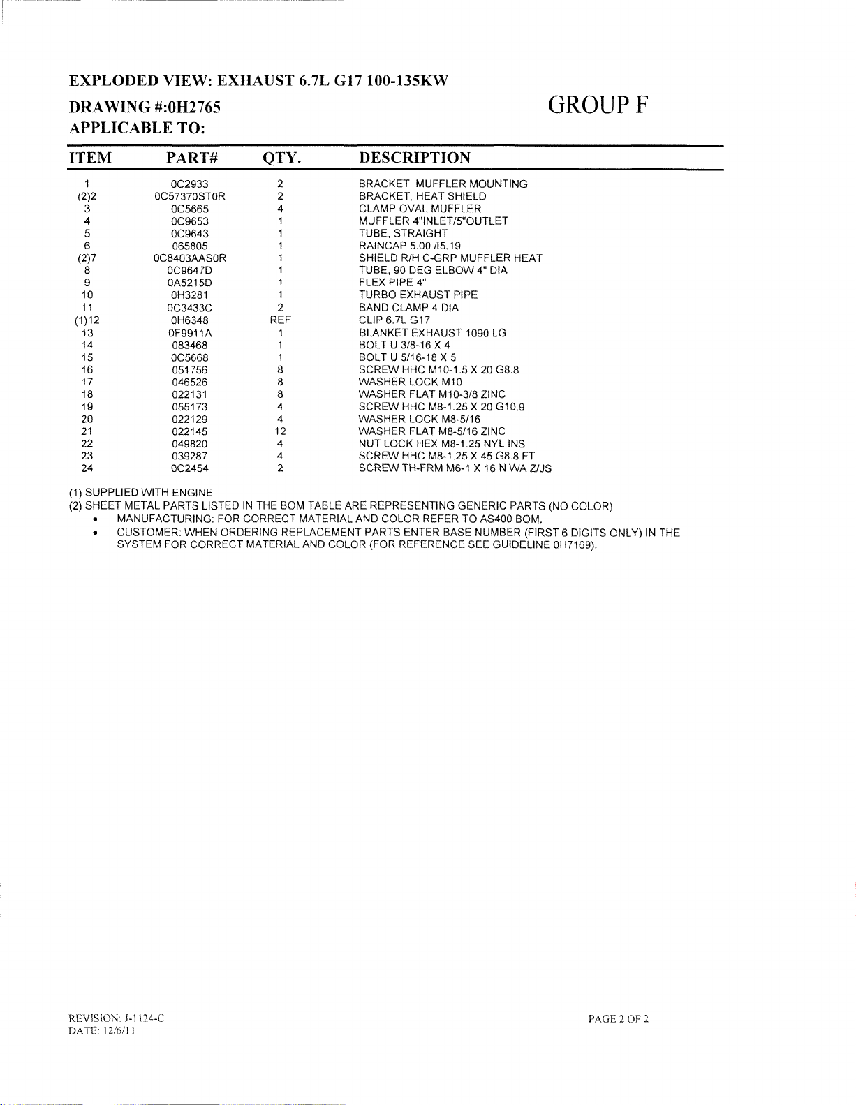
EXPLODED VIEW: EXHAUST 6.7L G17100-135KW
DRAWING
#:OH2765
APPLICABLE TO:
ITEM
1
(2)2
3
4
5
6
(2)7
8
9
10
11
(1)12
13
14
15
16
17
18
19
20
21
22
23
24
(1) SUPPLIED WITH ENGINE
(2) SHEET METAL PARTS LISTED
MANUFACTURING: FOR CORRECT MATERIAL AND COLOR REFER TO AS400 BOM.
CUSTOMER: WHEN ORDERING REPLACEMENT PARTS ENTER BASE NUMBER (FIRST 6 DIGITS ONLY) IN THE
SYSTEM FOR CORRECT MATERIAL AND COLOR (FOR REFERENCE SEE GUIDELINE OH7169).
PART#
OC2933
OC57370STOR
OC5665
OC9653
OC9643
065805
OC8403AASOR
OC9647D
OA5215D
OH3281
OC3433C
OH6348
OF9911A
083468
OC5668
051756
046526
022131
055173
022129
022145
049820
039287
OC2454
GROUPF
QTY.
2
2
4
1
1
1
1
1
1
1
2
REF
1
1
1
8
8
8
4
4
12
4
4
2
IN
THE BOM TABLE ARE REPRESENTING GENERIC PARTS (NO COLOR)
DESCRIPTION
BRACKET, MUFFLER MOUNTING
BRACKET, HEAT SHIELD
CLAMP OVAL MUFFLER
MUFFLER 4"INLET/5"OUTLET
TUBE, STRAIGHT
RAINCAP
SHIELD R/H C-GRP MUFFLER HEAT
TUBE, 90 DEG
FLEX PIPE 4"
TURBO EXHAUST PIPE
BAND CLAMP 4 DIA
CLIP 6.7L G17
BLANKET EXHAUST 1090 LG
BOLT U 3/8-16 X 4
BOLT U 5/16-18 X 5
SCREW
WASHER LOCK M10
WASHER FLAT M10-3/8 ZINC
SCREW
WASHER LOCK M8-5/16
WASHER FLAT M8-5/16 ZINC
NUT LOCK HEX M8-1.25 NYL INS
SCREW HHC M8-1.25 X 45 G8.8 FT
SCREW TH-FRM M6-1 X 16 N
5.00115.19
ELBOW
HHC M10-1.5 X 20 G8.8
HHC M8-1.25 X 20 G10.9
4" DIA
WA
ZlJS
REVISION J-1124-C
DA
TE 12/6/1 ]
PAGE20F2
Page 77

o
,
\ )
.....
STATES
STATES
FOAMISON
FOAMISON
<
---
,
---
,
---
,
NEAR
FAR
,
SIDE
,
(
I
I
SIDE
'---
---
---
I::l--
GROUPF
,
,
,
,
,
'1
I
I
I
I
I
I
tJ@
53
I
I
I
I
I
I
I
I
I
I
Revision:
Date:
10/6/11
H·9744-B
29
19
(
36
30
Page
1of4
Exploded
Drawing
18
View:EVENCL
No.:OJ0433
SAE
C·GRP
Page 78

EXPLODED VIEW:
EV
ENCL SAE C-GRP
DRAWING #:OJ0433
APPLICABLE TO:
ITEM
(1
)1
(1)2 OH98300STOR
(1)3
(1)4
(1)5 OH98320STOR
(1)6 OG63850STOR
(1)7
(1)8 OH97910STOR
(1)9
10
11
12 OC8391
13
(1)14
(1
)15 OG14150STOR
16
(1)17
18 OC7984
19 OC7983
20 OC7985
21
22
23
(1)24 OJ00780STOR
(1)25
(1)26 OJ00800STOR
(1)27
28 OJ0992
(1)29
30
31
32 OC3393
33
34 022129
35
36
37 022769
38
39
40 022473
41
42
43
44 OC2454
45 OE3257
46 OA9881
47 066760
48 027529
(1)49 OJ29770STOR 2
(1)50
51
(1)52
53
54
PART#
OH98290STOR
OH98340STOR
OH98310STOR
OH27690STOR
OJ
19690ALOR 1
OC7990
OC7989
OC7987
OH28160ALOR
OC2634A
OH98350STOR
OC8392
OC3595 8
OC3595A 8
OJ00790STOR
OJ00810STOR 2 DOOR
OJ16010STOR 8
OJ0993 8
OA5991
022145
042907
OC6749
080490
OC6748
022097
049813
026311 1
OJ02700STOR 2
087233
OC53560STOR
OE7222
OC3948
QTY.
1
1 CORNER
4 SIDE BRACE TOP&BTM C-GRP
1 CORNER POST LH FRONT C-GRP
1 CORNER
1
1 FRONT BRACE TOP 6.7L G17
2 CENTER DOOR SUPPORT
1 DUCT, FRONT LH
1
2
1
1 DUCT FRONT TOP R/H ALUM
2 RADIATOR
1
1 REAR SOUND BAFFLE, C-GRP
1 DUCT, REAR
1 DUCT, REAR RH
1
1 DUCT,REAR TOP
2
2 DOOR RH LOUVERED
2 DOOR
4 T-HANDLE, 2-POINT DBL DOOR
64
4
4
4
4
16
4
16
16 NUT HEX LOCK M4-0.7
17(REF)
17
16 NUT HEX M6-1.0 G8 CLEAR ZINC
112
14
1 TRIM
1 STRIP SEALANT
8(REF) NUT HEX LOCK 114-20 NY INS
16 RIVET POP .1875 X
1 PLATE VARMINT BLOCKOFF
2 RAIN SHIELD,DOOR
8
DESCRIPTION
POST
CORNER
LOWER RADIATOR BLOCK OFF
ASSY, ROOF C-GRP
DUCT, FRONT RH
DUCT, BOTTOM
DUCT, FRONT PANEL
ASSY
ACCESS
DUCT, REAR PANEL
ASSY M8 HINGE
ASSY M8 HINGE
DOOR LH LOUVERED
LH
RH
BRACKET, ROD GUIDE
ROLLER ROD, T-HANDLE
SCREW
SCREW
WASHER
WASHER
SCREW
SCREW
WASHER
WASHER
WASHER
WASHER
NUT LOCK HEX JAM
SCREW
SCREW
VINYL
DOOR BAFFLE
DOOR BAFFLE
SPACER
DOOR
LH REAR
POST
RH REAR
POSTRHFRONT
BLOCK
OFF 6.8L 135KW
COVER
LH
LH
SOLID
SOLID
8HSC
M8-1.25 X 16 SS
SHOULDER M8-1.25 X 20
FLAT 5/16-M8 ZINC
LOCK M8-5116
HHC M8-1.25 X 16 C8.8
PPHM M4-0.7 X 12 SS
LOCK INT #10
FLAT#8SS
FLAT 1/4-M6 ZINC
LOCK M6-1/4
HWHT
HWHTF M6-1.0 X 16
SEAL
(NOT
S5
1/4-20 NYL IN
M6-1 X 16 N
118
X 1 (NOT SHOWN)
.450 SS
JAMB
SHOWN)
C-GRP
NYL INS
WA
Z/JS
GROUPF
60 OJ0553EG
61
62
63
64 OJ0553BJ
65 OJ0553EH
66 OJ0553BI
67 OJ0553BL
68
69
REVISION H-9744-B
DA
TE
10/6111
OJ0553EF 2
OJ0553EE
OJ0553ED
OJ0553BM
OJ0621N
1 INSUL REAR DUCT SIDE
1 INSUL REAR DUCT LH SIDE
1 INSUL REAR DUCT
2 INSUL REAR CORNER POST
1 INSUL REAR DUCT TOP
8
1
1 INSUL ROOF MID
1
INSUL REAR DUCT SIDE
RH
SIDE
INSUL SIDE
INSUL ROOF REAR
INSUL HIGH HEAT FRONT ROOF
SUPPORT
RAIL
Page
2of4
Page 79

----------------
EXPLODED VIEW:
DRAWING #:OJ0433
EV
ENCL SAE C-GRP
GROUPF
APPLICABLE TO:
ITEM
70
71
72
73
74
75
76
77
78
79
80
81
82
83
84
85
86
(1) SHEET METAL PARTS LISTED
MANUFACTURING: FOR CORRECT MATERIAL AND COLOR REFER TO AS400 BOM.
• CUSTOMER: FOR CORRECT MATERIAL AND COLOR OF REPLACEMENT PARTS REFER TO "REPLACEMENT SHEET
METAL PARTS ORDERING GUIDE-OH7169" INCLUDED
PART#
OJ0621G
OJ0553BG
OJ0621H
OJ0553K
OJ0553L
OJ0553E
OJ0553Y
OJ0553M
OJ0553N
OJ0553EJ
OJ0553BH
OJ0553EA
OJ0553DZ
OJ0553CD
OJ0553EB
OJ0553EC
OJ0553EI
QTY.
2
2
1
2
2
2
2
2
2
2
1
1
1
1
2
1
1
IN
THE BOM TABLE ARE REPRESENTING GENERIC PARTS (NO COLOR).
DESCRIPTION
INSUL HIGH HEAT FRNT CNR POST
INSUL FRONT CORNER POST
INSUL HIGH HEAT FRNT CTR SPT
INSUL
RH
INSUL LH SOLID DOOR
INSUL CTR DOOR SUPPORT
INSUL DOOR BAFFLE
INSULRHLOUVERED DOOR
INSUL LH LOUVERED DOOR
INSUL DOOR BAFFLE
INSUL BOTTOM FRONT SUPPORT
INSUL FRONT DUCT LH SIDE
INSUL FRONT DUCT
INSUL FRONT DUCT BTM
INSUL FRONT
INSUL FRONT DUCT SIDE
INSUL REAR DUCT BAFFLE
SOLID DOOR
RH
SIDE
DUCT
SIDE
IN
THE MANUAL OR AVAILABLE ON THE GENERAC WEBSITE.
REVISION H-9744-B
DATE
10/6/11
Page 3
of4
Page 80

----------~
__
._--~-_._----
EXPLODED VIEW: EV ENCL SAE C-GRP
.
DRAWING
#:OJ0433
APPLICABLE TO:
This
page
left
blank
GROUPF
intentionally
REVISION H-9744-B
DATE
IO/61l1
Page
40f4
Page 81

GROUP G
7,09
0,35
6,39
----
1-.-------
~---------
f---
0,35
10,24
-----------------1-1
9,52
---------~
~-+-+--------+--+---.~
~~
~"
Dia Hole (0.236")
~
-
~
I
\ Cutout along this
line
gOO
Dia
4
places
cutout
Drill
for
For
mountingtowall
4
holes
-,'f----t---t---.-
+
6,75
REF
REVISION:
DATE: 03/26/08
-'----+----\-
Template for OG7879
Flush Mount
~nnunciator
1-.----------
21
BOX
Light
__
CB
-j-
9,88
-----------1-.]
REF
PAGE 1 OF 2
INSTALLATION
DRAVING~
OG8762
TEMPLATE
REV
A
EXPLODED
INSTALLATION
DRAWING
VIEW:
TEMPLATE
#:
OG8762
Page 82

EXPLODED VIEW:
DRAWING
#:
OG8762
INSTALLATION
TEMPLATE
GROUP G
APPLICABLE TO:
THIS PAGE IS LEFT INTENTIONALLY BLANK
REVISION:
DATE: 03/26/08
PAGE20F2
Page 83

1--------------------------------
OPTION 1 - SINGLE PHASE, H-PANEL OR G·PANEL CONTROL PANEL I
...J
W
:i
a..
<1
[~398A-WHITE
l5
~399A-----------------,
LEGEND
AR
AS
AVR-AUTOMATIC
CL
EF
MLCB-MAIN
NB
PME-PERMANENT
ALTERNATOR
-
ALTERNATOR
-
CURRENT
-
EXCITER
-
NEUTRAL
FIELD
CIRCUIT
ROTOR
STATOR
VOLTAGE
TRANSFORMER
BLOCK
BREAKER
MAGNET
REGULATOR
EXCITER
GROUPG
----------------,
I
I
'NOTE:
THE
g
#1
«
a..
I
I
~
~
::J
8
:::;;
Cl
Z
~[-
w - N2
(/l
_
~
~
~
~
THE
7TH
DIGITOFTHE
398B-WHITE-----------,
399B--------------,
00
-----;,.----,
Nl
8TH
DIGITOFTHE
MODEL
11
---+t----J
00l22_22
MLCB
E3
GENERATOR
CUSTOMER
El-E3
El-NORE3-N
MODEL
UNITS
NUMBER
2010TOPRESENT
"A"
= 120/240VAC 60HZ
"M" = 110/220VAC 50HZ
OUTPUT
CONNECTION
'240VAC
'120VAC
NUMBER
BEFORE
SPECIFIES
SPECIFIES
2010
NB
o
OUTPUT
OUTPUT
Xl
Xl
1--1--1--1-----
33 33
VOLTAGE
VOLTAGEONUNITS
ON
11
44
'5
DIRECT
DRIVE
GEARBOX
DRIVE
AS
'NOTE:
#5
WIRE
STATOR
(OPTIONAL)
THERMAL
USEDTOBYPASS
PROTECTOR
AGE1OF
L-
10
REVISION: J-1048-B
DATE:
1I115111
_
--------------------------------------~
WIRING - DIAGRAM
ALTERNATOR GIH-PANEL
PAGE 1 OF
10
DRAWING#:OH9846
Page 84

GROUPG
,---
I
-----------------------
OPTION
2 -
THREE
PHASE,
H-PANELORG-PANEL
CONTROL
PANEL,
I
I
I
I
I
I
I
I
d
~
#1
I
I
I
I
I
I
I
Cl
15
~398B-WHITE
d
~399B----------...,
z
~
~398C-WHITE
±
~399C--------,
12
398A-WHITE---------------,
399A.----------------.
,-----
S1
--+-+--+-+---1
I
I
I
I
I
S2
--+-+---1
I
LEGEND
AR
-
AS
-ALTERNATOR
AVR-AUTOMATIC
CT
_ -
EF
MLCB-MAIN
NB
-
PME-PERMANENT
X1
f---+++-----
X1
ALTERNATOR
CURRENT
EXCITER
NEUTRAL
TRANSFORMER
FlELD
CIRCUIT
BLOCK
X1
f--++--f--
ROTOR
STATOR
VOLTAGE
BREAKER
MAGNET
REGULATOR
EXCITER
S1
S2
I
I
I
I
I
I
I
I
I
I
I
I
I
I
I
I
I
I
I
I
I
*NOTE:
THE
lj
=>
8
::l:
Cl
z
~[-
w -
(/)
-
~
~
12
THE
7TH
DIGITOFTHE
N3
N2
---+-,
N1
E1TOE2J
E2TOE3
E1TOE3
E1,E2ORE3TO
8TH
DIGITOFTHE
MLCB
000
E1
E2
CUSTOMER
MODEL
GENERA
I "G" = 120!208VAC 60HZ I
I "K" = 277/480VAC 60HZ
L__________ _
53
E3
TOR
CONNECTION
*208VACOR*480VAC
NB
= *120VAC
MODEL
UNITS
NUMBER
BEFORE
NUMBER
2010TOPRESENT
SPECIFlES
1---+-+-+-------
o
~
OUTPUT
OR
SPECIFIES
2010
OUTPUT
ii
------
NB
*277VAC
OUTPUT
VOLTAGEONUNITS
VOLTAGE
S3
ii
ON
---------------,
DIRECT
DIRECT
DRIVE,6LEAD
DRIVE
l-
I
I
I
PME
)NAI
~~~
PAGE2OF
I
10 I
~
REVISION:
DATE: 11/15/11
J-I048-8
PAGE 2 OF
WIRING-DIAGRAM
ALTERNATOR GIH-PANEL
10
DRAWING#:OH9846
Page 85

,-----
I
OPTION
3 -
THREE
PHASE,
H-PANELORG-PANEL
LEGEND
AR
AS
AVR-AUTOMATIC
CT
_ EF
MLCB-MAIN
NB
PME-PERMANENT
--------------,
-
ALTERNATOR
-
ALTERNATOR
CURRENT
-
EXCITER
-
NEU1RAL
CONTROL
ROTOR
STATOR
VOLTAGE
1RANSFORMER
FIELD
CIRCUIT
BLOCK
MAGNET
BREAKER
PANEL,
REGULATOR
EXCITER
GEARBOX
(REVERSE
GROUPG
-----,
ROTATION)
G:l
~
~398A-WHITE--------------,
6
~399A----------------,
2S
G:l
z
.-:
c..
I
~
~
::J
Cl
o
::;:
Cl
Z
~[-
w - N2
VJ _ Nl
~
~398C-WHITE-------,
I
~399C-------....,
N3
t:l
~
§Z
~
"NOTE:
THE
8TH
THE
7TH
DIGITOFTHE
"AGE 3OF10
L _
REVISION: J-1048-B
DATE:
lI/IS/II
: _ 1
1 I 4
!~I:
398B-WHITE-----------,
3998-------------,
l-
.------
-BLACK
_-::
RED
:-a~
2 2
6 6
S3
--1-+---1-1--1
S2
--+-+---1
Sl
d1ft:j
--!J
_I
0 :
Xl
1---+-+--1-----
Xl
I--t-+--+---------
AR
P :
D~ECT
BRU:~LESS
Xl
I---+-+--+--
I
I
------,
-----,
S3
S2
Sl
---+-,
~~~
-------~W
S12 S12
MLCB
000
El
CUSTOMER
E1,E2ORE3TO
DIGITOFTHE
MODEL
"K- = 277
E2 E3
GENERATOR
ElTOE2J
E2TOE3
El
MODEL
UNITS
NUMBER
2010TOPRESENT
TO
E3
BEFORE
/480VAC
OUTPUT
CONNECTION
*480VAC
NB
NUMBER
SPECIFIES
o
~
= *277VAC
SPECIFIES
2010
OUTPUT
60HZ
NB
OUTPUT
VOLTAGE
VOLTAGEONUNITS
ON
~
~S7
/ .S8
l.-/
S5
S6
S9
o
-----------------------------------------~
WIRING - DIAGRAM
ALTERNATOR G/H-PANEL
PAGE 3 OF 10 DRAWING
#:
OH9846
Page 86

GROUPG
r
OPTION4-THREE
CT
~
[-+(~~+-
-
G:l
~
~398A-WHITE
<1
~399A----------------,
PHASE
DELTA,
H-PANELORG-PANEL
LEGEND
AR
-ALTERNA
AS
-
AItR-AUTOMATIC
CL
EF
MLCB-MAIN
NB
PME-PERMANENT
ALTERNATOR
-
CURRENT
-
EXCITER
-
NEUTRAL
TOR
ROTOR
STATOR
VOLTAGE
TRANSFORMER
FJELD
CIRCUIT
BLOCK
MAGNET
BREAKER
CONTROL
REGULATOR
EXCITER
PANEL,
DIRECT
I
===~
DRIVE,7LEAD
--------,
I
I
I
I
I
I
I
I
I
I
I
I
~
~398B-WHITE
G:l
~399B------------,
z
c::
~398C-WHITE
±
~399C-------...,
"NOTE:
THE
R
'::l
:;:)
8
::t
Cl
Z
~[-
w - N2
Ul
_
t5
~
R
THE
7TH
DIGITOFTHE
N3
N1
8TH
,.------
----!_+_,
DIGITOFTHE
MODEL
S1
..-----
--1-+--++---1
55
--++---H--\
S2
--I-+--{
S6
---!-1---\
X1
S3
S4
1---+++--------
1--1--+--+--------
MLCB
GENERATOR
CUSTOMER
E1TOE2J
TOE3"240VAC
E2
E1TOE3
E1-NORE3-N'""120VAC
MODEL
UNITS
NUMBER
2010TOPRESENT
"J"
'"
OUTPUT
CONNECTION
NUMBER
BEFORE
SPECIFIES
120!240VAC
SPECIFIES
2010
60HZ
OUTPUT
1---+++----
1--1--+--+-----
OO-OO
HB
o
f
OUTPUT
VOLTAGEONUNITS
L
X1
!--+++-
\--1--1--1--
VOLTAGE
ON
S5
S4
S2
S6
S3
S1
GEARBOX
DRIVE
AS
PAGE4OF
10
~
REVISION: J-I048-B
DATE: 11/15/11
PAGE 4 OF
WIRING-DIAGRAM
ALTERNATOR G/H-PANEL
10
DRAWING#:OH9846
Page 87

r-------------------------------------------------
I OPTION 5 - THREE PHASE SERIES WYE, H-PANEL
LEGEND
AR
-
AS
-AL1ERNATOR
AVR-AUTOMATIC
CT
_ -
EF
MLCB-MAIN
NB
-
OR
AL1ERNATOR
CURRENT
EXCI1ER
NEUTRAL
TRANSFORMER
FlELD
CIRCUIT
BLOCK
G-PANEL CONTROL PANEL, DIRECT DRIVE,12LEAD I
ROTOR
STATOR
VOLTAGE
BREAKER
1--------------,
1
1-
1
1
~
~
I 4 -
I: :
-BLACK
RED
--B~g'
l-
...J
W
~
~398A-WHI1E--------------,
eb
~399A,----------------,
2 2
6 6
~
------
REGULATOR
AR
F>
DIRECT
0----
BRU~~LESS
I
I
I
:
I
-------,
-----,
GROUPG
i
I
I
I
I
I
I
I
I
I
I
I
I
I
I
I
I
I
I
I
I
I
~
~398B-WHI1E
G:J
~399B:----------..,
X1
I---l-+-l-
= *231VAC
BEFORE
2010TOPRESENT
S12
2010
S1
S2
S3
~
S7
/ .S8
~
S5
S6
S9
AS
o
i'AGE 5
a..
~#
±
~
*N01E:
OF
E1-NORE2-NORE3-N
THE
THE
8TH
7TH
DIGITOFTHE
10 I
;
~
:::>
Cl
o
::::ii
Z
"
~[-
N3
w
-N2----+--"
(f)
_
N1
~
~
~
~
E1TOE2]
E2TOE3
E1TOE3
DIGITOFTHE
MODEL
398C-WHI1E------,
399C-------..,
,-----
MLCB
000
E1
E2
E3
GENERATOR
CUSTOMER
*480VAC
= *277VAC E1-N
MODEL
NUMBER
NUMBER
SPECIFIES
"K" = 277/480VAC 60HZ
= 231/400VAC 50HZ
"R"
S1
---+-+---+4--l
S2
--+-+----1
S3
OUTPUT
CONNECTION
SPECIFlES
OUTPUT
OUTPUT
X1
1--1-+-+-----
X1
1--+++-------
~~~-------~~~
S12
NB
o C
~
E1TOE2]
E2TOE3
E1TOE3
OR
E2-NORE3-N
VOLTAGEONUNITS
*400VAC
VOLTAGEONUNITS
~-------------------------------------------------~
WIRING - DIAGRAM
REVISION: J-I048-B
DATE: 11/15/11
PAGE 5 OF
10
ALTERNATOR GIH-PANEL
DRAWING#:OH9846
I
I
I
I
I
I
Page 88

,--------
I
I
I
I
I
I
I
I
I
I
I
I
OPTION
--------------
6 -
THREE
PARALLEL
ZIG
ZAG,
H·PANELORG·PANEL
LEGEND
AR
-ALTERNATOR
AS
AVR-AUTOMATIC
CL
EF
MLCB-MAIN
NB
-
1
1-
1
----
ALTERNATOR
CURRENT
EXCITER
NEUTRAL
TRANSFORMER
FIELD
CIRCUIT
BLOCK
ROTOR
STATOR
VOLTAGE
BREAKER
CONTROL
REGULATOR
----------------,
PANEL,
DIRECT
--------------,
-B~g<
~
--------------~
AR
P I
DIRECT
GROUPG
DRIVE,12LEAD
I
1
-BLACK
-
RED
G:l
~
0-
6
[~398A-WHITE
15
~399A,----------------,
g
#1
<
0-
I
I
398C-WHITE----------,
399C------------,
----
2 2
6 6
-
---
I?
(J)
(J)
w
z
a::
<
I
W
a::
;::
MLCB
~
~
GENERATOR
I
I
I
I
'NOTE:
THE
THE
8TH
7TH
DIGITOFTHE
DIGITOFTHE
MODEL
I
I
CUSTOMER
ElTO00l'115VACOR'120VAC
E3TOOOJ
ElTOE3]
MODEL
NUMBER
NUMBER
SPECIFIES
"A" - 120!240VAC 60HZ
a 115/200VAC 50HZ
"N"
Nl
N3
r-
0 <
OUTPUT
CONNECTION
'200VACOR'240VAC
SPECIFIES
OUTPUT
OUTPUT
VOLTAGEONUNITS
Xl
NB
VOLTAGEONUNITS
I
I
L _
REVISION: J-I048-B
DATE: 11/15/11
PAGE 6 OF
F
08
--
----
f---++-+-
DO-{~~
BRUSHLESS
----
Nl
511
1
1
I
DIRECT
~S658S12
~
BEFORE
2010TOPRESENT
10
2010
---------------~
DRIVE
AS
PAGE6OF
WIRING-DIAGRAM
ALTERNATOR G/H-PANEL
DRAWING#:OH9846
10
Page 89

GROUPG
,-------------------------------------------------,
I OPTION 7 - THREE PHASE SERIES DELTA, H-PANEL OR G-PANELCONTROL PANEL, DIRECT DRIVE, 12 LEAD I
LEGEND
AR
AS
AVR-AUTOMATIC
CL
EF
MLCB-MAIN
NB
ALTERNATOR
-
ALTERNATOR
-
CURRENT
-
EXCITER
-
NEUTRAL
ROTOR
STATOR
VOLTAGE
TRANSFORMER
FlELO
CIRCUIT
BLOCK
REGULATOR
BREAKER
1--------------
1
1-
1
-BLACK
J I 4
:
~
I: :
...J
W
~
~398A-WHITE-------------,
c1
~399A,-----------------,
-~
RED
l-
-"rED'"
2 2
6 6
__
------_--
~
AR
P 1
__
--
-?~ECT
0 :
BRU:~LESS
I
I
I
-------,
------,
I
I
I
I
I
I
I
I
I
I
I
I
I
I
I
I
I
I
I
?AGE7OF
L
15
~398B-WHITE
r;l
~399B-------------,
0.
~~
±
~
~
398C-WHITE:-------,
399C:---------,
N1
----l'--l----+-+----l
N2
--1-+--1
N3
X1
1--+'--1-'--1---
X1
~j
NB
o
~
000
E1
E2
E3
GENERATOR
CUSTOMER
E1TOE2J
E2TOE3
"NOTE:
E1-NORE2-NORE3-N
THE
THE
7TH
10 I
8TO~
8TH
DIGITOFTHE
DIGITONTHE
MODEL
"2400VAC
= "120VAC E1-N
MODEL
NUMBER
NUMBER
SPECIFIES
"0"
= 120/2400VAC
"J" = 120/240VAC 60HZ I
"p" = 100/200VAC 50HZ
OUTPUT
CONNECTION
SPECIFlES
OUTPUT
10/30
E1
TO
E2J I
E2TOE3
8TO~
OR
E2-NORE3-N
OUTPUT
VOLTAGEONUNITS
60HZ I
"200VAC I
VOLTAGEONUNITS
X1
N1
N2
CT2
S3
S10
-------
~j
~
~S8
S6
AS
S9
6
= "100VAC I
BEFORE
2010TOPRESENT
2010
I
I
~
REVISION: J-1048-B
DATE:
11115/11
PAGE 7 OF 10
WIRING - DIAGRAM
ALTERNATOR G/H-PANEL
DRAWING#:OH9846
Page 90

r------------
I
I
I
I
I
I
I
I
I
I
I
I
I
I
I
I
I
I
I
I
I
I
I
I
I
I
I
I
I
I
I
I
I
I
I
I
I
I
I
I
I
L
"NOTE:
THE
OPTION
THE
7TH
----------------------
8 -
THREE
PHASE
-'
l.U
~
~398A-WHITE
J,
~399A,----------------,
~
~398B-WHITE--------.
G:l
~399B----------..,
a.
~
~#
::1:
398C-WHITE-----...,
399C-------...,
R
~
l.U
Z
a::
«
:r:
l.U
a::
;:
N3
---+---t.
N2---h
Nl
8TH
DIGITOFTHE
DIGITOFTHE
MODEL
PARALLEL
WYE,
LEGEND
AR
AS
A~
CT_-CURRENT
EF
MLCB-MAIN
NB
,.-----
GENERATOR
CUSTOMER
ElTOE2J
E2TOE3 "208VAC
ElTOE3
El-NORE2-NORE3-N
MODEL
NUMBER
NUMBER
"G" =
SPECIFIES
SPECIFIES
120/208VAC
Nl
---+-+---+-+--1
--++----1
N2
N3
OUTPUT
CONNECTION
OUTPUT
H-PANELORG-PANEL
-ALTERNATOR
- AlTERNATOR
-
AUTOMATIC
-
EXCITER
-
NEUTRAL
= "120VAC
60HZ
ROTOR
STATOR
VOlTAGE
TRANSFORMER
FlELD
CIRCUIT
BREAKER
BLOCK
Xl
1-----+-+-+---
li
S11
S12
o
NB
~
OUTPUT
VOlTAGEONUNITS
VOLTAGEONUNITS
CONTROL
REGULATOR
Xl
I-----+--+--+-- Nl
PANEL,
DIRECT
DRIVE,12
cn
N2
CT2
S3
S9
DIRECT
DRIVE
-------!~
BEFORE
2010TOPRESENT
2010
Sll--
S12
.....
--.........;::....-_--
GROUPG
-----
LEAD
PAGE8OF
--,
10
I
I
I
I
I
I
I
I
I
I
I
I
I
I
I
I
I
I
I
I
I
I
I
I
I
I
I
I
I
I
I
I
I
I
I
I
I
I
I
~
REVISION: J-1048-8
DATE: 11/15/11
PAGE 8 OF
WIRING - DIAGRAM
ALTERNATOR GIH-PANEL
10
DRAWING#:OH9846
Page 91

----~~~
~----
GROUPG
r------------
OPTION 9 - THREE PHASE SERIES DELTA, H-PANEL OR G-PANEL CONTROLPANEL, GEARBOX (REVERSE ROTATION), 12 LEAD I
-------------------
LEGENp
AR
-ALlERNA
AS
AVR-AUTOMATIC
CL
EF
MLCB-MAIN
NB
ALlERNATOR
-
CURRENT
- EXCllER
-
NEUTRAL
TOR
ROTOR
STATOR
VOLTAGE
TRANSFORMER
FIELD
CIRCUIT
BREAKER
BLOCK
----------------,
REGULATOR
I
I
I
I
I
I
I
I
d
~
~398A-WHllE--------------,
c1
~399A----------------,
g§
~398B-WHllE---------,
d
~399B-----------,
Xl
I---+_+_-+--
N2
CT2
BEFORE
2010TOPRESENT
2010
Nl
Sl
S7
Sll-S12
-----''''''-----
.....
AS
*NOlE:
_'AGE9OF
a.
~#
±
~
w
Z
0::
«
:r:
w
0::
~
::J
::>
8
::::;:
o
z
w - N2
(/)
§;
THE
7TH
DIGITOFTHE
8TH
THE
10 I
~
398C-WHllE-----_,
399C-------_,
.-----
~
[-
N3
__
-
Nl
~ r"<:l--T"<:I---i'd-,
--1-,
~
MLCB
~
000
El
E2
E3
GENERATOR
CUSTOMER
ElTOE2J
E2TOE3
TO
El
DIGITOFTHE
El-NORE2-NORE3-N
MODEL
NUMBER
"G" =
NUMBER
SPECIFIES
MODEL
120j208VAC
Nl
-~_+_--+_+-__l
N2
--++---1
N3
OUTPUT
CONNECTION
*208VAC
E3
OUTPUT
= *120VAC
OUTPUT
60HZ
SPECIFIES
Xl
1----+-+-+---
Xl
~~----~~
S6 S6
S10 S10
S11
S12
o NB
~
VOLTAGEONUNITS
VOLTAGEONUNITS
~-------------------------------------------------~
WIRlNG - DIAGRAM
REVISION: J-1048-8
DATE: 11/15/11
PAGE 9 OF
ALTERNATOR
10
DRAWING#:OH9846
G/I~HANEL
I
I
I
I
I
I
I
I
I
I
I
I
I
I
I
I
I
I
I
I
I
I
I
I
I
I
I
I
I
I
I
I
I
I
I
I
Page 92

1---
I
I
I
I
PAGE
LEFT
BLANK
INTENTIONALLY
GROUPG
....,
I
I
I
I
I
I
I
I
I
I
I
I
I
I
I
I
L
PAGE10OF
10
WIRING-DIAGRAM
REVISION: J-1048-B ALTERNATOR GIR-PANEL
DATE:
11115/11
PAGE IOOF
10
DRAWING#:OH9846
~
Page 93

r--------------------------------
I
Will:iQ.
AH1-ALARM
ALT -DCCHARGE
AVR-AUTO
BCC
- BATTERY
BCH
- BATTERY
CB
CO
COM-COMMUNICATION
CT_-CURRENT
DB
ECM-ELECTRONIC
ES1-EMERGENCY
EXC-EXCITER
F_ FLS_-FUEL
GA_-GOVERNOR
GO-GOVERNOR
GFCI
GND-GROUND
1FT
- INTERFACE
.--------WHITE--------Hf'7>11-
HORN
ALTERNATOR
VOLTAGE
CIRCUIT
CROSSOVER
DIODE
BRIDGE
FUSE
LEVEL
GROUND
r----------------t-'-~>t_-
REGULATOR
CHARGER
CHARGER
BREAKER
FAULT
BAR
OPE
CONNECTOR
CONNECTOR
TRANSFORMER
CONTROL
STOP
SENDER
ACTUATOR
DRIVER
CIRCUIT
CONNECTION
TRANSFORMER
CONNECTOR
MODULE
SWITCH
r=
~~ ~~
IP
-
INTERRUPT
INJECTOR
L
ENGINE
LD
-
LEAK
MLCB-MAIN
MOD-MODEM
MPU1-MAGNETIC
NB
- NEUTRAL
OPS1-OIL
OTS_ -
OIL
R_
-
RESISTOR
RB_
- RELAY BOARD
RB_A
- RELAY
SC
-
STARTER
SM
STARTER
SW1
- OFF/AUTO/MANUAL
SWC-SWITCH
T8_-TERMINAL
WlLS_
- COOLANT
WTS_ -
COOLANT
PUMP
CONTROL
DETECTOR
LINE
CIRCUIT
CONNECTOR
PICKUP
BLOCK
PRESSURE
TEMPERATURE
BOARD
CONTACTOR
MOTOR
CONNECTOR
BLOCK
LEVEL
TEMPERATURE
MODULE
BREAKER
SENDER
SENDER
CONNECTOR
SWITCH
SENDER
CONN.
SENDER
COMPONENTS LOCATED IN ALTERNATOR CONNECTION BOX
WHITE
______
~-
I
IWHITE~
I
~399C--J2-9
i
~ ~
398A
399A
2
398B
1-'-1
~>+-
399B
-----.:-T.
398C
J2-12
J2-11
--
J2-35
--
J2-34
--
J2-10
I
i
-----------------l
NOTE:
ALL
OTHERWISE
AVR-3--
CB--
AVR-5--
WIRES18AWG
300VULLISTED
SHOWN
[
AVR-1--
UNLESS
6
2
4
1
-./-
GROUPG
EXC
3
PERMANENT
MAGNET
2
EXCITER
4
+
EXCITER
1
FIELD
TB2-7X
I
I
I
I
I
I
I
I
I--
~
--
cn
~!
CT2
~~~~.i'O'"
L-~T3
~
SEE
DRAWING
OH9846
COMPONENTS LOCATED IN HIGH VOLTAGE CUSTOMER CONNECTION MODULE
CONNECTIONS
FOR
------S1
------S2
------00
J2-6--224
J2-29--225
J2-17--226
J2-7--227
10
UNIT
S3
r-r-
-
NOTE:
ALL
SECTION
WIRESINTHIS
ARE
600V
RATED
TO
GENERATOR
-
2
3
4
1FT
5
6
7
8
~
9
L1
rl rl
MLCB
Q
l,Jl,Jl,J
L2 L3 N
ri
0
0
0
0
0
CONNECTIONS
30
FOR
..--
UNIT
31
32
33
00
NB
I
I
I
FORCTWIRING.
J2-6--224
J2-29--225
J2-17--226
J2-7--227
--I
I
I
I
I
I
I
-,
31
32
S3
00
,----
2
3
4
1FT
5
6
7
8
'---
9
~
AGE1~~
REV1SION: H-9136-D
DATE:
6/8111
PAGE 1 OF 6
CUSTOMER
CONNECTIONS
~
WIRING - DIAGRAM
D4.5L/D6.7L G17 12V
DRAWING#:OH9862
Page 94

r--------------------------------------------------------------l
COMPONENTS
TB4
x Y
LOCATEDINHIGH
VOLTAGE
CUSTOMER CONNECTION MODULE I
GROUPG
BCC-1
BCC-2--
BCC-3--
NOTE:
FOR
(TERMINAL STRIP)
MAXIMUM
RECOMMENDED
,---I--{J.;:s'l
GND
FIELD
WIRE
1==-.J.--l._O-=--L-L7·L~~;;~--
L----------N02
L-----------NC2
L-
L-
NOTE:
FOR
: (TERMINAL
LCOMMENDED
FIELD
MAXIMUM
REVISION: H-9136-D
DATE: 6/8/11
L1
N
-l.J..:i:J.-1l:'~
o
WIRINGTOCUSTOMER
SIZE:
#10
TIGHTENING
RUN
RELAY
W
14~r~,0
0
~O,,:\
00
o 0
CONNECTIONS
AWG
TORQUE:14LB-IN
2
f--
14
110
8
,::<J+--
COM1--
_~
OM
~
NC1
N01
TB5
X
Y
0 0
@1
@2
>-
«
-'
@3
w
<>::
@4
z
::>
<>::
@5
@6
0
0
WIRINGTOCUSTOMER
STRIPS
AND
SIZE:
RELAY BOARD)
#14
AWG
~ORQUE:
WIRE
_TIGHTENIN~
N01
COM1--RR-1
NC1--RR-4
N02
OM2--RR-8
NC2--RR-5
CONNECTIONS
_1~
2--
0
--
--TB5-1X
LB-IN
TB5TB5-5X
TB2-6Y
TB5-4X
TB5-6X
TB5-3X
RR-3
RR-6
GND
N
L1
OR
L1
GND
L2
-
L1
-GND--~I
L2-------.....J
2X
TB4
OR
CENTER
TB4
OR
CENTER
I :
I I
LOAD
LOAD
120/240
UTILITY SUPPLY
(BY
LOAD
VERIFY
RATINGS
SUPPLY
TOBEPROVIDED.
____
VAC
CUSTOMER)
125A
CENTER
COMPONENT
FOR
PROPER
VOLTAGE
O~T~O~
I
I
i :
I I
i :
I I
i :
I I
SUPPLIED
i :
I I
i :
I I
I
GROUNDED
TYPICALLY I
PLUG
REMOVED
INSTALLER
AND
TEF:MI~IATlcDIN
-
~~~~WHtjITEt=~(=
WITH
3-
WIRE
PW~
IS
BY
THE
WIRES
ARE
BOX
--
- - -
BLACK
GREEN
--
~
THERMOSLTA
L-
JUNCTION
- - - -
BOX
D
T 1
FOR
CUSTOMER
CONNECTIONS
N (BATTERY I
-o
GND
WARMER
OIL
HEATER)
COMMON
-- --
AND
OPTI~
- -PAGE 2
OF
8 I
I
II
II
I
I
I
I
I
I
I
I
I
---------------------------------~
PAGE
20F6
WIRING
DRAWING#:OH9862
- DIAGRAM
D4.5L1D6.7L
017
12V
Page 95

r--------------------------------------------
COMPONENTS
LOCATEDONLOW
VOLTAGE
GROUPG
-----------------l
CUSTOMER CONNECTION PANEL I
.[C~
S
NC
<{
NO
U1
x
NC
t-
::>
::>
<{
0..
t-
NO
f'
::>
0
w
0::
<{
0..
S
NC
"['~
U1
<{
NO
s
NC
t~
0«
NO
K310
RB3
li--15A_-
"
RB3A
2--0C5-3--0C6-4--15A-5--0C7-6--0C8--
GRN-@
GROUND
TB2-1X
J2-23
J2-22
TB2-1X
J2-33
J2-21
STUD
TB1
X
Y
0 0
o
--
Wt-[
b~
:::;;U1
at-
Eo«
:::;;t-
~(J)
:::;;t-
is
~
uo..
w
ffi
~1S'
--.J
0.. L
0::
zW
W5:
00
0..
(J)
z
0
F
u
w
z
z
0
U
0::
w
:::;;
a
t-
(J)
::>
u
0@1
183
@2
@3@
@4
["~~
RS485-
@5
SHLD
@6
@7@
~-1
~-
_____
I I
I I
8
9
11
12
0
183--
390--
391
SHLD
DI3--
0
0
DI4
0
TB2-8X
J2-4
J2-13
J2-1
J2-24
J2-3
0 0
TB2
Y X
o 0
8 u [ @ 1
<g
0
u..
@2NI---15A--
~
z [
@3NI---14--
0::>
r5
0:: @ 4 * *
D 5 D (CATHODE)
~
~
@ 6 POLARIZATION.
~
@ 7
NI---
[
@8NI::---
o
L J
,'AGE 3OF6 I
REVISION: H-9136-D
DATE: 6/8/11
15A-15A--
0 TB1-1X (TERMINAL
o
RB3A-1
RB3A-4
CO-7
CO-8
NOTE:
TB2-4X
EXC-1
CO-6
ENSURE
IS
FOR
PAGE 3
LINEOFDIODE
CLOSEST
CORRECT
OF6
TO
NOTE:
FOR
FIELD
MAXIMUM
RECOMMENDED
WIRINGTOCUSTOMER
STRIPS
AND
WIRE
RELAY
SIZE:
#14
TIGHnENING
AWG
TORQUE:12LB-IN
CONNECTIONS
BOARD)
WIRING - DIAGRAM
D4.5L/D6.7L
DRAWING#:OH9862
017
12V
I
Page 96

r----------
J2-14
J2-2
J2-25
387
388
389
COM
0",
0
0
COMPONENTS LOCATEDINCONTROL PANEL
MOD
Jl-14-811
J1-26
-809
810
- 812
------
812~
8_1_1
]
-
GROUPG
--------------------l
ALT
TB3-8X
J1-23
----5f;A---------------------J
J1-34
J2-5~174
J2-28~175-+.~+-----,
GND
TB2-8X
00-1
GD-l0
BCC-7
Jl-l0
J1-11
TB2-3X
IP
_-=~
I
TB2-2X
--\<{-C+--------15A,---+N
49
14
1 1 1
2
3 6 6
4 4
5 4
6
AVR
445------------------------f--+--+------44:i-
~
l J
7
8
9
10
11
12
13 162 2
14
IIl4l
~
~
---l-LQ..L-
49
194--+------Hl4--J2-31
------403
404
406-------406-J2-30
405
o
o
o
o
o
R15B
256
15
14
14
I
I
I
I
SC
I
---JmJLL::t-L-
13
I
I
I
I
L
REVISION: H-9I36-D
DATE:
6/8/ll
o
ES1
TB3
y
403-
404-
405-J2-19
-
+
AH1
X
PAGE 4 OF 6
-TB2-4X
-PME-3
4
PME-4
J2-8
J2-20
PME-2
swc
r---:r
H
229
2
15A
'---
0
0
0
R15B
R15B
256
15
14
14
-------t--------t-----t--------
15A
tD
<f)
oc
I
«
<f)
--------------------------~~~~~~
0 N
@8
@5
@2
10
9
6
3
14
15B
[J
E
PCB
I
'E,,"
[J
0
I
Jl-12
DB
Jl-35
56
<D
CI>
:R
<f)
N
'!2
N
n::
-L.w.u._.IF---------
00-4
14 7
14
15A
15A
15E 4
0
229
WIRING-DIAGRAM
D4.5LID6.7L
Gl7
I2V
DRAWING#:OH9862
Page 97

r-------------------
I
,------------
r----------
LOCA
TED
BACKOFCONTROL
COMPONENTS LOCATED ON ENGINE
Bee
0
13
PANEL
,++-+---17r
rl--+-+-+--B
J1
-16
-+--+-+-+--+-t7-r-1---803
----'
+-
,---B.)'1-+u..=LL-
2
r+---b;F
rl--+-t7
)"3-+u..=L.L-GN
5
-f-JLL:!..L
:,.:.4+-,-",-,_ 0
'--_-'='1~L1-----------t<~t_TB4
L-----L1L:U-Gt~D-----------_t<~:=t-TB4
L1
--j-1..L:!.J- N
D
13
4 N TB4ORLOAD
OPTIONAL
1-----
BCH
I
L1
(HOT) :
N (NEUT) :
GND
+ (POS) :
lOA
CHARGER
I
ONLY
8Jw
:
~'§
:c<~
[5"-
=_~~~~U
CHARGE
I I
L
CURRENT
LOCATED
C.9~TROL
IN
PAN~L---l
----------------l
Bee
5005~,
~
I
I
---'-L"-'-
GROUPG
eo
~_1
__
J2-27
TB3-3Y
OR
LOAD
CENTER
LOAD
13 -
CENTER
CENTER
TB3-12Y
OR
I
I
I
I
I
I
I
I
I
I
I
I
I
I
I
I
I
I
I
I
I
I
I
I
LD-1-
OTS-3-
WTS-3
- 0
I'v1LS-3 - 0
GA-3
TB3-1
Y - 0
FLS-3
0
-----------,
I'v1RE
ON
0
------------'
-----------'
0
~~---------'
--LL:U
0
-------------'
LOCATIONS
MAY
CHANGE
GROUND
BAR.
'--+-------+-+-------
000
0000
0000000
.--J
---'
GND
I~
~ECM
'-++-11--'-'-"--'--- 16
CHASSIS
56
o
-----t------,
----------------
+
12V
BATTERY
56-RB1-10
49
-----
49
-
R2
~~~~~~
REVISION: H-9136-D
DATE: 6/8/11
PAGESOF6
WIRING
- DIAGRAM
D4.SLID6.7L
017
12V
DRAWING#:OH9862
J
Page 98

I·~---------
!
r
I
I
I
:TB3-2Y-
RB1-
TB3-2Y-
J1-33
GND
Jl-17
Jl-18
0
7 - 14
-769-------I---If-
766R
-766V
---------
-------j---jf-
0
-------j---jf-
0
--/+;c
-----'.;'+'"
GA
0
770
771
14
0
769
COMPONENTS LOCATEDONENGINE
GO
~fi
0
LOCATED
CONTROL
IN
PANEL
GROUPG
---------l
I
I
I
I
~i/fi3--11
I
I
I
I
I
GND
I
Jl-6
I
Jl-7-575V-----------',~y/
I
I
J2-15-567~
I
GND-O-II
I
I
I
I
I
I
I
I
I
I
I
I
I
I
I
I
I
I
I
I
I
I
I
I
I
I
I
I
I
I
I
I
I
I
I
L _
REVISION: H-9136-D
DATE:
0
---------H-,<J
575R----------\--t"-<J
CO
6/8111
ow
"
LI")
,~,
!'W'
"
I
OtO
\
I,{)
I
3
'~
OLl")-
mr---.(J)
uHf)
I
LD
\.(j>.~tlI
GAl
I,{)
FLS1
------~
o
-GND
Jl-9
-Jl-8
r---------------------68V--
.----------------------68R-
r-------69\/-Jl-20
.--------69Fl-Jl-19
lr
F
0'"
l
o
-GND
o
-GND
0
9-Jl-25
Jl-15
Jl-31
Jl-30
Jl-29
Jl-24
ECM
CHASSIS
"
2
WTSl
WLSl
OPS1
----------------------------------~~~~~~
PAGE60F6
WIRING
DRAWING#:OH9862
- DIAGRAM
D4.5L/D6.7L
Gl7
12V
Page 99

r-------------------------------I------------
I
PME
OR
DPE
N
co
U
STATOR
<D
....
>
""
>
""
<{
<{
c;::
""
T1
~
13
~o
~~
<{w
>-
a
z
......
ALTERNATOR
MAIN
TERMINALS
L1
~1L
---'-'-+--"---+---'~-------_>-----
k I
L3
00
<{
ro
t') t')
'"
N
--,
GROUPG
------------------1
ALTERNATOR
MAIN
:
STATOR
I
L1
T2
L2
I
K
CT2
L
k I
co
~
U;
ro
t')
'"
N 0
'"
U1
t')
I
I
L31
PME
I
OR
I
DPE
,+-_-+_+-_-1_+°_°_-+-
00
I
I
I
N
0
<D
co
Cl::
U
>
I
<{
""
....
Cl::
>
<{
c;::
13 L3
<{
ro
t')
'"
I
TERMINALS
CT1
L
k I
CT2
L
K
k I
CT3
K
k I
__
+-';-_-11--+-_-+_+---+--+_
co
0
'"
ro
t') t')
'"
'"
L1
L2
L
L3
00
I
224
J2
225
[
227
AL
TERNA
TOR
L
+-_-t-_H_-lo
r--t--H--Io
r+-+--l<l.
H-++--j{)10
Y-+-1-+--+--1O-'3_
1FT
-
-
-
~~
CONNECTIONS
02
...J
0
3
!2!
4
<{
05
0..
06
c5
o
07
g:
8 Z
",>--
8
011
FOR1¢UNITS
o
o o o o
I
I
I
I
:
I
:01
-02
'--03
~
04
0
Ir~
~
~
I
I
I
:
I
i~I
: OT51 :
~~O~~
AL
J2
[
TERNA
224
225
226
227
TOR
1FT
CONNECTIONS
N
--,
n
IP
FOR3¢UNITS
N.C.
>
"'01
<D <D
3 2 1
t:J
OP51
'"
,....
MPU1
j
a
...J
I
0
U1
L~~~~~
REVISION: -ADATE: 7/12/10
PAGE I
OF4
SCHEMATIC-DIAGRAM
D4.5L1D6.7L
Gl7
I2V
DRAWING#:OH9863
J
Page 100

MLCB
GROUPG
L1----+--
--I
L2--+--+-30
ON~
~
------------------------------------------------------
-----t-----
---------.---
----
-.----------------------
4)
.-----.---.------------------+---<) E2
1--]
~_O!::LY
NOTE
J2 183
J2 [
J2 [
390
391
013
014
5 15A
0
0
o 183
0013
o
0014
E1
00
GND
]
1l!~:oJ
0
;:«z
1>-0
N(I)[7j
]
::::>0
"-
d]
n::
]
i5~
°0
CL
DC
LOU1
co:::E
....
(/)0
n::o
RS485+ ]
RS485-
SHLD
COM
COM
FUSED
ENGINE
RUNNING
:::E
U1
>-
n::::::>
w"-
:::EZ
0-
>-...J
U1«
::::>>-
013
0
0
0
n::
f2
U1
z
0
F
0
W
Z
z
w
:::E
U1
::::>
0
SC
L-------+---O--~--O--+------'
NOTE:
FOR
FIELD
(TERMINAL
MAXIMUM
RECOMMENDED
WIRINGTOCUSTOMER
STRIPS
WIRE
AND
RELAY
SIZE
#14
TIGHTENING
CONNECTIONS
BOARDS)
AWG
TORQUE12LB-IN
L________________ _
>-
...Jo
"-«
0..>
Ll
----..-~-:----:--~~~-=-=.--::_g_
I-.GIN~D----_i_-l_-'---~..____o
o
~
o
z
r')
t;
]
~ND
::::>0
U1..,.
~~
_0
---'N
F-
::::>
I
I
I
I
I
I
I
I
I
I
I
I
I
I
I
I
I
I
I
I
I
UTILITY
OPTIONAL
POWlERED_
_ I
--.J
I
I
I
I
I
I
I
I
I
I
I
I
Y~~l~~J
I
REVISION: -A-
DATE:
7/12110
PAGE
20F4
SCHEMATIC-DIAGRAM
D4.5L1D6.7L
G17
12V
DRAWING#:OH9863
 Loading...