

Page 1
Owner’s Manual and
Installation Instructions
Air-cooled Recreational Vehicle Generator
• Model No: 00941-4
IMPACT-36 plus II with Inverter
This manual should remain with the unit.
Page 2

Generac®Power Systems, Inc.
INTRODUCTION
Thank you for purchasing this generator by Generac
Power Systems, Inc. This model is designed and
manufactured to supply electrical power for recreational vehicles.
READ THIS MANUAL THOROUGHLY
If any portion of this manualis not understood, contact the nearest Generac Authorized Service Dealer
for starting, operating, and servicing procedures.
Throughout this publication, and on tags and
decals affixed to the generator, DANGER, WARNING,
CAUTION, and NOTE blocks are used to alert personnel to special instructions about a particular
operation that may be hazardous if performed incorrectly or carelessly. Observe them carefully. Their definitions are as follows:
After this heading, read instructions that, if not
strictly complied with, will result in serious personal injury, death or severe property damage.
After this heading, read instructions that, if not
strictly complied with, may result in personal
injury or property damage.
After this heading, read instructions that, if not
strictly complied with, could result in damage to
equipment and/or property.
NOTE:
After this heading, read explanatory statements
that require special emphasis.
These safety warnings cannot eliminate the hazards
that they indicate. Common sense and strict compliance with the special instructions while performing
the service are essential for preventing accidents.
Four commonly used safety symbols accompany the
DANGER, WARNING, and CAUTION blocks. Here are
the types of information indicated by each symbol:
This symbol points out important safety information that, if not followed, could endanger
personal safety and/or property to self and others.
This symbol points out potential explosion hazard.
This symbol points out potential fire hazard.
This symbol points out potential electrical
shock hazard.
The operator (i.e., the driver) is responsible for the
proper and safe use of the vehicle and its equipment,
and for the safety of all vehicle occupants. Before
using this equipment, we strongly recommend that
the operator read this manual and thoroughly understand all instructions. We also strongly recommend
instructing other occupants in the vehicle to properly
start and operate the generator. This prepares them
to operate the equipment in case of an emergency.
CONTENTS
This manual contains pertinent owner’s information,
including warranty, electrical diagrams, exploded
views, and lists of repair parts for generator models
000941-4. In addition, the latter portion of this manual contains information necessary for the proper
installation of these generators.
OPERATION AND MAINTENANCE
It is the operator's responsibility to perform all safety checks, to make sure that all maintenance for safe
operation is performed promptly, and to have the
equipment checked periodically by a Generac
Authorized Service Dealer. Normal maintenance service and replacement of parts are the responsibilities
of the owner/operator and, as such, are not considered defects in materials or workmanship within the
terms of the warranty. Individual operating habits
and usage contribute to the need for maintenance
service.
Proper maintenance and care of the generator minimize problems and operating expenses. See the
Generac Authorized Service Dealer for service aids
and accessories.
HOW TO OBTAIN SERVICE
When the generator requires servicing or repairs,
simply contact a Generac Authorized Service Dealer
for assistance. Service technicians are factory-trained
and are capable of handling all service needs.
When contacting a Generac Authorized Service
Dealer or the factory about parts and service, always
supply the complete model number and serial number of the unit, as given on its data decal, which is
located on the generator.
Model No. ____________ Serial No. ______________
◆
◆
◆
◆
AUTHORIZED SERVICE
DEALER LOCATION
To locate the nearest GENERAC AUTHORIZED
SERVICE DEALER, please call this number:
1-800-333-1322
ONLY DEALER LOCATION INFORMATION
CAN BE OBTAINED AT THIS NUMBER.
DANGER
!
Page 3

Table of Contents
IMPACT-36 plus II Recreational Vehicle Generator
Generac®Power Systems, Inc. 1
Part I – Owner’s Manual
Introduction ....................................................Inside Front Cover
Read This Manual Thoroughly ............................................IFC
Contents ..............................................................................IFC
Operation and Maintenance ................................................IFC
How to Obtain Service ........................................................IFC
Authorized Service Dealer Locator Number ............................IFC
Safety Rules ....................................................................................2
Section 1 – General Information ..............................................4
1.1 Generator Identification ..................................................4
1.2 Generator Applicability ....................................................6
1.3 Safety ..............................................................................6
1.4 Generator Control Panel ..................................................6
1.5 Engine Protective Devices ................................................7
Section 2 – Operation..................................................................7
2.1 Before Starting the Engine ..............................................7
2.2 Starting the Generator ....................................................8
2.3 Stopping the Generator ..................................................8
2.4 Applying Loads to Generator ..........................................9
2.5 Attention Required After Submersion ..............................9
2.6 Operation in High Grass or Brush ..................................9
2.7 Operating Precautions ....................................................9
2.8 Fuel Requirements (LP Units)..........................................9
2.9 Engine Oil Requirements ................................................9
2.10 LP Generator Specifications ............................................9
2.11 Engine Specifications ......................................................9
Section 3 – Maintenance ..........................................................10
3.1 Maintenance ..................................................................10
3.2 Checking the Engine Oil Level ......................................10
3.3 Change Engine Oil ........................................................10
3.4 Change Oil Filter............................................................10
3.5 Engine Air Cleaner ........................................................11
3.6 Clean Air Intake Screen ................................................11
3.7 Engine Spark Plug ........................................................11
3.8 Inverter ..........................................................................11
3.9 Cleaning the Generator ..................................................11
3.10 Battery ..........................................................................12
3.11 Service and Adjustments ..............................................12
3.12 Adjusting the Carburetor ..............................................12
3.13 Adjusting Valve Clearance ..............................................12
3.14 Major Service Manual ....................................................13
3.15 Exercising the Generator ..............................................13
3.16 Out of Service Protection ..............................................13
3.17 Return Unit to Service After Storage..............................13
Section 4 – Notes........................................................................14
Part II – Installation Instructions
Safety Rules..................................................................................16
Section 1 – General Information ............................................18
1.1 Purpose and Scope of the Manual............................18
1.2 Safety ......................................................................18
1.3 Standards Booklets..................................................18
1.4 Equipment Description ............................................18
1.5 Engine Generator Operating Speed ..........................18
Section 2 – Installation ............................................................19
2.1 Location and Support ....................................................19
2.2 Generator Compartments ..............................................20
2.3 Cooling and Ventilating Air ............................................23
2.4 Propane Gas Fuel System ..............................................25
2.5 Exhaust System ............................................................27
2.6 Electrical Connections ..................................................28
2.7 Battery Installation ........................................................31
2.8 Optional Accessories......................................................32
Section 3 – Post-installation Startup Checks ......................33
3.1 Post Installation Tests ....................................................33
3.2 Before Initial Startup ....................................................33
3.3 Initial Start ....................................................................33
3.4 Testing Under Load ......................................................33
3.5 Installation Checklist ....................................................34
Section 4 – Troubleshooting ....................................................35
4.1 Troubleshooting Guide ..................................................35
Section 5 – Electrical Data........................................................36
Section 6 – Exploded Views and Parts Lists ........................38
Section 7 – Installation Diagram ............................................47
Section 8 – Warranty..................................................................48
Page 4
2 Generac®Power Systems, Inc.
Study these SAFETY RULES carefully before
installing, operating, or servicing this equipment.
Become familiar with this manual and with the unit.
The generator can operate safely, efficiently, and reliably only if it is properly installed, operated, and
maintained. Many accidents are caused by failing to
follow simple and fundamental rules or precautions.
Generac cannot possibly anticipate every possible cir
cumstance that might involve a hazard. The warnings in this manual, and on tags and decals
affixed to the unit, are, therefore, not all-inclusive. If
using a procedure, work method, or operating technique that Generac does not specifically recommend,
satisfy yourself that it is safe for others. Also make
sure the procedure, work method, or operating technique chosen does not render the generator unsafe.
Despite the safe design of this generator,
operating this equipment imprudently, neglecting its maintenance, or being careless can cause
possible injury or death. Permit only responsible and capable persons to operate and maintain this equipment.
Parts of the generator are rotating and/or hot
during operation. Exercise care near running
generators.
Potentially lethal voltages are generated by
these machines. Ensure all steps are taken to
render the machine safe before attempting to
work on the generator.
GENERAL HAZARDS
• For safety reasons, Generac recommends that the
installation, initial startup, and maintenance of
this equipment be performed by a Generac
Authorized Service Dealer.
• The generator engine releases DEADLY carbon
monoxide gas through its exhaust system. This
dangerous gas, if breathed in sufficient concentrations, can cause unconsciousness or even death.
Never operate the generator set with the vehicle
inside any garage or other enclosed area. DO NOT
OPERATE THE GENERATOR IF THE EXHAUST
SYSTEM IS LEAKING OR HAS BEEN DAMAGED.
SYMPTOMS OF CARBON MONOXIDE POISONING ARE (a) inability to think coherently, (b) nausea, (c) vomiting, (d) twitching muscles, (e) throbbing temples, (f) dizziness, (g) headaches, (h)
weakness, and (i) sleepiness. IF EXPERIENCING
ANY OF THESE SYMPTOMS, MOVE INTO FRESH
AIR IMMEDIATELY. IF SYMPTOMS PERSIST, GET
MEDICAL HELP. Shut down the generator and do
not operate it until it has been inspected and
repaired.
• Never sleep in the vehicle while the genset is running unless the vehicle has a working carbon
monoxide detector. The exhaust system must be
installed in accordance with the genset installation
manual. Make sure there is ample fresh air when
operating the genset in a confined area.
• The engine exhaust fumes contain carbon monoxide, which can be DEADLY. This dangerous gas, if
breathed in sufficient concentrations, can cause
unconsciousness or even death. Thus, the exhaust
system must be installed properly, in strict compliance with applicable codes and standards.
Following installation, do nothing that might render the system unsafe or in noncompliance with
such codes and standards. The generator compartment must be completely vapor-sealed from
the vehicle interior. There must be no possibility of
exhaust fumes entering the vehicle interior. Never
operate this equipment with a leaking or defective
exhaust system.
• Keep hands, feet, clothing, etc., away from drive
belts, fans, and other moving or hot parts. Never
remove any drive belt or fan guard while the unit is
operating.
• Adequate, unobstructed flow of cooling and ventilating air is critical to correct generator operation
and is required to expel toxic fumes and fuel
vapors from the generator compartment. Without
sufficient cooling airflow, the engine/generator
quickly overheats, which seriously damages the
generator. Do not alter the installation or permit
even partial blockage of ventilation provisions, as
this can also seriously affect the safe operation of
the generator.
!
!
Safety Rules
IMPACT-36 plus II Recreational Vehicle Generator
SAVE THESE INSTRUCTIONS – The manufacturer suggests that these rules for safe
operation be copied and posted in potential hazard areas of the recreational vehicle.
Safety should be stressed to all operators and potential operators of this equipment.
!
!
The engine exhaust from this product
contains chemicals known to the state
of California to cause cancer, birth
defects, or other reproductive harm.
WARNING:
This product contains or emits chemicals
known to the state of California to cause
cancer, birth defects or other reproductive harm.
WARNING:
!
!
!
!
DANGER
!
!
Page 5

Generac®Power Systems, Inc. 3
• When working on this equipment, remain alert at
all times. Never work on the equipment when
physically or mentally fatigued.
• Inspect the generator regularly, and contact the
nearest Generac Authorized Service Dealer immediately for parts needing repair or replacement.
• Before performing any maintenance on the generator, disconnect its battery cables to prevent accidental startup. First, disconnect the cable from the
battery post, indicated by a NEGATIVE, NEG, or
(–). Reconnect this cable last.
• Never use the generator, or any of its parts, as a
step. Stepping on the unit can stress and break
parts, resulting in dangerous operating conditions
due to leaking exhaust gases, fuel leakage, oil leakage, etc.
• Never insert any tool or other object through openings in the generator interior, even if the unit is not
running. Seriouse injury or damage to the equipment may occur.
ELECTRICAL HAZARDS
• The generator covered by this manual produces
dangerous electrical voltages and can cause fatal
electrical shock. Avoid contact with bare wires, terminals, connections, etc., while the unit is running.
Before operating the generator, ensure all appropriate covers, guards, and barriers are in place . If
work must be donearound an operating unit,
stand on an insulated, dry surface to reduce shock
hazard.
• Do not handle any kind of electrical device while
standing in water, while barefoot, or while hands
or feet are wet. DANGEROUS ELECTRICAL
SHOCK MAY RESULT.
• During installation onto the vehicle, have the generator properly grounded (bonded), either by solid
mounting to the vehicle frame or chassis, or by
means of an approved bonding conductor. DO
NOT disconnect the bonding conductor, if so
equipped. DO NOT reconnect the bonding conductor to any generator part that might be removed or
disassembled during routine maintenance. If the
grounding conductor must be replaced, use only a
flexible conductor that is of No. 8 American Wire
Gauge (AWG) copper wire minimum.
• In case of an accident caused by electric shock,
immediately shut down the source of electrical
power. If this is not possible, attempt to free the
victim from the live conductor. AVOID DIRECT
CONTACT WITH THE VICTIM. Use a nonconducting implement, such as, a dry rope or board, to
free the victim from the live conductor. If the victim
is unconscious, apply first aid and get immediate
medical help.
• Never wear jewelry when working on this equipment. Jewelry can conduct electricity, resulting in
electric shock, or may get caught in moving components, causing, injury.
FIRE HA
ZARDS
• For fire safety, the generator must be installed and
maintained properly. Installation must always
comply with NFPA 70 (latest edition), “National
Electrical Code”, Article 551, and NFPA 1192 (latest edition), “Standard for Recreational Vehicles”,
along with all applicable codes, standards, laws,
and regulations. Adhere strictly to local, state, and
federal electrical and building codes. Comply with
regulations the Occupational Safety and Health
Administration (OSHA) has established. Also,
ensure that the generator is installed in accordance with the manufacturer’s instructions and
recommendations. After proper installation, do
nothing that might alter the installation and render
the unit in noncompliance with the aforementioned codes, standards, laws, and regulations.
• Keep a fire extinguisher in the vehicle at all times.
Extinguishers rated “ABC” by the National Fire
Protection Association are appropriate for use on
the recreational vehicle generator electrical system. Keep the extinguisher properly charged and
be familiar with its use. If there are any questions
pertaining to fire extinguishers, consult the local
fire department.
EXPLOSION HAZARDS
• Do not smoke around the generator. Wipe off any
fuel or oil spills immediately. Ensure that no combustible material is left in the generator compartment, or on or near the generator, as FIRE or
EXPLOSION may result. Keep the area surrounding the generator clean and free of debris.
• All fuel types are potentially FLAMMABLE and/or
EXPLOSIVE and should be handled with care.
Comply with all laws regulating the storage and
handling of fuels. Inspect the unit’s fuel system frequently and correct any leaks immediately. Before
placing this equipment into service, the fuel supply
lines must be properly installed, purged, and leaktested according to applicable fuel-gas codes.
Safety Rules
IMPACT-36 plus II Recreational Vehicle Generator
Page 6
4 Generac®Power Systems, Inc.
Section 1 – General Information
IMPACT-36 plus II Recreational Vehicle Generator
IMPACT 36 plus II Recreational Vehicle Generator
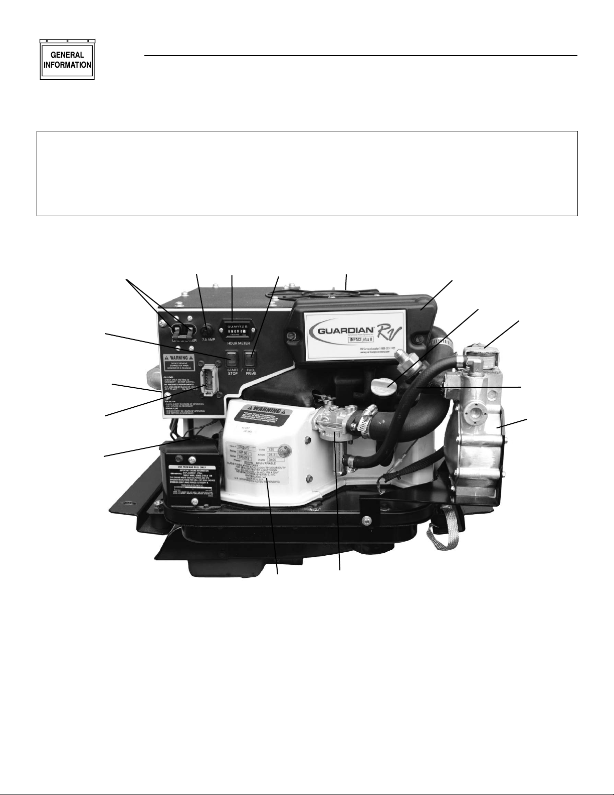
1.1 GENERATOR IDENTIFICATION
Please record the following information from the generator DATA DECAL or information decal,
located below the user control panel.
1. Model Number ____________________ 2. Serial Number __________________
3. kW Rating__________________________ 4. Rated Voltage __________________
5. Phase ______________________________ 6. Hertz __________________________
1.1.1 IMPACT-36LPG PLUS II FEATURES
◆
1. Generator Air Intake Screen
2. Air Cleaner
3. Air Intake Tube
4. LP Fuel Regulator
5. Oil Dipstick and Filler Tube
6. LP Carburetor
7. LP Fuel Solenoid
8. Fuel Primer Switch
9. Data Decal
10. 12 Volt Battery Connection
11. Engine Start/Stop Switch
12. Generator DC Output Leads
13. Circuit Breaker
14. Fuse
15. Hour Meter
16. Inverter Harness Connector
REFERENCE NUMBER IDENTIFICATION
1
2
3
4
5
6
7
8
9
10
11
12
13
14
15
16
Page 7

Generac®Power Systems, Inc. 5
Section 1 – General Information
IMPACT-36 plus II Recreational Vehicle Generator
1.1.2 INVERTER FEATURES (PART NO. 0D4885)
◆
1. Inverter
2. 12 Pin Connection
3. Customer AC Output
4. DC Input
5. Cooling Fan
REFERENCE NUMBER IDENTIFICATION
3
5
2
4
1
Page 8

6 Generac®Power Systems, Inc.
Section 1 – General Information
IMPACT-36 plus II Recreational Vehicle Generator
1.2 GENERATOR APPLICABILITY
These generators have been designed and manufactured for supplying electrical power for recreational
vehicles. Do not modify the generator or use it for any
application other than for what it was designed. If
there are questions pertaining to its application,
write or call the factory. Do not use the unit until
advised by a competent authority.
For fire safety, the generator must have been
properly installed in compliance with (1) ANSI
119.2-1975/NFPA 501C-1974 “Standard for
Recreational Vehicles”, Part III, “Installation of
Electrical Systems.” The generator also must
have been installed in strict compliance with
the manufacturer’s detailed installation
instructions. After installation, do nothing
that might render the unit in non-compliance
with such codes, standards and instructions.
This generator has been designed to work with an
inverter (P/N 0D4885). The inverter changes the voltage from the generator from a DC to an AC voltage.
This generator will not operate properly without the
inverter box connected. All repairs of the inverter
must be handled by an authorized service dealer (see
Page 12 in “Maintenance”).
Use this generator to supply electrical power for
operating 120 volts, single phase, 60 Hertz, electrical
loads. These loads can require up to 3400 watts (3.4
kW) for the Impact-36 plus II. The maximum current
at 120 volts is 28.3 amperes for the Impact-36 plus
II.
Do not overload the generator. Some installations may require that electrical loads be
alternated to avoid overloading. Applying
excessively high electrical loads may damage
the generator and may shorten its life. Add
up the rated watts of all electrical lighting,
appliance, tool and motor loads the generator
will power at one time. This total should not
be greater than the wattage capacity of the
generator. If an electrical device nameplate
gives only volts and amps, multiply volts
times amps to obtain watts (volts x amps =
watts). Some electric motors require more
amps of current for starting than for continuous operation.
1.3 SAFETY
Before using the generator set, carefully read GENERAL SAFETY RULES inside the cover. Comply with
these RULES to prevent accidents and damage to
equipment and/or property. Generac suggests copying and posting the GENERAL SAFETY RULES in
potential hazard areas of the recreational vehicle.
Safety should be stressed to all operators of this
equipment.
1.4 GENERATOR CONTROL PANEL
Mounted on the generator control panel (Figure 1.1)
are the following features:
Figure 1.1 — Typical Control Panel
1.4.1 FUEL PRIMER
Before starting a cold engine (if it has not been started in more than two weeks), press this switch to
bring fuel from the tank to the fuel carburetor. This
rocker type switch springs back into its original position when released.
1.4.2 START/STOP SWITCH
To crank and start the engine, hold this switch at its
START position. Release the switch when the engine
starts. To stop an operating engine, press and hold
the switch in its STOP position until the engine shuts
off. The switch center position is the RUN position.
1.4.3 FUSE
Protects the engine DC control circuit against electrical overload. If the fuse element has melted open due
to overloading, the engine cannot be cranked. If the
fuse must be replaced, use only an identical replacement fuse.
1.4.4 CIRCUIT BREAKERS
Protects generator's AC output circuit against
overload, i.e., prevents unit from exceeding
wattage/amperage capacity.
◆
◆
◆
◆
Circuit Breaker
Fuse
Start/Stop Switch
Fuel Primer
Hour Meter
DANGER
!
Page 9

Generac®Power Systems, Inc. 7
Section 2 – Operation
IMPACT-36 plus II Recreational Vehicle Generator
1.4.5 HOUR METER
Indicates the time the engine-generator has operated,
in hours and tenths of hours. Use the hourmeter
along with the periodic maintenance schedule for the
generator set.
1.5 ENGINE PROTECTIVE DEVICES
This generator has a computer that monitors low oil
pressure, oil temperature, engine speed, and low
voltage output. This section discusses those protective devices.
1.5.1 AUTOMATIC LOW OIL PRESSURE
SHUTDOWN
The engine is equipped with an oil pressure sensor
that shuts down the engine automatically when oil
pressure is too low. If the engine shuts down by itself
and the fuel tank has enough fuel, check the engine
oil level.
1.5.1.1 Initial Startup
During initial startup, a time delay built into the shutdown control system allows oil pressure to build. The
delay allows the engine to run for about 10 seconds
before sensing oil pressure.
1.5.1.2 Sensing low pressure
If the system senses low oil pressure during operation, the engine shuts down. If the engine has not
been restarted after a low oil pressure shutdown, and
the low oil level has not been corrected, the engine
runs for about 10 seconds as described above, then
stops.
1.5.2 HIGH TEMPERATURE SHUTDOWN
A temperature switch with normally-open (N.O.) contacts is mounted near the oil filter. If engine temperature were to exceed a preset temperature, the switch
contacts close and the engine shuts down.
1.5.3 OVERSPEED
If engine speed is increased manually (or otherwise)
beyond the control of the computer control system,
the computer disables the load capability of the generator and shuts down the engine.
Do not attempt to physically adjust or control
the engine speed. Equipment damage or personal injury may result.
1.5.4 LOW VOLTAGE
The computer monitors the voltage output of the generator. If voltage sensors indicate that voltage has
dropped below a preset level, the engine will automatically shut down. Once the unit has shutdown,
the computer is automatically reset when the engine
is restarted.
NOTE:
The computer allows for the low voltage output
that occurs during startup. A time delay that
allows the engine to start and warm up is programmed into the monitoring system.
Before restarting a generator that has been
shutdown, disconnect all loads the generator
might power by whatever means provided,
such as the recreational vehicle’s main circuit
breaker.
2.1 BEFORE STARTING THE ENGINE
IMPORTANT: INSTRUCTIONS AND INFORMATION
IN THIS MANUAL ASSUME THE GENERATOR HAS
BEEN PROPERLY INSTALLED, CONNECTED, SERVICED, TESTED AND ADJUSTED BY A QUALIFIED
INSTALLATION TECHNICIAN OR INSTALLATION
CONTRACTOR.
2.1.1 INSTALLATION
Generator installation must have been properly completed so it complies with all applicable codes, standards and regulations and with the manufacturer's
recommendations.
2.1.2 ENGINE LUBRICATION
Have engine crankcase properly serviced with recommended oil before starting. Refer to "Maintenance"
and "Specifications" sections for oil servicing procedures and recommendations.
Any attempt to crank or start the engine
before it has been properly serviced with the
recommended oil may result in engine failure.
2.1.3 FUEL SUPPLY
The engine must have adequate supply of proper fuel
to operate. Before starting, check that sufficient fuel
is available.
◆
!
◆
◆
!
◆
!
◆
◆
▼ ▼
◆
◆
Page 10

8 Generac®Power Systems, Inc.
Section 2 – Operation
IMPACT-36 plus II Recreational Vehicle Generator
2.1.4 COOLING AND VENTILATING AIR
Air inlet and outlet openings in the generator compartment must be open and unobstructed for continued proper operation. Without sufficient cooling and
ventilating air flow, the engine-generator quickly overheats, which causes it to automatically shutdown.
Overheating could also damage the unit or the vehicle.
2.1.5 ENGINE EXHAUST GAS
Before starting the generator engine, be sure there is
no way for exhaust gases to enter the vehicle interior
and endangering people or animals. Close windows,
doors and other openings in the vehicle that, if open,
might permit exhaust gases to enter the vehicle.
The generator engine releases DEADLY carbon
monoxide gas through its exhaust system. This
dangerous gas, if breathed in sufficient concentrations, can cause unconsciousness or even
death. Never operate the generator set with
the vehicle inside any garage or other enclosed
area. DO NOT OPERATE THE GENERATOR IF THE
EXHAUST SYSTEM IS LEAKING OR HAS BEEN
DAMAGED. SYMPTOMS OF CARBON MONOXIDE POISONING ARE (a) inability to think coherently, (b) nausea, (c) vomiting, (d) twitching
muscles, (e) throbbing temples, (f) dizziness, (g)
headaches, (h) weakness, and (i) sleepiness. IF
EXPERIENCING ANY OF THESE SYMPTOMS,
MOVE INTO FRESH AIR IMMEDIATELY. IF SYMPTOMS PERSIST, GET MEDICAL HELP. Shut down
the generator and do not operate it until it has
been inspected and repaired.
Never sleep in the vehicle while the genset is
running unless the vehicle has a working carbon
monoxide detector. The exhaust system must be
installed in accordance with the genset installation manual. Make sure there is ample fresh air
when operating the genset in a confined area.
2.2 STARTING THE GENERATOR
IMPORTANT: READ THE VEHICLE MANUFACTURER’S INSTRUCTIONS. THE OWNER/OPERATOR
SHOULD BECOME FAMILIAR WITH THE VEHICLE
IN WHICH THIS GENERATOR IS INSTALLED.
DIFFERENCES EXIST BETWEEN VEHICLES. FOR
EXAMPLE, SOME VEHICLES MAY USE A TRANSFER SWITCH TO ISOLATE DOCKSIDE POWER
FROM THE GENERATOR, WHILE OTHER VEHICLES MAY USE AN ISOLATING RECEPTACLE.
SOME VEHICLES MAY BE EQUIPPED WITH A DC
CONVERTER WHICH ALLOWS THE GENERATOR
TO POWER CERTAIN DC LIGHTING AND OTHER
DC LOADS.
To crank and start the generator engine, proceed as
follows:
1. Turn OFF electrical loads, using whatever means
provided in the vehicle (such as a main line circuit breaker or transfer switch).
NOTE:
If the engine is started with the start/stop switch
on the generator control panel, turn OFF loads by
setting the panel’s main breaker to its “OFF” or
“OPEN” position. Electrical load circuits may be
turned ON after the generator has started, stabilized and warmed up.
NOTE:
On gas units, use of the fuel primer is needed only
during the initial startup, after the unit has not
been used for an extended period of time (two
weeks) or the fuel line has been disconnected. The
primer is used to prime the fuel pump and carburetor.
2. To crank and start the engine, hold the start/stop
switch at START. Release the switch when the
engine starts.
If the engine does not start after it has been
cranking for 15 seconds, release the start/stop
switch and try again. Holding the switch for
longer than 15 seconds may damage the
starter motor.
3. Let the engine run at no-load for a few minutes to
stabilize and warm up the engine.
4. Turn ON electrical loads, using whatever means
provided (such as a main circuit breaker or
transfer switch).
NOTE:
If starting a warm generator engine, press the start
switch only slightly to engage the ignition system.
However, press and hold the starter switch for a
minimum of two (2) seconds to energize the field
boost system. If starting the engine without energizing the field boost system, the generator produces no output.
2.3 STOPPING THE GENERATOR
1. Turn OFF all electrical loads, using whatever
means provided (such as a main circuit breaker
or transfer switch).
2. Let the generator run at no-load for a few minutes, to stabilize internal engine-generator temperatures.
3. Hold Start/Stop switch in its STOP position.
!
◆
◆
DANGER
!
DANGER
!
Page 11

Generac®Power Systems, Inc. 9
Section 2 – Operation
IMPACT-36 plus II Recreational Vehicle Generator
2.4 APPLYING LOADS TO GENERATOR
When applying electrical loads to the generator,
observe these guidelines:
• Before applying electrical loads, let the generator
stabilize and warm up for a minute or two.
• DO NOT overload the generator.
2.4.1 LETTING ENGINE STABILIZE
The generator supplies correctly rated frequency and
voltage only at the proper governed speed. Some electrical appliances may be extremely sensitive to voltage and frequency. Incorrect frequencies and/or voltages can damage those appliances.
If electrical loads are applied at reduced operating
speeds, such loads imposed on the engine when sufficient power is not available may shorten engine life.
Never turn ON electrical loads until after the generator engine has started and stabilized ON-speed.
2.5 ATTENTION REQUIRED AFTER
SUBMERSION
If the motor home generator has been submerged in
water, it must NOT be started or operated. Following
any submersion in water, have an authorized
Generac Service Facility thoroughly clean and dry the
generator.
2.6 OPERATION IN HIGH GRASS OR
BRUSH
Never operate the generator while the vehicle is
parked in high grass, weeds, brush or leaves. Such
materials can ignite and burn from the heat of the
exhaust system. The generator exhaust system
becomes extremely hot during operation and remains
hot for a long time after it has shut down.
2.7 OPERATING PRECAUTIONS
Never operate the motor home generator set while the
vehicle is parked over dry leaves, dry grass or any
other combustible substance. The generator’s
exhaust system becomes extremely hot and can cause
a fire if it is too close to combustible materials.
2.8 FUEL REQUIREMENTS (LP UNITS)
These generators are equipped with a liquefied petroleum (LP) gas fuel system. LP gas is usually supplied
as a liquid in pressure tanks.
These generators require a “vapor withdrawal” type
fuel system. This type of gaseous fuel system uses the
vapors forming above the liquid fuel in the storage
tank. Air temperature around the storage tank must
be high enough to sustain adequate fuel vaporization.
In colder climates, use of an independent heat source
may be needed to be sure the fuel sufficiently vaporizes in the storage tank.
LP gas may consist of propane, butane or a mixture
of the two gases. Propane vaporizes at temperatures
as low as -20°F (-29°C), but butane returns to its liquid state when the temperature drops below about
32°F (0°C). For that reason, a higher ratio of propane
is desired in the gas mixture when temperatures
drop below freezing.
FUEL CONSUMPTION (IN GALLONS PER HOUR):
2.9 ENGINE OIL REQUIREMENTS
The recommended oils include the following:
• During summer months: SAE 30. An acceptable
substitute is SAE 10W-30.
• During winter months: SAE 5W30. DO NOT USE
SAE 10W-40.
Crankcase and oil filter capacity is about 950ml or
one (1) quart. Use no special additives. See
“Maintenance” section for oil level check and fill procedures.
2.10 LP GENERATOR SPECIFICATIONS
Model ..............................................Impact-36LPG plus II
Rated Maximum Continuous
AC Power Output ..............................3400 watts (3.4 kW)
Rated Voltage ................................................120 volts AC
Rated Maximum Continuous
Current at 120 volts................................28.3 AC amperes
Phase ............................................................Single Phase
Rated AC Frequency ................................................60 Hz.
Recommended Battery
Cranking Current ..............................................400 amps
Gross Weight ............................................................99 lbs
Maximum Cranking Current..............................250 Amps
Maximum Charging Current ..................................2 Amps
2.11 ENGINE SPECIFICATIONS
Type of Engine ......................................................GN-220
Cooling Method..................................................Air-cooled
Displacement............................................................220cc
Type of Governor ..............................................Electronic
Air Cleaner ..................................................Paper element
Starter ..................................................12 volt DC electric
Ignition System ................................................Solid state
Recommended Spark Plugs ................Champion RC14YC
Spark Plug Gap ..................................0.030 inch (0.8mm)
◆
LOAD LP
NO 0.20
HALF 0.41
FULL 0.77
Page 12

10 Generac®Power Systems, Inc.
Section 3 – Maintenance
IMPACT-36 plus II Recreational Vehicle Generator
3.1 MAINTENANCE
This section includes information about simple
maintenance which includes the following tasks:
• Checking engine oil level.
• Changing engine oil.
• Changing oil filter.
• Air cleaner maintenance.
• Cleaning the air intake screen.
Cleaning spark arrestor.
• Cleaning spark plug.
Replacing fuel filter.
Servicing inverter.
3.2 CHECKING ENGINE OIL LEVEL
Check engine crankcase oil level at least every eight
hours of operation, or before each use (Figure 3.1).
• Be sure the generator is as level as possible.
• Remove oil dipstick and wipe dry with clean, lintfree cloth.
• Install and tighten oil dipstick, then remove again.
• Oil should be at dipstick FULL mark. If necessary,
add the recommended oil to the FULL mark only.
DO NOT FILL ABOVE “FULL” MARK.
• Install and tighten oil dipstick cap before operating
the engine.
Figure 3.1 — Oil Dipstick and Fill Tube
NOTE:
See “Engine Oil Requirements”, Section 2.9 for
recommended oils.
3.3 CHANGE ENGINE OIL
Change engine oil after the first 25 hours of operation. Thereafter, change oil every 100 operating
hours. Change oil more frequently if operating consistently under heavy load or at high ambient temperatures.
• Warm up engine for at least five minutes, then shut
down.
• With engine still warm from running, clean area
around oil drain plug and remove oil drain plug
(Figure 3.2). Drain oil completely into a suitable
container.
• When oil has drained, install and tighten drain
plug.
• Remove oil dipstick and fill crankcase with the
recommended oil (See Page 11). The engine
crankcase can hold about 1 quart (950ml). DO
NOT FILL ABOVE “FULL” MARK.
• Install and tighten dipstick cap before operating
engine.
3.4 CHANGE OIL FILTER
Replace the engine oil filter after the first 25 hours of
operation, every 100 operating hours thereafter.
• Turn oil filter counterclockwise to remove (Figure
3.2).
Figure 3.2 — Oil Drain Plug and Engine Oil Filter
• Coat gasket of new filter with engine oil.
• Turn new filter clockwise until its gasket contacts
lightly with the filter adapter. Then tighten an additional 3/4 to one turn by hand.
• Run engine and check for leaks.
NOTE:
Check oil level and fill to full mark after checking
for leaks. Filter will retain some oil.
Oil Dipstick and Fill Tube
Page 13

Generac®Power Systems, Inc. 11
Section 3 – Maintenance
IMPACT-36 plus II Recreational Vehicle Generator
3.5 ENGINE AIR CLEANER
Paper Filter: Once every 25 operating hours or once
each year (whichever comes first), clean or replace
the paper filter (Figure 3.3). Follow the steps on page
12.
Figure 3.3 — Engine Air Cleaner Assembly
• Remove air cleaner cover, then remove paper filter.
• Clean air filter by gently tapping it on a solid surface. If the filter is too dirty, replace it with a new
one. Dispose of the old filter properly.
• Clean air cleaner cover then insert new paper filter
into cover and assemble to the base of the air
cleaner.
3.6 CLEAN AIR INTAKE SCREEN
Clean all foreign material from the air intake screen
(Figure 3.4) at lease once every 100 hours of operation. Clean more often if necessary.
Inspect the area around the generator exhaust muffler periodically and remove all grass, leaves, dirt,
etc. from this area.
Figure 3.4 — Clean Air Intake Screen
3.7 ENGINE SPARK PLUG
Clean engine spark plug and set gap to 0.030 inch
(0.76mm) every 100 hours of operation (Figure 3.5).
Clean by scraping or wire brushing and washing with
commercial solvent. DO NOT BLAST CLEAN SPARK
PLUG.
Figure 3.5 — Setting Gap on Spark Plug
Sparking can occur if wire terminal does not
fit firmly over spark plug terminal end. If necessary, reform wire terminal to obtain a tight
fit.
3.8 INVERTER
All repairs of the inverter must be handled by an
authorized service dealer (see Figure 3.7).
Figure 3.7 — Inverter Warning Label
3.9 CLEANING THE GENERATOR
Keep the generator set as clean and dry as possible.
Dirt and moisture that are permitted to accumulate
on electrical windings have an adverse affect on the
insulation resistance of those windings.
Moisture that is allowed to remain in contact with
windings will be retained in voids and cracks of the
windings. Dirt makes the problem worse, since it
tends to hold the moisture into contact with the
windings. Salt, as from sea air, worsens the problem
since it tends to absorb moisture from the air. The
combination of salt and moisture makes a good electrical conductor.
!
Air Intake Screen
Page 14
12 Generac®Power Systems, Inc.
Section 3 – Maintenance
IMPACT-36 plus II Recreational Vehicle Generator
Do NOT use a forceful spray of water to clean
the generator. Water will enter the generator
interior and cause problems, and may also
contaminate the generator fuel system.
3.10 BATTERY
All lead-acid storage batteries will discharge when
not in use. Inspect the generator battery as follows:
3.10.1 ONCE WEEKLY
Inspect battery posts and cables for tightness, corrosion. Clean and/or tighten as necessary.
Also check battery fluid level, and, if necessary, fill
with DISTILLED WATER ONLY. DO NOT USE TAP
WATER IN BATTERY.
3.10.2 EVERY SIX MONTHS
Have the battery state of charge and condition
checked by an automotive service facility. This should
be done with an automotive type battery hydrometer.
Storage batteries give off explosive hydrogen
gas. This can form an explosive mixture
around the battery for several hours after
charging. The slightest spark can ignite the
gas and cause an explosion. Such an explosion can shatter the battery and cause blindness or other injury. Any area that houses a
storage battery must be properly ventilated.
Do not allow smoking, open flame, sparks or
any spark producing tools or equipment near
the battery.
Battery electrolyte fluid is an extremely caustic sulfuric acid solution that can cause severe
burns. Do not permit fluid to contact eyes,
skin, clothing, painted surfaces, etc. Wear protective goggles, protective clothing and
gloves when handling a battery. If fluid is
spilled, flush the affected area immediately
with clear water.
Do not use any jumper cables or booster battery to crank and start the generator engine.
If any battery has discharged, remove it from
the vehicle for recharging.
3.11 SERVICE AND ADJUSTMENTS
3.11.1 ENGINE SPEED
Engine speed is completely computer-controlled.
There is no adjustment for speed on the unit. The
computer adjusts the engine speed using an electronic governor throttle control. The computer monitors
the demand for power and adjusts the engine speed
accordingly. This allows the engine to produce only
the power required, resulting in fuel economy as well
as lowering the overall noise emitted.
NOTE:
The computer will disable the electrical load
capabilities of the generator and enter a fault condition if the throttle is accelerated manually or
any other way.
3.12 ADJUSTING THE CARBURETOR
The carburetor of the generator is preset at the factory. The carburetor should not be tampered with, as
this will void the emission control system warranty. If
the generator is used at altitudes in excess of 5,000
feet, consult the Generac Authorized Service Facility
regarding high altitude jetting changes.
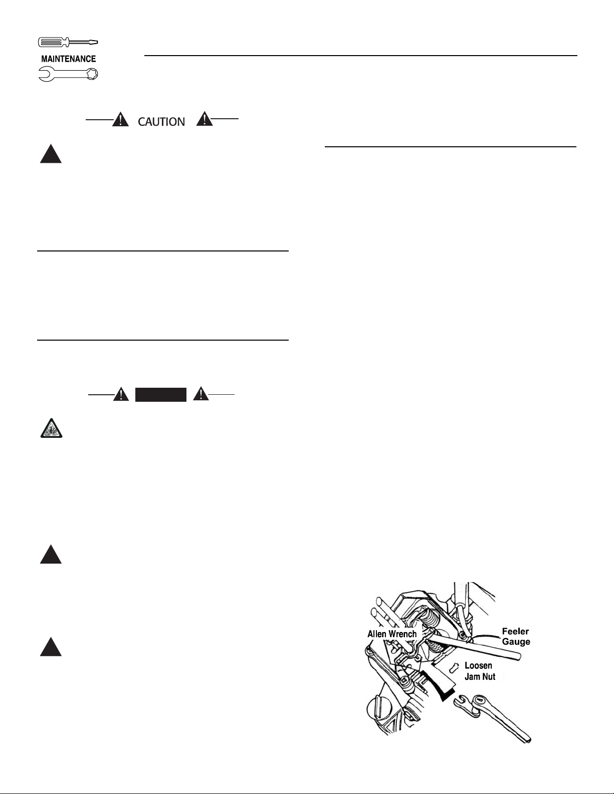
3.13 ADJUSTING VALVE CLEARANCE
After the first 50 hours of operation, adjust the valve
clearance in the engine.
When adjusting valve clearance, the engine should be
at room temperature and the piston should be at Top
Dead Center (TDC) of its compression stroke (both
valves closed). Correct clearance is 0.001-0.003 inch
(0.03-0.07mm). Adjust valve clearance as follows:
1. Loosen the rocker arm jam nut. Use an allen
wrench to turn the pivot ball stud while checking
clearance between the rocker arm and the valve
stem with a feeler gauge (Figure 3.8).
Figure 3.8 — Adjusting Valve Clearance
◆
!
!
◆
◆
!
DANGER
Page 15

Generac®Power Systems, Inc. 13
Section 3 – Maintenance
IMPACT-36 plus II Recreational Vehicle Generator
2. When valve clearance is correct, hold the pivot
ball stud with the allen wrench and tighten the
rocker arm jam nut with a crows foot. Tighten the
jam nut to 65-85 inch-pounds torque. After tightening the jam nut, recheck valve clearance to
make sure it did not change (Figure 3.9).
Figure 3.9 — Tightening Jam Nut
3.14 MAJOR SERVICE MANUAL
To obtain a service manual for the generator, order it
from the dealer/distributor. Be sure to identify the
unit’s MODEL NUMBER and SERIAL NUMBER.
3.15 EXERCISING THE GENERATOR
Generac recommends that the generator is started
and operated at least once every seven days. Let the
unit run for at least 30 minutes to “exercise” the
engine.
3.16 OUT OF SERVICE PROTECTION
If the generator cannot be exercised every seven days,
and it is to be out of service longer than 30 days, prepare the generator for storage as follows:
• Start the engine and let it warm up.
• While the engine is still warm from running, drain
the oil completely. Refill crankcase with recommended oil. See “Specifications.”
• Attach a tag to the engine indicating the viscosity
and classification of the oil in the crankcase.
• Remove spark plug and add about 1/2 ounce
(15ml) of clean, fresh engine oil into spark plug
threaded opening. Crank engine several times to
distribute oil, then install and tighten spark plug.
• Remove the battery and store in a cool, dry room
on a wooden board. Never store the battery on any
concrete or earthen floor.
• Clean and wipe the entire generator.
3.17 RETURN UNIT TO SERVICE AFTER
STORAGE
To return the unit to service after storage, proceed as
follows:
• Check tag on engine for oil viscosity and classification. Verify that the correct recommended oil is
used in engine. If necessary, drain and refill with
proper oil.
• Check battery. Fill all cells to the proper level with
distilled water. DO NOT USE TAP WATER IN THE
BATTERY. Recharge battery to 100% state of
charge, or, if defective, replace the battery.
• Turn OFF all electrical loads, then start the engine.
• Let engine warm up.
• Apply electrical loads up to at least 50% of the
unit’s rated wattage capacity.
• When engine is thoroughly warmed up, shut it
down.
THE GENERATOR IS NOW READY FOR SERVICE.
Page 16

14 Generac®Power Systems, Inc.
Section 4 – Notes
IMPACT-36 plus II Recreational Vehicle Generator
Page 17

PART II –
INSTALLATION
INSTRUCTIONS
ONLY QUALIFIED ELECTRICIANS OR CONTRACTORS
SHOULD ATTEMPT INSTALLATION!!
DANGER
Page 18

16 Generac®Power Systems, Inc.
Safety Rules
IMPACT-36 plus II Recreational Vehicle Generator
NOTICE TO INSTALLER
These Installation Instructions have been published
by Generac to aid in the installation of the products
described in this manual. Generac assumes that
installation personnel are familiar with the procedures
for installing such products, or similar products that
Generac manufactures. Generac also assumes that
personnel have been trained in the recommended
installation procedures for these products and that
such training includes (a) use of common hand tools,
(b) use of special Generac tools, and (c) use of any
tools and/or equipment from other suppliers.
Generac cannot possibly know of, nor advise the
recreational vehicle trade of, all conceivable methods,
procedures, or techniques by which to perform an
installation. Nor can Generac anticipate every possible hazard that might result from each installation
method, procedure, or technique. Generac has not
undertaken any such wide evaluation. Therefore,
people who use a method, procedure, or technique
that Generac does not specifically recommend must
first completely satisfy themselves that their safety,
the safety of the vehicle's occupants, and the product's safety are not endangered by the method, procedure, or technique selected.
Information, illustrations, specifications, etc., contained in these Installation Instructions are based on
the latest information available at the time of publication. Every effort has been expended to be sure that
such data are both accurate and current. However,
the manufacturer reserves the right to change, alter,
or otherwise improve this product at any time, without prior notice.
Despite the safe design of this generator,
operating this equipment imprudently, neglecting
its maintenance, or being careless can cause
possible injury or death. Permit only responsible
and capable persons to operate or maintain this
equipment.
Parts of the generator are rotating and/or hot
during operation. Exercise care near running
generators.
Potentially lethal voltages are generated by
these machines. Ensure all steps are taken to
render the machine safe before attempting to
work on the generator.
GENERAL HA
ZARDS
• For safety reasons, Generac recommends that the
installation, initial startup, and maintenance of
this equipment is carried out by a Generac
Authorized Service Dealer.
• The engine exhaust fumes contain carbon monoxide, which can be DEADLY. This dangerous gas, if
breathed in sufficient concentrations, can cause
unconsciousness or even death. This exhaust system must be installed properly, in strict compliance with applicable codes and standards.
Following installation, do nothing that might render the system unsafe or in noncompliance with
such codes and standards. The generator compartment must be completely vapor-sealed from
the vehicle interior. There must be no possibility of
exhaust fumes entering the vehicle interior. Never
operate this equipment with a leaking or defective
exhaust system.
• Keep hands, feet, clothing, etc., away from drive
belts, fans, and other moving or hot parts.
Never remove any drive belt or fan guard while
the unit is operating.
• Adequate, unobstructed flow of cooling and ventilating air is critical to correct generator operation and is required to expel toxic fumes and
fuel vapors from the generator compartment.
Without sufficient cooling airflow, the
engine/generator quickly overheats, which causes serious damage to the generator. Do not alter
the installation or permit even partial blockage
of ventilation provisions, as this can seriously
affect safe operation of the generator.
• When working on this equipment, remain alert at
all times. Never work on the equipment when
physically or mentally fatigued.
• Before performing any maintenance on the generator, disconnect its battery cables to prevent accidental startup. First, disconnect the cable from the
battery post, indicated by a NEGATIVE, NEG, or
(–). Reconnect that cable last.
• Never use the generator or any of its parts as a
step. Stepping on the unit can stress and break
parts, and may result in dangerous operating conditions from leaking exhaust gases, fuel leakage,
oil leakage, etc.
• Never insert any tool or other object through openings in the generator interior, even if the unit is not
running. Seriouse injury or damage to the equipment may occur.
!
!
DANGER: For fire safety, installation of a generator into a recreational vehicle must comply
strictly with NFPA 70 (latest edition), “National Electrical Code”, Article 551, and NFPA 1192
(latest edition), “Standard for Recreational Vehicles”. In addition, installation must comply with
the manufacturer’s instructions and recommendations.
!
!
DANGER
!
!
Page 19

Generac®Power Systems, Inc. 17
ELECTRICAL HAZARDS
• The generator covered by this manual produces
dangerous electrical voltages that can cause fatal
electrical shock. Avoid contact with bare wires, terminals, connections, etc., while the unit is running.
Ensure all appropriate covers, guards, and barriers are in place before operating the generator. If
work must be done around an operating unit,
stand on an insulated, dry surface to reduce shock
hazard.
• Do not handle any kind of electrical device while
standing in water, while barefoot, or while hands
or feet are wet. DANGEROUS ELECTRICAL
SHOCK MAY RESULT.
• During installation onto the vehicle, properly
ground (bond) the generator either by solid mounting to the vehicle frame or chassis, or by means of
an approved bonding conductor. DO NOT connect
the bonding conductor to any generator part that
might be removed or disassembled during routine
maintenance. If the grounding conductor must be
replaced, use only a flexible conductor that is of
No. 8 American Wire Gauge (AWG) copper wire
minimum.
• If the vehicle electrical circuits can be powered by
any other source of electricity (such as, a “dockside”
power receptacle), there must be no possibility of
connecting the different power sources to the vehicle’s circuits at the same time. The dockside (utility)
power source must be positively isolated from the
vehicle’s circuits whenever the generator is operating. Failure to isolate the vehicle’s circuits from the
dockside power supply when the generator is running may result in damage to the generator or in
serious injury or death to dockside (utility) power
workers due to backfeed of electrical energy.
• In case of an accident caused by electric shock,
immediately shut down the source of electrical
power. If this is not possible, attempt to free the
victim from the live conductor. AVOID DIRECT
CONTACT WITH THE VICTIM. Use a nonconducting implement, such as, a rope or board, to
free the victim from the live conductor. If the victim is unconscious, apply first aid, and get
immediate medical help.
• Never wear jewelry when working on this equipment. Jewelry can conduct electricity, resulting in
electric shock, or may get caught in moving components, causing injury.
FIRE HAZARDS
• For fire safety, the generator must be installed
and maintained properly. Installation always
must comply with applicable codes, standards,
laws, and regulations. Adhere strictly to local,
state and national electrical and building codes.
Comply with regulations the Occupational Safety
and Health Administration (OSHA) has established. Also, ensure that the generator is
installed in accordance with the manufacturer’s
instructions and recommendations. Following
proper installation, do nothing that might alter a
safe installation and render the unit in noncompliance with the aforementioned codes, standards, laws, and regulations.
• Keep a fire extinguisher in the vehicle at all times.
Extinguishers rated “ABC” by the National Fire
Protection Association are appropriate for use on
the recreational vehicle generator electrical system.
Keep the extinguisher properly charged, and be
familiar with its use. If there are any questions pertaining to fire extinguishers, consult the local fire
department.
EXPLOSION HAZARDS
• Do not smoke around the generator. Wipe up any
fuel or oil spills immediately. Ensure that no combustible materials are left in the generator compartment, or on or near the generator, as FIRE or
EXPLOSION may result. Keep the area surrounding the generator clean and free from debris.
• All fuel types are potentially FLAMMABLE and/or
EXPLOSIVE and should be handled with care.
Comply with all laws regulating the storage and handling of fuels.
• Fuel supply lines must be properly installed, purged
and leak-tested according to applicable fuel-gas
codes, before placing this equipment into service.
There must be no possibility of fuel vapors entering the vehicle interior.
• It is required to install an approved, flexible, nonconductive fuel line between the generator fuel connection point and the rigid fuel lines.
Safety Rules
IMPACT-36 plus II Recreational Vehicle Generator
Page 20

18 Generac®Power Systems, Inc.
1.1 PURPOSE AND SCOPE
OF THE MANUAL
These Installation Instructions have been prepared
especially for the purpose of familiarizing installers
and owners of the applicable equipment with the
product's installation requirements. Give serious
consideration to all information and instructions in
the manual, both for safety and for continued reliable
operation of the equipment.
Because of the different recreational vehicle models
and the variations between the models, it would be
extremely difficult, if not impractical, to provide
detailed instructions for every possible installation.
For that reason, instructions and illustrations in this
manual are general in nature. Illustrations are not
intended to serve as detailed installation blueprints.
The installation should comply strictly with all
applicable codes, standards, and regulations pertaining to the installation and use of this product. If any
portion of this manual appears to be in conflict with
such codes, standards, or regulations, the applicable
codes, standards, or regulations must take precedence over the manual.
1.2 SAFETY
Before handling, installing, operating, or servicing
this equipment, carefully read the “Notice to
Installer” and “Safety Rules” on Pages 18 and 19.
Comply with all safety rules to prevent death, personal injury, or damage to equipment and/or property. Stress safety to all installers, operators, and service technicians who work on this equipment.
1.3 STANDARDS BOOKLETS
Installation, use, and servicing of this equipment
should comply strictly with published standards, as
well as the manufacturer's recommendations. The
following standards booklets (latest revision) are
available from the sources indicated:
1. NFPA 1192, “Standard for Recreational Vehicles”
(replaces ANSI A119.2/NFPA 501C), available
from the National Fire Protection Association,
Batterymarch Park, Quincy, MA 02269.
2. NFPA 70, “NFPA Handbook of the National
Electric Code,” available same as Item 1.
3. ANSI/RVIA EGS-1, “Engine Generator Sets for
Recreational Vehicle Safety Requirements”, avaialable from the Recreational Vehicle Industry
Association, 1896 Preston White Drive, Reston,
VA 22090.
4. California Administrative Code, Title 25, available from the State of California, Documents
Section, P.O. Box 1015, North Highlands,
CA 95660.
5. CSA Electrical Bulletin 946, available from the
Canadian Standards Association, Housing and
Constructions Materials Section, 178 Rexdale
Boulevard, Rexdale, Ontario, Canada, M9W 1R3.
1.4 EQUIPMENT DESCRIPTION
Instructions and information in this section pertain
to Generac Impact air-cooled generators — more
specifically, the installation of Impact-34 plus II and
IMPACT-36 plus II Recreational Vehicle Generators.
These generators are designed specifically for
installing in recreational vehicles.
1.5 ENGINE GENERATOR OPERATING
SPEED
The generators are driven by gasoline-powered, single-cylinder engines. The engines drive revolving
fields (rotors), high frequency, permanent magnet
alternators. The generators supply 120 volts AC at 60
Hertz with DC inverter. The generators revolving
fields are driven at a variable speed depending on the
demand for power. Computers monitor that demand
and adjust the engine speed to provide adequate
power to the connected loads.
Section 1 – General Information
IMPACT-36 plus II Recreational Vehicle Generator
Page 21

Generac®Power Systems, Inc. 19
Section 2 – Installation
IMPACT-36 plus II Recreational Vehicle Generator
2.1 LOCATION AND SUPPORT
2.1.1 GENERATOR LOCATION
The most desirable location for the generator set is
between the vehicle's main frame members However,
this is seldom possible. Most units must be installed
on the side of the vehicle and are difficult to reinforce.
Many recreational vehicles have been factory
equipped with an area for the generator set. Some
vehicles may even have a generator compartment,
provided by the vehicle manufacturer.
Plan the generator location based on the following:
• The generator set must be installed on a framework
that is part of the recreational vehicle, as outlined in
the paragraph entitled “Generator Support.”
• The location must provide an access opening that
is large enough to permit generator removal
(unless the generator is to be removed from underneath the supporting framework.
• The location must provide easy access to frequently
serviced components, such as filters, oil drains,
spark plugs and other common maintenance parts.
• The location must provide sufficient room to allow
minimum clearance of at least 1 inch between all
sides and 1-1/2 inches on top of the generator. If
sound insulation is to be used on compartment
walls and ceiling, the minimum recommended
applies to the space between the generator and
such insulation.
• The location must provide adequate cooling and
ventilating air flow for the generator without a
great deal of work and expense.
2.1.2 GENERATOR SUPPORT
The generator must be securely attached to a metal
framework that has been made part of the vehicle
frame structure by bolting or welding. The metal
framework on which the generator will rest and
which will restrain the generator set should consist of
at least two horizontal beams. These beams should
consist of (a) 1-1/2 inch square, 11 gauge steel tubing
OR (b) 1-1/2 inch, 11 gauge angle iron. A typical supporting frame with horizontal support tubing, is
shown in Figure 2.1.
The generator can be installed so that it sits on top of
the horizontal support tubing, if the vehicle design
permits. Another method is to suspend the generator
below the horizontal support tubing by means of suitable, structurally sound metal framework. The following general rules apply:
• Vehicle construction MUST be capable of supporting the weight of the generator.
• Whether the generator is mounted above the horizontal support tubing or suspended below the tubing, the supporting frame used must be structurally sound.
• If the generator cannot be bolted directly to the
supporting frame or support tubing, consider
using additional tubing, angle brackets or other
supports to give the supporting frame sufficient
strength.
Figure 2.1 —Typical Horizontal Support Frame
2.1.3 SUSPENDED MOUNTING
If the generator will be suspended below the horizontal support tubing, the suspension method used with
the vehicle frame members must have the following:
(a) be able to support the weight of the generator; and
(b) provide sufficient restraint for the generator. One
typical suspended mounting system is shown in
Figure 2.2. The location of a suspended mounting
system must be carefully planned, keeping the following general rules in mind:
• Protect the generator against road splash and
debris. Baffles or splash guards may be required
to protect certain areas of the generator. To make
sure the generator is adequately protected, road
test the installation through mud, water and slush.
Figure 2.2 — Typical Suspended Mounting
System
• The installer must make certain that selected location will permit adequate cooling and ventilating
air flow to be supplied.
◆
◆
◆
Page 22

20 Generac®Power Systems, Inc.
Section 2 – Installation
IMPACT-36 plus II Recreational Vehicle Generator
2.1.4 GENERATOR RESTRAINT
Use four 5/16"-18 hardened steel bolts (Grade 5) to
fasten the generator to the supporting frame or the
support tubing. These bolts must pass through (a)
the generator mounting base, (b) the compartment
floor, if a compartment is used, and (c) the supporting framework (Figure 2.3). All bolts must be long
enough so that when tight, at least 3 threads are visible past the retaining lock nuts. Refer to “COMPARTMENT” section for location of generator mounting holes.
Figure 2.3 — Typical Generator Restraint
2.2 GENERATOR COMPARTMENTS
The generator set may or may not be installed inside
a compartment that is constructed specifically for
housing a generator. This section applies to generator
compartments when they are installed. The following
general rules apply to compartments:
• The generator compartment should be either constructed of, or lined with, 26 gauge galvanized
steel.
IMPORTANT: ALUMINUM IS NOT AN ACCEPTABLE
ALTERNATIVE TO GALVANIZED STEEL, DUE TO
ALUMINUM'S LOW MELTING POINT.
• If the compartment is lined with galvanized steel, it
may be constructed of any material. Generac recommends that the compartment be constructed of
1/2-inch thick plywood, with the floor made of a
double thickness of plywood for added strength.
• All seams, splices and joints of the compartment
walls (unless vapor tight by design) should be
caulked.
IMPORTANT: CAULKING MUST BE DONE SO THAT
THE CAULKING MATERIAL WILL STAY IN PLACE
PERMANENTLY. PRESSING SUCH MATERIALS AS
PUTTY TAPE ONTO JOINTS AND SEAMS WILL NOT
MEET THAT REQUIREMENT. A HIGH QUALITY SILICONE RUBBER SEALANT IS RECOMMENDED.
• Holes and openings through the compartment
walls for passage of electrical conduit, conductors,
etc, into vehicle living area must be sealed vaportight with silicone rubber base sealant.
• If using flexible metal conduit, seal the conduit at
the end where it terminates inside the junction
box. Flexible metal conduit is NOT vapor tight
along its entire length.
• Seams and joints of the galvanized steel (whether
used as a liner or the compartment itself) must be
lapped and mechanically secured. Such seams
may be manufactured, welded, bolted, riveted, or
screwed. Manufactured lock seams are shown in
Figure 2.4.
◆
Figure 2.4 — Types of Lock Seams
Page 23

Generac®Power Systems, Inc. 21
Section 2 – Installation
IMPACT-36 plus II Recreational Vehicle Generator
2.2.1 COMPARTMENT SIZE
Plan the compartment size carefully. Provide a minimum of at least 1 inch (2” recommended) of clearance between the generator and compartment walls
and 1 inch (2” recommended) of clearance between
the generator and the ceiling AFTER the compartment has been lined with metal, and AFTER sound
insulation has been installed (Figure 2.5).
NOTE:
Refer to the “Major Features and Dimensions”
drawing in the back of this manual.
Figure 2.5 — Provide Clearance Around
Generator
2.2.2 COMPARTMENT CONSTRUCTION
• The generator compartment should be constructed
of 1/2 inch thick plywood. Make the compartment
floor a double thickness of 1/2 inch plywood with
the grain of the wood at cross section for added
strength (Figure 2.6).
Figure 2.6 — Typical Compartment Construction
• Line the entire compartment interior with 26 gauge
galvanized steel as described above.
• Line the exterior (underside) of the compartment
floor with 26 gauge galvanized steel.
• Vapor seal all compartment seams and joints, to
prevent poisonous, flammable or explosive vapors
from entering the vehicle interior. Refer to the
sealant information as noted previously.
NOTE:
Silicone rubber base sealant is an acceptable
caulking material. Pressing putty tape onto compartment joints and seams is NOT acceptable.
• After the compartment has been metal lined and
vapor sealed, line the compartment interior walls
and ceiling with an approved, non-flammable
sound insulating material. See “Sound Insulating
Materials.”
Do not install sound insulation or any
absorbent material on the compartment floor
interior. Such materials will become soaked
with combustible or explosive vapors and liquids and will become a fire hazard.
• Openings in compartment walls for passage of electrical conduit, conductors, hoses, cables, etc.,
must be made vapor tight with suitable caulking
material.
• Flexible conduit must be sealed internally at the
end where it terminates inside a compartment's
electrical junction box.
NOTE:
The preceding is required because flexible conduit, due to its unique construction, is not vaportight along its entire length.
Do not install any flammable material directly
above or around the compartment. Heat,
transferred through the compartment structure, may be sufficient to ignite, char or discolor seat cushions, fiberboard and other
flammable materials. Use approved non-flammable insulating materials in high temperature areas.
◆
◆
DANGER
DANGER
Page 24

22 Generac®Power Systems, Inc.
Section 2 – Installation
IMPACT-36 plus II Recreational Vehicle Generator
2.2.3 SOUND INSULATING MATERIALS
Once installers have determined that compartments
are properly constructed and metal lined, they can
add acoustical material. This may include additional
sealant or insulating material, to reflect noise away
from the vehicle interior.
Sound insulating materials should be of a non-flammable type. One excellent insulating material is a 1
inch thick fiberglass having a 2-pound density. When
fiberglass is used, its coated side should face toward
the compartment interior.
Using a combination of sound insulating materials
can often reduce noise more effectively than a single
material. For example, a sheet of lead or visco-elastic
material, along with a layer of other acoustical material, is more effective than when a single material is
used.
2.2.4 COMPARTMENT FLOOR CUTOUTS
Provide openings in the generator compartment for
the following items (Figure 2.7):
• Engine exhaust and cooling air outlets
• Generator cooling air inlet
• Four holes for passage of generator mounting
bolts. See “Generator Restraint” on Page 19.
Fuel lines and exhaust piping must not penetrate into vehicle living area.
!
◆◆
Figure 2.7 – Compartment Floor Cutout (0A6203-A)
DANGER
Page 25
Generac®Power Systems, Inc. 23
Section 2 – Installation
IMPACT-36 plus II Recreational Vehicle Generator
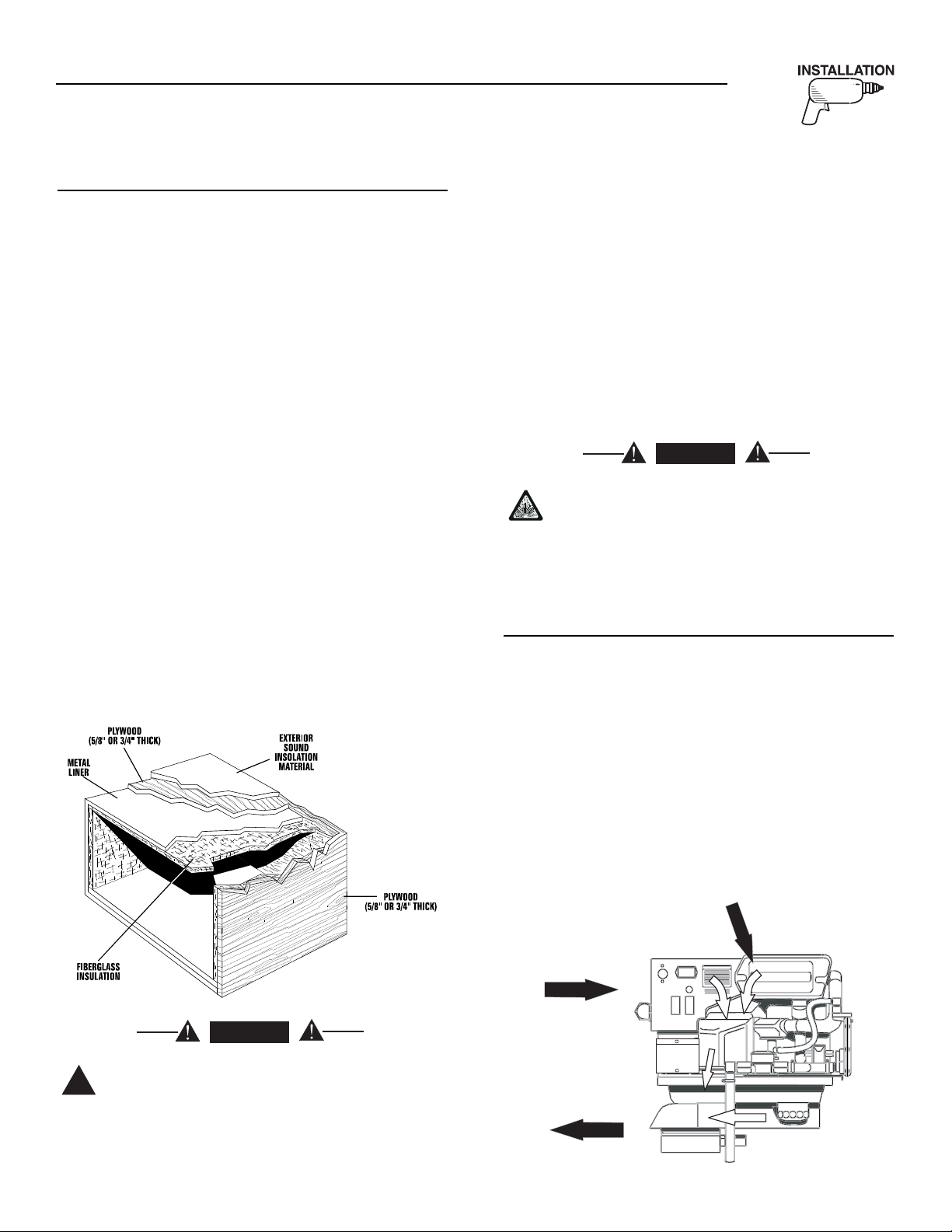
2.2.5 ACOUSTICS
If excessive noise levels should become a problem,
the installer may wish to consider the following:
• Using special sound insulating materials.
• Construction of a special noise abatement compartment.
IMPORTANT: ANY METHOD USED TO REDUCE
NOISE MUST NOT ADVERSELY AFFECT THE
FLOW OF COOLING AND VENTILATING AIR INTO
OR OUT OF THE COMPARTMENT.
In addition to the effective use of sound insulating
materials, construction of a special noise abatement
compartment might be considered to reduce noise
levels. Such a compartment might be constructed as
follows (Figure 2.8):
• Use 5/8-inch thick or 3/4-inch thick plywood in the
compartment.
• Construct the compartment floor of a double thickness of 5/8-inch or 3/4-inch plywood.
• Line the compartment interior walls and floor, as
well as the underside of the floor, with 26-gauge
galvanized steel.
• Vapor seal all compartment seams and joints.
• Over the galvanized steel lining, install a selected
combination of acoustical materials as mentioned
in “Sound Insulating Materials.”
Figure 2.8 — Typical Noise Abatement
Compartment
Do not install any insulation or other
absorbent materials on the interior or underside of the compartment floor.
• Seal all compartment door edges to prevent noise
leakage around the door perimeter.
• Line the compartment door interior (except for air
openings) with suitable, fire proof sound insulation (such as 1-inch thick fiberglass with a 2pound density).
It is absolutely essential that an adequate flow of air
for cooling, ventilating and engine combustion be
supplied to the generator set. Without sufficient air
flow, the engine-generator quickly overheats. Such
overheating can cause serious operating difficulties
and may also cause fire and personal injury. The
installer must make sure that sufficient air is available to the generator for cooling, ventilating and combustion. The installer must also provide for a path
for exhausting the cooling air to the exterior of a compartment, if so equipped.
Never use discharged cooling air for heating
or permit such air to enter the vehicle interior.
This air contains deadly carbon monoxide gas
and other poisonous, flammable or explosive
gases.
2.3 COOLING AND VENTILATING AIR
2.3.1 GENERATOR AIR FLOW
Engine operation drives cooling fans for the 2-stage
cooling air system. A pressure fan draws cooling air
into the top of generator and into the side of the control panel (Figure 2.9). This air flow cools the enginegenerator and electronic components. The second
part of the cooling system, a suction fan, draws air
that is heated from a hot engine into a collector pan
at the base of the unit. This heated air (although cooler than exhaust muffler) is directed across the muffler to cool it. The heated air flow is then deflected out
the bottom toward the ground.
Figure 2.9 — Air Flow Through Engine-
Generator
◆
◆
DANGER
DANGER
!
Page 26

24 Generac®Power Systems, Inc.
Section 2 – Installation
IMPACT-36 plus II Recreational Vehicle Generator
2.3.2 COOLING AIR INLET OPENINGS
Provide three air inlet openings, whether the generator is housed in a conventional compartment or not.
Two of the openings should be 10 square inches and
located as shown in Figure 2.10. The third opening
should provide for a minimum of 40 square inches
unrestricted and be located lower on the compartment door.
NOTE:
Screening, louvers, or expanded metal that cover
air openings restrict air flow that must be compensated for by making the actual air opening proportionately larger. See “Compensating for
Restrictions.”
For conventional compartment mounted units, the
air inlet is generally provided in the compartment
door.
Figure 2.10 — Air Inlet in Compartment Door
IMPORTANT: IF PLANNING TO INSTALL THE GENERATOR IN A COMPARTMENT, BE SURE TO LEAVE
AT LEAST ONE INCH (2” recommended) OF CLEARANCE BETWEEN THE GENERATOR AND COMPARTMENT WALLS AND CEILING. INCLUDE 26
GAUGE GALVANIZED STEEL LINING AND SOUND
INSULATION WHEN MEASURING FOR THIS 1 INCH
(2” recommended) CLEARANCE.
When the unit is installed on a suspended mounting
system, one of several different methods of supplying
air flow may be used as follows:
• Provide a door in the vehicle skirt having an air
inlet opening (Figure 2.11).
Figure 2.11 — Suspended Mount Inlet Door
• Using ductwork (Figure 2.12). The installer must
be sure air is available to the top of the generator
since air inlets are located at the top.
Figure 2.12 — Air Inlet Using Ductwork
• By providing an opening in the vehicle skirt and
space above the generator for cooling air flow
(Figure 2.13). Recommended clearance above the
top of the generator is at least 2 inches.
Figure 2.13 — Air Inlet in Vehicle Skirt
◆
10 Square Inches
(Optional Openings)
40 Square Inches
(Minimum Opening)
Page 27
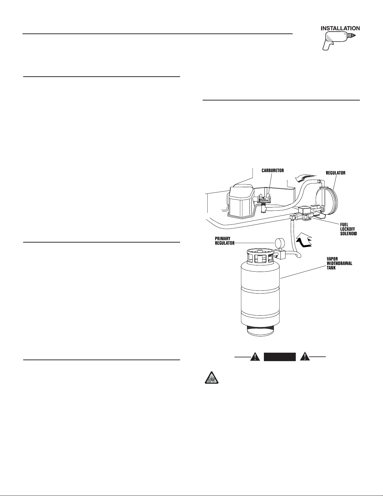
Generac®Power Systems, Inc. 25
Section 2 – Installation
IMPACT-36 plus II Recreational Vehicle Generator
2.3.3 COMPENSATING FOR RESTRICTIONS
Such materials as screening, louvers, or expanded
metal can restrict the free flow of air. Compensate for
this restriction by making the actual air opening proportionately larger.
Some materials may offer only a 60 percent “free air
inlet area.” Other more efficient materials may provide up to a 90 percent free air inlet area. The percentage of free air inlet opening is usually available
from the material supplier or manufacturer.
TO DETERMINE THE ACTUAL AIR INLET OPENING SIZE REQUIRED, DIVIDE 40 SQUARE INCHES BY THE PERCENTAGE OF FREE AIR INLET
AREA FOR THE MATERIAL USED.
For example: If planning to use screening with an
80% free air inlet area, divide 40 by 0.8, which
results in 50 square inches. Minimum actual size of
air inlet opening in this case is 50 square inches. An
opening that measures 4 inches wide by 12-1/2 inches long provides the required air flow (4 x 12.5 = 50
square inches).
2.3.4 INVERTER LOCATION
The inverter should be located in a dry, well ventilated area in order for the inverter to work effectively.
Approximately eight inches of space should be
allowed at each end of the inverter for adequate ventilation. IT SHOULD NOT BE LOCATED IN THE
SAME COMPARTMENT AS THE GENERATOR.
The sensing harnesses supplied with the inverter
have a maximum length of 12 feet. If the cables are
longer than needed, coil the excess near the inverter
unit. If a greater length is needed, contact Generac.
DO NOT ATTEMPT TO SHORTEN OR LENGTHEN
THE SUPPLIED sensing harnesses. The DC power
wires may be cut to the required length. Allow enough
length to make connection. Coil excess inside J-Box.
2.3.5 TESTING THE INSTALLATION
Generac recommends testing the installation to be
sure adequate cooling air flow is available to the unit
before placing the unit into service. If the unit shows
signs of overheating, enlarge the air openings. Never
place a unit into service until absolutely certain that
cooling and ventilation is adequate.
IMPORTANT: TEST THE INSTALLATION, ESPECIALLY IF BRINGING IN AIR FROM BELOW THE
GENERATOR SET.
2.4 PROPANE GAS FUEL SYSTEM
2.4.1 PARTS NOT INCLUDED IN FUEL
SYSTEM
The propane fuel system does NOT include such
items as (a) gas tank, (b) gas piping, (c) fittings, (d)
valves, and (e) primary regulator, used to store the
gaseous fuel and deliver it to the gaseous fuel solenoid (Figure 2.15).
Figure 2.15 — Diagram of LP Gas System
Use only approved components in the gas
supply system. All components must be properly installed in accordance with applicable
codes. Improper installation or use of unauthorized components may result in fire or an
explosion. Follow approved methods to test
the system for leaks. No leakage is permitted.
Do not allow fuel vapors to enter the vehicle
interior.
◆
◆
◆
◆
DANGER
Page 28

26 Generac®Power Systems, Inc.
Section 2 – Installation
IMPACT-36 plus II Recreational Vehicle Generator
2.4.2 SOME IMPORTANT CONSIDERATIONS
When installing an LP gas system, consider seriously
the following items:
• All fittings, lines, hoses and clamps must be tight
and free of leaks. Apply a pipe sealant to threads
when assembling threaded connections. This
reduces the possibility of leakage.
Test the entire fuel system for leaks, using approved
test methods.
• Optimum gas pressure at the inlet to the gaseous
fuel solenoid valve and secondary regulator is 11
inches water column.
• The installer’s fuel supply connection point is at
the gaseous fuel solenoid valve. This is a 3/4 inch
(female) connection. Provide a suitable 3/4 inch
NPT (male) connector to attach to the fuel supply
line.
• Use a length of approved flexible fuel hose between
gaseous fuel solenoid valve and rigid gas piping.
The flexible line should be at least six (6) inches
longer than necessary.
2.4.3 VAPOR WITHDRAWAL
Liquid propane (LP) gas is stored in pressure tanks
as a liquid. The gas systems used with these generators were designed only for “vapor withdrawal” type
systems. Vapor withdrawal systems use the gas
vapors that form above the liquid fuel in the tank, Do
NOT attempt to use the kit along with any “liquid
withdrawal” type system.
2.4.4 PRIMARY REGULATOR
Gas pressure delivered to the solenoid valve must be
properly regulated by means of a primary gas regulator. Mount the primary regulator at the gas tank outlet or in the supply line from the gas tank, The following rules apply:
• For best results, the primary regulator supplies
gaseous fuel to the secondary regulator at 11 inches water column. Do NOT exceed 14 inches water
column.
• The installer must be sure the primary regulator is
rated at sufficient gas flow to operate the generator
plus all other gas appliances in the circuit.
NOTE:
Recommended MINIMUM gas flow rate for all aircooled Impact-34 plus II series generators is 67
cubic feet per hour.
IMPORTANT: IF AN EXISTING PRIMARY GAS REGULATOR DOES NOT HAVE A SUFFICIENT FLOW
CAPACITY FOR THE GENERATOR AND OTHER
GAS APPLIANCES IN THE CIRCUIT, (a) INSTALL A
PRIMARY REGULATOR WITH ADEQUATE FLOW
RATE, OR (b) INSTALL A SEPARATE REGULATOR
RATED AT LEAST 67 CUBIC FEET PER HOUR. THE
INLET SIDE OF ANY PRIMARY REGULATOR THAT
SUPPLIES THE GENERATOR MUST CONNECT
DIRECTLY TO GAS TANK PRESSURE. DO NOT TEE
THE GENERATOR LINE INTO A GAS CIRCUIT
FEEDING OTHER APPLIANCES.
2.4.5 GASEOUS CARBURETION
LP gas vapors should be supplied to the generator
regulator inlet at about 11 inches water column (positive pressure). The engine piston draws air in during
the intake stroke (Figure 2.16). This air passes
through a carburetor venturi which creates a low
pressure that is proportional to the quantity of air
being pumped. The low pressure from the carburetor
venturi acts on the regulator diaphragm, to pull the
diaphragm toward the source of low pressure. A lever
attached to the diaphragm opens a valve to permit
gas flow through the carburetor.
The greater the air flow through the carburetor venturi, the lower the pressure at the venturi throat, the
greater the diaphragm movement and the greater the
movement of the regulator valve. The more the regulator valve opens, the greater the gas flow that is proportional to air flow through the carburetor.
The following facts about the secondary regulator
must be emphasized:
◆
◆
◆
◆
Figure 2.16 — Propane Gas Carburetion Diagram
Page 29

Generac®Power Systems, Inc. 27
Section 2 – Installation
IMPACT-36 plus II Recreational Vehicle Generator
• The regulator must be sensitive to venturi throat
pressure changes throughout the operating range.
• The regulator must be properly adjusted so it will
stop the flow of gas when the engine is not running
(no air flow through the carburetor).
• The slightest air flow (and vacuum) in the venturi
throat should move the regulator valve off its seat
and permit gas to flow.
2.4.6 FUEL SUPPLY LINES
• Propane gas lines must be accessible, but protected against possible damage.
• Do NOT connect electrical wiring to any propane
gas fuel line or run wiring alongside the lines.
• Route gas lines away from hot engine exhausts.
• Retain gas lines with metal clamps that do not have
sharp edges.
• Install an approved length of flexible hose between
the gaseous fuel solenoid valve and rigid fuel supply lines. The flexible line must be non-metallic,
non-organic and non-conductive. It must be
approved for use with LP gas.
2.4.7 EXCESS FLOW VALVE
Propane gas tanks should have an excess flow valve,
according to NFPA 501C, Paragraph 3-4.4. This valve
and the gas lines must be carefully sized so the valve
will close when a fuel line is severed or broken.
Consult the Natural-LP Gas Association for information and limitations of excess flow valves.
Manual shutoff valves on the supply tank and elsewhere in the system must be fully open when operating the generator. The excess flow valve functions
properly only if all valves are fully open.
2.4.8 LEAKAGE TESTS
Do not place the generator into service until the gas
system has been properly tested for leaks. To test the
system, a separate source of 12 volts DC to open the
gaseous fuel solenoid valve is needed.
The leak test must comply fully with NFPA,
Paragraph 318. All connections, hoses, valves, regulators, fitting, and other fuel system parts must be
tested under gas or air pressure of not less than 90
psi (620kPa). while using soap and water or equivalent solution to check for leaks. Other approved
methods of testing for leaks may be used, if appropriate. DO NOT USE ANY FLAME TO TEST FOR
LEAKS.
Gaseous fuel lines between the tank and the
secondary regulator are under a positive pressure (about 11 inches water column). Gas
pressure at the outlet side of the secondary
regulator, however, is a negative pressure
(about 1-inch water column) and can draw
flame inside a line or fitting and cause an
explosion.
2.5 EXHAUST SYSTEM
The generator exhaust system must be safely and
properly installed. Only approved mufflers and other
exhaust system parts must be used. A properly
installed exhaust system must be vapor tight, quiet
and completely safe.
Never tee the generator engine exhaust pipe
into the vehicle engine exhaust piping. This
causes excessive back pressure on the generator engine. Also, water from one engine can
damage the other engine.
The generator engine gives off deadly carbon
monoxide gas through its exhaust system.
This dangerous gas, if breathed in sufficient
concentrations, can cause unconsciousness or
even death. Symptoms of carbon monoxide
poisoning are (a) inability to think coherently,
(b) vomiting, (c) twitching muscles, (d) throbbing in temples, (e) dizziness, (f) headache, (g)
weakness and sleepiness. If any of these
symptoms ar experienced, move into fresh air
immediately. If symptoms persist, get medical
attention. Do not operate the generator until
its exhaust system has been inspected and
repaired.
2.5.1 MUFFLERS AND SPARK ARRESTORS
Exhaust mufflers and spark arrestors that Generac
supplies meet code and standard requirements, and
are approved by the U.S. Forest Service. Use only
mufflers and parts approved by Generac. Any person(s) installing an unapproved muffler, or an unapproved exhaust system part, or modifying an exhaust
system in any way that might cause a hazard, is liable
for any damage, injury or warranty expense that
might be caused by such unapproved installation or
modification.
◆
!
◆
◆
◆
DANGER
!
DANGER
Page 30

28 Generac®Power Systems, Inc.
Section 2 – Installation
IMPACT-36 plus II Recreational Vehicle Generator
Failure to provide and maintain a spark arrestor may
be in violation of the law. If this generator is used on
any forest covered, brush covered, or grass covered
unimproved land, provide a spark arrestor. The vehicle owner or operator must maintain this device in
good condition. In the State of California, the preceding is required by law (Section 4442 of the California
Public Resources Code). Other states may have similar laws. Federal laws apply on federal lands.
2.5.2 TYPE OF EXHAUST SYSTEM
• The Impact-36 plus and Impact-34 plus II generators have a configuration for a bottom out exhaust
system and is equipped with such an exhaust muffler (Figure 2.17).
Figure 2.17 — Exhaust System
• Model 004283-0 Exhaust Adapter mates to the
O.D. of the spark arrestor outlet of the muffler. It
allows the use of 1-1/4” O.D. exhaust pipe to be
clamped in place (Figure 2.18).
Figure 2.18 — Exhaust Adapter
2.5.3 EXHAUST SYSTEM SAFETY
• Maintain a clearance of at least 3 inches (76mm)
between exhaust system parts and any combustible material (such as wood, felt, cotton,
organic fibers or other like material). If the 3-inch
clearance cannot be maintained, locate, insulate or
shield the exhaust part(s) so that the temperature
of any combustible material is not raised more
than 117°F (65°C) above the ambient air temperature.
• Extend the exhaust system at least one inch
(25mm) past the outer edge of the vehicle. Do not
terminate the exhaust system under the vehicle.
• Terminate the exhaust tailpipe such that exhaust
gases will not be drawn back into the generator
compartment and recirculated.
• If there is any possibility of the tailpipe or muffler
being damaged, protect these damage prone areas
by means of a protective device (such as a “skid
bar”).
• Install the generator exhaust system according to
safe automotive practices.
• Use enough exhaust system hangers to prevent any
part of the system from being dislocated.
• Use exhaust system parts recommended by
Generac. Using unapproved exhaust mufflers and
exhaust system parts is the responsibility of the
person(s) installing such unauthorized parts.
• Do not terminate the exhaust system under any
opening, window or vent which can be opened or is
not permanently sealed from the vehicle interior.
• Exhaust piping must be large enough to prevent
excessive back pressure on the generator engine.
• Never tee the generator engine exhaust pipe into
the vehicle engine exhaust piping. This causes
excessive back pressure on the generator engine.
Also, water from one engine can damage the other
engine.
• Plan exhaust system installation carefully. Comply
with all applicable codes, standards and regulations.
2.6 ELECTRICAL CONNECTIONS
The following general rules apply to electrical connections in a recreational vehicle:
• Qualified electricians who are familiar with applicable codes, standards and regulations should
install electrical wiring.
• The wiring should comply with codes, standards
and regulations. The National Electric Code (NFPA
70), as well as state and local codes, apply.
• Switches and circuit breakers should be of a type
approved for use in recreational vehicles and must
be mounted and installed to prevent damage from
road shock.
◆
◆
Exhaust
Muffler
Page 31

Generac®Power Systems, Inc. 29
Section 2 – Installation
IMPACT-36 plus II Recreational Vehicle Generator
• Wiring must be of adequate size, with approved
insulative qualities, and properly supported.
• Conduit and wire openings into generator compartment (if used) must be vapor-sealed, to prevent entry of flammable, explosive or poisonous
gases into the vehicle.
2.6.1 WIRING
• Wiring should be of stranded copper to reduce
chance that vibration may cause breakage.
• Wire gauge size of wires should be large enough to
handle at least 115% of the installed generator's
rated maximum current.
• If neutral conductors are used, they must be the
same size as other leg wires.
• Route power supply conductors from generator DC
output leads +DC (Red) and -DC (Blue), the return
(Black) and the ground (Green) wire through
approved flexible conduit, through the compartment floor and to the terminal block located in the
DC junction box on the inverter. Refer to
ANSI/RVIA standard EGS-1-1993 for conduit
selection.
• If flexible metal conduit is used between the generator and the compartment junction box, the conduit end that terminates at the compartment junction box must be vapor-sealed. Flexible metal conduit is NOT vapor tight along its entire length.
• From the AC output junction box on the inverter,
route the three wires T1 (Black), T2 (White), and
the Green ground wire through approved flexible
conduit to either (a) double-pole, double-throw
transfer switch, or (b) approved isolation receptacle. Connecting to a transfer switch or isolation
receptacle must prevent vehicle electrical circuits
from being connected to two different power supplies at the same time (such as generator and
dockside power).
• Conductors must be rated 221°F (105°C) or must
be of a larger conductor size.
2.6.2 GENERATOR AC CONNECTION SYSTEM
The Impact plus AC generator output is provided by
the remote located inverter module. 120V AC is provided from the terminal block located inside one of
the J boxes on the inverter unit (Figure 2.19). The
unit is provided with a ground which is connected to
the generator and should be connected to the chassis
of the recreational vehicle.
Figure 2.19 — Inverter J Box for AC Output
Circuit breaker protection is provided on the generator and protects the unit against overload. Do not
apply loads which exceed the rated wattage, or
amperage capacity of the generator. Add the watts or
amperes of all lighting, appliance, tool and motor
loads that the generator will operate at one time. This
total should be less than the units rated
wattage/amperage capacity.
2.6.3 ISOLATING DIFFERENT POWER
SOURCES
Conductors from the junction box must terminate in
a double pole, double throw transfer switch (Figure
2.20). An alternate method for isolating different
power sources is by using an isolating receptacle
(Figure 2.21). Whichever method is used, be certain
that both power sources are NOT connected at the
same time.
2.6.4 POWER SUPPLY CORD
The power supply cord must comply with all applicable codes, standards and regulations. It must be
large enough to handle the full amperage to which it
will be subjected.
2.6.5 GROUND FAULT CIRCUIT
INTERRUPTERS
The National Electric Code (NFPA 70, 551-7)
requires installation of ground fault circuit interrupters (GFCIs) on all external and some internal
electrical receptacles. Contact the dealer for recommendations.
◆
◆
◆
◆
◆
Page 32

30 Generac®Power Systems, Inc.
Figure 2.20 — Transfer Switch Isolation Method
Figure 2.21 — Installation with Isolation Receptacle
INVERTER
INVERTER
POWER
CORD FOR
DOCKSIDE
POWER
POWER SUPPLY
CORD
Section 2 – Installation
IMPACT-36 plus II Recreational Vehicle Generator
Page 33
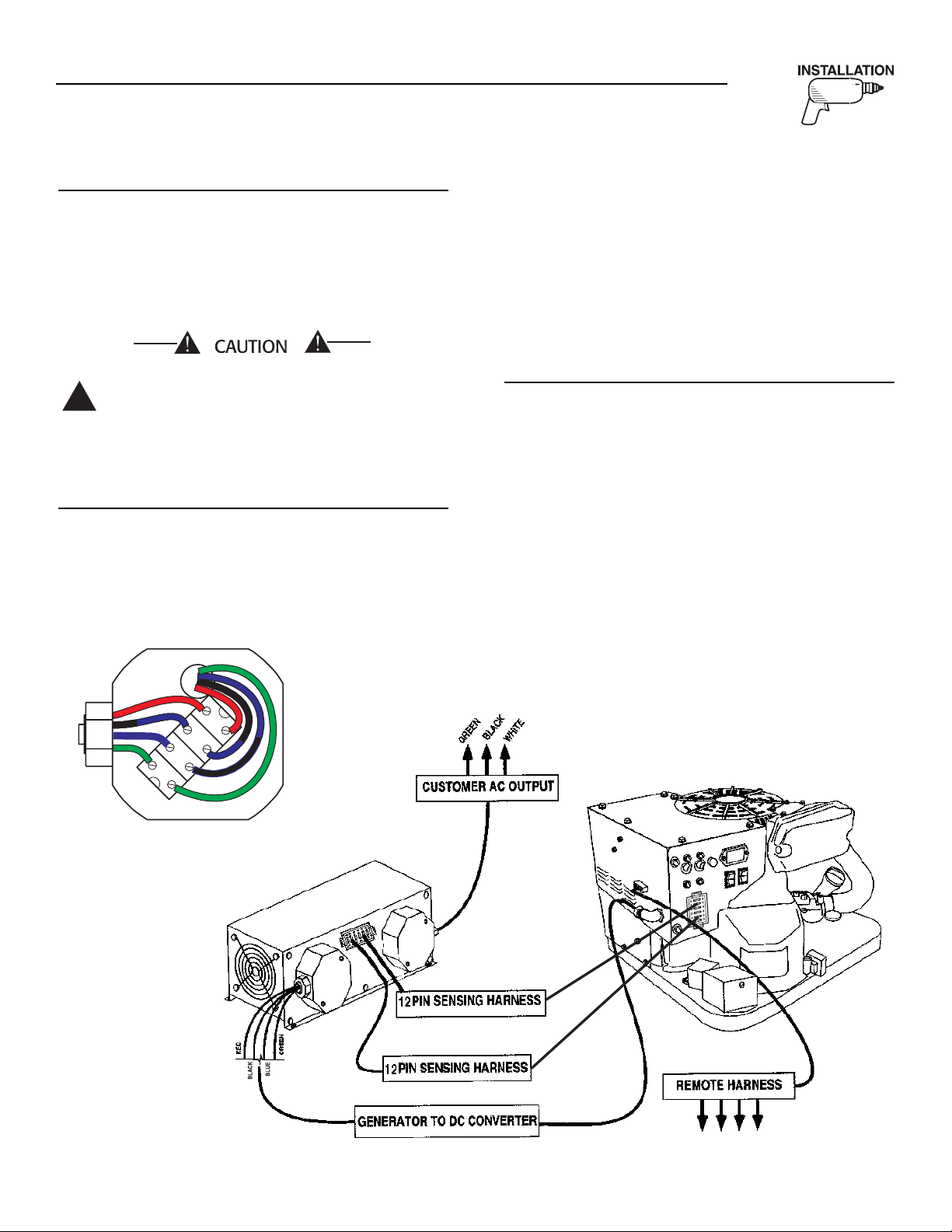
Generac®Power Systems, Inc. 31
Section 2 – Installation
IMPACT-36 plus II Recreational Vehicle Generator
2.6.6 SENSING HARNESS
A sensing harness has been provided with the generator to connect to the inverter (Figure 2.22). It is 12
feet long, however, it is also available in a 24 foot
length: Model # 04612-0. The four (4) DC power
wires (Red, Blue Black, and Green) may be cut to the
desired length to meet the installation (see Figure
2.22).
DO NOT in any way cut or shorten the
sensing harness. If the harness is too long,
simply tie the excess up neatly with standard
cable ties.
2.7 BATTERY INSTALLATION
2.7.1 RECOMMENDED BATTERY
Install a battery that meets the following requirements:
• Battery must be a 12 volt, automotive type storage
battery.
• For prevailing ambient temperatures above 32°F
(0°C), use a battery rated 70 amp-hours and capable of delivering 400 cold cranking amperes.
• For prevailing ambient temperatures below 32°F
(0°C), use a battery rated 95 amp-hours and capable of delivering 450 cold cranking amperes.
IMPORTANT: IF THE BATTERY IS TO BE USED TO
POWER OTHER VEHICLE ACCESSORIES, AS WELL
AS START THE GENERATOR, A BATTERY WITH A
LARGER CAPACITY MAY BE NEEDED.
2.7.2 BATTERY CABLES
Using battery cables that are too long or too small in
diameter may cause a drop in voltage which causes
starting problems. For best cold weather starting, the
voltage drop between battery terminals and the generator connection point should not exceed 0.12 volts
per 100 amperes of cranking current.
Select battery cables based on (a) cable length, and
(b) prevailing ambient temperatures. Generally, the
longer the cable and the colder the weather, the larger the cable size must be as shown in the following
chart.
◆
◆
!
◆
Figure 2.22 — Generator to Inverter Connection
J-BOX - GENERATOR
TO INVERTER INPUT
RED
BLACK
BLUE
GREEN
Page 34

32 Generac®Power Systems, Inc.
* For warm weather, use No. 2 cable up to 20 feet.
2.7.3 BATTERY CABLE CONNECTIONS
1. Connect the battery cable from the battery post or
terminal indicated by a POSITIVE, POS or (+) to
the large lug on the starter contactor as indicated
in Figure 2.23.
2. Connect the battery cable from the battery post
indicated by a NEGATIVE, NEG or (—) to the
frame ground connection.
Figure 2.23 — Connecting Battery Cables
NOTE:
If the generator compartment is grounded to the
vehicle chassis, it’s not necessary to connect a
NEGATIVE battery cable to the frame ground on
the generator base. Connect the negative cable to
the frame ground of the chassis.
3. Connect cables so the connections are clean and
tight.
2.7.4 BATTERY COMPARTMENT
Install the generator battery in its own, vented compartment. Place the battery compartment away from
any source of heat, sparks or flame.
Provide ventilation openings in the battery compartment. The minimum size of openings should be 2
square inches at the top of the compartment. Mount
the battery on a strong, rigid supporting structure,
where leaks and spills of battery fluid will not cause
damage.
2.8 OPTIONAL ACCESSORIES
2.8.1 REMOTE PLUG-IN RECEPTACLE
A plug-in receptacle (Figure 2.24) is provided on the
generator set, near the DC power wires. Use this
receptacle to connect an optional remote-mounted
start/stop panel to the generator. Installation of such
a panel permits starting and stopping the generator
engine from any convenient location inside the vehicle.
Figure 2.24 — Remote Panel Plug-In Receptacle
2.8.2 REMOTE START/STOP PANEL
A remote mounted Start/Stop panel (Figure 2.25) is
available that allows the user to start and stop the
generator engine conveniently from inside the vehicle.
The remote panel includes a Start/Stop switch,
hourmeter, generator run lamp and a wire harness.
Figure 2.25 — Optional Remote Panel
(Models 004057 and 004184)
The remote panels mount a rocker type start/stop
switch, a “Generator Run” advisory lamp and an
hourmeter. The hourmeter should be used in conjunction with the maintenance operations found in
Part I of this manual.
• Model 004057 includes the remote panel and a 10
foot long, 4 wire harness.
• Model 004184 includes the remote panel and a 30
foot long, 4 wire harness.
◆
◆
◆
◆
Section 2 – Installation
IMPACT-36 plus II Recreational Vehicle Generator
CABLE LENGTH
in Feet (Meters) CABLE SIZE
0 to 10 (0 to 3) 2*
11 to 15 (3.4 to 4.5) 0
16 to 20 (4.9 to 6) 000
(13) To Panel
(16) To Starter
Starter
Contacter
Ground Wire
Positive Customer
Connection
(56) Controlled
12 Volts DC
Frame Ground
Page 35

Generac®Power Systems, Inc. 33
3.1 POST INSTALLATION TESTS
The air cooled Impact-36 plus II generator set was
factory tested and adjusted using gasoline as fuel.The
air cooled Impact-34 plus II generator set was factory
tested and adjusted using LP gas as fuel. It is not
required to adjust the unit any further except under
special circumstances.
Do not make any unnecessary adjustments.
Factory settings are correct for most applications. When making adjustments, however, be
careful to avoid overspeeding the engine.
3.2 BEFORE INITIAL START UP
Before starting, complete the following:
1. Check engine crankcase oil level and, if necessary, fill to dipstick FULL mark with the recommended oil. Do not fill above FULL mark.
2. Check the fuel supply. Gas fuel lines must have
been properly purged and leak tested in accordance with applicable fuel codes. All fuel shutoff
valves in the fuel supply lines must be open.
If an LP (propane) gas fuel system has been
installed, it must have been properly tested
for leaks before operating the system in compliance with ANSI A119.2/NFPA 501C. No leakage is permitted. Be sure no gaseous fuel
vapors enter the vehicle interior.
3.3 INITIAL START
When absolutely certain that the unit has been properly installed and prepared for use, start the engine
as follows:
1. Turn off all electrical loads. Do this by setting the
generator main circuit breaker to its “OFF” or
“OPEN” position.
2. Refer to the Owner's Manual shipped with unit for
cranking and starting instructions. The engine
may require more cranking for initial starting
since the fuel lines have to be primed (Use of the
Primer Switch on gasoline units will shorten this
time).
3. Let the engine warm up for about five minutes to
allow internal temperatures to stabilize.
4. Carefully inspect the engine-generator for fuel, oil
and exhaust system leaks. Before proceeding to
the next step, correct any leakage immediately.
5. When all tests and adjustments at no-load are
completed, apply electrical loads and check for
proper operation under load. See “Testing Under
Load”, Section 3.4. Run the unit at least 30 minutes with loads applied.
6. Turn off all electrical loads by setting the generator main circuit breaker to “OFF” or “OPEN.”
7. Let the unit run at no-load for a few minutes to
stabilize internal engine-generator temperatures.
Then, shut down the engine.
IMPORTANT: THE GENERATOR SET WAS THOROUGHLY TESTED AND ADJUSTED AT THE FACTORY BEFORE SHIPPING. NO ADDITIONAL
ADJUSTMENT SHOULD BE NECESSARY. ONLY
QUALIFIED SERVICE TECHNICIANS WHO HAVE
BEEN TRAINED SHOULD PERFORM ADJUSTMENTS OUTLINED IN THIS MANUAL.
3.4 TESTING UNDER LOAD
Apply electrical loads equal to about 75-100% of the
unit's rated wattage/amperage capacity.
Let the unit run at least 30 minutes with load
applied. During this part of the test, check that the
unit is not running excessively hot and that adequate
cooling air flow is available. Do not allow the unit to
overheat during prolonged operation.
NOTE:
The generator engine is equipped with a high temperature switch. The switch has normally-open
(N.O.) contacts. When the temperature is too high,
switch contacts close, and engine shuts down
automatically.
IMPORTANT: GENERAC RECOMMENDS THAT
THE GENERATOR IS TESTED FOR ADEQUATE
COOLING.
Section 3 – Post-installation Start-up Checks
IMPACT-36 plus II Recreational Vehicle Generator
CHECKS
!
DANGER
Page 36

34 Generac®Power Systems, Inc.
Section 3 – Post-installation Start-up Checks
IMPACT-36 plus II Recreational Vehicle Generator
3.5 INSTALLATION CHECKLIST
LOCATION AND SUPPORT
❑ Generator is properly located.
❑ Generator is properly supported.
❑ Generator is properly restrained.
GENERATOR COMPARTMENT
❑ Compartment construction is proper.
❑ Holes/Openings are vapor-sealed.
❑ Compartment size is correct.
❑ Compartment is vapor-sealed.
❑ Sound insulation is correct.
❑ Floor cutouts are properly completed.
COOLING AND VENTILATING AIR
❑ Airflow is adequate.
❑ Air inlet opening is correct.
❑ Compensate for restrictions.
❑ Check that installation has been tested.
DIESEL FUEL SYSTEM
❑ Fuel tank complies with all applicable codes.
❑ Fuel system is properly installed and checked
for leaks.
EXHAUST SYSTEM
❑ Exhaust system complies with all applicable
codes.
❑ Exhaust system is properly and safely installed.
ELECTRICAL CONNECTIONS
❑ Connections comply with local code requirements
and all National Electrical Codes.
❑ Junction box is properly installed.
❑ Wiring meets all standards.
❑ All connections are correct.
❑ Conduit is properly installed and sealed.
❑ Generator is properly bonded to the vehicle.
BATTERY INSTALLATION
❑ Recommended battery is installed.
❑ Recommended cables are installed.
❑ Cables are clean and tight.
❑ Cables are connected properly.
❑ Proper ventilation is provided.
❑ Terminals are coated with anti-corrosion grease,
and terminal covers are positioned.
OPTIONAL ACCESSORIES
❑ Check that remote start/stop panels (if used) are
installed properly.
❑ Check that all other options and accessories (if
used) are installed properly.
POST INSTALLATION TESTS
❑ Check that all tests are completed properly.
◆
◆
◆
◆
◆
◆
◆
◆
◆
DATE OF INSTALLATION ____________________________________________________
NAME OF INSTALLER ______________________________________________________
SIGNATURE OF INSTALLER ________________________________________________
Page 37

Generac®Power Systems, Inc. 35
Section 4 – Troubleshooting
IMPACT-36 plus II Recreational Vehicle Generator
4.1 TROUBLESHOOTING GUIDE
PROBLEM CAUSE CORRECTION
Engine won't crank. 1. Fuse is blown. 1. Replace 15 amp fuse.
2. Loose corroded or defective 2. Tighten, clean or replace
battery cables. as necessary.
3. Defective engine Start/Stop switch. 3. Replace Start/Stop switch.
4. Defective starter contactor. 4. Replace contactor.
5. Defective starter motor. 5. Replace starter motor.
6. Low or defective Battery 6. Charge or replace battery.
Engine cranks but won't start, 1. Out of fuel. 1. Replenish fuel.
low full load power. 2. Fuel pump is defective (Gasoline), OR, 2. Replace defective fuel pump
fuel solenoid is defective (LP). or fuel solenoid.
3. Open Wire #14 from Eng. Control Bd. 3. Reconnect wire.
4. Engine is flooded. 4. Wait 5-10 min. before trying.
5. Spark plug defective. 5. Clean, regap or replace plug.
6. Loose spark plug boot. 6. Press boot on securely.
Engine starts hard, runs rough. 1. Air cleaner plugged or damaged. 1. Clean or replace as needed.
2. Defective spark plug. 2. Clean, regap or replace plug.
Engine starts, shuts down 1. Engine oil is low. 1. Check oil; add as needed.
when Start/Stop switch is 2. Engine is overheated. 2. Check adequate ventilation.
released. 3. Defective Low Oil Pressure System 3. Have serviced/replaced.
4. Defective Control Board 4. Have board serviced/replaced.
5. Defective Computer Control Board. 5. Have board serviced/replaced.
Start/Stop switch at Stop, 1. Defective Start/Stop switch 1. Replace switch.
engine continues to run. 2. Open/disconnected wire #18 between 2. Reconnect or close wire.
Start/Stop switch and Control
3. Open/disconnected wire #0 between 3. Reconnect or close wire.
Start/Stop switch & Control Bd.
4. Defective Control Board 4. Replace board.
No output from generator. 1. Check circuit breaker. 1. Reset to ON or CLOSED.
2. Check vehicle circuit breaker & fuses. 2. Reset and replace if necessary.
3. Transfer sw. set to NORMAL position. 3. Set to GENERATOR position.
4. Generator internal failure. 4. Take generator to an
Authorized Generac facility.
5. Inverter defective. 5. Take generator to an
Authorized Generac facility.
Page 38

36 Generac®Power Systems, Inc.
Section 5 — Electrical Data
IMPACT-36 plus II Recreational Vehicle Generator
Wiring Diagram and Schematic – Drawing No. 0D4947-B
Page 39
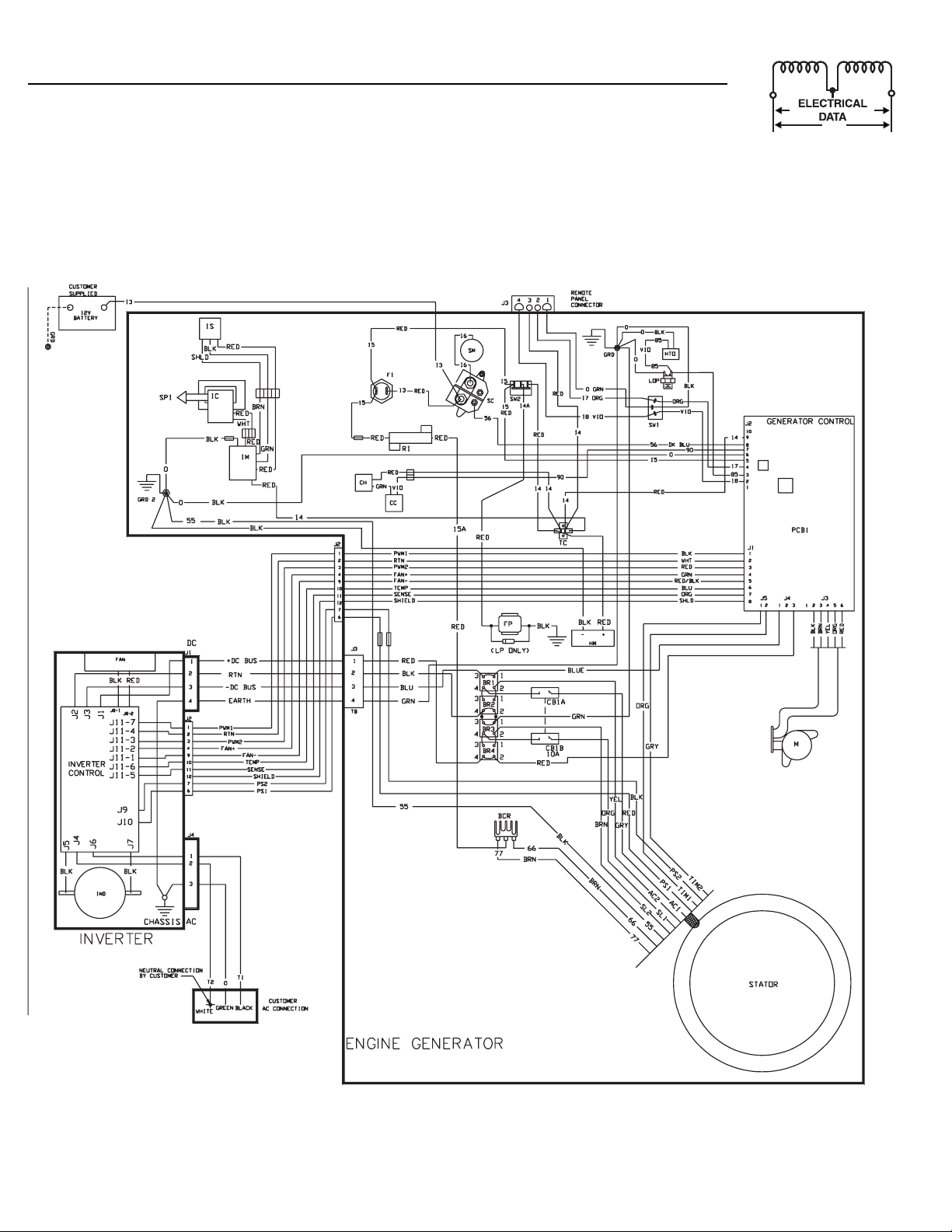
Generac®Power Systems, Inc. 37
Section 5 — Electrical Data
IMPACT-36 plus II Recreational Vehicle Generator
Wiring Diagram and Schematic – Drawing No. 0D4947-B
Page 40

38 Generac®Power Systems, Inc.
9
3
Section 6 — Exploded Views and Parts Lists
IMPACT-36 plus II Recreational Vehicle Generator
Control Panel – Drawing No. 0E7560
1
7
4
1
Page 41

Generac®Power Systems, Inc. 39
ITEM PART NO. QTY. DESCRIPTION
1 091526 7 M5-0.8 X 12MM PHILLIPS PAN HD. MACH. SCR.
2 020093 1 BOX, CONTROL TOP
3 0E7556 1 BOX, CONTROL PANEL
4 075477 1 SCREW PPHM M5-0.8 X 20
5 051716 1 M5-0.8 HEX NUT
6 074908 8 TAPTITE M5- .8 X 10MM
7 023484M 1 SNAP BUSHING
8 0A8592 1 CIRCUIT BREAKER,15A.
9 049226 6 LOCK WASHER-M5
10 075476 10 M4-0.7 X 16MM
11 051715 2 M4-0.7 HEX NUT
12 022985 4 M4 FLAT WASHER
13 023897 7 M5 FLAT WASHER
14 0E7557 1 CONTROL PANEL, FRONT
15 030809 1 RUBBER GROMMET
16 087798 1 SWITCH, SPDT ROCKER
17 092113 1 SWITCH, SPDTMOM ROCKER
18 0A9611 1 FUSE, 7.5A. AGC
19 032300 1 FUSE HOLDER
20 0A6422 1 EXTRUSION, CONTROLLER
21 065795 1 RECTIFIER, BATTERY CHARGE
22 022264 14 LOCK WASHER-M4
23 0E7555 1 PANEL DECAL
24 096874 4 DIODE, DUAL 30A
25 0A6060 1 ASSEMBLY, PCB CCG
26 043181 4 PHMS M3-.05 X 10MM
27 043182 4 LOCK WASHER-M3
28 089744 1 RESISTOR, POWER 1 OHM
29 0A6423A 2 BUS BAR, OUTER
30 045756 4 TAPTITE M6- 1.0 X 10MM
31 086722 1 BRACKET, HEAT SINK-PCB
32 075210A 1 TERMINAL BLOCK
33 0A6423B 4 BUS BAR, INNER
34 0912970025 1 GROUND WIRE
35 0A6470 1 DC POWER HARNESS
36 091269A 1 REMOTE PANEL HARNESS
37 023484D 1 SNAP BUSHING
38 082121A 1 CLAMP, CONTROL PANEL HARNESS
39 051713 2 WASHER FLAT M5
40 025105 4 #6-32 X 1/4" PHILLIPS ROUND HD. MACH. SCREW
41 084867 3.5 RUBBER U-CHANNEL
42 051718 4 M4-0.7 X 10MM HEX HEAD CAPSCREW
43 0C1457 1 HOUR METER
44 036933 4 PPHMS 10-32 X 3/8" LG
45 0A6423C 1 BUS BAR, CENTER
46 029333A 1 BLACK TIE WRAP, 7" LG
47 023762 4 SHAKEPROOF EXT. #10
48 0D4885 1 INVERTER ASSEMBLY
49 051714 2 M3-0.5 NUT
50 0A6464 1 WIRE HARNESS-HEATSINK TO PCBI
51 0D4884 1 WIRE HARNESS
52 0D4882 1 HARNESS-PCBI TO PANEL (NOT SHOWN FOR CLARITY)
53 0A6700 1 HARNESS-HEATSINK TO TERM. BLOCK (NOT SHOWN FOR CLARITY)
54 0A9183 1 HARNESS, CONTROL PANEL (NOT SHOWN FOR CLARITY)
Section 6 — Exploded Views and Parts Lists
IMPACT-36 plus II Recreational Vehicle Generator
Control Panel – Drawing No. 0E7560
Page 42

33
35
31
5
8
32
9
2
8
7
6
6
0
5
60
55
9
028
8
3
53
52
9
56
9
50
8
9
54
51
62
61
9
6
9
9
5
4618
9
3
9
3
5
2
6
5
3
3
58
5
5
6
8
5
63
Section 6 — Exploded Views and Parts Lists
IMPACT-36 plus II Recreational Vehicle Generator
Sheet Metal – Drawing No. 0F1091
40 Generac®Power Systems, Inc.
1
1
1
1
1
2
2
2
2
2
1
1
4
1
4
4
4
4
Page 43

ITEM PART NO. QTY. DESCRIPTION
1 086705 1 PLATE, DIVIDER
2 049813 4 NUT HEX M6 X 1.0
3 022097 9 WASHER LOCK M6-1/4
4 0A1658 3 WASHER LOCK SPECIAL 1/4"
5 086718 3.5' SEAL, RUBBER EXTRUSION
6 0A3666 1 WRAPPER, BOX
7 056893 32 SCREW CRIMPTITE #10-24 X 1/2"
8 0A3638 1 PANEL, WRAPPER BOX
9 074908 31 SCREW HHTT M5-0.8 X 10mm
10 090141A 1 STRAP, EATON GROUND
11 0A8475 2 SPECIAL LOCK WASHER #10
12 0C3296 1 FRAME ASSEMBLY
13 086727 1 SKIRT, SPARK PLUG SIDE
14 086671 1 COVER, ROCKER COVER
15 086726 1 SKIRT, CARB. BAFFLE
16 023897 7 WASHER FLAT #10
17 038353 3 VIBRATION MOUNT
18 022127 5 NUT HEX 1/4"-20
19 0912970071 1 STARTER CONTACTOR GROUND WIRE
20 0742600103 1 GROUND STRAP, UNIT
21 090537 1 RETAINER, SEAL OIL
22 089048 1 SEAL, OIL FILTER HOLE
23 086719 1 PAN, BELLY
24 0A3667 2 MOUNTING BRACKET
25 0A7213 1 TAG, BOLT REMOVAL
26 079119 1 SCREW HHTT 1/4"-20 X 1-1/4"
27 045771 8 NUT HEX M8-1.25
28 022129 12 WASHER LOCK M8-5/16
29 022145 4 WASHER FLAT 5/16-M8
30 066443B 4 VIBRATION MOUNT
31 0A3764 2 CUSTOMER MOUNTING BRACKET
32 039414 4 SCREW HHC M8-1.25 X 35mm
33 020668 2 EARTHING STRAP
ITEM PART NO. QTY. DESCRIPTION
34 092000 1 BRACKET, MUFFLER HANGER
35 079246 2 SCREW HHC M6-1.0 X 16mm W/ LOCK
WASHER
36 086731A 1 ASSEMBLY, MUFFLER
37 094670 1 CLAMP EXHAUST
38 089680 1 SCREEN, SPARK ARREST
39 086715 1 HOUSING, LOWER FAN
40 056892 1 SCREW CRIMPTITE #10-24 X 3/8"
41 089471 1 DEFLECTOR, AIR OUT
42 086724 1 PLATE, BASE COVER
43 086729 1 CONTACTOR, STARTER
44 090518 1 BOOT, CONTACTOR
45 022471 2 NUT HEX #8-32
46 022264 2 WASHER LOCK #8-M4
47 089045 1 SEAL, WASHER EXHAUST PIPE
48 086711 1 MODULE, IGNITION
49 049226 5 WASHER LOCK M5
50 051716 2 NUT HEX M5-0.8
51 0A9196 1 COVER, IGNITION BRACKET
52 089049B 1 ASSEMBLY, IGNITION COIL
53 049721 2 SCREW HHC M6-1.0 X 35mm
54 089047 2 SPACER, IGNITION COIL
55 0A9172 1 BRACKET, IGNITION SYSTEM
56 091526 2 SCREW PPHM M5-0.8 X 12mm
57 084867 .5 RUBBER "U" CHANNEL
58 0A9031 1 WIRE ASSEMBLY, BLOCKING DIODE
59 050830 3 SCREW HHC M5-0.8 X 40mm
60 - 1 REGULATOR ASSEMBLY (SEE E.V.
OF1092)
61 047290 1 HOSE-3/8" I.D. x 11" LONG
62 0C7649 1 CLAMP HOSE 0.38"-0.87"
63 023484D 1 SNAP BUSHING
64 0E8245 1 BRACKET, REGULATOR MOUNT
Section 6 — Exploded Views and Parts Lists
IMPACT-36 plus II Recreational Vehicle Generator
Sheet Metal – Drawing No. 0F1091
Generac®Power Systems, Inc. 41
Page 44
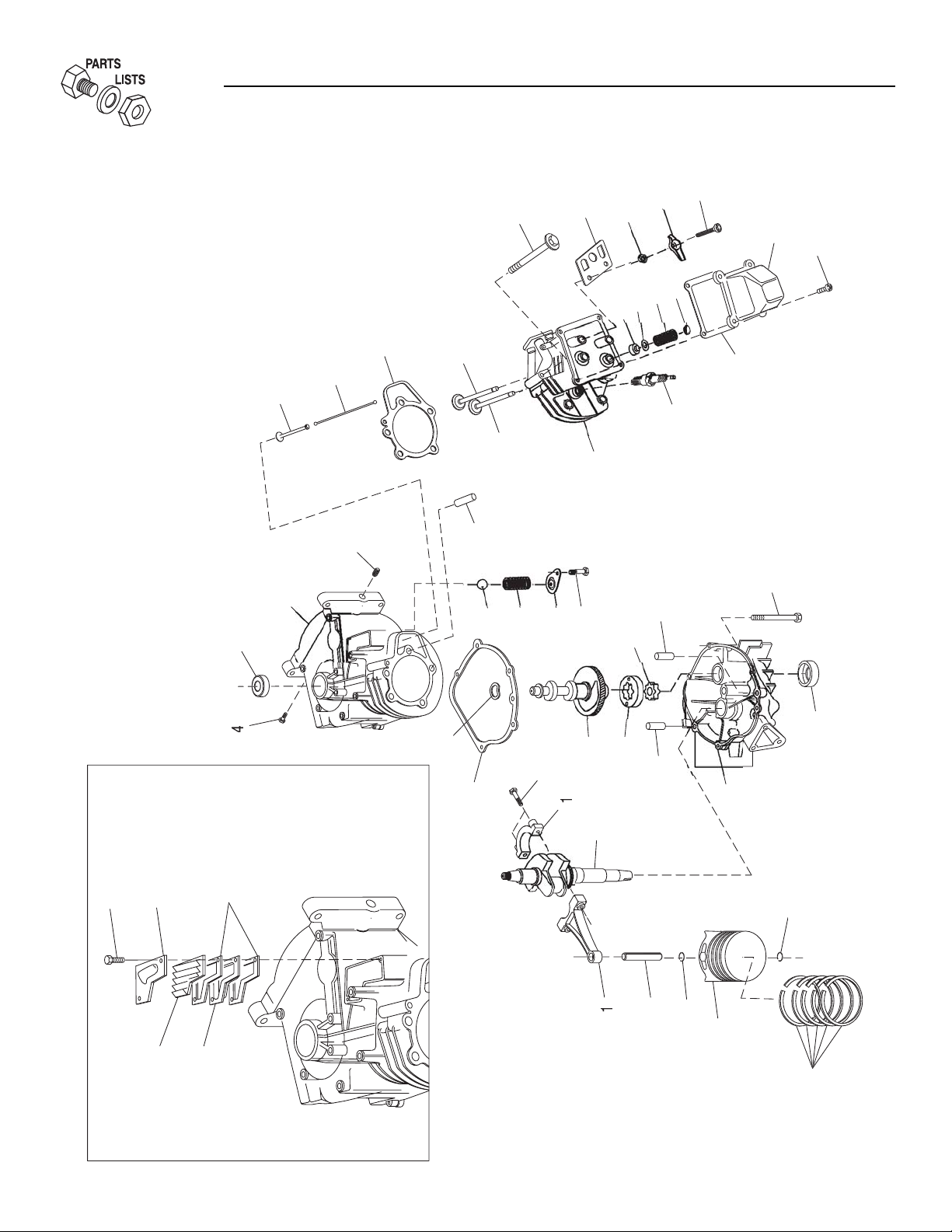
42 Generac®Power Systems, Inc.
Section 6 — Exploded Views and Parts Lists
IMPACT-36 plus II Recreational Vehicle Generator
GN 220 RV Long Block – Drawing No. 0A6202-H
7
1
4
2
1
4
2
Page 45

Generac®Power Systems, Inc. 43
ITEM PART NO. QTY. DESCRIPTION
1 078621 1 ASSY, CONNECTING ROD
2 076389 1 PISTON PIN
3 088411 1 PISTON RING SET
4 072657A 2 PLUG, 1/4 NPTF PIPE
5 077176 1 COVER, BREATHER
6 088057 1 PISTON, DIA 75
7 076390 2 RING, PIN RETAINER
8 083379A 1 ASSY, C'SHFT CCG TPR
10 089923 1 SPRTR, OIL BREATHER
11 089213G 1 CRNKCASE,SUBASY W/PLUG GN220RV
13 0E3811 2 SEAL, D 28 X 41.47 VITON OIL
14 090604 1 ASSY, BREATHER CUP
17 078699B 3 SLEEVE SEAMED DOWEL 12 DIA.
18 0A9878 1 CAMSHAFT ASSY
19 089096 1 GASKET,C'CASE
21 0A8822 1 GASKET, CYL. HEAD
22 078691 1 COVER OIL PRES RELIEF
23 0A5772 1 SPRING,OIL RELIF 220
24 0A5776 1 BALL,DIA 11/32 PRELF
25 074908 1 SCREW HHTT M5-0.8 X 10 BP
26 078606 4 SCREW & LW M6-1 X 12
28 0D2414 6 SCREW HHFC M8-1.25 X 35
30 0C3733 2 RETAINER, VALVE
31 0C4390 2 SPRING, VALVE
32 088590 1 DOWEL DIA 12 X 18L
33 083152 1 GEROTER, INNER 6/5
34 076381 2 BOLT, CON ROD
36 021705B 1 ASSY,CYL HD GDS&STS
37 0C3590 1 VALVE, EXHAUST
38 0C3591 1 VALVE, INTAKE
39 0D9853A 2 PUSHROD 145.76
40 083235 2 TAPPET, DIA 7.5
42 0C8754 1 GASKET, VALVE COVER
43 077161 2 STUD, PIVOT BALL
44 077160 2 ARM, ROCKER, GN191
45 076307 2 NUT, JAM (ROCKR ARM)
46 088403 1 PLATE,PUSHROD GUIDE
47 077168 5 HEADBOLT M8 X 56 MM
48 088413B 1 COVER ROCKER W/OUT BREATHER
49 078629 2 GASKET, BREATHER
50 090388 2 SCREW HHTT M6-1.0 X 12 YC
51 083153 1 GEROTER, OUTER 6/5
52 092977 1 ASSY,OIL SUMP 220RV
53 084186 2 WEAR WSHER,VLV SPRNG
54 088156 1 SEAL,VALVE STEM 6.0
58 072347 1 SPARK PLUG (00940 ONLY)
0E7585 1 SPARK PLUG (00941 ONLY)
59 099922 1 WASHER,SPRING
Section 6 — Exploded Views and Parts Lists
IMPACT-36 plus II Recreational Vehicle Generator
GN 220 RV Long Block – Drawing No. 0A6202-H
Page 46

9
66
81
8
3
0
3
5
5
6
9
9
3
5
3
8
9
6
3
Section 6 — Exploded Views and Parts Lists
IMPACT-36 plus II Recreational Vehicle Generator
Generator – Drawing No. 0F1134
44 Generac®Power Systems, Inc.
7
7
7
2
4
4
7
4
4
4
4
2
2
2
2
1
1
1
1
Page 47

ITEM PART NO. QTY. DESCRIPTION
1 0A2467 1 ENGINE, LONG BLOCK
2 094583 1 FLYWHEEL, FAN
3 083312 2 WASHER, CONICAL
4 081810 2 NUT HEX M16-1.5
5 070185B 1 FILTER, OIL
6 086730 1 TUBE, EXHAUST OUTLET
7 089476 1 GASKET, EXHAUST
8 040976 2 SCREW SHC M8-1.25 X 20mm
9 0D2446 1 ADAPTOR, OIL FILTER
10 087478 1 GASKET, OIL FILTER ADAPTOR
11 086714 1 SCREEN, OIL PICK-UP
12 0A8584 1 10 PSI OIL PRESSURE SWITCH
13 0912970071 1 GROUND WIRE (PRESSURE SWITCH)
14 0912970003 1 TEMP. SWITCH WIRE
15 0912970005 1 OIL PRESSURE SWITCH WIRE
16 097962 4 SCREW SHC M6-1.0 X 25mm
17 022097 8 WASHER LOCK M6-1/4"
18 0C2908 1 GASKET, OIL DRAIN PLUG
19 052617 1 SCREW HHC M12-1.75 X 20mm
20 094090 1 SWITCH, THERMAL OIL TEMP.
21 043182 2 WASHER LOCK M3
22 0C1085 2 SCREW PPHM M3-0.5 X 8mm
23 090051 2 GASKET, CARBURETOR / SPACER /
HEAD
24 086708 1 CARBURETOR SPACER
25 086726 1 SKIRT, BAFFLE
26 078631 1 GASKET, CARBURETOR / SKIRT
27 0A2774B 1 CARBURETOR ASSEMBLY
28 096459 1 GASKET, CARBURETOR/INLET
ADAPTOR
29 086709 1 ADAPTOR, CARBURETOR INLET
30 089050 2 PPHMS, #M6-1 X 90mm LONG
31 035586 2 HOSE CLAMP-BAND #20
32 0F1225 1 HOSE, CARBURETOR INLET
33 090072 1 O-RING .562" I.D.
34 094637 1 OIL FILL TUBE
35 090071 1 O-RING, 1.062" I.D.
36 089263 1 ASSEMBLY, OIL FILL CAP & DIPSTICK
37 049226 4 WASHER LOCK M5
38 056893 1 SCREW CRIMPTITE #10-24 X 1/2"
39 038353 3 RUBBER MOUNTS
40 059637 4 SCREW HHTT 3/8"-16 X 3/4"
41 086701 1 BRACKET, ENGINE MOUNT FRONT
42 086702 1 BRACKET, ENGINE MOUNT REAR
43 086704 3 SPACER, ENGINE MOUNT
44 022237 3 WASHER LOCK 3/8"
45 022511 3 SCREW HHC 3/8"-16 X 1-1/4"
ITEM PART NO. QTY. DESCRIPTION
46 086705 1 PLATE, DIVIDER
47 090192 1 WASHER, CARBURETOR
48 089477 1 CLIP, ADJUSTMENT
49 086706 1 ROD, THROTTLE CONTROL
50 089478 1 SNAP, RETAINING
51 078609 2 BOLT, AIR CLEANER COVER
52 086674 1 COVER, AIR BOX
53 078601 1 ELEMENT, AIR FILTER
54 059635 1 PLASTITE SC #8 X 0.37"
55 090613 1 COVER, BREATHER CANAL
56 089062A 1 HOSE, BREATHER
57 086673 1 BASE, AIR BOX
58 090021 1 BRACKET, AIR CLEANER SUPPORT
59 049815 8 SCREW HHC M5-0.8 X 16mm
60 023897 6 WASHER FLAT #10
61 087993 1 ELBOW, AIR CLEANER OUTLET
62 090536 1 GASKET, AIR CLEANER OUTLET
63 094665 1 HOUSING, FAN-UPPER
64 045756 3 SCREW HHTT M6-1.0 X 10mm
65 042907 3 SCREW HHC M8-1.25 X 16mm
66 022129 10 WASHER LOCK M8-5/16"
67 093859 1 FAN, GENERATOR
68 074908 3 SCREW HHTT M5-0.8 X 10mm
69 055822 2 SCREW PHM M4-0.7 X 8mm
70 022264 2 WASHER LOCK #8-M4
71 086697 1 ASSEMBLY IGNITION SENSOR
72 086692 1 ADAPTOR. STATOR
73 0A5892 1 ASSEMBLY, MAGNET HOUSING
74 080934 1 RETAINING RING, STATOR
75 066449C 4 BOLT, M6-1.0 X 80mm LONG
76 0D4883 1 ASSEMBLY STATOR
77 074906 4 SCREW HHTT M6-1.0 X 20mm
78 0912970004 1 TEMP SWITCH GROUND WIRE
79 0A8475 2 LOCK WASH SPECIAL #10
80 096627 1 BRACKET, STARTER SIDE ENGINE
MNT.
81 039253 3 SCREW HHC M8-1.25 X 20mm
82 082774 1 WOODRUFF KEY-4 x 19MM
83 092800 1 WRAPPER, ENGINE TOP
84 088905 1 EXTENSION SPRING
85 083512 1 SCREW HHTT M8-1.2 X 16mm
86 059636 1 SCREW PPPH #4 X 0.37"
87 0D4408 1 STARTER MOTOR
88 022145 2 WASHER FLAT 5/16"-M8
89 0912970002 1 STARTER WIRE
90 092059 1 STEPPER MOTOR SPEED CONTROL
91 049821 2 SCREW SHC M8-1.25 X 30mm
Section 6 — Exploded Views and Parts Lists
IMPACT-36 plus II Recreational Vehicle Generator
Generator – Drawing No. 0F1134
Generac®Power Systems, Inc. 45
Page 48

ITEM PART NO. QTY. DESCRIPTION
1 0D5694 1 CASTING, TWIN REGULATOR
HOUSING
2 075475 4 SCREW PPHM M4-0.7 X 10
3 022264 4 WASHER LOCK #8-M4
4 043180 4 WASHER FLAT M4
5 0F3154 1 SOLENOID COIL, 12VDC
6 0C6070 1 SPRING-SOLENOID PLUNGER
7 0C4680 1 PLUNGER LP REG. ASSY
8 0C4647 1 GASKET, SOLENOID
9 0C4643 1 INLET, TWIN REGULATOR NO HOLE
10 0D3973 1 PLUG, EXPANSION 16MM TWINREG
11 0D7023 1 BARBED ELBOW 90 1/2"NPT X 3/8"
HOSE
12 072683A 2 PLUG 1/8" NPTF PIPE
13 0D3308 2 WASHER FLAT 3.2MM ID X 10MM OD
14 070728 2 SCREW PFILHM M3-0.5 X 5
ITEM PART NO. QTY. DESCRIPTION
15 0C5764A 1 SPRING, REGULATOR 45N/M 29MM
16 0C4643A 1 INLET, TWIN REG 11.11 DIA.
17 0C6066 1 SEAL, INLET REGULATOR
18 0C5968 1 SUPPORT, INLET SEAL
19 0C5759 1 PIN, PIVOT ARM
20 0C5761 1 LEVER, REGULATOR
21 0C6069 1 GASKET, DIAPHRAGM
22 0C6731 1 RIVET .118 X .125 ALUMINUM
23 0C6067 1 SUPPORT, DIAPHRAGM
24 0C4706 1 DIAPHRAGM, TWIN REGULATOR
25 0C6068 1 CAP, DIAPHRAGM SUPPORT
26 0C5762 1 COVER,TWIN REGULATOR
27 045764 8 SCREW HHTT M4-0.7 X 8 BP
28 025425 1 ELBOW 45D STREET 3/4" NPT
29 0E4170 1 CONNECTION 3/4"NPT - 3/8" 45D
30 0C5760 1 JET LP GN220 ENGINE
3
0
5
8
6
5
0
8
9
3
9
6
Section 6 — Exploded Views and Parts Lists
IMPACT-36 plus II Recreational Vehicle Generator
LP Regulator – Drawing No. 0F1092-A
46 Generac®Power Systems, Inc.
1
2
2
1
1
1
1
1
2
2
2
2
Page 49

Section 7 — Installation Diagram
IMPACT-36 plus II Recreational Vehicle Generator
Major Features and Dimensions – Drawing No. 0F1119
Generac®Power Systems, Inc. 47
Page 50

48 Generac®Power Systems, Inc.
Section 8 – Warranty
IMPACT-36 plus II Recreational Vehicle Generator
CALIFORNIA AND FEDERAL EMISSION CONTROL WARRANTY STATEMENT
YOUR WARRANTY RIGHTS AND OBLIGATIONS
The California Air Resources Board (CARB) and the United States Environmental Protection Agency (EPA), together with
Generac Power Systems, Inc. (Generac), are pleased to explain the Emission Control System Warranty on your new engine.*
New utility, and lawn and garden equipment engines must be designed, built and equipped to meet stringent anti-smog standards for the state of California and the federal government. Generac will warrant the emission control system on your engine
for the periods of time listed below provided there has been no abuse, neglect, unapproved modification or improper maintenance of your engine.
Your emission control system may include parts such as the carburetor, ignition and exhaust systems. Generac will repair your
engine at no cost to you for diagnosis, replacement parts and labor, should a warrantable condition occur.
MANUFACTURER’S EMISSION CONTROL SYSTEM WARRANTY COVERAGE:
Emissions control systems on 1997 and later model year engines are warranted for two years as hereinafter noted. If, during
such warranty period, any emission-related component or system on your engine is found to be defective in materials or workmanship, repairs or replacement will be performed by a Generac Authorized Warranty Service Facility.
PURCHASER’S/OWNER’S WARRANTY RESPONSIBILITIES:
As the engine purchaser/owner, you are responsible for the completion of all required maintenance as listed in your factory
supplied Owner’s Manual. For warranty purposes, Generac recommends that you retain all receipts covering maintenance on
your engine. However, Generac cannot deny warranty solely because of the lack of receipts or for your failure to ensure the
completion of all scheduled maintenance.
As the engine purchaser/owner, you should, however, be aware that Generac may deny any and/or all warranty coverage or
responsibility if your engine, or a part/component thereof, has failed due to abuse, neglect, improper maintenance or unapproved modifications, or the use of counterfeit and/or “grey market” parts not made, supplied or approved by Generac.
You are responsible for presenting your engine to a Generac Authorized Warranty Service Facility as soon as a
problem occurs. The warranty repairs should be completed in a reasonable amount of time, not to exceed 30 days.
Warranty service can be arranged by contacting either your selling dealer or a Generac Authorized Warranty Service Facility .
To locate the Generac Authorized Warranty Service Facility nearest you, call our toll-free number:
1-800-333-1322
IMPORTANT NOTE: This warranty statement explains your rights and obligations under the Emission Control System Warranty
(ECS Warranty), which is provided to you by Generac pursuant to California and federal law. See also the “Generac Limited
Warranties for Generac Power Systems, Inc.,” which is enclosed herewith on a separate sheet, also provided to you by Generac.
The ECS Warranty applies only to the emission control system of your new engine. If there is any conflict in terms between
the ECS Warranty and the Generac Warranty, the ECS Warranty shall apply except in circumstances where the Generac
Warranty may provide a longer warranty period. Both the ECS Warranty and the Generac Warranty describe important rights
and obligations with respect to your new engine.
Warranty service can be performed only by a Generac Authorized Warranty Service Facility. When requesting warranty service, evidence must be presented showing the date of the sale to the original purchaser/owner. The purchaser/owner shall be
responsible for any expenses or other charges incurred for service calls and/or transportation of the product to/from the
inspection or repair facilities. The purchaser/owner also shall be responsible for any and/or all damages or losses incurred while
the engine is being transported/shipped for inspection or warranty repairs.
If you have any questions regarding your warranty rights and responsibilities, you should contact Generac at the
following address:
ATTENTION WARRANTY DEPARTMENT
GENERAC POWER SYSTEMS, INC.
P.O . B OX 8
WAUKESHA, WI 53187
Part 1
Page 51

Generac®Power Systems, Inc. 49
Section 8 – Warranty
IMPACT-36 plus II Recreational Vehicle Generator
EMISSION CONTROL SYSTEM WARRANTY
Emission Control System Warranty (ECS Warranty) for 1997 and later model year engines:
(a) Applicability: This warranty shall apply to 1997 and later model year engines. The ECS Warranty Period shall begin on the
date the new engine or equipment is purchased by/delivered to its original, end-use purchaser/owner and shall continue for
24 consecutive months thereafter.
(b) General Emissions Warranty Coverage: Generac warrants to the original, end-use purchaser/owner of the new engine or
equipment, and to each subsequent purchaser/owner, that each of its engines is ...
(1) Designed, built and equipped so as to conform with all applicable regulations adopted by the EPA and CARB pursuant to
their respective authority, and
(2) Free from defects in materials and workmanship which, at any time during the ECS Warranty Period, may cause a war-
ranted emissions-related part to fail to be identical in all material respects to the part as described in the engine manufacturer’s application for certification.
(c) The ECS Warranty only pertains to emissions-related parts on your engine, as follows:
(1) Any warranted, emissions-related parts that are not scheduled for replacement as required maintenance in the Owner’s
Manual shall be warranted for the ECS Warranty Period. If any such part fails during the ECS Warranty Period, it shall be
repaired or replaced by Generac according to Subsection (4) below. Any such part repaired or replaced under the ECS
Warranty shall be warranted for the remainder of the ECS Warranty Period.
(2) Any warranted, emissions-related part that is scheduled only for regular inspection as specified in the Owner’s Manual
shall be warranted for the ECS Warranty Period. A statement in such written instructions to the effect of “repair or replace
as necessary” shall not reduce the ECS Warranty Period. Any such part repaired or replaced under the ECS Warranty shall
be warranted for the remainder of the ECS Warranty Period.
(3) Any warranted, emissions-related part that is scheduled for replacement as required maintenance in the Owner’s Manual
shall be warranted for the period of time prior to the first scheduled replacement point for that part. If the part fails prior
to the first scheduled replacement, the part shall be repaired or replaced by Generac according to Subsection (4) below.
Any such emissions-related part repaired or replaced under the ECS Warranty shall be warranted for the remainder of the
ECS Warranty Period prior to the first scheduled replacement point for such emissions-related part.
(4) Repair or replacement of any warranted, emissions-related part under this ECS Warranty shall be performed at no charge
to the owner at a Generac Authorized Warranty Service Facility.
(5) When the engine is inspected by a Generac Authorized Warranty Service Facility, the owner shall not be held responsible
for diagnostic costs if the repair is deemed warrantable.
(6) Generac shall be liable for damages to other original engine components or approved modifications proximately caused
by a failure under warranty of any emission-related part covered by the ECS Warranty.
(7) Throughout the ECS Warranty Period, Generac shall maintain a supply of warranted emission-related parts sufficient to
meet the expected demand for such emission-related parts.
(8) Any Generac authorized and approved emission-related replacement part may be used in the performance of any ECS
Warranty maintenance or repairs and will be provided without charge to the purchaser/owner. Such use shall not reduce
Generac’s ECS Warranty obligations.
(9) Unapproved, add-on, modified, counterfeit and/or “grey market” parts may not be used to modify or repair a Generac
engine. Such use voids this ECS Warranty and shall be sufficient grounds for disallowing an ECS Warranty claim. Generac
shall not be held liable hereunder for failures of any warranted parts of a Generac engine caused by the use of such an
unapproved, add-on, modified, counterfeit and/or “grey market” part.
EMISSION RELATED PARTS INCLUDE THE FOLLOWING:
*Generac engine types covered by this warranty statement include the following:
1) Utility
2) Lawn and Garden Equipment
3) Recreational Vehicle (RV) Generator
4) Industrial Mobile (IM) Generator
Part 2
1) Fuel Metering System:
1.1) Gasoline carburetor assembly and its
internal components (if so equipped).
a) Fuel filter (if so equipped)
b) Carburetor gaskets
c) Fuel pump (if so equipped)
1.2) LPG carburetion assembly and its
internal components (if so equipped).
a) Fuel controller (if so equipped)
b) Mixer and its gaskets (if so equipped)
c) Carburetor and its gaskets (if so equipped)
d) Primary gas regulator (if so equipped)
e) LP liquid vaporizer (if so equipped)
2) Air Induction System including:
a) Intake pipe/manifold
b) Air cleaner
3) Ignition System including:
a) Spark plug
b) Ignition module
4) Catalytic Muffler Assembly (if so equipped) including:
a) Muffler gasket
b) Exhaust manifold
5) Crankcase Breather Assembly including:
a) Breather connection tube
Page 52

Part No. 0F1117 Revision B (11/15/04) Printed in U.S.A.
Section 8 – Warranty
IMPACT-36 plus II Recreational Vehicle Generator
GENERAC POWER SYSTEMS’ THREE-YEAR LIMITED WARRANTY
FOR GUARDIAN RECREATIONAL VEHICLE GENERATORS
NOTE: ALL UNITS MUST BE INSTALLED BY GENERAC POWER SYSTEMS AUTHORIZED SERVICE FACILITIES.
For a period of 3 (three) years of operation from the date of original sale, Generac Power Systems, Inc. (Generac) will, at its
option, repair or replace any part which, upon examination, inspection and testing by Generac or a Generac Authorized
Warranty Service Facility, is found to be defective under normal use and service, in accordance with the warranty schedule
set forth below. Any equipment that the purchaser/owner claims to be defective must be returned to and examined by the
nearest Generac Authorized Warranty Service Facility. All transportation costs under the warranty, including return to the
factory, are to be borne and prepaid by the purchaser/owner. This warranty applies only to Generac generators sold and
rated for “Recreational Vehicle” (RV) applications, as Generac has defined Recreational Vehicle generator applications. The
factory recommends exercising the unit one half-hour every season.
WARRANTY SCHEDULE – COMMERCIAL APPLICATIONS
YEAR ONE – 100% (one hundred percent) coverage on part(s), labor, removal and reinstallation listed:
• Engine – All components
• Alternator – All components
WARRANTY SCHEDULE – CONSUMER/PERSONAL APPLICATIONS
YEARS ONE AND TWO
– 100% (one hundred percent) coverage on part(s), labor, removal and reinstallation listed:
• Engine – All components
• Alternator – All components
YEAR
THREE – 100% (one hundred percent) only on selected part(s) and labor listed (Any labor and part(s) not listed, and
removal and reinstallation are the owner’s responsibility):
• Rotor, Stator, Computer Control Board (part numbers 0A6060 and 0A3369) and inverter, (if applicable with regard to the generator) Cylinder Block, Cylinder Head, Crankshaft, Piston(s), Valve, Valve Lifter(s), Intake and Exhaust Manifolds
Generac RV generators manufactured prior to December 31, 1997, DO NOT have a transferable warranty. Generac RV generators manufactured after January 1, 1998, have a transferable warranty to the second owner ONLY for the remainder of
the three-year limited warranty. Proof-of-purchase is required and must be presented to a Generac Authorized Warranty
Service Facility prior to the performance of any warranty service.
All warranty expense allowances are subject to the conditions defined in Guardian’s Warranty Policies and Procedures Guide.
THIS WARRANTY SHALL NOT APPLY TO THE FOLLOWING:
• Generac Guardian generators that utilize non-Generac replacement parts.
• Costs of normal maintenance, adjustments, installation and start-up.
• Failures caused by any contaminated fuels, oils, coolants or lack of proper fluid amounts.
• Failures due, but not limited, to normal wear and tear, accident, misuse, abuse, negligence or improper installation. As with
all mechanical devices, the Generac engines need periodic part(s) service and replacement to perform well. This warranty
will not cover repair when normal use has exhausted the life of a part(s) or engine.
• Failures caused by any external cause or act of God, such as collision, theft, vandalism, riot or wars, nuclear holocaust, fire,
freezing, lightning, earthquake, windstorm, hail, volcanic eruption, water or flood, tornado or hurricane.
• Damage related to rodent and/or insect infestation.
• Products that are modified or altered in a manner not authorized by Generac in writing.
• Any incidental, consequential or indirect damages caused by defects in materials or workmanship, or any delay in repair or
replacement of the defective part(s).
• Failure due to misapplication.
• Telephone, cellular phone, facsimile, internet access or other communication expenses.
• Living or travel expenses of person(s) performing service, except as specifically included within the terms of a specific unit
warranty period.
• Expenses related to "customer instruction" or troubleshooting where no manufacturing defect is found.
• Rental equipment used while warranty repairs are being performed.
• Overnight freight costs for replacement part(s).
• Overtime labor.
• Starting batteries, fuses, light bulbs and engine fluids.
THIS WARRANTY IS IN PLACE OF ALL OTHER WARRANTIES, EXPRESSED OR IMPLIED. SPECIFICALLY, GENERAC MAKES
NO OTHER WARRANTIES AS TO THE MERCHANTABILITY OR FITNESS FOR A PARTICULAR PURPOSE. Some states do not
allow limitations on how long an implied warranty lasts, so the above limitation may not apply to you.
GENERAC'S ONLY LIABILITY SHALL BE THE REPAIR OR REPLACEMENT OF PART(S) AS STATED ABOVE. IN NO EVENT
SHALL GENERAC BE LIABLE FOR ANY INCIDENTAL OR CONSEQUENTIAL DAMAGES, EVEN IF SUCH DAMAGES ARE A
DIRECT RESULT OF GENERAC'S NEGLIGENCE. Some states do not allow the exclusion or limitation of incidental or consequential damages, so the above limitation may not apply to you.
This warranty gives you specific legal rights. You also have other rights from state to state.
GENERAC®POWER SYSTEMS, INC.
P.O. BOX 297 • WHITEWATER, WI 53190
Revision 2.04
 Loading...