

Page 1
Owner'sManual
AutomaticStandbyGenerator
Page 2
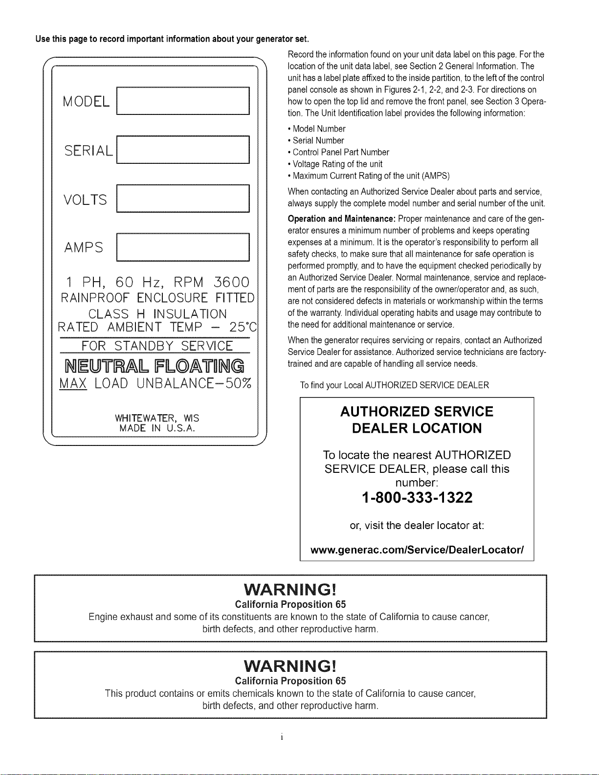
Usethispageto recordimportantinformationaboutyourgeneratorset.
,._ Recordtheinformationfoundonyourunitdatalabelonthispage.Forthe
location of the unit data label, see Section 2 General information. The
unit has a label plateaffixed to the inside partition, to the leftof the control
panel console as shown in Figures 2-1, 2-2, and 2-3. For directions on
MODEL[
SERIAL[
VOLTS[
AMPS i
1 PH, 60 Hz, RPM 5600
RAINPROOF ENCLOSURE FITTED
CLASS H INSULATION
RATED AMBIENT TEMP - 25°C
FOR STANDBY SERVICE
NEUTRAL FL©AWIN@
MAX LOAD UNBALANCE-50%
how to open the top lid and remove the front panel, see Section 3 Opera-
tion. The Unit Identification label provides the following information:
• Model Number
• Serial Number
• Control Panel Part Number
• Voltage Rating of the unit
• Maximum Current Rating of the unit (AMPS)
When contacting an Authorized Service Dealer about parts and service,
always supply the complete model number and serial number of the unit.
Operation and Maintenance: Proper maintenance and care of the gen-
erator ensures a minimum number of problems and keepsoperating
expenses at a minimum. It is the operator's responsibility to perform all
safety checks, to make sure that all maintenance for safe operation is
performed promptly, and to have the equipment checked periodically by
an Authorized Service Dealer. Normal maintenance, service and replace-
ment of parts are the responsibility of the owner/operator and, as such,
are not considered defects in materials orworkmanship within the terms
of the warranty, individual operating habits and usage may contribute to
the need for additional maintenance or service.
When the generator requires servicing or repairs, contact an Authorized
Service Dealer for assistance. Authorized service technicians are factory-
trained and are capable of handling all service needs.
Tofind your Local AUTHORIZED SERVICE DEALER
WHITEWATER, WIS
MADE IN U.S.A.
AUTHORIZED SERVICE
DEALER LOCATION
To locate the nearest AUTHORIZED
SERVICE DEALER, please call this
number:
1-800-333-1322
or, visit the dealer Iocator at:
www.generac.comlServicelDealerLocatorl
WARNING!
California Proposition 65
Engine exhaust and some of its constituents are known to the state of California to cause cancer,
birth defects, and other reproductive harm.
WARNING!
California Proposition 65
This product contains or emits chemicals known to the state of California to cause cancer,
birth defects, and other reproductive harm.
Page 3
Table of Contents
Section 1 --Safety ............................................................................ 1
1.1 -- General Safety ........................................................................ 2
1.2 -- General Safety Hazards ................................................................. 2
1.3 -- Exhaust Hazards ...................................................................... 3
1.4 -- Electrical Hazards ..................................................................... 3
1.5 -- Fire Hazards .......................................................................... 3
1.6 -- Explosion Hazards ..................................................................... 3
Section 2- General Information .................................................................. 5
2.1 -- The Generator ........................................................................ 5
2.2 -- Protection Systems .................................................................... 6
2.3 -- Emission Information ................................................................... 7
2.4 -- Specifications ......................................................................... 8
2.5 -- Accessories .......................................................................... 9
Section 3 -- Operation ......................................................................... 11
3.1 --Control Panel Interface ................................................................. 11
3.2 -- Using the Auto/Off/Manual Buttons ....................................................... 12
3.3 -- Interface Menu Displays ................................................................ 12
3.4 -- Automatic Transfer Operation ........................................................... 14
3.5- Turning the Generator Off When Operating Under Load ....................................... 15
3.6 -- Manual Transfer Operation .............................................................. 15
3.7 -- Side Compartment .................................................................... 16
3.8- Alarm Response Procedures ............................................................ 17
3.9 -- Battery Charger ...................................................................... 17
3.10 -- Setting the Exercise Timer ............................................................. 17
Section 4 -- Maintenance ...................................................................... 19
4.1 -- Performing Scheduled Maintenance ...................................................... 19
4.2 -- Service Schedule ..................................................................... 19
4.3 -- Checking Engine Oil Level .............................................................. 20
4.4 -- Changing the Engine Air Cleaner ......................................................... 22
4.5 -- Spark Plugs ......................................................................... 22
4.6 -- Valve Lash Adjustment ................................................................. 23
4.7 -- Battery Maintenance .................................................................. 24
4.8 -- Attention After Submersion ............................................................. 25
4.9- Corrosion Protection ................................................................... 25
4.10 -- Out of Service Procedure (includes removal and return from service) ............................ 25
Section 5- Troubleshooting .................................................................... 27
Section 6 -- Quick Reference Guide .............................................................. 29
Also included is Spanish, French Canadian and Portuguese.
Page 4

This page intentionally left blank.
iii
Page 5
Section 1
INTRODUCTION: Thank you for purchasing this compact, high performance, air-cooled, engine-driven stationary automatic standby generator
set. Everyeffort was made to make sure that the information and instructions in this manual were both accurate and current at the time the man-
ual was written. However, the manufacturer reserves the right to change, alter or otherwise improve this product or manual at any time without
prior notice.
This generator is designed to automatically supply electrical power to operate critical loads during a utility power failure. This unit is factory
installed in an all-weather metal enclosure and is intended exclusively for outdoor installation. This generator will operate using either vapor
withdrawn liquid propane (LP) or natural gas (NG).
NOTE:Whenproperlysized,thisgeneratorissuitablefor supplyingtypicalresidentialloads suchas Induction Motors(sump pumps,
refrigerators,airconditioners,furnaces,etc.),ElectronicComponents(computer,monitor,TV,etc.),LightingLoadsandMicrowaves.
READ THIS MANUAL THOROUGHLY: The operator is responsible for proper and safe use of this equipment. The manufacturer strongly recom-
mends that the operator read and thoroughly understand the instructions and contents of this owner's manual before attempting to use theequip-
ment. Ifany portion of this publication is not understood, contact the nearest Authorized Service Dealer for starting, operating and servicing
procedures.
SAVE THESE INSTRUCTIONS: The manufacturer suggests that this manual and the rulesfor safe operation be copied and posted near the
unit's installation site. Safety should be stressed to all operators and potential operators of this equipment.
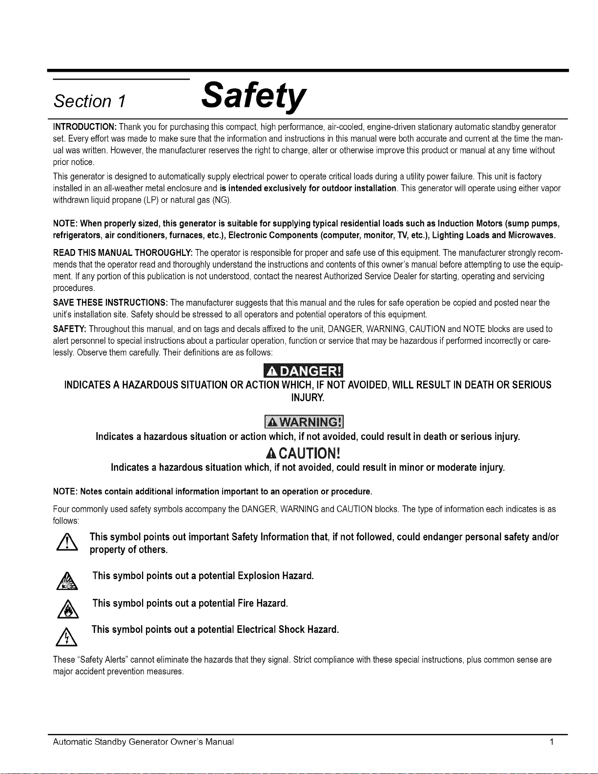
SAFETY: Throughout this manual, and on tagsand decals affixed to the unit, DANGER, WARNING, CAUTION and NOTE blocks are used to
alert personnel to special instructions about a particular operation, function or service that may be hazardous if performed incorrectly or care-
lessly. Observe them carefully. Their definitions are as follows:
INDICATESA HAZARDOUS SITUATIONOR ACTION WHICH, IF NOTAVOIDED, WILL RESULT IN DEATH OR SERIOUS
Safety
INJURY.
Indicates a hazardous situation or action which, ifnot avoided, could result in death or serious injury.
CAUTION!
Indicates a hazardous situation which, if not avoided, could result in minor or moderate injury.
NOTE:Notescontainadditionalinformation important toan operationor procedure.
FourcommonlyusedsafetysymbolsaccompanytheDANGER,WARNINGandCAUTIONblocks.Thetypeof informationeachindicatesis as
follows:
Z_ This symbol points out important Safety Information that, if not followed, could endanger personal safetyand/or
A
/&
property of others.
This symbol points out a potential Explosion Hazard.
This symbol points out a potential Fire Hazard.
This symbol points out a potential Electrical Shock Hazard.
A
These "Safety Alerts" cannot eliminate the hazards that they signal. Strict compliance with these special instructions, plus common sense are
major accident prevention measures.
Automatic Standby Generator Owner's Manual 1
Page 6
1.1 m General Safety
Study these safety rules carefully before operating or servicing this equipment. Becomefamiliar with this Owner's Manual and with the unit. The
generator can operate safely,efficiently and reliably only if it is properly installed, operated and maintained. Many accidents are caused byfailing
to follow simple and fundamental rules or precautions.
The manufacturer cannot anticipate every possible circumstance that might involve a hazard. The warnings in this manual, and on tags and
decals affixed to the unit are, therefore, not all-inclusive, if using a procedure, work method or operating technique the manufacturer does not
specifically recommend, ensure that it is safe for personnel. Also make sure the procedure, work method or operating technique utilized does not
render the generator unsafe.
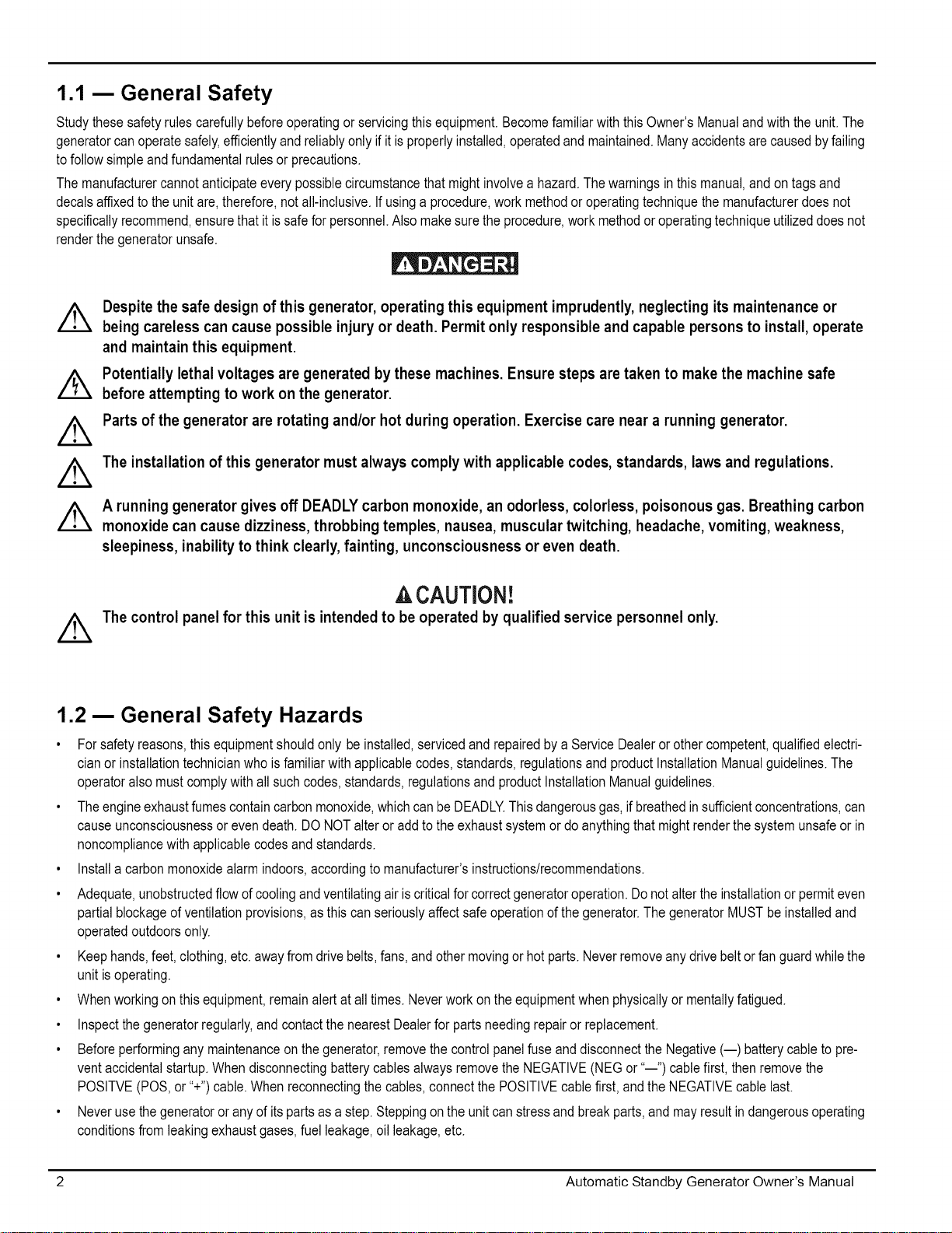
Despite the safe design of this generator, operating this equipment imprudently, neglecting its maintenance or
being careless can cause possible injury or death. Permit only responsible and capable persons to install, operate
and maintain this equipment.
Potentially lethal voltages are generated by these machines. Ensure steps are taken to make the machine safe
beforeattempting to work on the generator.
Parts of the generator are rotating and/or hot during operation. Exercise care near a running generator.
The installation of this generator must always comply with applicable codes, standards, laws and regulations.
A running generator gives off DEADLY carbon monoxide, an odorless, colorless, poisonous gas. Breathing carbon
monoxide can cause dizziness, throbbing temples, nausea, muscular twitching, headache, vomiting, weakness,
sleepiness, inability to think clearly, fainting, unconsciousness or even death.
A CAUTION!
The control panel for this unit is intended to be operated by qualified service personnel only.
1.2 m General Safety Hazards
• For safety reasons, this equipment should only be installed, serviced and repaired by a Service Dealer or other competent, qualified electri-
cian or installation technician who is familiar with applicable codes, standards, regulations and product Installation Manual guidelines. The
operator also must comply with all such codes, standards, regulations and product installation Manual guidelines.
• The engine exhaust fumes contain carbon monoxide, which can be DEADLY.This dangerous gas, if breathed in sufficient concentrations, can
cause unconsciousness or even death. DO NOT alter or add to the exhaust system or do anything that might render the system unsafe or in
noncompliance with applicable codes and standards.
• Install a carbon monoxide alarm indoors, according to manufacturer's instructions/recommendations.
• Adequate, unobstructed flow of cooling and ventilating air is critical for correct generator operation. Do not alter the installation or permit even
partial blockage of ventilation provisions, as this can seriously affect safe operation of the generator. The generator MUST be installed and
operated outdoors only.
• Keep hands, feet, clothing, etc. away from drive belts, fans, and other moving or hot parts. Neverremove any drive belt or fan guard while the
unit is operating.
• When working on this equipment, remain alert at all times. Neverwork on the equipment when physically or mentally fatigued.
• Inspect the generator regularly, and contact the nearest Dealer for parts needing repair or replacement.
• Before performing any maintenance on the generator, remove the control panel fuse and disconnect the Negative (--) battery cable to pre-
vent accidental startup. When disconnecting battery cables always remove the NEGATIVE (NEG or "--") cable first, then remove the
POSITVE (POS, or "+") cable. When reconnecting the cables, connect the POSITIVE cable first, and the NEGATIVE cable last.
• Never use thegenerator or any of its parts as a step. Stepping on the unit can stress and break parts, and may result indangerous operating
conditions from leaking exhaust gases, fuel leakage, oil leakage, etc.
2 Automatic Standby Generator Owner's Manual
Page 7
1.3 m Exhaust Hazards
Generator engine exhaust contains DEADLY carbon monoxide, an odorless, colorless, poisonous gas. Breathing carbon monoxide can
cause dizziness, throbbing temples, nausea, muscular twitching, headache, vomiting, weakness, sleepiness, inability to think clearly, fainting,
unconsciousness or even death. Ifany carbon monoxide poisoning symptom is experienced, move into fresh air and immediately seek med-
ical attention.
This generator is designed for OUTDOOR installation ONLY.Never operate the generator inside any garage or other enclosed space.
1.4 m Electrical Hazards
All generators covered by this manual produce dangerous electrical voltages that can causefatal electrical shock. Utility power delivers
extremely high and dangerous voltages to thetransfer switch, as does the standby generator when it is in operation. Avoid contact with bare
wires, terminals, connections, etc. while the unit is running. Ensure all appropriate covers, guards and barriers are in place, secured and/or
locked before operating the generator. If work must be done around an operating unit, stand on an insulated, dry surface to reduce potential
shock hazard.
Donot handleanykindofelectricaldevicewhilestandinginwater,while barefoot,orwhilehandsorfeetarewet.DANGEROUSELECTRI-
CALSHOCKMAYRESULT.
• This is an Automatic Standby Generator, the generator may crank and start at any time when utility is lost. When this occurs, load circuits are
transferred to the STANDBY (generator) power source. To prevent injury, before working on this generator (for inspection, service or mainte-
nance), always put the generator into the OFF mode and remove the 7.5 Amp fuse from the generator control panel.
• In case of accident caused by electric shock, immediately shut down the source of electrical power, if this is not possible, attempt to free the
victim from the live conductor. AVOID DIRECT CONTACT WITH THE VICTIM. Use a nonconducting implement, such as a dry rope or board,
to free the victim from the live conductor, if the victim is unconscious, apply first aid and get immediate medical help.
• Neverwear jewelry when working on this equipment. Jewelry can conduct electricity resulting in electric shock, or may getcaught in moving
components resulting in injury.
1.5 Fire Hazards
• For fire safety,the generator must be installed and maintained properly, installation MUST always comply with applicable codes, standards,
laws, regulationsand product installation Manual guidelines. Adhere strictly to local, state, and national electrical and building codes. Comply
with regulations the Occupational Safety and Health Administration (OSHA) has established. Also, ensure that the generator is installed in
accordance with the manufacturer's instructions and recommendations. Following proper installation, do nothing that mightalter asafe instal-
lation and render the unit in noncompliance with the aforementioned codes, standards, laws and regulations.
• Keep a fire extinguisher near the generator at all times. Extinguishers rated "ABC" by the National Fire Protection Association are appropriate
for use on the standby generator. Keepthe extinguisher properly charged and befamiliar with its use. Consult the local fire department with
any questions pertaining to fire extinguishers.
1.6 Explosion Hazards
• Donot smoke around the generator. Wipe up any fuel oroil spills immediately. Ensurethat no combustible materials are left in the generator
compartment, or on or near the generator as FIRE or EXPLOSION may result. Keepthe area surrounding the generator clean and free from
debris.
• Gaseous fluids such as natural gas and liquid propane (LP) gas are extremely EXPLOSIVE. install the fuel supply system according to appli-
cable fuel-gas codes. Before placing the home standby electric system into service, fuel system lines must be properly purged and leak
tested according to applicable code. After installation, inspect the fuel system periodically for leaks. No leakage can be permitted.
Automatic Standby Generator Owner's Manual 3
Page 8
Ifthis generator is used to power electrical load circuits normally powered by a utility powersource, it is
required by code to install a transfer switch. The transfer switch must effectively isolatethe electrical system
from the utility distribution system when the generator is operating (NEC 702). Failure to isolate an electrical
system by such means will result in damage to the generator and also may result in injury or death to utility
powerworkers due to backfeed of electrical energy.
4 Automatic Standby Generator Owner's Manual
Page 9
Section 2
2.1 m The Generator
EXHAUST
ENCLOSURE
General Information
CONTROL
OIL
DIPSTICK
\
PANEL
CIRCU IT
BREAKERS
AIR FILTER
FUEL INLET
(BACK)
FUEL
REGULATOR
COMPOSITE BASE
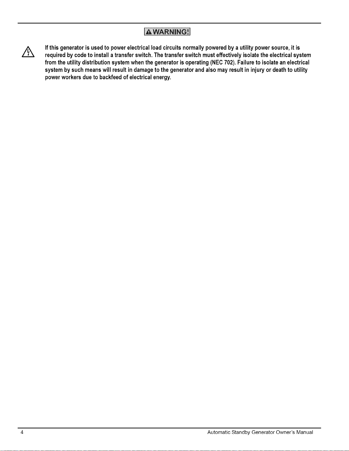
Figure 2-1" GH-410 Enqine 8kW Unit
EXHAUST
ENCLOSURE
COMPOSITE BASE
OIL FILTER
OIL FILTER
OIL FILLCAP
OIL FILL CAP
BATTERYCOMPARTMENT
CONTROL
PANEL
/
CIRCUIT
BREAKERS
/
FUEL
INLET
(BACK)
FUEL
REG ULATO R
:
BATTERYCOM PARTM ENT
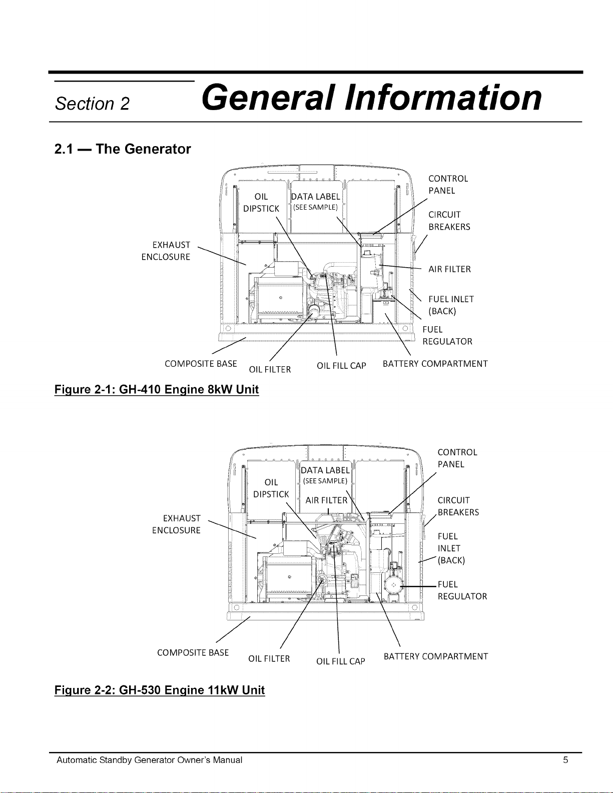
Figure 2-2:GH-530 Enqine 11kW Unit
Automatic Standby Generator Owner's Manual 5
Page 10
/
CONTROL
CIRCUIT
PANEL
BREAKERS
EXHAUST
ENCLOSURE
COMPOSITE BASE
OIL FILTER OIL FILL CAP
BATTERYCOM PARTMENT
Y
FUEL
INLET
/(BACK)
REGULATOR
\
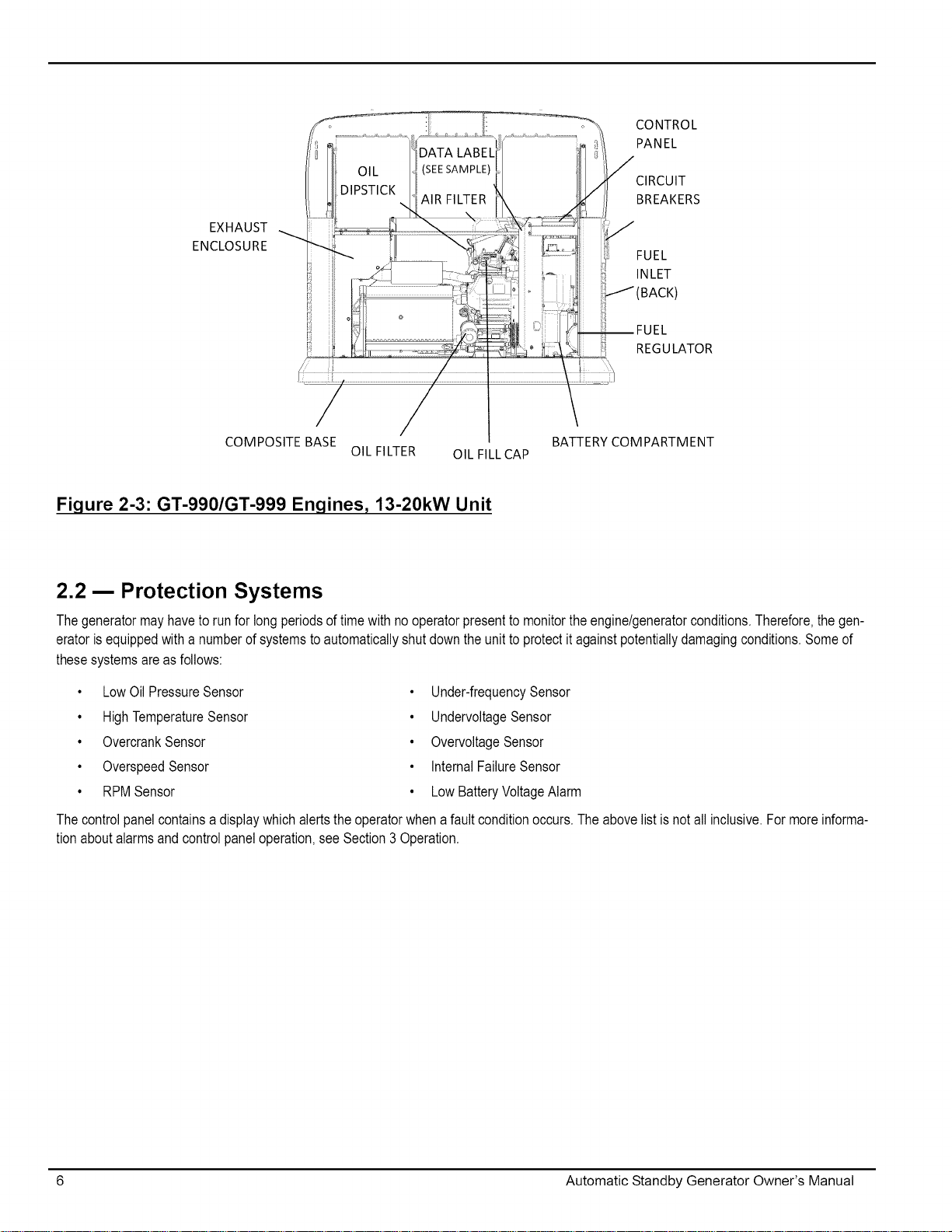
Figure 2-3:GT-990/GT-999 Enqines, 13-20kW Unit
2.2 m Protection Systems
The generator may haveto runfor long periods of time with no operator present to monitor the engine/generator conditions. Therefore, the gen-
erator is equipped with a number of systems to automatically shut down the unit to protect it against potentially damaging conditions. Some of
these systems are as follows:
• LowOil PressureSensor
• HighTemperatureSensor
• OvercrankSensor
• OverspeedSensor
• RPMSensor
The control panel contains a display which alerts the operator when a fault condition occurs. The above list is not all inclusive. For more informa-
tion about alarms and control panel operation, see Section 3 Operation.
• Under-frequency Sensor
• Undervoltage Sensor
• Overvoltage Sensor
• Internal Failure Sensor
• Low Battery Voltage Alarm
6 Automatic Standby Generator Owner's Manual
Page 11
2.3 m Emission Information
The U.S. Environmental Protection Agency (EPA)requires that this generator complywith exhaust emission standards. This generator is certified
to meet the applicable EPA emission levels, and iscertified for use as a stationary engine for standby power generation. Any other use may be a
violation of federal and/or local laws. To ensure that the engine complies with the applicable emission standards for the duration of the engine's
life, it is important to follow the maintenance specifications in the Section 4 Maintenance. This generator is certified to operate on Liquid Propane
Vaporfuel or pipeline Natural Gas.
For generators 13kWand greater, the Emission Control System code is EM (Engine Modification). The Emission Control System on this
generator consists of the following components:
• Airlnduction System
• Intake Pipe/Manifold
• Air Cleaner
• Fuel Metering System
• Carburetor/MixerAssembly
• Fuel Regulator
• Ignition System
• Spark Plug
• Ignition Module
• Exhaust System
• Exhaust Manifold
• Muffler
• Catalyst (ll kW generator only)
Automatic Standby Generator Owner's Manual 7
Page 12
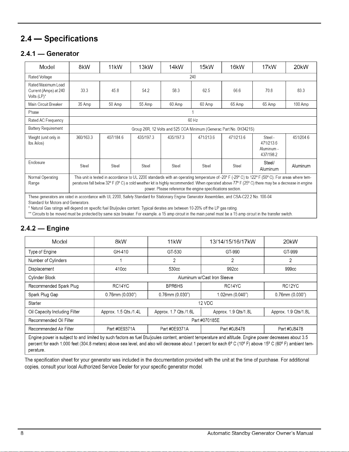
2.4 -- Specifications
2.4.1 -- Generator
Model 8kW 11kW 13kW 14kW 15kW 16kW 17kW 20kW
RatedVoltage 240
RatedMaximumLoad
Current(Amps)at240 33.3 45.8 54.2 58.3 62.5 66.6 70.8 83.3
Volts(LP)*
MainCircuitBreaker 35Amp 50Amp 55 Amp 60Amp 60Amp 65Amp 65 Amp 100Amp
Phase 1
RatedAC Frequency 60 Hz
BatteryRequirement Group26R, 12Voltsand 525CCAMinimum(GeneracPartNo.0H3421S
Weight(unitonly in 360/163.3 407/184.6 435/197.3 435/197.3 471/213.6 471/213.6 Steel- 451/204.6
Ibs./kilos) 471/213.6
Enclosure Steel/
NormalOperating Thisunit istested in accordancetoUL2200standardswithan operatingtemperatureof-200F (-29oC) to 122oF (500C). Forareaswheretem-
Range peraturesfallbelow32°F (0°C)a coldweatherkit ishighlyrecommended.Whenoperatedabove770F (250C)theremaybeadecreasein engine
These generatorsareratedin accordancewithUL2200,Safety Standardfor StationaryEngineGeneratorAssemblies,andCSA-C22.2No.100-04
Standardfor MotorsandGenerators.
* NaturalGasratingswilldependonspecificfuelBtu/joulescontent.Typicalderatesarebetween10-20%offtheLP gasrating.
** Circuitsto be movedmustbe protectedbysamesizebreaker.Forexample,a 15ampcircuitin themainpanelmustbea 15ampcircuitin thetransferswitch.
Steel Steel Steel Steel Steel Steel Aluminum
power.Pleasereferencetheenginespecificationssection.
Aluminum-
437/198.2
Aluminum
2.4.2 -- Engine
Model 8kW 11kW 13/14/15/16/17kW 20kW
Type of Engine GH-410 GT-530 GT-990 GT-999
Number of Cylinders 1 2 2 2
Displacement 410cc 530cc 992cc 999cc
Cylinder Block Aluminum w/Cast Iron Sleeve
Recommended Spark Plug RC14YC BPR6HS RC14YC RC12YC
Spark Plug Gap 0.76mm (0.030") 0.76mm (0.030") 1.02mm (0.040") 0.76mm (0.030")
Starter 12VDC
Oil Capacity Including Filter Approx. 1.5 Qts./1.4L Approx. 1.7 Qts./1.6L Approx. 1.9 Qts/1.8L Approx. 1.9 Qts/1.8L
Recommended Oil Filter Part #070185E
Recommended Air Filter Part #0E9371A Part #0E9371A Part #0J8478 Part #0J8478
Engine power is subject to and limited by such factors as fuel Btu/joules content, ambient temperature and altitude. Engine power decreases about 3.5
percent for each 1,000 feet (304.8 meters) above sea level, and also will decrease about 1 percent for each 6° C (10° F) above 15° C (60oF) ambient tem-
perature.
The specification sheet for your generator was included in the documentation provided with the unit at the time of purchase. For additional
copies, consult your local Authorized Service Dealer for your specific generator model.
8 Automatic Standby Generator Owner's Manual
Page 13
2.4.3 m Fuel Requirements
The engine has been fitted with a dual fuel carburetion system. The unit will run on natural gas or LP gas (vapor), but it has been factory set to
run on natural gas. The fuel system will be configured for the available fuel source during installation.
Recommended fuels should have a btu content of at least 1,000 Btus percubic foot (37.26 megjoules per cubic meter) for natural gas, or at least
2,500 Btus percubic foot (93.15 megajoules per cubic meter) for LP gas (vapor).
NOTE:If convertingto LPgasfrom naturalgas,a minimumLPtanksizeof250gallons(946liters) isrecommended.Seethe Installa-
tionManualfor completeproceduresanddetails.
Gaseous fuels such as natural gas and liquid propane gas are highly explosive. Even the
slightest spark can ignite such fuels and cause an explosion. No leakage of fuel is permitted.
Natural gas, which is lighter than air, tends to collect in high areas. LP gas is heavier than air
and tends to settle in low areas
2.4.4 m Battery Requirements
Group 26R, 12V,minimum 525CCA (Generac Part No.0H3421S).
For proper battery maintenance procedures, see Section 4 Maintenance.
2.4.5 -- Battery Charger
The battery charger is integrated into the control panel module in all models. It operates as a "Smart Charger" which ensures output charging lev-
els are safe and continuously optimized to promote maximum battery life.
2.4.6 _ Engine Oil Requirements
For proper oil viscosity, see chart in Figure 4-1: Recommended Oil Based on Temperature.
2.5 m Accessories
There are performance enhancing accessories available for air-cooled generators.
Accessory Description
Cold Weather Kit Recommended in areas where temperatures regularly fall below 320 F(0° C).
Scheduled Maintenance Kit Includes all pieces necessary to perform maintenance on the generator along with oil recommendations.
Auxiliary Transfer Switch Lock- Enables any of the transfer switches to completely lock out one large electrical load by tying into its control system.
out
Fascia Skirt Wrap Standard on all 20kW units. It is available for all other current production air-cooled units. It snaps together to pro-
vide a smoothing, contoured look as well as rodent/insect protection.
Mobile Link TM Provides a personalized web portal that displays the generator's status, maintenance schedule, event history and
much more. This portal is accessible via computer, tablet or smart phone. Sends emails and/or text notifications the
moment there is anychange in the generator's status. Notification settings can be customized to what type of alert is
sent and how often. For more information, visit www.standbystatus.com.
Touch-Up Paint Kit Very important to maintain the look and integrity of the generator enclosure. This kit includes touch-up paint and
instructions.
Contact a Dealer for additional information on accessories.
Automatic Standby Generator Owner's Manual 9
Page 14

This page intentionally left blank.
10 Automatic Standby Generator Owner's Manual
Page 15

Section 3
Operation
3.1 -- Control Panel
//_ The control panel on this unit is intended to only be operated by qualified service personnel.
The Control panel interface is located under the lid of the enclosure. Before attempting to lift the lid of the enclosure, verify that both left and right
side locks are unlocked. To remove the front cover, lift the cover straight up to disengage the side hooks, then tilt and lift it away from the unit.
When closing the unit, ensure that both left and right side locks are securely locked. See Figure 3-1.
The enclosed keys provided with this unitare for service personnel usage only.
Interface
SIDE LOCK
Figure 3-1" Generator With Lid Open/Side Lock Location
Set to AUTO, the engine may crank and start at any time without warning. Such automatic starting
occurs when utility power source voltage drops below a preset level or during the normal exercise
cycle. To prevent possible injury that might be caused by such sudden starts, always set to OFF and
remove the fuses before working on or around the generator or transfer switch. Then, placea "DO
NOT OPERATE" tag on the generator panel and on the transfer switch.
NOTE:Thegeneratoristo berunwithallappropriatepanelsin place,includingduringtroubleshootingbya technician.
Automatic Standby Generator Owner's Manual 11
Page 16

!
I /7 AUTO ///7 MANUALf_ OFF _./_\
Figure 3-2: Generator Control Panel
3.2 m Using the Auto/Off/Manual Buttons
Button Description of Operation
Auto Selectingthisbuttonactivatesfullyautomaticsystemoperation.Italsoallowstheunittoautomaticallystartandexercisethe
engineeverysevendayswiththesettingof theexercisetimer(seetheSettingtheExerciseTimersection).
Off Thisbuttonshutsdowntheengineand alsopreventsautomaticoperationofthe unit.
Manual Thisbuttonwillcrankandstartthe generator.Transferto standbypowerwillnotoccurunlessthereis autility
failure.
NOTE:Damagecausedby mis-wiringof theinterconnectwiresisnotwarrantable.
3.3 m Interface Menu Displays
The LCD display:
Feature Description
HOME page The default page which will bedisplayed ifno buttons are pressed for 60 seconds. This page normally shows the current Status
message and the current date and time. The highest priority active Alarm/Warning will be automatically posted on this page as
well as flashing the backlight when such a condition is detected. Inthe case of multiple Alarms/Warnings, only thefirst message
will be displayed. To clear an Alarm or Warning, press the OFF button and then press the ENTER key.
Display Backlight Normally off. Ifthe operator presses any button, the backlight will automatically light and remain on for 30 seconds.
MAIN MENU page Allows the operator to navigate to all other pages or sub-menus by using the Arrows and Enter buttons. This page can be
accessed at any time with several presses of the dedicated Escape button. Each press of the Escape button takes the operator
to the previous menu until the MAIN MENU displays. This page contains information for- History; Status; Edit; Debug.
3.3.1m Menu System Navigation
To get to the MENU, use the "Escape" button from any page. It may require pressing it many times before getting to the MENU page. Navigate to
the desired menu by using the q'/,J, buttons. When the desired menu is displayed and flashing, press the "Enter" button. See Figure 3-3.
12 Automatic Standby Generator Owner's Manual
Page 17

"11
r--
2013 EVOLUTION/SYNC2.0 HSB MENU MAP
Running Manual
Runnk_g-Utilfiy Lost
Running-Remote Start
Running-2 Wire Start
Running - Exercise
Switched Off
Stopped - Auto
Stopped - Alarm
Battery Condition
"Good" 'Inspect Battery" or "Check Battery"
Hours o0f _H_tection
Switched to "OFF" Current Date/Time
ESC 02/14/13 07:40
z:a_ /F._ MANU.II./,:::aOR = x uP ARROW = +
Run Hours (H)
00 /
DOWN ARROW = -
r--
Warning Message(s)
"Low Battery"
"Exercise Set Error"
"FIRMWARE ERROR-9"
"Fuel Pressure"
"Battery Problem"
"Charger Warning"
"Charger Missing AC"
"Overload Warnk_"
"Overload Cooldown"
"SEEPROM ABUSE"
"USB Warning"
"Download Failure"
- 1 thru 50 + - Run Log +
- 1 thru 50 + - Alarm Log +
.... Language_Language_Language_Language
÷ English ÷ + English - + Espanol - + Francais -
Fuel Selection Fuel Selection
ESC
÷ NGorLP÷ + NGorLP-
- ESC
_ENTE_
/
__ ---_Ar_ ....
ESC ..-I1_
ENTE""""""_ _ _ Access Requires Password
H Language /
+ Po_uguese -
ENTER ESC- + EXAMPLE:
Inspect Battery 200 RnHr or 12/27/13
Next Maintenance 200 RnHr or 12/27/13
and
I
Alarm Message(s)
"High Engine Temp."
"Low Oil Pressure"
"Overcrank"
"Overspeed"
"RPM Sense Loss"
"Underspeed"
"Internal Fault"
"FIRMWARE ERRQR-T'
"WIRING ERROR"
"Over Voltage"
"Under Vokage"
"Ovedoad Remove Load"
"Low Volts Remove Load"
"Stepper Over Current"
"Fuse Problem"
0198170GST-D 05/22/13
Page 1 of 4
ESC _| ÷Current2/12/13Date/Time12:22÷ ENTER _ Sefect_ Hour14 +(0-23) Select_ Mino +(0-59) Select Month_2 + (1-12) Select_ Date13 +(1-31 ) Select_ Year13+(0-99)
ESC _| Exercise Time Quiet Test Mode ? Select Hour (0-23) Select Min (o-5g) Select Day÷ 14:00Wednesday ÷ - YESorNO + - 14 + - 0 + - Wednesday +
• 1_ ESC Invalid File
;t t tE tE t /
_ f Quiet Test Mode only
FM]lware Update Firmware Update Corrupted Fife "Current:V XXXX .... Are You Sure?" When update is complete the unit returns to Install Wizard
÷ Press Enter ÷ ÷ Insert USB ÷ File Not Found "USB: V XXXX .... - Yes or No +" menu.
_ _ _... the Green "Auto" light flashes. Seq does this twice.......
I i,,c l,,Cl = l,,c l,,c l,,c....
....
on certain models "ESCAPE" to escape out of updating.
Possible Message(s) Durh_g update process the Blue "Manuar r light fiashesr then
Unsupported Device When the controller powers up the very first screen displays
Select "Yes" then Press "Enter" to continue or Press
the version number for a few secot_ds.
When update is complete remove Thumb Ddve, then follow
the Install Wizard Menu.
Page 18

3.4 m Automatic Transfer Operation
Toselect automatic operation:
1. Make sure the transfer switch main contacts are set to their UTILITY position (loads connected to the utility power
source).
2. Be sure that normal UTILITY power source voltage is available to transfer switch terminal lugs N1 and N2.
3. Press the AUTO button on the Control Panel Interface.
4. Set the Main Circuit Breaker (Generator Disconnect) to its ON (Closed) position.
With these steps complete, the generator will start automatically when utility source voltage drops below a preset level. After the unit starts, loads
are transferred to the standby power source.
3.4.1m Automatic Sequence of Operation
3.4.1.1 m Utility Failure
With the generator set toAUTO, when the utilityfails (below 65% of nominal) a 10second (optionally programmable) line interrupt delay time is
started. If the utility is still gone when the timer expires, the engine will crank and start. Once started, a 5 second engine warm-up timer will be ini-
tiated. When the warm-up time expires, the controller will transfer the load to the generator. If the utility power is restored (above 75% nominal) at
any time from the initiation of the engine start until the generator is readyto accept load (5 second warm-up time has not elapsed), the controller
will complete the start cycle and run thegenerator through its normal cool down cycle, however, the load will remain on the utility source.
3.4.1.2 m Cranking
The system will control the cyclic cranking as follows:
8kW unit- 5 cranking cycles as follows: 15 second crank, seven (7) second rest, followed by four (4) additional cycles of seven (7) second
cranks followed by seven (7) second rests.
11-20kW units - 5 cranking cycles asfollows: 16second crank, seven (7) second rest, 16 second crank, seven (7) second rest,followed by
three (3) additional cycles of seven (7) second cranks followed by seven (7) second rests.
3.4.1.3 _ Load Transfer
Thetransferof loadwhenthegeneratorisrunningisdependentupontheoperatingmode:
MANUAL
AUTO
EXERCISE
• Will not transfer to generator if utility is present
• Wilt transfer to generator if utility fails (below 65% of nominal for 10 consecutive seconds)
• Wilt transfer back when utility returns for 15 consecutive seconds The engine will continue to run
until removed from the MANUAL mode
• Will start and run if utility fails for 10 consecutive seconds (factory default)
• Will start a 5 second engine warm-up timer
•Wilt not transfer if utility subsequently returns
•Wilt transfer to generator if utility is not present
• Will transfer back to utility once utility returns (above 75% of nominal) for 15 seconds
• Will not transfer back to utility unless utility returns The generator will shut down if the OFF button is
pressed or a shutdown alarm is present
• Once utility power is returned, the generator will shut down after 1 minute cool-down time
• Wilt not exercise if generator is already running in either AUTO or MANUAL mode
• During exercise, the controller will only transfer if utility fails during exercise for 10 seconds, and will
switch to AUTO
14 Automatic Standby Generator Owner's Manual
Page 19

3.5 m Turning the Generator Off When Operating Under Load
NOTE:Important!Toturn thegeneratoroffduringprolongedutility outagesto performmaintenanceor conserve
fuel, follow these simple, but importantsteps:
ToturnthegeneratorOFF(whilerunninginAUTOandonline):
1. Turn OFF (or OPEN) the main Utility disconnect.
2. Turn OFF (or OPEN) the Main Line Circuit Breaker (MLCB) on the generator.
3. Turn the generator OFF.
ToturnthegeneratorbackON:
1. Put the generator back into AUTO and allow to start and warm-up for a few minutes.
2. Turn ON (or CLOSE) the MLCB on the generator.
Thesystemwillnow beoperatinginitsautomaticmode.ThemainutilitydisconnectcanbeturnedON (orCLOSED),buttoshuttheunitoff,this
completeprocessmust berepeated.
3.6 m Manual Transfer Operation
DO NOT attempt to activate the transfer switch manually until all powervoltage supplies to the switch have been
completely turned off. Failureto turn off all powervoltage supplies may result in extremely hazardous and possi-
bly fatal electrical shock.
Prior to automatic operation, manually exercise the transfer switch to verify that there is no interference with proper operation of the mechanism.
Manual operation of the transfer switch is required if electronic operation should fail.
3.6.1m Transfer to Generator Power Source
,
Press the Control Panel OFF button.
2.
Set the Main Circuit Breaker (Generator
LOAD CONNECTED TO UTILITY POWER SOURCE
LOAD CONNECTED TO STANDBY POWER SOURCE
MANUAL TRANSFER
HANDLE
TRANSFER SWITCH
OPERATING LEVER
Disconnect) to its OFF (OPEN) position.
,
Turn off the utility power supply to the transfer
switch using the means provided (such as a utility
main line circuit breaker).
,
Use the manual transfer handle inside the transfer
switch to move the main contacts to their STANDBY
positions (loads connected to the standby power
souroe).
,
To crank and start the engine, press the Control
Panel MANUAL button.
6.
Allow the engine to stabilize and warm up for a few
minutes.
7.
Set the Main Circuit Breaker (Generator
Disconnect) to its ON (CLOSED) position. The
standby power source now powers the loads.
Figure 3-4: Manual Transfer Switch Operation
Automatic Standby Generator Owner's Manual 15
Page 20

3.6.2-- Transfer Back to Utility Power Source
When utility power has been restored, transfer back to utility source and shut down the generator. To manually transfer back to utility power and
shut down the generator:
1. Set the Main Circuit Breaker (Generator Disconnect) to its OFF (OPEN) position.
2. Allow the engine to run for 2 minutes at no-load to stabilize the internal temperatures.
3. Press the Control Panel OFF button. The engine should shut down.
4. Ensure that utility power supply to the transfer switch is turned off.
5. Use the manual transfer handle inside the transfer switch to move the main contacts back to their UTILITY posi-
tions (loads connected to the utility power source).
6. Turn on the utility power supply to the transfer switch using the means provided.
7. Press the Control Panel AUTO button.
3.7 -- Side Compartment
Local codes may require this compartment to be locked. A hasp is provided so the owner/operator can secure the compartment with his or her
own padlock. Check local codes for side compartment locking requirements.
LEDINDICATOR LIGHTS
120V GFCI OUTLET MAIN CIRCUIT BREAKER
15 Amp OUTLET BREAKER
Figure 3-5: Open Side Compartment
3.7.1-- Main Circuit Breaker (Generator Disconnect)
This is a 2-pole breaker rated according to relevant specifications.
3.7.2-- LED Indicator Lights
• Green LED "Ready" light is on when utility is present and the Control Panel button is in the AUTO position. This also indicates when thegen-
erator is running.
• Red LED"Alarm" light is on when the generator is OFF or a fault is detected and means contact your authorized servicing dealer.
• Yellow LED "Maintenance" light. Note: Yellow LED may be on at the same time as either the Red or Green LEDs.
16 Automatic Standby Generator Owner's Manual
Page 21

3.7.3m 120V GFCI Outlet/15 Amp Breaker (17 & 20 kW Only)
All units are equipped with an external 15 amp, 120 volt GFCI convenience outlet located inthe top corner of the compartment.
When the generator is running, in the absence of utility power, this outlet may also be used to power items outside the home such as lights or
power tools. This outlet may also be used when utility power is present by running the generator in manual mode.
This outlet does not provide power if the generator is not running. Do not use this outlet when the generator is in Exercise mode. This outlet is
protected by a 15amp circuit breaker in the side compartment.
3.8 m Alarm Response Procedures
The generator is protected by a series of sensors that will detect an Alarm/Warning condition and alert the owner/operator of the condition via the
Control Panel display.When certain alarm conditions are detected, the generator will shut down.
Alarm/Warning conditions can include (this is not a complete list):
• Low Oil Pressure
• High Engine Temperature
• Low Battery
• Under-voltage
• Exercise Set Error
NOTE:Unlessproperlytrainedto clearandcorrectWarningandAlarmconditions,contactthe nearestAuthorizeddealerorTrained
Technician.
3.9 m Battery Charger
NOTE: The battery charger is integrated into the control module in all models.
The battery charger operates as a "Smart Charger" that ensures:
• Output is continually optimized to promote maximum battery life.
• Charging levels are safe.
NOTE:A warningisdisplayedonthe LCDwhenthe batteryneedsservice.
3.10 Setting the Exercise Timer
Thisgeneratorisequippedwith anexercisetimer.Onceit isset, thegeneratorwillstartandexerciseeverysevendays,onthedayoftheweekandatthetimeofday
specified.Duringthis exerciseperiod,theunitrunsforapproximately12minutesandthenshutsdown. Transferof loadsto thegeneratoroutputdoesnotoccurduring
theexercisecycleunlessutilitypowerislost.
Theexercisesettingscanbechangedat anytime via the"EDIT"menu.
If the 12 volt batteryis disconnectedor the fuseremoved,theInstallationWizardwill operateuponpowerrestoration.Theonlydifferenceisthedisplaywillonly
promptthecustomerforthecurrentTimeandDate.
Theexerciserwill onlyworkintheAUTOmodeandwill notwork unlessthis procedureis performed.Thecurrentdatettimewill needtoberesetevery timethe12
voltbatteryis disconnectedandthenreconnected,and/orwhenthefuse is removed.
Automatic Standby Generator Owner's Manual 17
Page 22

This page intentionally left blank.
18 Automatic Standby Generator Owner's Manual
Page 23

Section 4
Maintenance
NOTE:Propermaintenanceandproperandsafeoperationiscrucialtothelifeof thegenerator.GenuineGeneracpartsMUSTbe used
toensurewarrantycoverage.
NOTE:Sincemostmaintenancealertswilloccuratthesametime (mosthavetwoyearintervals),onlyonewillappearontheControl
Paneldisplayat anyonetime.Oncethe first alertis cleared,thenextactivealertwillbe displayed.
/_AII service to this generator must be performed by a qualified service person only.
4.1 m Performing Scheduled Maintenance
It is important to perform Maintenance as specified in the Service Schedule for proper generator operation and to ensure that the generator com-
plies with the applicable emission standards for the duration of its useful life. Service and repairs may be performed by any qualified service per-
son or repair shop. Additionally, emissions critical maintenance must be performed as scheduled in order for the Emissions Warranty to be valid.
Emissions critical maintenance consists of servicing the air filter andspark plugs in accordance with the Service Schedule. The controller will
prompt for Schedule A or Schedule Bmaintenance to be performed. Schedule A maintenance consists of the oil, oil filter and tune-up. Schedule
B maintenance includes the oil, oil filter, tune-up, air cleaner, spark plug(s) and valve clearance.
4.2 m Service Schedule
ATTENTION: All service work must be performed bya qualified service person only.
System Component Procedure Frequency
X = Action W =Weekly
R= Replace as Necessary Inspect Change Clean M = Monthly
* = Notify Dealer if Repair is Needed Y = Yearly
Fuel
Fuel,nesandconnect,ons* 1 X 1 l 1 M
Lubrication
Oil level X M or 24 hours of continuous operation
Oil X 2Y or 200 hours of operation**
Oil filter X 2Y or 200 hours of operation**
Cooling
Enclesureleuvers 1 x 1 l x 1 w
Battery
Remove corrosion, ensure dryness
Clean and tighten battery terminals
Check charge state
Electrolyte level (unsealed batteries only)*
Engine and Mounting
Air cleaner
Spark plug(s)
Valve Clearance
General Condition
Vibration, Noise, Leakage*
Complete Tune-Up*
* Contact the nearest Dealer for assistance if necessary.
** Change oil and filter after the first 25 hours of operation. Continue to check at intervals of 200 hours or 2 years, whichever occurs first. Severe duty oil drain inter-
vals: In cold weather conditions (ambient below 40°F/4.4°C) change engine oil and filter every year or 100 hours of operation to prevent accumulation of water in
the oil. If the unit will be operated continuously in hot ambient conditions (ambient above 85°F/29.4°C) or operation in an extremely dusty or dirty environment
change the engine oil and filter every year or 100 hours of operation to prevent oil breakdown.
*** Check valve clearance after the first 25 hours of operation. Continue to check at intervals of 400 hours.
X X Y
X X Y
X X Y
X X Every 6 M
X X 400 hours
X X 400 hours
X 500 hours***
x 1 l M
To be completed by a Dealer 2Y or 200 hours
Automatic Standby Generator Owner's Manual 19
Page 24

4.2.1m Maintenance Log
1. Battery inspection and charge check (recommended every year (1) for the life of the battery)
NOTE: Check electrolyte level (unsealed batteries only) every 6 months.
Dates Performed:
2. Oil, oil filter and air filter replacement (recommended after the first 25 hours after installation and every 200 hours or 2years, whichever
occurs first) NOTE: Spark plug replacement (recommended every 4 years or 400 hours, whichever occurs first).
Dates Performed:
3. Valve Adjustment (recommended after the first 25 hours of operation and then after every 400 hours of operation)
Dates Performed:
4.3 m Checking Engine Oil Level
When power outages necessitate running the generator for extended periods, the oil level should be checked daily. Tocheck the engine oil level:
1. Ifthe generator is running during a utility outage, first turn OFF all associated loads running inthe residence usingthe electrical panel's main
disconnect. Then, turn the generator's Main Circuit Breaker to the OFF position.
2. Press the Control Panel OFF button. Wait 5 minutes.
3. Remove the dipstick and wipe it dry with a clean cloth.
4. Completely insert the dipstick and again remove it.
5. Observe the oillevel. The level should be at the "Full" mark on the dipstick.
6. If necessary, remove the oil fill cap and add oil to the engine until the level reaches the "Full" mark and reinsert the dipstick and fill cap.
7. Press the Control PanelAUTO button.
8. Ifthe generator was running during a utility outage, first turn the Main Circuit Breaker to the ON position. Then, turn ON the needed loads in
the residence.
Never operate the engine with the oil level below the "Add" mark onthe dipstick. Doingso could damage the
engine.
Hot oil may cause burns. Avoid prolonged or repeated skin exposure with used oil. Thoroughly wash exposed
areas with soap.
20 Automatic Standby Generator Owner's Manual
Page 25

4.3.1m Engine Oil Recommendations
Tomaintain the warranty, genuine Generac replacement parts MUST be used, including Generac oil kits (which include an oil andair filter). Gen-
erac oil kits can be obtained through an Authorized Dealer or purchased on-line. To purchase on-line, access the maintenance kits page through
www.generac.com or directly at shop.generac.com Follow the prompts to enter delivery information and complete the purchase.
All Generac oil kits meet minimum American Petroleum institute (API) Service Class SJ, SL, or better. Use no special additives. Select the appro-
priate viscosity oil grade according to the expected operating temperature. Synthetic oil also can be used in the appropriate weight as standard.
100
40
Figure 4-1: Recommended Oil Based on Temperature
• SAE 30 above 320 F(0 °C)
• 10W30 between 400and -100 F (40and -230C)
• Synthetic 5W 30 for all temperature ranges
Any attempt to crank or start the engine before it has been properly serviced with the recommended oil may
result in an engine failure.
4.3.2m Changing the Oil and Oil Filter
1. Start the engine by pressing the MANUAL button on thecontrol panel and allowthe engine to run until it is thoroughly warmed up. Then,
press the Control Panel OFF button to shut down the engine.
2. A few minutes after the engine shuts OFF,when it has cooled slightly, lift thelid and remove the front panel. Pullthe oil drain hose free of its
retaining clip. Remove the cap from the hose and drain the oil into a suitable container.
3. After the oil has drained, replace the cap onto the end of the oil drain hose. Reposition and secure the hosewith the retaining clip.
4. With the oil drained, remove the old oil filter by turning it counterclockwise. For filter location, see Figure 4-2.
5. Apply a light coating of clean engine oil to the gasket of the new filter.
6. Screw the newfilter on by hand until its gasket lightly contacts the oil filter adapter. Then, tighten the filter an additional 3/4 to one full turn.
7. Refill the engine with the proper recommended oil. For recommended oil, see Figure 4-1.
8. Start the engine, run for 1minute, and check for leaks.
9. Shutdown the engine and recheck the oil level. Add oil as needed. DO NOT OVER FILL.
10. Re-insert dipstick and/or reattach fill cap.
11. Press the Control Panel AUTO button.
12. Dispose of the used oil and filter at a proper collection center.
Automatic Standby Generator Owner's Manual 21
Page 26

Figure 4-2: Oil Filter and Drain Location
4.4 m Changing the Engine Air Cleaner
1. With the generator shut down, lift the lid and remove the front panel.
2. Remove the cover clips and air cleaner cover (11-20kW), or disengage the wire clip and open the air cleaner access door (8kW).
3. Pull outthe old air filter and discard.
4. Thoroughly clean the air cleaner enclosure of any dust or debris.
5. Install a new air cleaner.
6. Install the air cleaner cover and cover clips (11-20kW),or close the air cleaner access door and engage the wire clip (8kW).
4.5 m Spark Plugs
Reset the spark plug(s) gap or replace the spark plug(s) as necessary:
1. With the generator shut down, lift the lid and remove the front panel.
2. Clean the area around the base of the spark plug(s) to keep dirt anddebris out of the engine.
3. Remove the spark plug(s) and check the condition. Install a new plug(s) if the old one is worn or if reuse is questionable.
4. Clean the plug(s) by scraping or washing with a wire brush and commercial solvent. Do not blast the plug(s) to clean.
5. Check the spark plug gap using awire feeler gauge. See Figure 4-3. Adjust thegap by carefully bending the ground electrode to:
• For 8, 11,and 20kW units - 0.76 mm (0.030 inch)
• For 13, 14, 15, 16, 17kW units - 1.02 mm (0.040 inch)
Figure 4-3: Spark Plug Gap Adjustment
22 Automatic Standby Generator Owner's Manual
Page 27

4.6 m Valve Lash Adjustment
After the first 25 hours of operation and then at every 400 hour interval afterwards, check the valve clearance. Adjust if necessary.
Important: Please contact the Dealer for service assistance. This is a very important step to ensure longest lifefor the engine.
Tocheck valve clearance:
• The engine should be cool before checking. If valve clearance is 0.002" - 0.004" (0.05 - 0.1mm), adjustment is not needed.
• Remove spark plug wires and position wires away from plugs.
• Remove spark plugs.
• Make sure thepiston is at TopDead Center (TDC) of its compression stroke (both valves closed). Toget the piston at TDC, remove the intake
screen at the front of the engine to gainaccess to the flywheel nut. Use a large socket and socket wrench to rotate the nutand hence the
engine in aclockwise direction. While watching the piston through the spark plug hole.The pistonshould move up and down. The piston is at
TDC when it is at its highest point of travel.
Toadjust valve clearance (see Figure 4-4):
• Make sure the engine is at 60° to 80° F (16° to 27° C).
• Make sure that the spark plugwire is removed from the spark plug and out of the way.
• Remove the four screws attaching the valve cover.
• Loosen therocker jam nut. Using a 10ramAllen wrench (530cc engine) or a 13ramAllen wrench (410cc, 990cc and 999cc engines), turn the
pivot ball stud while checking clearance between the rocker arm and the valve stemwith a feeler gauge. Correct clearance is 0.002-0.004
inch (0.05-0.1 mm).
NOTE: Hold the rocker arm jam nut in placeas the pivot ball stud is turned.
• When valve clearance iscorrect, hold the pivot ball stud in place with the Allen wrench and tighten the rocker arm jam nut. Tighten the jam nut
to 174 in-lbs. (19.68 N-m) torque. After tightening the jam nut, recheck valve clearance to make sure it did not change.
• Install new valve cover gasket.
• Re-attach the valve cover.
NOTE: Start all four screws before tightening or it will not be possible to get all the screws in place. Make sure the valve cover gasket
is in place.
• Install spark plugs.
• Re-attach the spark plug wire to the spark plug.
• Repeat the process for theother cylinder, if necessary.
Automatic Standby Generator Owner's Manual 23
Page 28

Pivot Ball
Stud
Jam Nut
Figure 4-4: Valve Clearance Adjustment
4.7 m Battery Maintenance
The battery should be regularly inspected per the Service Schedule:
Rocker
Arm
Valve
Stem
1. With the generator shut down, lift the lid and remove the front panel.
2. Inspect the battery postsand cables for tightness and corrosion. Tighten and clean as necessary.
3. Check the battery fluid level of unsealed batteries, and if necessary, fill with distilled water only. DO NOT use tap water. Also, have the
Dealer or a qualified Service Technician check the state of charge and condition.
Do not dispose of the battery by incineration. The battery is capable of exploding.
A battery presents a risk ofelectrical shock and high short circuit current. Strictly observe the following precau-
Z_ tionswhen working on batteries:
Remove the 7.5 Amp fuse from the generator control panel.
Remove all jewelry--watches, rings, metal objects, etc.
Use tools with insulated handles.
Wear rubber gloves and boots.
Do not lay tools or metallic objects on top of the battery.
Disconnect the charging source prior to connecting or disconnecting battery terminals.
24 Automatic Standby Generator Owner's Manual
Page 29

Do not open or mutilate the battery. Releasedelectrolyte has been knownto be harmful to theskin and eyes, and
to be toxic. The electrolyte is a dilute sulfuric acid that is harmful to the skin and eyes. It is electrically conduc-
tive and corrosive. Strictly observethe following precautions:
• Wear full eye protection and protective clothing.
• Where electrolyte contacts the skin, wash it off immediately with water.
• Where electrolyte contacts the eyes, flush thoroughly and immediately with water and seek medical attention.
• Wash down spilled electrolyte with an aid neutralizing agent. A common practice is to use asolution of 1 pound (500 grams) bicarbonate
of soda to 1 gallon (4 liters) of water. The bicarbonate of soda solution is to be added until the evidence of reaction (foaming) has
ceased. The resulting liquid is to be flushed with water and the area dried.
Lead-acid batteries present a risk offire because they generate hydrogen gas. Strictly observe the following pre-
_ cautions:
• DO NOT smoke when near the battery.
• DO NOT cause flame or spark in the battery area.
• Discharge static electricity from the body before touching the battery byfirst touching a grounded metal surface.
Besure the utility powersupply is turned off and the 7.5Amp fuse is removedfrom the generator Control Panel,
_, or sparking may occur battery posts as are cause an explosion.
at the the cables attached and
4.8 m Attention After Submersion
If the generator has been submerged in water, it MUST NOT be started and operated. Following any submersion in water, havea Dealer thor-
oughly clean, dry, and inspect the generator. If the structure (home) has been flooded, it should be inspected by a certified electrician to ensure
there won't be any electrical problems during generator operation or when utility power is returned.
4.9 m Corrosion Protection
Periodically wash and wax the enclosure using automotive type products. Frequent washing is recommended in salt water/coastal areas. Spray
engine linkages with a light oil such as WD-40.
4.10 Out of Service Procedure
4.10.1m Removal From Service
If the generator cannot be exercised every 7 days and will be out of service longer than 90 days, prepare the generator for storage:
1. Start the engine and let it warm up.
2. Close the fuel shutoff valve in the fuel supply line and allow the unit to shut down.
3. Once the unit has shut down, set the generator's Main Circuit Breaker (Generator Disconnect) to its OFF (OPEN) position.
4. Turnoff the utility power to the transfer switch.
5. Remove the 7.5 Amp fuse from the generator's Control Panel.
6. Disconnect the battery cables. Remove negative cablefirst.
7. Remove battery charger AC input Tl/Neutral cable (has white sleeve) at controller.
8. While the engine is still warm, drain the oil completely, and then refill the crankcase with oil.
9. Attach a tag to the engine indicating the viscosity and classification of the new oil inthe crankcase.
10. Remove the spark plug(s) and spray a fogging agent into the spark plug(s)' threaded openings. Reinstall and tighten the spark plug(s).
Automatic Standby Generator Owner's Manual 25
Page 30

11.Removethebatteryandstoreitinacool,dryroomonawoodenboard.Neverstorethebatteryonanyconcreteorearthenfloor.
12.Cleanandwipedowntheentiregenerator.
4.10.2m Return to Service
Toreturn the unit to service after storage:
1. Verify that utility power is turned off.
2. Check the tag on the engine for oil viscosity and classification. Ifnecessary, drain and refill with proper oil.
3. Check the state of the battery. Fill all cells of unsealed batteries to the proper level with distilled water. DO NOT use tap water. Recharge the
battery to 100% state of charge, if defective, replace thebattery.
4. Clean and wipe down the entire generator.
5. Make sure the 7.5 Amp fuse is removed from the generator Control Panel.
6. Reconnect the battery. Observe battery polarity. Damage may occur if the battery is connected incorrectly. Install positive cable first.
7. Reconnect the battery charger AC input T1/Neutral cable (has white sleeve) at controller.
8. Open the fuel shutoff valve.
9. Insert the 7.5 Amp fuse into the generator Control Panel.
10. Start the unit by pressing the MANUAL button. Allow the unit to warm up for afew minutes.
11. Stop the unit by pressing the Control Panel OFF button.
12. Turnon the utility power to the transfer switch.
13. Set the Control Panel to AUTO.
The generator is ready for service.
NOTE:Whenabatteryisdeador hasbeendisconnected,theexercisetimerandcurrentdateandtimemustbereset.
26 Automatic Standby Generator Owner's Manual
Page 31

Section 5
Troubleshooting
Problem
The engine will not crank.
The engine cranks but
will not start.
The engine starts hard
and runs rough.
Cause Correction
1. Fuse blown.
2. Loose, corroded or defective
battery cables.
3. Defective starter contact.
4. Defective starter motor.
5. Dead Battery.
1. Out of fuel.
2. Defective fuel solenoid (FS).
3. Open #14 wire from engine control
board.
4. Defective spark plug(s).
5. Valve lash out of adjustment.
1. Air cleaner plugged
or damaged.
2. Defective spark plug(s).
3. Fuel pressure incorrect.
4. Fuel selector in wrong position.
1. Correct short circuit condition by
replacing 7.5 Amp fuse in generator
control panel.
2. Tighten, clean or replace
as necessary.*
3. *See #2.
4. *See #2.
5. Charge or replace battery.
1. Replenish fuel/Turn on fuel valve.
2. *
3. Repair wiring.
4. Clean, re-gap or replace plug(s).
5. Reset valve lash.
1,
Check/replace air cleaner.
2.
Clean, re-gap or replace plug(s).
3.
Confirm fuel pressure to regulator
is 10-12" water column (19-22mm
mercury) for LP, and 3.5-7" water
column (7-13mm mercury) for
natural gas.
4,
Move selector to correct position.
The generator is set to OFF,
but the engine continues to
run.
There is no AC output from
the generator.
There is no transfer to
standby after utility
source failure.
Unit consumes large
amounts of oil.
*Contact an Authorized Service Dealer for assistance.
1. Controller wired incorrectly
2. Defective control board.
1. Main line circuit breaker is in
the OFF (or OPEN) position.
2. Generator internal failure.
1. Main line circuit breaker is inthe OFF
(or OPEN) position..
2. Defective transfer switch coil.
3. Defective transfer relay.
4. Transfer relay circuit open.
5. Defective control logic board
1. Engine over filled with oil.
2. Engine breather defective.
3. Improper type or viscosity of oil.
4. Damaged gasket, seal or hose.
1. Repair wiring or replace controller.
2. *
1. Reset circuit breaker
to ON (or CLOSED).
2. *
1. Reset circuit breaker to ON
(or CLOSED) position.
2. *
3. *
4. *
5. *
1. Adjust oil to proper level.
2. *
3. See "Engine Oil
Recommendations".
4. Check for oil leaks.
Automatic Standby Generator Owner's Manual 27
Page 32

This page intentionally left blank.
28 Automatic Standby Generator Owner's Manual
Page 33

Section 6
Quick Reference Guide
Problem LED Things to
Unit running in AUTO but no power GREEN Check MLCB. NONE Check MLCB. Contact servicing dealer if
in house. MLCB is in the ON position.
Unit shuts down during operation. RED LEDs/Screen TEMPERATURE exhaust and rear of generator. Contact
Unit shuts down during operation. RED LEDs/Screen REMOVE LOAD loads from the generator. Put back in
Unit was running and shuts down,
attempts to restart.
Unit will not start in AUTO with utility NONE says unit not ACTIVATED Manual.
loss. activated.
Unit will not start in AUTO with utility GREEN for start delay None expected, contact servicing dealer to
loss. countdown, adjust from 2 to 1500 seconds.
Unit will not start in AUTO with utility RED LEDs/Screen Manual. Contact servicing dealer if oil
loss. for alarms. PRESSURE level is correct.
Unit will not start in AUTO with utility
loss.
Unit will not start in AUTO with utility
loss.
Unit will not start in AUTO with utility RED LEDs/Screen LOW VOLTS
loss. for alarms. REMOVE LOAD
Unit will not start in AUTO with utility RED LEDs/Screen FUSE PROBLEM same type fuse if bad. Contact servicing
loss. for alarms, dealer if fuse is good.
Unit will not start in AUTO with utility RED LEDs/Screen OVERSPEED Contact servicing dealer.
loss. for alarms.
Unit will not start in AUTO with utility RED LEDs/Screen VOLTAGE
loss. for alarms.
Unit will not start in AUTO with utility RED LEDs/Screen UNDERSPEED Contact servicing dealer.
loss. for alarms.
RED
RED
Check Active Alarm Solution
Check the Check ventilation around the intake,
for alarms, serving dealer if no obstruction is found.
Check the Clear alarm and remove household
for alarms. AUTO and restart.
Check the
LEDs/Screen
for alarms.
See if screen
Check screen If the start up delay is greater than
Check the LOW OIL Check oil level. Add oil per Owner's
Check the
LEDs/Screen
for alarms.
Check the
LEDs/Screen
for alarms.
Check the
Check the Check ATO 7.5 amp fuse. Replace with
Check the
Check the
Check the
HIGH
OVERLOAD
Clear alarm and remove household
RPM SENSE
LOSS
NOT Refer to activation section in Owner's
RPM SENSE
LOSS
OVERCRANKRED
UNDER Contact servicing dealer.
loads from the generator. Put back in
AUTO and restart, tf problem returns,
contact servicing dealer to investigate
possible fuel issue.
Clear alarm. From the MAIN menu on
the control panel, navigate to the BAT-
TERY MENU. Contact servicing dealer if
battery is GOOD. Replace battery If
CHECK BATTERY is displayed.
Check fuel line shutoff valve is in the ON
position. Clear alarm. Attempt to start
the unit in MANUAL. If it does not start
or starts and runs rough, contact servic-
ing dealer.
Clear alarm and remove household
loads from the generator. Put back in
AUTO and restart.
Automatic Standby Generator Owner's Manual 29
Page 34

Problem LED Things to
Unit will not start in AUTO with utility RED LEDs/Screen OVERCURRENT
loss. for alarms.
Unit will not start in AUTO with utility RED LEDs/Screen MISWIRE Contact servicing dealer.
loss. for alarms.
Unit will not start in AUTO with utility RED LEDs/Screen OVERVOLTAGE Contact servicing dealer.
loss. for alarms.
Yellow LED illuminated in any state.
Yellow LED illuminated in any state. YELLOW for additional PROBLEM Contact servicing dealer.
Yellow LED illuminated in any state, for additional WARNING Contact servicing dealer
Yellow LED illuminated in any state. YELLOW for additional SERVICE A
Yellow LED illuminated in any state. YELLOW for additional SERVICE B
Yellow LED illuminated in any state. YELLOW for additional Inspect Battery Inspect battery; press ENTER to clear.
YELLOW
YELLOW Check screen CHARGER
Check Active Alarm Solution
Check the
STEPPER Contact servicing dealer.
Check the
Check the
Clear alarm. From the MAIN menu on
Check screen
for additional
information.
Check screen
information.
information.
Check screen
information, press ENTER to clear.
Check screen
information, press ENTER to clear.
Check screen
information.
LOW BATTERY
BATTERY
the control panel, navigate to the BAT-
TERY MENU. Contact servicing dealer if
battery is GOOD. Replace battery If
CHECK BATTERY is displayed.
Perform SERVICE A maintenance;
Perform SERVICE B maintenance;
30 Automatic Standby Generator Owner's Manual
Page 35

Page 36

U,S, EPA EMiSSiON CONTROL WARRANTY STATEMENT
YOUR WARRANTY RIGHTS AND OBLiGATiONS
TheUnitedStatesEnvironmentalProtectionAgency (EPA)and GeneracPowerSystems, Inc. (Generac)are pleasedto explainthe EmissionControl
SystemWarranty (ECSWarranty)on your new 2011 andlater equipment.New equipmentthatuse smallspark-ignitedenginesmust be designed,built,
andequippedto meet stringentanti-smogstandardsfor the federalgovernment.Generacwill warrantthe emission control system on your equipment
for theperiod of time listed below providedthere has beenno abuse,neglect,unapprovedmodificationor improper maintenanceof your equipment.
Theemissioncontrol system onthis equipmentincludes all components whosefailure would increasethe emissions of anyregulatedpollutant. These
componentsare listedin the EmissionsInformation section of this manual.
MANUFACTURER'S WARRANTY COVERAGE:
This ECSWarrantyis valid fortwo years,or for the same periodas specified in the GeneracLimitedWarranty,whicheveris longer.Forequipmentwith
hour meters,the warranty period is a number of hours equalto halfthe UsefulLifeto which the equipmentis certified, or the warrantyperiod specified
abovein years,whichever is less. TheUsefulLife can befound onthe EmissionControl Labelon the engine.If, during such warrantyperiod, any
emission-relatedpart on your equipmentis found to be defectivein materials orworkmanship, repairs or replacementwill be performedby a Generac
AuthorizedWarrantyServiceDealer.
OWNER'S WARRANTY RESPONSiBiLiTiES:
Astheequipmentowner,you are responsibleforthe completion of all requiredmaintenanceas listed inyour factory suppliedOwner'sManual. For
warrantypurposes,Generacrecommendsthat you retainall receiptscovering maintenanceon your generator,but Generaccannot denywarranty
solelydue tothe lack of receipts.
You shouldbe awarethat Generacmay deny anyand/or all warranty coverageor responsibilityif your equipment,or a part!componentthereof, has
failed dueto abuse,neglect, impropermaintenance,or unapprovedmodifications.
Youare responsible for contactinga GeoeracAuthorizedWarranty Dealer as soonas a problemoccurs.Thewarranty repairsshouldbe
completed in a reasonable amount of time, not to exceed 30 days.
Warrantyservice can be arrangedby contactingeitheryour sellingdealeror aGeneracAuthorizedWarrantyServiceDealer.Tolocate the Generac
AuthorizedWarrantyServiceDealernearestyou, call our tollfree numberbelow,or email emissions@generac.com.
1-800-333-1322
IMPORTANTNOTE:Thiswarranty statementexplainsyour rightsand obligationsunderthe EmissionControl SystemWarranty,which is providedto
you byGeneracpursuantto federal law.Seealsothe "GeneracLimitedWarrantiesfor GeneracPower Systems, Inc.,"which is enclosed herewithon a
separatesheet,also providedto you by Generac.Notethatthis warranty shall not applyto any incidental,consequentialor indirect damagescaused
bydefects inmaterials or workmanship or any delayin repair or replacementof the defectivepart(s). This warranty is in place of all other warranties,
expressedor implied. Specifically,Generacmakes no other warrantiesasto the merchantabilityor fitness for a particularpurpose. Anyimplied
warrantieswhich are allowedby law, shall be limited indurationto the terms ofthe expresswarranty provided herein.Some statesdo not allow
limitationson how long an impliedwarranty lasts, so the abovelimitationmay not apply to you.
TheECSWarrantyappliesonly to the emission control systemof your new equipment.Both theECSWarrantyandthe GeneracWarrantydescribe
importantrights and obligationswith respectto your new engine.
Warrantyservice can be performed only by a GeneracAuthorizedWarrantyService Facility.Whenrequestingwarrantyservice, evidencemust be
presentedshowing the dateof the saleto the originalpurchaser/owner.
Ifyou haveany questionsregardingyour warranty rightsand responsibilities,you shouldcontact Generacatthe following address:
ATTENTION WARRANTY DEPARTMENT
GENERAC POWER SYSTEMS, INC.
P.O. BOX 297 oWHITEWATER, Wi 53190
PartI of 2
Part No.0J3335 Rev.C 11/11
Page 37

EMiSSiON CONTROL SYSTEM WARRANTY
EmissionControl SystemWarranty(ECSWarranty)for equipmentusingsmall spark-ignitedengines:
(a) Applicability: This warranty shallapplyto equipmentthat uses small off-road engines.The ECSWarrantyperiod shallbeginonthe datethe new
equipmentis purchasedby/deliveredto its original,end-usepurchaser/ownerandshall continuefor the lesserof:
(1) Theperiod of time specified in the GeneracLimitedWarranty enclosedherewith,but not less than 24 months, or
(2) Forenginesequippedwith hour meters,a numberof operating hours equalto half of the engine'suseful life. Theusefullifeis specifiedon the
EmissionsControl Labelonthe engine.
(b) GeneralEmissionsWarrantyCoverage:Generacwarrantsto the original, end-usepurchaser/ownerof the newengineor equipmentand to each
subsequentpurchaser/ownerthat theECSwhen installedwas:
(1) Designed,built andequippedso asto conform with all applicableregulations;and
(2) Freefrom defectsin materialsand workmanship which causethe failure of awarranted part at anytime duringthe ECSWarrantyPeriod.
(c) The warrantyon emissions-relatedparts will be interpretedasfollows:
(1) Anywarranted part that is not scheduledfor replacementas requiredmaintenancein the Owner'sManual shallbewarrantedfor theECS
WarrantyPeriod. If any such part fails duringtheECSWarranty Period,it shall berepairedor replacedby Generacaccordingto Subsection
(4) below.Any such part repairedor replacedunderthe ECSWarrantyshallbe warrantedfor the remainderof the ECSWarrantyPeriod.
(2) Anywarranted part that is scheduledonly for regularinspectionas specified inthe Owner'sManualshall bewarrantedfor the EOSWarranty
Period.A statementin the Owner's Manualto the effect of "repairor replaceasnecessary" shall notreducethe ECSWarrantyPeriod.Any
such part repairedor replacedunder theECSWarrantyshallbe warrantedfor the remainderof the ECSWarrantyPeriod.
(3) Anywarranted part that is scheduledfor replacementas requiredmaintenanceinthe Owner'sManualshall bewarrantedfor the periodof time
prior to first scheduledreplacementpointfor that part. Ifthe partfails prior to thefirst scheduledreplacement,the part shall be repairedor
replacedby Generacaccordingto Subsection(4) below. Any such emissions-relatedpart repairedor replacedunderthe ECSwarranty shall
bewarrantedfor the remainderofthe periodprior to the first scheduledreplacementpointfor that part.
(4) Repairor replacementof any warranted,emissions-relatedpart underthis ECSWarranty shallbe performedat no chargeto theowner at a
GeneracAuthorizedWarrantyService Facility.
(5) Notwithstandingthe provisions of subsection(4) above,warranty services or repairsmust be providedatGeneracAuthorizedService
Facilities.
(6) Whenthe engineis inspectedby a GeneracAuthorizedWarrantyServiceFacility,the purchaser/ownershall not be heldresponsiblefor
diagnostic costs if the repair is deemedwarrantable.
(7) Throughoutthe ECSWarrantyPeriod,Generacshall maintaina supply of warranted emission-relatedparts sufficient to meetthe expected
demandfor such parts.
(8) Any Generacauthorizedand approvedemission-relatedreplacementparts may be used in the performanceof any ECSWarrantymaintenance
or repairsand will be providedwithout chargeto the purchaser/owner.Such use shall notreduceGenerac'sEOSWarrantyobligations.
(9) No modifications, otherthanthose explicitly approvedby Generac,may be madeto the generator.Unapprovedmodifications voidthis ECS
Warrantyand shall besufficient groundfor disallowing anEOSWarranty claim.
(10) Generacshallnot be held liable hereunderforfailures of any non-authorizedreplacementparts, or failures of any authorizedparts causedby
the use of non-authorizedreplacementparts.
EMiSSiON RELATED PARTS MAY iNCLUDE THE FOLLOWING (iF EQUIPPED):
1) FUELMETERINGSYSTEM 3) IGNITIONSYSTEM
A. CARBURETORANDINTERNALPARTS A. SPARKPLUGS
B. FUELTANK!CAP B. IGNITIONCOILS/MODULE
C. FUELLINES 4) AIR INJECTIONSYSTEM
D. EVAPORATIVEVENTLINES A. PULSEAIR VALVE
E. REGULATOR(GASEOUSFUELS) 5) EXHAUSTSYSTEM
2) AIR INDUCTIONSYSTEM A. CATALYST
A. INTAKEMANIFOLD B. EXHAUSTMANIFOLD
B. AIR FILTER
Part2 of 2
Part No.0J3335 Rev.C 11/11
Page 38

DECLARACION DE GARANTiA DE CONTROL DE EMISIONES DE LA EPA EE,UU,
SUS DERECHOS DE GARANTiA Y OBLIGACIONES
LaAgenciadeProteccionAmbientai(EPA)delos EE.UU.y GeneracPowerSystems,Inc. (Generac)secomplacenenexplicarla garantiadelSistemadeControl
deEmisionesensu nuevoequipode2011y posteriores.Losequiposnuevosqueutilizanpequei_osmotoresencendidosconchispase debendise_ar,construir,
y equipardetaiforma quecumplancon lasestrictasnormascontraelsmogdelgobiernofederal.Generacgarantizaelsistemade controldeemisionesensu
equipoporel periodoquese enumeraacontinuacionsiemprequeno hayahabidoabuso,negligencia,modificacionnoaprobadao mantenimientoincorrectode
suequipo.Elsistemadecontroldeemisionesde esteequipoincluyetodoslos componentescuyafailaaumentariala emisiondetodocontaminanteregulado.
Estoscomponentesse enumeranenla seccionInformacionsobreEmisionesde estemanual.
COBERTURA DE LA GARANTiA DEL FABRICANTE:
EstaGarantiaECSesva.lidapor dos a_os,o porel mismoperiodoquese especifiqueenla GarantiaLimitadaGenerac,elqueseama.slargo.Paralosequipos
quetienenmedidordehoras,elperiododegarantiaes unnumerodehorasiguala lamitad delavidautil parala queesta.certificadoelequipo,oel periodode
garantiaespecificadoena_os,elqueseamenor.Lavida utilse puedeencontrarenlaetiquetadeControlde Emisionesdelmotor.Sidurantedichoperiodode
garantiaseidentificaquecuaiquierpartede suequiporelacionadaconlas emisionesesta.defectuosaen cuantoasus materiaieso fabricacion,unCentrode
ServiciodeGarantiaAutorizadodeGeneracrealizara,lasreparacioneso remplazos.
RESPONSABILIDADES DEL DUEi_iO EN LA GARANTiA:
Comodue[3odelequipo,ustedes responsabledelareaiizaciondetodo elmantenimientorequeridocomoseindicaensu ManualdelUsuariosuministradode
fa.brica.Paralos propositosdela garantia,Generacrecomiendaqueguardetodos losrecibosdemantenimientodesugenerador,peroGeneracno puedeinvaiidar
lagarantiasolamentedebidoa lafaita derecibos.
UsteddebesaberqueGeneracpuedenegarcuaiquiery/o todagarantiade coberturaoresponsabilidadsisu equipo,ounaparteo componentedelmismo,ha
failadodebidoai abuso,mantenimientoinapropiado,omodificacionesno autorizadas.
Ustedesresponsablede ponerseen contactoconunCentrede GarantiaAutorizadodeGeneractanprontocomeocurraunproblema.Lasreparacionesper
garantiadebenterminarseen unperiododetiemporazonable,queno excedade30 dias.
Elservicioporgarantiapuedesercoordinadoponiendoseencontactoconsu distribuidorautorizadooconun CentrodeServiciode GarantiaAutorizadode
Generac.ParaubicaraiDistribuidordeServiciodeGarantiaAutorizadodeGeneracm_tscercano,flameai numerogratuitoqueaparecedebajo,o cont_tctenosa
travesdelcorreoelectr6nico:emissions@generac.com.
1-800-333-1322
NOTAllVIPORTANTE:Estadeclaraciondegarantiaexplicasusderechosy obligacionessegunla GarantiadelSistemadeControldeEmisiones(GarantiaECS),
quelees proporcionadapor Generacconformea laleyfederal.Veatambienlas "GarantiasLimitadasdeGeneracparaGeneracPowerSystems,Inc.",que se
incluyenenotrahojaenestedocumento,y quetambienlesonproporcionadasporGenerac.Observequeestagarantianose aplicar_ta losda_osincidentaies,
consecuentesoindirectosocasionadospordefectosenmateriaiesofabricaciono aalgunretrasoenla reparaciono el reemplazodelas partesdefectuosas.
Estagarantiaremplazaalas otrasgarantias,expresadaso implicitas.Especificamente,Generacno ofreceningunaotragarantiaencuantoa lacomerciabilidad
oidoneidadparaalgunprop0sitoen particular.Cuaiquiergarantiaimplicitapermitidaporley,sera.limitadaensu duracionalosterminosdela garantiaexpresa
proporcionadaen elpresente.Algunosestadosnopermitenlimitacionesencuantoaladuraciondeunagarantiaimplicita,asi quela limitacionanteriorpuedeno
aplicarsea usted.
LaGarantiadelECSseaplicasolamenteaisistemade controldeemisionesdesu nuevoequipo.LaGarantiadelECSy laGarantiadeGeneracdescriben
derechosy obligacionesimportantesrelacionadasconsunuevomotor.
ElserviciodegarantiapuedereaiizarsesolamenteporunCentrodeServiciodeGarantiaAutorizadodeGenerac.AI pedirel serviciodegarantia,se deben
presentarpruebasen lasquese indiquelafechadela ventaaicomprador/due[_ooriginal.
Sitieneaigunapreguntasobresus derechosy responsabilidadesdela garantia,debecontactarseconGenerac,enla direccionsiguiente:
A LA ATENCI()N DEL DEPARTAMENTO DE GARANTJAS
GENERAC POWER SYSTEMS, INC.
P.O. BOX 297 • WHITEWATER, W| 53190
Parte1 de 2
NOdeparte 0J3335 Rev.C 11/11
Page 39

GARANTiA DEL SISTEMA DE CONTROL DE EMISIONES
GarantiadelSistemadeControlde EmJsiones[ECS,por sussJglaseningles](garantJadel ECS)paraequiposqueusanpeque_osmotoresencendJdoscon
chJspa:
(a) AplicacJ6n:EstagarantiaseaplJcar_ta los equiposqueutJlJzanpequefiosmotoresnoparavehiculos.Elperiodode garantiadelECScomenzar_tenlafechaen
queelequiponuevoes compradooentregadoa sucomprador/due_ooriginaly usuariofinal,y continuar_tpor 24 mesesconsecutivosdespuesdeesafecha.
(1) ElperJodoespecifJcadoenla presenteGarantiaLimJtadadeGenerac,peronomenosde24 meses,o
(2) Paramotoresequipadosconmedidordehoras,unnumerodehorasdeoperacioniguaia lamJtaddelavidautil demotor.Lavidautil sepuedeencontrar
enla etiquetadeControldeEmJsJonesdelmotor.
(b) CoberturaGeneraldelaGarantiadeEmisJones:Generacgarantizaaicomprador/due[_ooriginaly usuariofinaldelnuevomotoro equipoy a cadacomprador/
due_osubsJguientequeelECScuandoseinstaio:
(1) EstabadJse_ado,construJdoy equipadoparacumplJrcontodaslas normas@Babies; y
(2) Estabalibrede defectosenlosmateriaiesyfabricacionquepudieranocasionarfailasde unapiezacon garantiaencuaiquJermomentoduranteel Periodo
deGarantJadel ECS.
(c) LagarantiaparalaspiezasrelacJonadascon emJsionessera.interpretadacomosigue:
(1) Cualquierpiezacon garantiaquenoesteprogramadaparareemplazocomo partedelmantenimientonecesarioin@ado enelManualdelUsuariosera.
garantizadaporel PeriododeGarantiadelECS.Si cuaiquierade estaspiezasfailaduranteelPeriodode Garantiadel ECS,sera.reparadao reemplazada
porGeneracsegunla subseccion(4) siguiente.Dichapartereparadao reemplazadabajola Garantiadel ECSsera.garantizadaporel restodel Periodode
GarantiadelECS.
(2) Cualquierpartegarantizadaque esteprogramadasolamenteparalasinspeccionesregularessegunse especifiqueen elManualdelUsuariosera.
garantizadaporel PeriododeGarantiadelECS.Unenunciadoen elManualdelUsuarioqueindique"repareo reemplacecuantoseanecesario"no
reducira,el PeriododeGarantiadel ECS.Dichaparte reparadao reemplazadabajolaGarantiadel ECSsera.garantizadaporel restodelPeriodode
GarantiadelECS.
(3) Cualquierpiezacon garantiaqueesteprogramadaparareemplazocomo partedelmantenimientonecesarioenelManualdelUsuariosera.garantizada
porelperiododetiempoprevioalprimerreemplazoprogramadoparadichapieza.Silapiezafailaantesdelprimerreemplazoprogramado,lapieza
sera.reparadao reemplazadaporGeneracsegunla subseccion(4) siguiente.Dichapiezarelacionadaconlas emisionesquehayasido reparadao
reemplazadabajola garantiadelECSsera.garantizadapor elrestodelperiodoprevioal primerreemplazoprogramadoparaesapieza.
(4) Lareparaciono elreemplazodecualquierpiezagarantizadarelacionadaconlasemisionesbajoestaGarantiadelECSsera.sin cargoparaeldue_oenun
CentrodeServiciodeGarantiaAutorizadodeGenerac.
(5) A pesardelas disposicionesdela subseccion(4)anterior,los serviciosdegarantiao dereparacionesse debenproporcionarenunCentrodeServicio
Autorizadode Generac.
(6) Cuandoelmotores examinadopor unCentrodeServiciode GarantiaAutorizadodeGenerac,elcomprador/due_ono sera.responsabledel costode
diagnosticosi la reparacionesta.cubiertaporlagarantia.
(7) Duranteel PeriododeGarantiadelECS,Generactendra,el inventariode piezasrelacionadascon lasemisionesbajogarantiasuficienteparacubrirla
demandaprevistaparatalespiezas.
(8) Laspiezasderecambiorelacionadasconlasemisionesquehayansido autorizadasy aprobadaspor Generacsepuedenutilizardurantecualquier
mantenimientooreparaciondeGarantiadelECSy sera.nproporcionadassin cargoai comprador/due_o.Dichouso noreducira,las obligacionesdela
GarantiadelECSdeGenerac.
(9) Nosepuedenrealizarotrasmodificacionesalgenerador,exceptoaquellasexplicitamenteaprobadasporGenerac.Lasmodificacionesnoaprobadas
anulanla GarantiaECSy sonmotivo suficienteparainvaiidarun reclamoaesta.
(10) Generacno sera.responsableporfallas de repuestosno autorizados,o fallasdepiezasautorizadascausadasporelusode repuestosno autorizados.
LAS PIEZAS RELACIONADAS CON EiVlISIONES PUEDEN INCLU|R LAS SIGUIENTES
(SI ESTAN INSTALADAS):
1) SISTEMADEDOSIFICACIONDELCOMBUSTIBLE 3) SISTEMADEIGNICION
A. CARBURADORYPLEASINTERNAS A. BUJJAS
B. TANQUE/TAPONDECOMBUSTIBLE B. BOBINAS/MOBULODEARRANQUE
C. LJNEASDECOMBUSTIBLE 4) SISTEMADEINYECCIONDEAIRE
B. LJNEASDEVENTEOEVAPORATIVO A. VALVULADEINDUCCIONBEAIREPORIMPULSOS
E. REGULADOR(COMBUSTIBLESGASEOSOS) 5) SISTEMADEESCAPE
2) SISTEMADEINDUCCIONDEAIRE A. CATALIZADOR
A. MULTIPLEDEADMISION B, CANODEESCAPE
B. FILTRODEAIRE
Parte2 de 2
NOdeparte 0J3335 Rev.C 11/11
Page 40

ENONCI_ DE LA GABANTIE EPA AiViERICAINE DU CONTBOLE DES EMISSIONS
VOS DBOITS ET OBLiGATiONS DE GARANTIE
L'Agencepourla Protectionde I'EnvJronnementamedcaine(ci-apresdenomm6eEPA)etla societ6GeneracPowerSystems,Inc. (ci-apresdenomm6eGenerac)
sontheureuxdevousexplJquerce qu'estlagarantiedevotrenouvelequipement2011etulterieur.LenouvelequipementutJlisedespetitsmoteurs_tailumage
commandedoJvent_trecongus,construJtset equip6sdansle respectdesnormesnationaiesrigoureusesenmatieredepollutionpourlegouvernementfed6rai.
Generacgarantiralesystemedecontr61edesemissionsde votreappareilpour lesperiodesindiqueesci-apres,enI'absenced'acteabusif,denegligence,de
modificationnonapprouveeou demaintenanceinadapteedevotreequipement.Lesystemede contrOledesemissionssurcet appareilcomprendtousles
composantsdontla ddaillancepourraitaugmenterlesemissionsdespolluantsreglement6s.CescomposantssontlistesdanslasectionInformationssur les
emissionsdece manuel.
COUVEBTURE DE GARANTIE DU FABRICANT :
CettegarantieappreilsSCEestvaiidepourdeuxans, oupourla m_meperiodecommeindiquedanslagarantielimiteedeGenerac,selonlaplusIongue.Pourles
appareilavecuncompteurhoraire,la periodedelagarantieestunnombred'heuresegai_tla moitiedela dureedevie utilecertifieedeI'appareil,ou la periodede
garantiespecifi6ecJ-dessusenannees,selonla possibiliteinfedeure.Ladureedevieutilepeut_tretrouveesurI'etiquettedecontr61edesemissionssur le moteur.
Si uncomposantou systemedevotre equipementrelatifauxemissionscomporteunepieceddectueuseoupresenteun ddautdefabricationpendantla dureede
la garantie,lesr@arationsouremplacementsdepiecesseronteffectuesparun d@ositaired'entretiendegarantieagre6parGenerac.
RESPONSABILITi'==S DE GARANTIE DU PBOPBIETAIRE :
Entant queproprietairedeI'appareil,vous_tesresponsabledela realisationdetoutela maintenancenecessairetellequelistee danslemanueld'entretienqui vous
aet6remisparI'usJne.Aux finsdela garantJe,Generacvousrecommandedeconservertous lesregusrelatifs_tla maintenanceeffectueesurvotregen6ratrice,
maisGeneracnepeutpasrefuserla garantJeuniquementen raisonde lanon-presentationdesregus.
Vousdevezcependantsavoirque Generacpourrarefusertoutet / ou partiede lacouverturede lagarantieou dela responsabilitesJvotreappareilet/ outoute
piecede celle-cJnefonctionneplusdufaitd'unusageabusif,d'unenegligence,d'unemauvaisemaintenanceoude modificationsnon approuvees.
Veus_tes chargede centacterundepasitaire degarantieagre6 parGeneracdes qu'unpreblernesepresente.Lesrepara|ienseffectueesdansle cadrede
la garantie devrant_tre faites dansuneperi0deraisonnable,inferieurea 30 jours,
Leservicedegarantiepeut_treorganiseencontactantvotred@osJtaireou und@osJtairede servicedegarantieagreeparGenerac.Pourconnaitrele d@ositaire
deservicedegarantieagreeparGeneracsituele pluspres,appelernotrenumeroci-dessous,ouenvoyeruncourriera.emissions@generac.com.
1-800-333-1322
REMARQUEIMPORTANTE: Getenoncede garantieexplJquevosdroits etobligationsdansle cadredela garantieduSystemede Contr61edesf_missionsqui
vousestfournieparGeneracconformementaudroit deI'Etatfederal.Consulteregaiementles_ GarantieslimiteesdeGeneracpourGeneracPowerSystems,
Inc.>_jointesaupresentdocumentsurunfeuillets@are,quivousestegaiementremis parGenerac.Veuilleznoterquelapresentegarantienes'applJquepasaux
dommagesaccessoires,importantsouindirectscausespardes ddaillancesmateriellesou defabrication,ou partout retardder@arationou deremplacementde
la oudespiece(s)ddectueuses.Lapresentegarantieremplacetouteslesautresgaranties,implJcitesouexplicites.Enparticulier,Generacn'emetaucunegarantie
deconformiteou d'usagepourunobjectifparticulier.Certainsl_tatsetprovincesnepermettentpasla limitationdela dureedesgarantiesimplJcites.Toutesles
garantiesimplJcitesquisontautoriseesparIoi, serontlimiteesdansladureeselonlestermes delapresentegarantie.La limitationmentionneeci-dessuspourrait
doncne pass'appliquer_tvotrecas.
LagarantieduSCEnes'applJquequ'ausystemedecontr61edesemissionsdevotrenouvelequipement.LesgarantiesduSCEetdeGeneracdecriventlesdroitset
obligationsimportantesrelatives_tvotrenouvelequipement.
Leservicedegarantienepeut6trereaiisequeparuneentreprisede serviceagreeeparGenerac.Encasde demandedu servicedegarantie,despreuves
mentionnantla datedeventea.I'acquereur/ auproprietaired'originedoivent6trepresentees.
Pourtoutequestionconcernantvos droitsetresponsabilitesdegarantie,mercidecontacterGeneraca.I'adressesuivante:
ATTENTION WARRANTY DEPARTMENT
GENERAC POWER SYSTEMS, INC.
Re. BOX (boite pasta|e) 297 • WHITEWATER, Wi 53190
Pattie 1 de 2
N° de piece 0J3335 Rev.C 11/11
Page 41

GARANTIE DU SYSTEME DE CONTROLE DES EMiSSiONS
GarantieduSystemedeOontr61edesEmissions(garantieduSOE)pourI'equipementutflisantdepetitsmoteursa.allumagecommande:
(a) Applicabilite:la presentegarantJes'appliquea.I'equipementqui utilisedepetitsmoteurshors route.Laperiodedela garantieduSCEcommenceraa.la date
d'achat/ delivraisondu nouvelequipementa.sonacquereur/ proprietaired'origine,final,etdurerapourmoins de:
(1) Laperiodedetempsspecifi6edansla presenteGarantielimiteedeGenerac,maispasmoinsde24 moJs,ou
(2) Pourlesmoteursequip6sd'uncompteurhoraire,uncertainnombred'heuresdefonctionnementegalea.lamoitiedela dureedevieutiledu moteur.La
dureedevieutile peutestindiqueesur I'etiquettedecontr01edesemissionssurle moteur.
(b) Couverturegen6raledegarantied'emissions: Generacgarantita.I'acquereur/ auproprietaired'origine,final,du nouveaumoteurouequipementeta.chacun
desacquereurs/ proprietairessuivantqueIorsqullestinstallele SCE:
(1) Estcongu,construitet equip6danslerespectdetouteslesr%lementationsapplicables; et
(2) NecomporteaucunepieceddectueusenJnepresenteaucunddaut defabricationa.toutmomentde laperiodedegarantieduSCE.
(c) Lagarantiesur lespiecesrelativesauxemissionsserainterpret6edela fagonsuivante:
(1) Toutepiecegarantie,dontle remplacementn'estpasprwu au coursdes maintenancesobligatoiresmentionneesdansleManueld'entretiensera
garantiepourtouteladureedelaGarantieduSCE.SiI'unede cespiecesdevientddectueusependantladureedelaGarantJedu SCE,erieserar@aree
ou remplaceeparGeneracconformementauparagraphe(4)quisuit.Cespiecesr@areesouremplaceesdansle cadredela Garantiedu SCEseront
garantiespourle restedela dureedelaGarantJeduSCE.
(2) Toutepiecegarantiedontil estprwu uneinspectionr%ulieredansle Manueld'entretienseragarantiependanttouteladureedela GarantieduSCE.Toute
declarationauniveaudu Manueld'entretienetrelativea.I'effetde,_r@arationouremplacementsi necessaire_nereduirapasladureedela Garantiedu
SCE.Cespiecesr@areesouremplaceesdansle cadredela Garantiedu SCEserontgarantiespourlerestedeladureedela Garantiedu SCE.
(3) ToutepiecegarantJe,dontle remplacementestpasprwu aucoursdes maintenancesobligatoiresmentionneesdansle Manueld'entretienseragarantie
pourla periodeprec6dantla datedu premierremplacementprwu. Sila piecedevientddectueuseavantlepremierremplacementprevu,erieserar@aree
ou remplaceeparGenerac,conformementauparagraphe(4)quisuit. Oespiecesrelativesauxemissionsr@areesou remplaceesdansle cadredela
Garantiedu SCEserontgarantJespourlerestede ladureeprec6dantladatedeleurpremierremplacementprwu.
(4) Lar@arationoule remplacementdetoutepiecerelativeauxemissionsetgarantiedansle cadredela GarantieduSCEserarealis6sansfrais pourle
proprietairedansunservicedegarantieagre6par Generac.
(5) Nonobstantlesdispositionsdela sous-section(4)ci-dessus,les servicesour@arationssousgarantiedoiventetreeffectuesauxcentresd'entretien
agreesparGenerac.
(6) Si le moteurestinspectepar unservicedegarantieagreeparGenerac,lesfrais dediagnosticneserontpasa.lachargede I'acquereur/ duproprietairesi
la r@arationentredansle cadredela garantJe.
(7) Generacesttenu,pendantladureedelaGarantieduSCE,deconserverun stockde piecesrelativesauxemissionsetgarantiessuffisantafinder@ondre
a.lademandedesditespieces.
(8) ToutepiecederechangerelativeauxemissionsagreeeetapprouveeparGeneracpourraetreutiliseepourla realisationdetoutemaintenanceou
r@arationeffectueedanslecadredelagarantieduSCEetserafournJesansfraisa.lachargedeI'acquereur/ duproprietaire.Cetteutilisationnereduira
pasles obligationsdeGeneracdartslecadrede laGarantJeduSCE.
(9) Aucunemodification,autresquecellesexplicJtementapprouveesparGenerac,nepeuventetreapporteesa.lageneratrice.Lesmodificationsnon
approuveesannulentlaGarantiedu SCEet constitueraunmotif suffJsantpourrejetertoutedemandedebendice dela Garantiedu SCE.
(10) Generacne serapasresponsabledesddaillancesdespiecesderechangenon autorisees,ou ddaillancedespiecesautoriseescauseesparI'utilisation
depiecesderechangenonautorisees.
LES PIECES RELATIVES AUX EMISSIONS PEUVENT INCLURE CE QUI SUiT
(LE CAS ECHI_ANT) :
1) DISPOSITIFMESUREURDECARBURANT 3) SYSTI_MED'ALLUMAGE
A. CARBURATEURETPIt_CESINTERNES A. BOUGIESD'ALLUMAGE
B. CAPUCHON/Rt_SERVOIRDECARBURANT B. MODULE/BOBINESD'ALLUMAGE
C. CANALISATIONSDECARBURANT 4) SYSTEMED'ADMISSIOND'AIR
D. CANALISATIONDETUYAUXD'EVACUATION A. SOUPAPEA IMPULSIOND'AIR
E. Rt_GULATEUR(CARBURANTSGAZEUX) 5) SYSTI_MED't_CHAPPEMENT
2) SYSTI_MED'ADMISSIOND'AIR A. CATALYSEUR
A. COLLECTEURD'ADMISSION B. COLLECTEURD'I_CHAPPEMENT
B. FILTREA AIR
Partie2 de2
N° de piece 0J3335 Rev.C 11/11
Page 42

GENERAC
Part No. 0J9943 Rev. F 01/30/2013 Printed in USA
© Generac Power Systems, Inc. All rights reserved
Specifications are subject to change without notice.
No reproduction allowed in any form without prior written
consent from Generac Power Systems, Inc.
Generac Power Systems, Inc.
S45 W29290 Hwy. 59
Waukesha, Wl 53189
1-888-GENERAC (1-888-436-3722)
generac.com
 Loading...