

Page 1
Automatic Transfer Switch
Owner’s Manual
ATS Service Entrance
HS Type Transfer Switch
Models: 005036-0, 100 Amp, 250 Volts
and 004945-1, 200 Amp, 250 Volts
This manual should remain with the unit.
Page 2
IMPORTANT SAFETY INSTRUCTIONS
SAVE THESE INSTRUCTIONS - This manual contains important instructions that should be
followed during installation and maintenance of the generator and batteries.
SAVE THESE INSTRUCTIONS! Read the following information carefully before attempting to
install, operate or service this equipment. Also read the instructions and information on tags,
decals, and labels that may be affixed to the transfer switch. Replace any decal or label that
is no longer legible.
DANGER! Connection of a generator to an electrical system normally supplied by an electric
utility shall be by means of suitable transfer equipment so as to isolate the electric system
from utility distribution system when the generator is operating (Article 701 Legally Required
Standby Systems or Article 702 Optional Standby Systems, as applicable). Failure to isolate
electric system by these means may result in damage to generator and may result in injury
or death to utility workers due to backfeed of electrical energy.
Generac Power Systems, Inc., hereafter referred to as
the “manufacturer”, cannot anticipate every possible
circumstance that might involve a hazard. The warnings in this manual, and on tags and decals affixed
to the unit are, therefore, not all-inclusive. If using
a procedure, work method or operating technique
the manufacturer does not specifically recommend,
ensure that it is safe for others. Also make sure the
procedure, work method or operating technique chosen does not render the transfer switch unsafe.
Throughout this publication, and on tags and decals
affixed to the generator, DANGER, WARNING,
CAUTION and NOTE blocks are used to alert personnel to special instructions about a particular operation that may be hazardous if performed incorrectly
or carelessly. Observe them carefully. Their definitions are as follows:
DANGER
After this heading, read instructions that, if not
strictly complied with, will result in personal injury, including without limitation, death, or property
damage.
After this heading, read instructions that, if not
strictly complied with, may result in personal injury or property damage.
After this heading, read instructions that, if not
strictly complied with, could result in damage to
equipment and/or property.
NOTE:
After this heading, read explanatory statements
that require special emphasis.
These safety warnings cannot eliminate the hazards
that they indicate. Common sense and strict compliance with the special instructions while performing
the service are essential to preventing accidents.
Four commonly used safety symbols accompany the
DANGER, WARNING and CAUTION blocks. The type
of information each indicates follows:
This symbol points out important safety infor-
mation that, if not followed, could endanger
personal safety and/or property.
This symbol points out potential explosion haz-
ard.
This symbol points out potential fire hazard.
This symbol points out potential electrical shock
hazard.
GENERAL HAZARDS
• Any AC generator that is used for backup power if
a NORMAL (UTILITY) power source failure occurs,
must be isolated from the NORMAL (UTILITY)
power source by means of an approved transfer
switch. Failure to properly isolate the NORMAL
and STANDBY power sources from each other may
result in injury or death to electric utility workers,
due to backfeed of electrical energy.
• Improper or unauthorized installation, operation,
service or repair of the equipment is extremely
dangerous and may result in death, serious personal injury, or damage to equipment and/or personal property.
• Extremely high and dangerous power voltages are
present inside an installed transfer switch. Any
contact with high voltage terminals, contacts or
wires will result in extremely hazardous, and possibly LETHAL, electric shock. DO NOT WORK ON
THE TRANSFER SWITCH UNTIL ALL POWER
VOLTAGE SUPPLIES TO THE SWITCH HAVE
BEEN POSITIVELY TURNED OFF.
Page 3

Table of Contents
• Competent, qualified personnel should install,
operate and service this equipment. Adhere strictly
to local, state and national electrical and building
codes. When using this equipment, comply with
regulations the National Electrical Code (NEC),
CSA Standard; C22.1 Canadian Electric Code and
Occupational Safety and Health Administration
(OSHA) have established.
• Never handle any kind of electrical device while
standing in water, while barefoot, or while hands or
feet are wet. DANGEROUS ELECTRICAL SHOCK
MAY RESULT.
• Jewelry conducts electricity and wearing it may
cause dangerous electrical shock. Remove all jewelry (such as rings, watches, bracelets, etc.) before
working on this equipment.
• If work must be done on this equipment while
standing on metal or concrete, place insulative
mats over a dry wood platform. Work on this
equipment only while standing on such insulative
mats.
• Never work on this equipment while physically or
mentally fatigued.
• Keep the transfer switch enclosure door closed
and bolted at all times. Only qualified personnel
should be permitted access to the switch interior.
• In case of an accident caused by electric shock,
immediately shut down the source of electrical
power. If this is not possible, attempt to free the
victim from the live conductor but AVOID DIRECT
CONTACT WITH THE VICTIM. Use a nonconducting implement, such as a dry rope or board, to free
the victim from the live conductor. If the victim is
unconscious, apply first aid and get immediate
medical help.
• When an automatic transfer switch is installed for
a standby generator set, the generator engine may
crank and start at any time without warning. To
avoid possible injury that might be caused by such
sudden start-ups, the system’s automatic start circuit must be disabled before working on or around
the generator or transfer switch. For that purpose,
a SAFETY DISCONNECT is provided inside the
transfer switch. Always set that switch to its OFF
position before working on the equipment. Then
place a “DO NOT OPERATE” tag on the transfer
switch and on the generator. Remove the Negative
(Neg) or (–) battery cable.
Safety Rules .........................................Inside Front Cover
Section 1 — General Information ...................................2
1.1 Introduction............................................................. 2
1.2 Equipment Description ........................................... 2
1.2.1 Transfer Switch Mechanism .......................... 2
1.2.2 Service Disconnect Circuit Breaker ............... 2
1.3 Transfer Switch Data Decal ..................................... 2
1.4 Transfer Switch Enclosure ...................................... 3
1.5 Safe Use Of Transfer Switch .................................... 3
Section 2 — Installation ....................................................3
2.1 Introduction to Installation ...................................... 3
2.2 Unpacking ............................................................... 3
2.3 Mounting ................................................................. 3
2.4 Connecting Power Source and Load Lines ............... 3
2.5 Connecting Start Circuit Wires ................................ 4
Section 3 — Operation .......................................................4
3.1 Functional Tests & Adjustments .............................. 4
3.2 Manual Operation .................................................... 4
3.2.1 Close to Normal Source Side ........................ 5
3.2.2 Close to Emergency Source Side ................... 5
3.2.3 Return to Normal Source Side ...................... 5
3.3 Voltage Checks ......................................................... 6
3.4 Generator Tests Under Load ................................... 6
Section 4 – Installation Diagram ....................................7
Section 5 – Electrical Data ...............................................8
Section 6 – Exploded Views & Parts Lists ..................12
Section 7 – Notes .............................................................16
Section 8 – Warranty ...................................... Back Cover
For authorized service,
reference the dealer locator
number found in the generator
owner’s manual.
1
Page 4
Section 1 — General Information
ATS “HS” Type Transfer Switch
1.1 INTRODUCTION
This manual has been prepared especially for the
purpose of familiarizing personnel with the design,
application, installation, operation and servicing of
the applicable equipment. Read the manual carefully
and comply with all instructions. This will help to
prevent accidents or damage to equipment that might
otherwise be caused by carelessness, incorrect application, or improper procedures.
Every effort has been expended to make sure that the
contents of this manual are both accurate and current. The manufacturer, however, reserves the right
to change, alter or otherwise improve the product at
any time without prior notice.
1.2 EQUIPMENT DESCRIPTION
The automatic transfer switch is used for transferring electrical load from a UTILITY (NORMAL) power
source to an EMERGENCY (STANDBY) power source.
Such a transfer of electrical loads occurs automatically when the UTILITY power source has failed or is
substantially reduced and the EMERGENCY source
voltage and frequency have reached an acceptable
level. The transfer switch prevents electrical feedback
between two different power sources (such as the
UTILITY and EMERGENCY sources) and, for that
reason, codes require it in all standby electric system
installations.
The transfer switch consists of a transfer mechanism, service disconnect circuit breaker, a relay
control, fuses, and a terminal strip for connection of
sensing wires.
This transfer switch is suitable for use as service
entrance equipment.
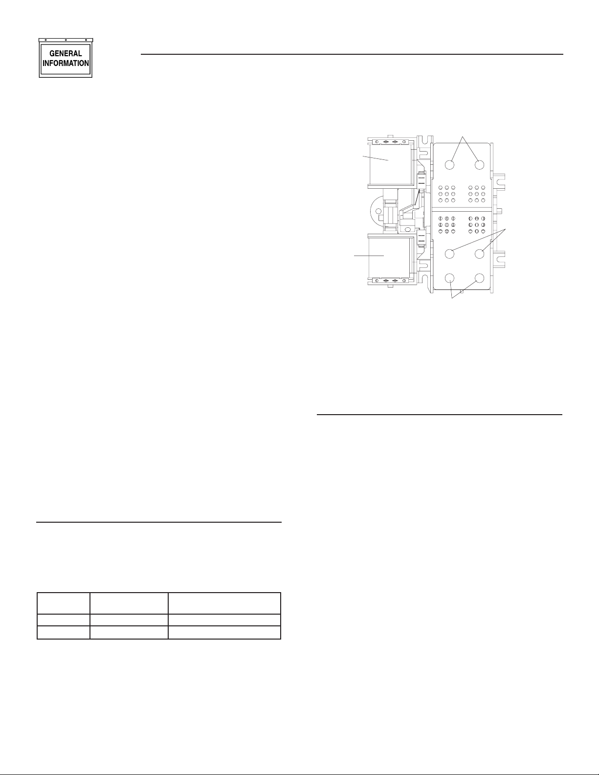
1.2.1 TRANSFER SWITCH MECHANISM
These switches (Figure 1.1) are used with a singlephase system, when the single-phase NEUTRAL line
is to be connected to a Neutral Lug and is not to be
switched.
Solderless, screw-type terminal lugs are standard.
Switch Wire Conductor Tightening
Rating Range Torque
100A #14-1/0 AWG 50 in-lbs.
200A #6-250 MCM 275 in-lbs.
This transfer switch is suitable for control of motors,
electric discharge lamps, tungsten filament and electric heating equipment where the sum of motor full
load ampere ratings and the ampere ratings of other
loads do not exceed the ampere rating of the switch
and the tungsten load does not exceed 30 percent of
the switch rating.
2
Figure 1.1 — Typical ATS Transfer Mechanism
UTILITY LUGS
UTILITY
CLOSING
COIL
GENERATOR
LUGS (E1 & E2)
GENERATOR
CLOSING
COIL
LOAD LUGS (T1 & T2)
This transfer switch is for use in optional standby
systems only.
This transfer switch is suitable for use on a circuit
capable of 10,000 rms symmetrical amperes, 240
VAC maximum.
1.2.2 SERVICE DISCONNECT CIRCUIT
BREAKER
The service disconnect circuit breaker for the 100
amp models are:
• Siemens, Type BQ, 2-pole
• 120/240VAC, 100A
• 50/60 Hertz
• Heating, Air Conditioning and Refrigeration (HACR)
rated
• Wire range: #1 - #8 AWG.
• The conductor tightening torque is 50 in-lbs.
The service disconnect circuit breaker for the 200
amp models are:
• Siemens, Type QN, 2-pole
• 120/240VAC, 200A
• 50/60 Hertz
• Heating, Air Conditioning and Refrigeration (HACR)
rated
• Wire range: 300 KCMIL - 4 AWG
• The conductor tightening torque is 250 in-lbs.
1.3 TRANSFER SWITCH DATA DECAL
A DATA DECAL is permanently affixed to the transfer
switch enclosure. Use this transfer switch only with
the specific limits shown on the DATA DECAL and
on other decals and labels that may be affixed to the
switch. This will prevent damage to equipment and
property.
Page 5

Section 2 — Installation
GTS “HS” Type Transfer Switch
When requesting information or ordering parts for this
equipment, make sure to include all information from
the DATA DECAL.
Record the Model and Serial numbers in the space
provided below for future reference.
MODEL #
SERIAL #
1.4 TRANSFER SWITCH ENCLOSURE
The standard switch enclosure is a National
Electrical Manufacturer’s Association (NEMA) 3R
type. NEMA 3R type enclosures primarily provide
a degree of protection against falling rain and sleet
and is undamaged by the formation of ice on the
enclosure.
1.5 SAFE USE OF TRANSFER SWITCH
Before installing, operating or servicing this equipment, read the SAFETY RULES (inside front cover)
carefully. Comply strictly with all SAFETY RULES to
prevent accidents and/or damage to the equipment.
The manufacturer recommends that a copy of the
SAFETY RULES are posted near the transfer switch.
Also, be sure to read all instructions and information
found on tags, labels and decals affixed to the equipment.
Two publications that outline the safe use of transfer
switches are the following:
• NFPA 70; National Electrical Code
• UL 1008, STANDARD FOR SAFETY-AUTOMATIC
TRANSFER SWITCHES
2.1 INTRODUCTION TO INSTALLATION
This equipment has been wired and tested at the
factory. Installing the switch includes the following
procedures:
• Mounting the enclosure.
• Connecting power source and load leads.
• Connecting the generator sensing and transfer
relay circuits.
• Connecting any auxiliary contact (if needed)
• Testing functions.
2.2 UNPACKING
Carefully unpack the transfer switch. Inspect closely
for any damage that might have occurred during shipment. The purchaser must file with the carrier any
claims for loss or damage incurred while in transit.
Check that all packing material is completely removed
from the switch prior to installation.
2.3 MOUNTING
Mounting dimensions for the transfer switch enclosure are in this manual. Enclosures are typically
wall-mounted. See “Installation Diagram”, Section 5.
Handle transfer switches carefully when install-
ing. Do not drop the switch. Protect the switch
against impact at all times, and against construction grit and metal chips. Never install a transfer
switch that has been damaged.
This transfer switch is mounted in a NEMA 3R enclosure. It can be mounted outside or inside and should
be based on the layout of installation, convenience
and proximity to the utility supply and load center.
Install the transfer switch as close as possible to the
electrical loads that are to be connected to it. Mount
the switch vertically to a rigid supporting structure.
To prevent switch distortion, level all mounting
points. If necessary, use washers behind mounting
holes to level the unit.
2.4 CONNECTING POWER SOURCE
AND LOAD LINES
DANGER
Make sure to turn OFF both the UTILITY
(NORMAL) and EMERGENCY ( STANDBY) power
supplies before trying to connect power source
and load lines to the transfer switch. Supply
voltages are extremely high and dangerous.
Contact with such high voltage power supply lines causes extremely hazardous, possibly
lethal, electrical shock.
Wiring diagrams and electrical schematics are provided in this manual.
Two suggested installation methods are shown. One
for new installations and/or retrofit and one for retrofit.
NOTE:
All installations must comply with national, state
and local codes. It is the responsibility of the
installer to perform an installation that will pass
the final electrical inspection.
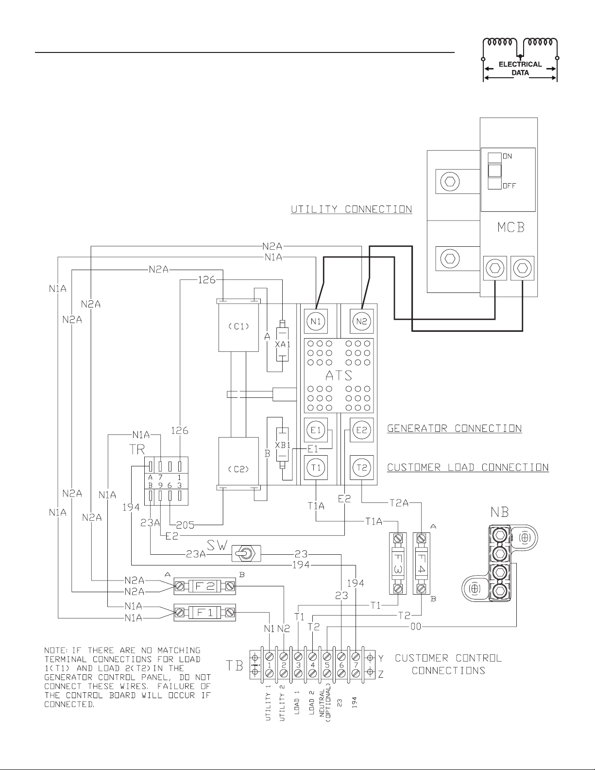
The utility supply connection is made at the circuit
breaker terminals. The generator supply and customer load connections are made at the transfer switch
mechanism, inside the switch enclosure.
3
Page 6
Section 3 — Operation
ATS “HS” Type Transfer Switch
Conductor sizes must be adequate to handle the
maximum current to which they will be subjected to,
based on the 75°C column of tables, charts, etc. used
to size conductors. The installation must comply fully
with all applicable codes, standards and regulations.
Before connecting wiring cables to terminals, remove
any surface oxides from the cable ends with a wire
brush. All power cables must enter the enclosure
through the knockouts. If not using the knockouts,
entry must be at or below knockouts. If ALUMINUM
conductors are used, apply corrosion inhibitor to
conductors. Tighten terminal lugs to the torque
values as noted in Section 1.2.2, and on the decal
located on the inside of the door. After tightening terminal lugs, carefully wipe away any excess corrosion
inhibitor.
Use a torque wrench to tighten the conduc-
tors, being sure not to overtighten, or damage
to the switch base could occur. If not tightened
enough, a loose connection would result, causing excess heat which could damage the switch
base.
Connect power source load conductors to clearly
marked transfer mechanism terminal lugs as follows
1. Connect UTILITY (NORMAL) power source cables
to circuit breaker.
2. Connect EMERGENCY (STANDBY) source power
cables to transfer switch terminals E1, E2.
3. Connect customer LOAD leads to switch terminals T1, T2.
Conductors must be properly supported, of approved
insulative qualities, protected by approved conduit,
and of the correct wire gauge size in accordance with
applicable codes.
Be sure to maintain proper electrical clearance
between live metal parts and grounded metal. Allow
at least 1/2 inch for 100-400 amp circuits.
2.5 CONNECTING START CIRCUIT
WIRES
Control system interconnections consist of N1 and
N2, T1 and T2, and leads 23 and 194. Control system
interconnection leads must be run in a conduit that
is separate from the AC power lead. Recommended
wire gauge sizes for this wiring depends on the length
of the wire, as recommended below:
MAXIMUM WIRE LENGTH RECOMMENDED WIRE
SIZE
460 feet (140m) No. 18 AWG.
461 to 730 feet (223m) No. 16 AWG.
731 to 1,160 feet (354m) No. 14 AWG.
1,160 to 1,850 feet (565m) No. 12 AWG.
4
NOTE:
When this ATS is used with an air-cooled generator, the LOAD 1 and LOAD 2 wires are not used.
3.1 FUNCTIONAL TESTS AND
ADJUSTMENTS
Following transfer switch installation and interconnection, inspect the entire installation carefully. A competent, qualified electrician should
inspect it. The installation should comply strictly
with all applicable codes, standards, and regulations. When absolutely certain the installation is
proper and correct, complete a functional test of
the system.
Perform functional tests in the exact order pre-
sented in this manual, or damage could be done
to the switch.
IMPORTANT: Before proceeding with functional tests,
read and make sure all instructions and information
in this section are understood. Also read the information and instructions of labels and decals affixed
to the switch. Note any options or accessories that
might be installed and review their operation.
3.2 MANUAL OPERATION
DANGER
Do NOT manually transfer under load.
Disconnect transfer switch from all power sources by approved means, such as the main circuit
breaker(s).
A manual HANDLE is shipped with the transfer
switch. Manual operation must be checked BEFORE
the transfer switch is operated electrically. To check
manual operation, proceed as follows:
1. Turn the generator’s AUTO/OFF/MANUAL switch
to OFF.
2. Turn OFF both UTILITY (service disconnect cir-
cuit breaker) and EMERGENCY (generator main
line to circuit breaker) power supplies to the
transfer switch.
3. Turn the GENERATOR DISCONNECT SWITCH
to the OFF position.
4. Note position of transfer mechanism main con-
tacts by observing the moveable contact carrier
arm. This can be viewed through the long narrow
slot in the inside cover of the ATS. The top of the
moveable contact carrier arm is yellow to be easily identified.
• Manual operation handle in the UP position LOAD terminals (T1, T2) are connected to UTILITY terminals (N1, N2).
Page 7

Figure 3.1 — Actuating Transfer Switch
Attach handle to
the moveable contact
carrier arm.
Move handle UP for the
NORMAL (UTILITY) position.
Section 3 — Operation
ATS “HS” Type Transfer Switch
NOTE: Return handle to
storage position in enclosure
when finished with manual transfer.
Move handle DOWN for the
STANDBY (EMERGENCY)
position.
• Manual operation handle in the DOWN position - LOAD terminals (T1, T2) are connected to
EMERGENCY terminals (E1, E2).
Do not use excessive force when operating the
transfer switch manually or damage could be
done to the manual handle.
3.2.1 CLOSE TO NORMAL SOURCE SIDE
Before proceeding, verify the position of the switch by
observing the position of manual operation handle in
Figure 3.1. If the handle is UP, the contacts are closed
in the NORMAL (UTILITY) position, no further action
is required. If the handle is DOWN, proceed with Step
1.
Step 1: With the handle inserted into the moveable
contact carrier arm, move handle UP. Be
sure to hold on to the handle as it will move
quickly after the center of travel.
Step 2: Remove manual operating handle from move-
able contact carrier arm. Return handle to
storage bracket.
3.2.2 CLOSE TO EMERGENCY SOURCE SIDE
Before proceeding, verify the position of the switch
by observing the position of the manual operation
handle in Figure 3.1. If the handle is DOWN, the
contacts are closed in the EMERGENCY (STANDBY)
position. No further action is required. If the handle
is UP, proceed with Step 1.
Step 1: With the handle inserted into the moveable
contact carrier arm, move the handle DOWN.
Be sure to hold on to the handle as it will
move quickly after the center of travel.
Step 2: Remove manual operating handle from move-
able contact carrier arm. Return handle to
storage bracket.
3.2.3 RETURN TO NORMAL SOURCE SIDE
Step 1: Manually actuate switch to return manual
operating handle to the UP position.
Step 2: Remove manual operating handle from move-
able contact carrier arm. Return handle to
storage bracket.
5
Page 8

Section 3 — Operation
ATS “HS” Type Transfer Switch
3.3 VOLTAGE CHECKS
1. Turn ON the UTILITY power supply to the transfer switch using the service disconnect circuit
breaker.
DANGER
PROCEED WITH CAUTION. THE TRANSFER
SWITCH IS NOW ELECTRICALLY HOT. CONTACT
WITH LIVE TERMINALS RESULTS IN EXTREMELY
HAZARDOUS AND POSSIBLY FATAL ELECTRICAL
SHOCK.
2. With an accurate AC voltmeter, check for correct
voltage. Measure across ATS terminal lugs N1
and N2. Also check N1 to NEUTRAL and N2 to
NEUTRAL.
3. When certain that UTILITY supply voltage is correct and compatible with transfer switch ratings,
turn OFF the UTILITY supply to the transfer
switch.
4. On the generator panel, set the AUTO/OFF/
MANUAL switch to MANUAL position. The generator should crank and start.
5. Let the generator stabilize and warm up at noload for at least five minutes.
6. Turn the GENERATOR DISCONNECT SWITCH
to the ON position.
7. Set the generator's main circuit breaker (CB1) to
its ON or CLOSED position.
DANGER
PROCEED WITH CAUTION. GENERATOR
OUTPUT VOLTAGE IS NOW BEING DELIVERED
TO TRANSFER SWITCH TERMINALS. CONTACT
WITH LIVE TERMINALS RESULTS IN EXTREMELY
DANGEROUS AND POSSIBLY FATAL ELECTRICAL
SHOCK.
8. With an accurate AC voltmeter and frequency
meter, check the no-load, voltage and frequency.
Measure across ATS terminal lugs E1 to E2. Also
check E1 to NEUTRAL and E2 to NEUTRAL.
a. Frequency ....................................... 60-62 Hertz
b. Terminals E1 to E2 ........................ 240-246 VAC
c. Terminals E1 to NEUTRAL ............. 120-123 VAC
d. Terminals E2 to NEUTRAL ............. 120-123 VAC
9. Set the generator’s main circuit breaker (CB1) to
its OFF or OPEN position.
10. Set the AUTO/OFF/MANUAL switch to the
OFF position to shut down the generator.
NOTE:
Do NOT proceed until generator AC output voltage and frequency are correct and within stated
limits. If the no-load voltage is correct but no-load
frequency is incorrect, the engine governed speed
may require adjustment. If no-load frequency is
correct but voltage is not, the voltage regulator
may require adjustment.
3.4 GENERATOR TESTS UNDER LOAD
1. Set the generator's main circuit breaker to its
OFF or OPEN position.
2. Manually actuate the transfer switch main contacts to their EMERGENCY (STANDBY) position.
Refer to Manual Operation (Section 3.2).
3. To start the generator, set the AUTO/OFF/ MANUAL
switch to MANUAL. When engine starts, let it stabilize for a few minutes.
4. Turn the generator's main circuit breaker to its
ON or CLOSED position. The generator now powers all LOAD circuits. Check generator operation
under load as follows:
• Turn ON electrical loads to the full rated wattage/amperage capacity of the generator. DO
NOT OVERLOAD.
• With maximum rated load applied, check
voltage and frequency across transfer switch
terminals E1 and E2. Voltage should be
greater than 230VAC and frequency should be
greater than 59 Hertz.
• Let the generator run under rated load for at
least 30 minutes. With unit running, listen for
unusual noises, vibration, overheating, etc.,
that might indicate a problem.
5. When checkout under load is complete, set main
circuit breaker of the generator to its OFF or
OPEN position.
6. Let the generator run at no-load for several
minutes. Then, shut down by setting the AUTO/
OFF/MANUAL switch to its OFF position.
7. Move the switch's main contacts back to their
UTILITY position. For example, LOAD connected to UTILITY power supply. Refer to Manual
Operation (Section 3.2). Handle and operating
lever of transfer switch should be in UP position.
8. Turn on the utility power supply to transfer
switch, using whatever means provided (such
as a utility main line circuit breaker). The utility
power source now powers the loads.
9. Set the generator's AUTO/OFF/MANUAL switch to
its AUTO position.
10. Set the GENERATOR DISCONNECT SWITCH to
the ON position. The system is now set for fully
automatic operation.
6
Page 9

]
]
]
OR
E
3
S
]
0A6599tv
"
]
E
E
E
E
S
]
OCK
)
ON
0A6599tv
]
Section 4 — Installation Diagram
ATS “HS” Type Transfer Switch
Drawing No. 0F0016-B
597mm[23.50"
271mm[10.67"
MOUNTING HOLE
6.3mm[0.25"
26.5mm[1.04"
561mm[22.09
PADL
CUSTOMER SUPPLIED
LOCATI
34mm[1.34"
179.5mm[7.07"
KNOCKOUT SUITABL
FOR 3/4" & 1" CONDUIT SIZ
KNOCKOUT SUITABLE F
1", 1-1/4", 1-1/2" CONDUIT SIZ
PLACE
KNOCKOUT SUITABL
FOR 1", 1-1/4", 1-1/2" CONDUIT SIZ
324mm[12.76"
7
Page 10

Section 5 — Electrical Data
G
O
O
O
O
COO
U
S
S
O
SCO
C
C
O
O
O
S
O
U
OU
G
Y
O
O
O
OU
C
C
CO
S
,
C
S
C
C
US
S
O
O
O
C
SCO
C
S
S
US
S
S
C
C
C
O
G
JU
S
S
O
O
OC
CO
S
S
ATS “HS” Type Transfer Switch
Transfer Switch Interconnections - Drawing No. 0F0017-A
E
MEET
.
E ENTRAN
DE
MPER WILL NEED
ERVI
IZED T
AL
NDIN
ED A
TALLED
I
NAL & L
E A B
BE IN
ATI
EVI
F AT
T
NNE
E DI
ERVI
T
.
NE BY A
DE
STATE AND
IAN AND M
BE D
AL
TRI
N T
TRI
ED ELE
AL ELE
EN
TALLATI
EET ALL NATIONAL
I
T
NNE
NDIN
I
ND BAR
R
ARD
N
TI
NNE
N PANELB
TRAL BAR
E
N
FIT
TALLATI
R RETR
EW IN
TE: IN
ARD
ANELB
NIT
LED
R
R
M
LTERNAT
TAT
R
T
T
N AIR
T1 & T2 N
ED
ND SOME LIQUID COOLED UNITS
-WIRE
4
R
L PANEL
ND BAR
R
ENERAT
NTR
KET
TILIT
8
Page 11

L
R
R
D
SCO
CT
ON
G
D
OT
COO
S
T
CE
D
T
S.
O
D
)
G
OR
E
&
).
TILIT
Y
T
UST
OR
OR
OM
33
OC
S.
D
SCO
CT
S
S
KE
Section 5 — Electrical Data
ATS “HS” Type Transfer Switch
Transfer Switch Interconnections - Drawing No. 0F0017-A
IF ATS IS USED AS SERVICE ENTRAN
DEVICE A BONDING JUMPER WILL NEE
TO BE INSTALLED SIZED TO MEE
ATIONAL & LOCAL CODE
EXISTING WIRES T
PANELBOAR
SEE ABOVE NOTE
INSULATED SPLICIN
NNECTOR
NEW WIRES CAN B
PULLED FROM ATS
PANELBOARD
ERVICE DI
NNE
AT
NOTE: INSTALLATION TO BE DONE BY A
LICENSED ELECTRICIAN AND M
MEET ALL NATIONAL, STATE AN
L
AL ELECTRICAL CODE
FR
ALTERNAT
TAT
*-WIRES T1 & T2 N
DI
NNE
BONDIN
NNECTI
IN PANELBOAR
NEUTRAL BA
ROUND BA
PANELBOAR
AC GENERATOR
NTROL PANE
ED ON AIR
AND SOME LIQUID COOLED UNIT
LED UNIT
RETROFI
9
Page 12

Section 5 — Electrical Data
ATS “HS” Type Transfer Switch
Wiring Diagram/Schematic - Drawing No. 0F0015-A
10
Page 13
Section 5 — Electrical Data
ATS “HS” Type Transfer Switch
Wiring Diagram/Schematic - Drawing No. 0F0015-A
11
Page 14

Section 6 — Exploded Views and Parts List
ATS “HS” Type Transfer Switch
100A Transfer Switch Assembly – Drawing No. 0F0466$-D
46
44
DETAIL A-A
(POWER TERMINAL LUG ASSY)
TIGHTEN ITEM #43: 24-30 IN/LBS
NOTE:
43
44
43
DETAIL B-B
(POWER TERMINAL LUG ASSY)
TIGHTEN ITEM #43: 24-30 IN/LBS
46
NOTE:
33
3
2
15
16
6
TERMINAL TIGHTENING
TORQUE 50 INCH-POUNDS
!
32
4
10
31
47
48
TERM. XA1
TERM. XA2
TERMINAL TIGHTENING
TORQUE 50 INCH-POUNDS
SWITCH XA
TERM. XA3
SWITCH LEVER
SWITCH LEVER
TERM. XB1
SWITCH XB
TERM. XB3
51
54
NOTE:
TERM. XB2
ASSEMBLE SENSING WIRE
CLEARANCE IS GIVEN FOR
RING TERMINALS SO
5
ACCESS TO LOWER LUG
SCREWS.
!
0A6599tv
0A6599tv0A6599tv
63378-T
0A9457
63378-T
A
A
63378-T
A
30A, 600V
D2806-T
63378-T
0D3587
Replace with UL
listed fuse of same
600 Volt, 5 amp.
type and rating
63378-T63378-T
LISTED
US
64NL
63378-T
B
B
E1
B
D2806-T
30A, 600V
R
STAND-BY SYSTEMS
FOR USE IN OPTIONAL
C
AUTOMATIC TRANSFER SWITCH
63378-T
194WIRE
23WIRE
T2
T1
N2WIRE
N1
47822-T
38
30
378 37
QTY. 1 ITEM #37 ABOVE SUBPLATE
QTY. 2 ITEM #37's BELOW SUBPLATE
4 PLACES
0A6599tv
19
7
24
P/N 0A2595
NOTE WIRE ORIENTATION
WARNING
(12 VDC)
(12 VDC)
(OPTIONAL)
NEUTRAL
(240 VAC)
WIRE
(240 VAC)
WIRE
(240 VAC)
CUSTOMER CONNECTIONS
(240 VAC)
WIRE
DECAL DETAILS
(NOT TO SCALE)
VIEWS SHOWN WITH ITEMS #18 & #19 FULLY ASSEMBLED
20
0E9999
0E3485
OF
29
COVER
INSIDE
0E3484
18
0C8308
49 45
23
41 4240
28
0A6599tv0A6599tv
0A6599tv
0A6599tv
VIEW SHOWN WITH ITEMS #18 & #19 REMOVED
17
INSIDE RIGHT SIDE
50
OR ALUUMINUM WIRE OF AT LEAST 75° c RATING
ALL TERMINALS LUGS ARE SUITABLE FOR COPPER
#0C1026 OR #0D8440 0R #0E0117 OR #0E5241A
SWITCH IS FOR USE WITH CONTROL PANEL ASSEMBLY
RATING
SWITCH
INSIDE LEFT SIDE
22
WAUKESHA, WI.
GENERAC POWER SYSTEMS, INC.
MAXIMUM VOLTS - 240
MAXIMUM AMPS - 100
TRANSFER SYSTEM DATA
1/4 STL
22097-S
22473-S
1-4X20STL
22473-S
1-4X20STL
!
13
26
27
52
53
1211 31
19
0F2710
MODEL NUMBER
SERIAL NUMBER
SYSTEM VOLTAGE
0C4449A-RS
18
D2806-E
30A, 600V
1
1211 31
21
30A, 600V
D2806-S
48850-E
14
TERMINAL TIGHTENING
TORQUE 45 INCH-POUNDS
B
35
8
36
1/4 STL
22097-S
22473-S
1-4X20STL
22473-S
1-4X20STL
934
DETAIL "A"
9
34
35
DETAIL A
(GROUND LUG ASSEMBLY)
ENCLOSURE
12
Page 15

Section 6 — Exploded Views and Parts List
ATS “HS” Type Transfer Switch
100A Transfer Switch Assembly – Drawing No. 0F0466$-D
ITEM PART NO. QTY. DESCRIPTION
1 0C2237 1 TRANSFER SW- HSB 100A 2P 250V
2 0E7886H 1 CB 0100A 2P 240V S BQ2 LB
3 0E7890 1 BRKT CB MTG BACK
4 0E9906 1 BRACKET, DISCONNECT SWITCH 100A
5 063378 8 HOLDER, CABLE TIE
6 0D3728 1 SWITCH TOG SPST 15A @ 125V
7 0E9999 1 DECAL SERVICE DISCONNECT SWITCH
8 049813 4 NUT HEX M6 X 1.0 G8 YEL CHR
9 0E6523 1 GROUND BAR (5)4-14 AWG CONN
10 *** 063617 1 RELAY PNL 12VDC DPDT 10A@240VA
11 *** 0D2806 2 FUSEBLOCK 30A 600V 2POS W/SQ
12 073590A 4 FUSE 5A X BUSS
1 3 *** 047822 1 BLOCK TERM 20A 7 X 6 X 1100V
14 0A1661 2 RIVET POP .156 X .675 AL
15 0C4449 1 ASS’Y-NTRL BL 150-200A
16 090388 2 SCREW HHTT M6-1.0 X 12 ZINC
17 0E1473 1 WELDMENT TRANSFER SWITCH BOX
18 0E9907 1 COVER INSIDE XFER SWITCH BOX
19 0E1477 1 COVER TRANSFER SWITCH BOX
20 0F0668 1 DECALTRANSFER SWITCH
21 0E3070 1 SUBPLT XFER SW HSB
22 0E9734 REF DECAL SWITCH RATING
23 0E3484 1 DECAL WARN MANUAL OPER HANDLE
24 0E3485 1 DECAL SERVICE DISCONNECT
25 067210A 1 DECAL GROUND LUG (NOT SHOWN)
26 0A9457 1 DECAL NEUTRAL
27 0D3587 1 DECAL FUSE REPLACEMENT
28 0A2595 1 DECAL TERMINAL STRIP
29 0F0776 1 DECAL TEST SEQ. 2P TS HS 3R
30 081221 1 DECAL-UL LIST HSB
31 045764 6 SCREW HHTT M4-0.7 X 8 BP
32 074908 2 SCREW HHTT M5-0.8 X 10 BP
33 066849
34 0C3992 2 SCREW HHTT M4-0.7 X 16 BP
35 026579 2 WASHER SHAKEPROOF EXT #8 STEEL
36 0E7213 2 SCREW THUMB 1/4-20 X 1/2 W/SHLD
37 022473 8 WASHER FLAT 1/4-M6 ZINC
38 022097 4 WASHER LOCK M6-1/4
39 0E9987 1 WIRE HARNESS HSB (NOT SHOWN)
40 0E6193 1 BRACKET ARM EXTENDER
41 064526 2 SCREW HWHS #6-25 X 3/8 ZNC
42 ** 0E6155 1 ARM EXTENDER PIN
43 036933 6 SCREW PPHM #10-32 X 3/8
44 077033 6 LUG SLDLSS 1/0-#14X9/16 AL/CU
45 0C8308 1 DECAL TERMINAL SHOCK HAZARD
46 022152 6 WASHER LOCK #10
47 0912
48 0912970086 1 WIRE ASSY 2AWG 100A 2-P T/S N2A
49 095282 1 DECAL LIVE-CIRCUIT
50 0F2710 1 DECAL XFER SWITCH DATA SE 100A
51 066849 4 SCREW HHTT M5-0.8 X 16
52 0E6303 1 WIRE – A
53 0E6303A 1 WIRE – B
54 0E6303C 1 WIRE – E1
B 2 SCREW HHTT M5-0.8 X 8 BP
970085 1 WIRE ASSY 2AWG 100A 2-P T/S N1A
*** SUPPLIED WITH WIRE HARNESS ITEM #39
** SUPPLIED WITH TRANSFER SWITCH (ITEM #1)
13
Page 16
Section 6 — Exploded Views and Parts List
ATS “HS” Type Transfer Switch
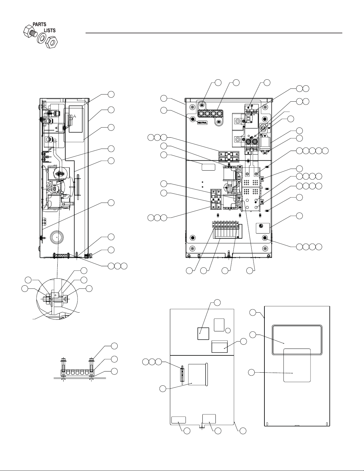
200A Transfer Switch Assembly – Drawing No. 0E9801$-F
38
8
SWITCH
22097-S
1/4 STL
22473-S
22473-S
1-4X20STL
1-4X20STL
0C4449A-RS
30A, 600V
D2806-E
22097-S
1/4 STL
22473-S
1-4X20STL
D2806-S
30A, 600V
48850-E
22097-S
1/4 STL
22473-S
22473-S
1-4X20STL
1-4X20STL
22097-S
1/4 STL
22473-S
1-4X20STL
BUSBAR HARDWARE
DETAIL
ENCLOSURE
RATING
SWITCH
SWITCH IS FOR USE WITH CONTROL PANEL ASSEMBLY
#0C1026 OR #0D8440 0R #0E0117 OR #0E5241A
MAXIMUM AMPS - 200
MAXIMUM VOLTS - 240
TRANSFER SYSTEM DATA
120/240
SYSTEM VOLTAGE
MODEL NUMBER
SERIAL NUMBER
DETAIL A
(GROUND LUG ASSEMBLY)
ALL TERMINALS LUGS ARE SUITABLE FOR COPPER
OR ALUUMINUM WIRE OF AT LEAST 75° c RATING
0F2712
BUSBAR
16
INSIDE RIGHT SIDE
55
19
GENERAC POWER SYSTEMS, INC.
WAUKESHA, WI.
INSIDE LEFT SIDE
22
17
26
0A6599tv0A6599tv0A6599tv
0A9457
3111 12
4
46
27
18
Replace with UL
listed fuse of same
type and rating
600 Volt, 5 amp.
0D3587
47
15
0C4449A-T
31
3
2
53
52
NOTE:LOCATE HOLE IN BUSBAR
UNDER BALL END OF SCREW
0A6599tv0A6599tv0A6599tv
TIGHTENING TORQUE 250 IN-LBS
33
31
UTILITY
(C1 & VR1)
71037 388
D2806-T
30A, 600V
63378-T
AA
63378-T
63378-T
SEE SIDE VIEW FOR HARDWARE DETAIL
TORQUE ITEM #8 TO 12 FT-LBS
56
53038
63378-T
5
386645
43
44
TORQUE ITEM #6
TO 72 IN-LBS.
1
STANDBY
D2806-T
30A, 600V
21
(C2 & VR2)
63378-T
11 3112
47822-T
T2
T1N2N1
(240 VAC)
(240 VAC)
(240 VAC)
WIRE
WIRE
WIRE
WIRE
32
0A6599tv0A6599tv0A6599tv
CUSTOMER CONNECTIONS
36
43
DETAIL "A"
35349
13
28 14
E1E1
BB
63378-T
194
23
(12 VDC)
(12 VDC)
(240 VAC)
NEUTRAL
WIRE
WIRE
(OPTIONAL)
WARNING
P/N 0A2595
NOTE WIRE ORIENTATION
R
C
AUTOMATIC TRANSFER SWITCH
FOR USE IN OPTIONAL
STAND-BY SYSTEMS
63378-T
63378-T
LISTED
US
64NL
0A6599tv0A6599tv0A6599tv
0A6599tv
50
32 3737 38
QTY. 2 ITEM #37's BELOW SUBPLATE
QTY. 1 ITEM #37 ABOVE SUBPLATE
4 PLACES
48
37
7
DECAL DETAILS
VIEWS SHOWN WITH ITEMS #18 & #19 FULLY ASSEMBLED
(NOT TO SCALE)
24
19
0E3485
34
0E9999
9
40 4241
35
0E3484
20
51
29
INSIDE
OF
COVER
AUTOMATIC
TRANSFER SWITCH
NEMA 3R - INDOOR/OUTDOOR USE
23
14
0C8308
54 49
18
Page 17

Section 6 — Exploded Views and Parts List
ATS “HS” Type Transfer Switch
200A Transfer Switch Assembly – Drawing No. 0E9801$-F
ITEM PART NO. QTY. DESCRIPTION
1 0D9618 1 TRANSFER SW- HSB 200A 2P 250V
2 0E3628 1 CIRCUIT BREAKER 0200A 2P 120/240V S QN
3 0E3664 1 BASE QN CIRCUIT BREAKER
4 0E3553 2 BUSBAR 200A HSB XFER SW
5 0E3375 4 LUG SLDLSS 250-#6 AL/CU
6 0F1252 4 SCREW BHSC 1/4-20 X 3/8
7 036656 2 SCREW SHC 1/4-20 X 1 G8.8 NZ
8 022127 2 NUT HEX 1/4-20 STEEL
9 0E6523 1 GROUND BAR (5)4-14 AWG CONN
10 063617 1 RELAY PNL 12VDC DPDT 10A@240VA
11 0D2806 2 FUSEBLOCK 30A 600V 2POS W/SQ
12 073590A 4 FUSE 5A X BUSS
13 047822 1 BLOCK TERM 20A 7 X 6 X 1100V
14 0A1661 2 RIVET POP .156 X .675 AL
15 0C4449A 1 ASS’Y-NTRL BL150-200A
16 090388 2 SCREW HHTT M6-1.0 X 12 ZINC
17 0E1473 1 WELDMENT TRANSFER
18 0E9989 1 COVER INSIDE XFER SWITCH BOX
19 0E1477 1 COVER TRANSFER SWITCH BOX
20 0F0668 1 DECALTRANSFER SWITCH
21 0E3070 1 SUBPLT XFER SW HSB
22 0E3477 REF DECAL SWITCH RATING
23 0E3484 1 DECAL WARN MANUAL OPER HANDLE
24 0E3485 1 DECAL SERVICE DISCONNECT
25 067210A 1 DECAL GROUND LUG (NOT SHOWN)
26 0A9457 1 DECAL NEUTRAL
27 0D3587 1 DECAL FUSE REPLACEMENT
28 0A2595 1 DECAL TERMINAL STRIP
29 0E7109 1 DECAL TEST SEQ.2P TS HS 3R
30 063378 8 HOLDER CABLE TIE
31 045764 8 SCREW HHTT M4-0.7 X 8 BP
32 049813 5 NUT HEX M6 X 1.0 G8 YEL CHR
33 0749
34 0C3992 2 SCREW HHTT M4-0.7 X 16 BP
35 026579 2 WASHER SHAKEPROOF EXT #8 STEEL
36 0E7213 2 SCREW THUMB 1/4-20 X 1/2 W/SHLD
37 022473 14 WASHER FLAT 1/4-M6 ZINC
38 022097 10 WASHER LOCK M6-1/4
39 0E9987 1 WIRE HARNESS HSB (NOT SHOWN)
40 0E6193 1 BRACKET ARM EXTENDER
41 064526 2 SCREW HWHS #6-25 X 3/8
42 * 0E6155 1 ARM EXTENDER PIN
43 * 0E6032 2 90 DEGREE UP SPADE CONNECTOR
44 * 0E6033 2 90 DEGREE DN SPADE CONNECTOR
45 * 0E6034 2 STRAIGHT SPADE CONNECTOR
46 0E6303
47 0E6303A 1 WIRE B
48 0E6303B 1 WIRE E1
49 0C8308 1 DECAL TERMINAL SHOCK HAZARD
50 081221 1 DECAL-UL LIST HSB
51 0E9999 1 DECAL-SERVICE DISCONNECT SWITCH
52 0E9988 1 BRACKET SERVICE SWITCH
53 0D3728 1 TOBBLE SWITCH, SERVICE
54 095282 1 DECAL LIVE-CIRCUIT
55 0F2712 1 DECAL XFER SWITCH DATA SE 200A
56 066849 5 SCREW HHTT M5-0.8 X 16
08 2 SCREW HHTT M5-0.8 X 10 BP
1 WIRE A
SWITCH BOX
* SUPPLIED WITH TRANSFER SWITCH ITEM #1
15
Page 18

Section 7 — Notes
ATS “HS” Type Transfer Switch
16 Generac® Power Systems, Inc.
Page 19

Section 7 — Notes
ATS “HS” Type Transfer Switch
Generac® Power Systems, Inc. 17
Page 20

Section 8 — Warranty
ATS “HS” Type Transfer Switch
GENERAC POWER SYSTEMS, INC. WARRANTY/SERVICE
Generac Power Systems, Inc. will warrant that from the date of purchase, our transfer
switch will be free from defects in material and workmanship for the items and periods set
forth in the warranty statement found in the owners manual of the Generac Power Systems
Inc. generator that this transfer switch will be utilized with.
Any equipment that the purchaser/owner claims to be defective must be examined by the
nearest Generac Authorized Warranty Service Dealer by visiting our website at www.generac.com or by calling the dealer locator number at 1-800-333-1322. Select the prompt that
describes the brand name of the generator.
THIS WARRANTY IS IN PLACE OF ALL OTHER WARRANTIES, EXPRESSED OR
IMPLIED, SPECIFICALLY, GENERAC MAKES NO OTHER WARRANTIES AS TO THE
MERCHANTABILITY OR FITNESS FOR A PARTICULAR PURPOSE.
Some states do not allow limitations on how long an implied warranty lasts, so the above
limitation may not apply to you.
GENERAC’S ONLY LIABILITY SHALL BE THE REPAIR OR REPLACEMENT OF PART(S)
AS STATED ABOVE. IN NO EVENT SHALL GENERAC POWER SYSTEMS, INC. BE
LIABLE FOR ANY INCIDENTAL, OR CONSEQUENTIAL DAMAGES, EVEN IF SUCH
DAMAGES ARE A DIRECT RESULT OF GENERAC’S NEGLIGENCE.
Some states do not allow the exclusion or limitation of incidental or consequential dam-
ages, so the above limitations may not apply to you.
This warranty gives you specific legal rights. You also may have other rights that vary from
state to state.
GENERAC® POWER SYSTEMS, INC.
P.O. BOX 297 • WHITEWATER, WI 53190
Part No. 0E9905 Revision F (07/21/05) Printed in U.S.A.
 Loading...