

Page 1
POWER SYSTEMS, INC.
®
Owner’s Manual
GTS “W” Type
Automatic
Transfer Switch
200 Amp, 250 Volts
Model Nos. 004635-1
004635-2
This manual should remain with the unit.
Page 2
Generac®Power Systems, Inc.
Generac cannot possibly anticipate every possible
circumstance that might involve a hazard. The warnings in this manual, and on tags and decals
affixed to the unit are, therefore, not all-inclusive. If
you use a procedure, work method or operating technique Generac does not specifically recommend, satisfy yourself that it is safe for you and others. Also
must make sure the procedure, work method or
operating technique that is used does not render the
transfer switch unsafe.
Throughout this publication, and on tags and
decals affixed to the generator, DANGER, WARNING,
CAUTION and NOTE blocks are used to alert personnel to special instruction about a particular operation that may be hazardous if performed incorrectly
or carelessly. Observe them carefully. The definitions
are as follows:
After this heading, read instructions that, if not
strictly complied with, will result in personal injury
or property damage.
After this heading, read instructions that, if not
strictly complied with, may result in personal injury
or property damage.
After this heading, read instructions that, if not
strictly complied with, could result in damage to
equipment and/or property.
NOTE:
After this heading, read explanatory statements
that require special emphasis.
These safety warnings cannot eliminate the hazards
that they indicate. Common sense and strict compliance with the special instructions while performing the
service are essential to preventing accidents.
Four commonly used safety symbols accompany the
DANGER, WARNING and CAUTION blocks. The type
of information each indicates follows:
This symbol points out important safety information that, if not followed, could endanger personal
safety and/or property of others.
This symbol points out potential explosion hazard.
This symbol points out potential fire hazard.
This symbol points out potential electrical shock
hazard.
GENERAL HAZARDS
• Any AC generator that is used for backup power if
a NORMAL (utility) power source failure occurs,
must be isolated from the NORMAL (utility) power
source by means of an approved transfer switch.
Failure to properly isolate the NORMAL and
STANDBY power sources from each other may
result in injury or death to electric utility workers,
due to backfeed of electrical energy.
• Improper or unauthorized installation, operation,
service or repair of the equipment is extremely
dangerous and may result in death, serious personal injury, or damage to equipment and/or personal property.
• Extremely high and dangerous power voltages are
present inside an installed transfer switch. Any
contact with high voltage terminals, contacts or
wires will result in extremely hazardous, and possibly LETHAL, electric shock. DO NOT WORK ON
THE TRANSFER SWITCH UNTIL ALL POWER
VOLTAGE SUPPLIES TO THE SWITCH HAVE
BEEN POSITIVELY TURNED OFF.
• Competent, qualified personnel should install,
operate and service this equipment. Adhere strictly to local, state and national electrical and building codes. When using this equipment, comply
with regulations the National Electrical Code
(NEC), CSA Standard; C22.1 Canadian Electric
Code and Occupational Safety and Health
Administration (OSHA) have established.
• Never handle any kind of electrical device while
standing in water, while barefoot, or while hands
or feet are wet. DANGEROUS ELECTRICAL
SHOCK MAY RESULT.
!
!
Important Safety Instructions
Read the following information carefully before attempting to install, operate or service this
equipment. Also read the instructions and information on tags, decals, and labels that may
be affixed to the transfer switch. Replace any decal or label that is no longer legible.
DANGER! Connection of a generator to an electrical system normally supplied by an electric
utility shall be by means of suitable transfer equipment so as to isolate the electric system
from utility distribution system when the generator is operating (Article 701 Legally Required
Standby Systems or Article 702 Optional Standby Systems, as applicable). Failure to isolate
electric system by these means may result in damage to generator and may result in injury
or death to utility workers due to backfeed of electrical energy.
!
!
!
!
DANGER
!
Page 3

Table of Contents
Generac®Power Systems, Inc. 1
Safety Rules..........................................Inside Front Cover
Section 1 — General Information ..................................2
1.1 Introduction ............................................................2
1.2 Equipment Description ............................................2
1.3 Transfer Switch Data Decal......................................2
1.4 Transfer Switch Enclosure ......................................2
1.5 Safe Use Of Transfer Switch ....................................2
Section 2 — Installation ....................................................3
2.1 Introduction to Installation ......................................3
2.2 Unpacking ................................................................3
2.3 Mounting ..................................................................3
2.4 Connecting Power Source and Load Lines................3
2.4.1 2-Pole Mechanism ..........................................3
2.4.2 3-Pole Mechanism ..........................................3
2.5 Connecting Start Circuit Wires ................................4
2.6 Auxiliary Contacts ....................................................4
Section 3 — Operation ......................................................5
3.1 Functional Tests & Adjustments ..............................5
3.2 Manual Operation ....................................................5
3.2.1 Close to Normal Source Side ........................5
3.2.2 Close to Emergency Source Side....................5
3.2.3 Return to Normal Source Side ......................5
3.3 Voltage Checks..........................................................5
3.4 Generator Tests Under Load ....................................7
Section 4 – Mounting Dimensions ................................8
Section 5 – Electrical Data ..............................................9
Section 6 – Exploded Views & Parts Lists ..................14
Section 7 – Warranty ......................................Back Cover
• Because jewelry conducts electricity, wearing it
may cause dangerous electrical shock. Remove all
jewelry (such as rings, watches, bracelets, etc.)
before working on this equipment.
• If work must be done on this equipment while
standing on metal or concrete, place insulative
mats over a dry wood platform. Work on this
equipment only while standing on such insulative
mats.
• Never work on this equipment while physically or
mentally fatigued.
• Keep the transfer switch enclosure door closed and
bolted at all times. Only qualified personnel
should be permitted access to the switch interior.
• In case of an accident caused by electric shock,
immediately shut down the source of electrical
power. If this is not possible, attempt to free the
victim from the live conductor but AVOID DIRECT
CONTACT WITH THE VICTIM. Use a nonconducting implement, such as a rope or board, to free the
victim from the live conductor. If the victim is
unconscious, apply first aid and get immediate
medical help.
• When an automatic transfer switch is installed for
a standby generator set, the generator engine may
crank and start at any time without warning. To
avoid possible injury that might be caused by such
sudden start-ups, the system’s automatic start circuit must be disabled before working on or around
the generator or transfer switch. Turn the generator’s AUTO-OFF-MANUAL switch to OFF. Turn the
generator’s main circuit breaker OFF. Then place a
“DO NOT OPERATE” tag on the transfer switch
and on the generator. Remove the Negative (Neg) or
(–) battery cable.
Page 4
2 Generac®Power Systems, Inc.
Section 1 — General Information
Generac GTS “W” Type Transfer Switch
1.1 INTRODUCTION
This manual has been prepared especially for the
purpose of familiarizing personnel with the design,
application, installation, operation and servicing of
the applicable equipment. Read the manual carefully
and comply with all instructions. This will help to
prevent accidents or damage to equipment that might
otherwise be caused by carelessness, incorrect application, or improper procedures.
Every effort has been expended to make sure that the
contents of this manual are both accurate and current. Generac, however, reserves the right to change,
alter or otherwise improve the product at any time
without prior notice.
1.2 EQUIPMENT DESCRIPTION
The automatic transfer switch is used for transferring critical electrical load from a UTILITY (Normal)
power source to a EMERGENCY (Standby generator)
power source. Such a transfer of electrical loads
occurs automatically when the UTILITY power source
has failed or is substantially reduced and the EMERGENCY source voltage and frequency have reached
an acceptable level. The transfer switch prevents electrical feedback between two different power sources
(such as the UTILITY and EMERGENCY sources)
and, for that reason, codes require it in all standby
electric system installations.
1.3 TRANSFER SWITCH DATA DECAL
A DATA DECAL is permanently affixed to the transfer
switch enclosure. Use this transfer switch only with
the specific limits shown on the DATA DECAL and on
other decals and labels that may be affixed to the
switch. This will prevent damage to equipment and
property.
When requesting information or ordering parts for this
equipment, make sure to include all information from
the DATA DECAL.
Record the Model and Serial numbers in the space provided below for future reference.
1.4 TRANSFER SWITCH ENCLOSURE
The standard switch enclosure is a National
Electrical Manufacturer’s Association (NEMA) 3R
type. NEMA 3R type enclosures primarily provide a
degree of protection against falling rain and sleet;
undamaged by the formation of ice on the
enclosure.
1.5 SAFE USE OF TRANSFER SWITCH
Before installing, operating or servicing this equipment, read the SAFETY RULES (inside front cover)
carefully. Comply strictly with all SAFETY RULES to
prevent accidents and/or damage to the equipment.
Generac recommends a copy of the SAFETY RULES
are made and posted near the transfer switch. Also,
be sure to read all instructions and information
found on tags, labels and decals affixed to the equipment.
Two publications that outline the safe use of transfer
switches are the following:
• NFPA 70; National Electrical Code
• UL 1008, STANDARD FOR SAFETY-AUTOMATIC
TRANSFER SWITCHES
MODEL #
SERIAL #
Page 5
Generac®Power Systems, Inc. 3
2.1 INTRODUCTION TO INSTALLATION
This equipment has been wired and tested at the factory. Installing the switch includes the following procedures:
• Mounting the enclosure.
• Connecting utility and generator power source leads.
• Connecting the load leads.
• Connecting the generator sensing leads.
• Connecting any auxiliary contact (if needed)
• Installing/connecting any options and accessories.
• Testing functions.
2.2 UNPACKING
Carefully unpack the transfer switch. Inspect closely
for any damage that might have occurred during shipment. The purchaser must file with the carrier any
claims for loss or damage incurred while in transit.
Check that all packing material is completely
removed from the switch prior to installation.
2.3 MOUNTING
Mounting dimensions for the transfer switch enclosure are in this manual. Enclosures are typically
wall-mounted. See “Mounting Dimensions” on page 8.
Handle transfer switches carefully when
installing. Do not drop the switch. Protect the
switch against impact at all times, and against
construction grit and metal chips. Never install
a transfer switch that has been damaged.
Install the transfer switch as close as possible to the
electrical loads that are to be connected to it. Mount
the switch vertically to a rigid supporting structure.
To prevent switch distortion, level all mounting
points. If necessary, use washers behind mounting
holes to level the unit.
2.4 CONNECTING POWER SOURCE
AND LOAD LINES
Make sure to turn OFF both the UTILITY
(Normal) and EMERGENCY (Standby generator) power supplies before trying to connect
power source and load lines to the transfer
switch. Supply voltages are extremely high
and dangerous. Contact with such high voltage power supply lines causes extremely hazardous, possibly lethal, electrical shock.
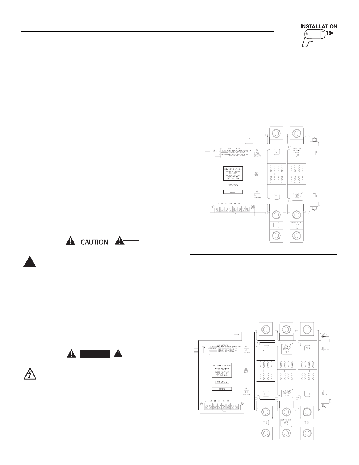
Wiring diagrams and electrical schematics are provided in this manual. Power source and load connections are made at a transfer mechanism, inside the
switch enclosure.
2.4.1 2-POLE MECHANISM
These switches (Figure 2.1) are used with a single
phase system, when the single phase NEUTRAL line
is to be connected to a Neutral Lug and is not to be
switched.
Figure 2.1 — Typical 2-Pole Transfer Mechanism
(200 Amp Shown)
2.4.2 3-POLE MECHANISM
These switches (Figure 2.2) are used with a three
phase system, when the three phase NEUTRAL line is
to be connected to a NEUTRAL lug and is not to be
switched. It is also used with a single phase system
when the neutral is to be switched (NEUTRAL to be
connected to third pole).
Figure 2.2 — Typical 3-Pole Transfer Mechanism
(200 Amp Shown)
◆
Section 2 — Installation
Generac GTS “W” Type Transfer Switch
!
DANGER
Page 6
4 Generac®Power Systems, Inc.
Solderless, screw-type terminal lugs are standard.
The conductor size range is as follows:
Conductor sizes must be adequate to handle the maximum current to which they will be subjected; based
on the 75°C column of tables, charts, etc. used to size
conductors. The installation must comply fully with
all applicable codes, standards and regulations.
Before connecting wiring cables to terminals, remove
any surface oxides from the cable ends with a wire
brush. All power cables should enter the switch next
to transfer mechanism terminals. If ALUMINUM conductors are used, apply corrosion inhibitor to conductors. Tighten terminal lugs to the torque values as
noted on the decal located on the inside of the door.
After tightening terminal lugs, carefully wipe away
any excess corrosion inhibitor.
All power cables should enter the switch next to the
transfer mechanism terminals.
Use a torque wrench to tighten the conductors, being sure not to overtighten, or damage to the switch base could occur. If undertightened, a loose connection would result,
causing excess heat which could damage the
switch base.
Connect power source load conductors to clearly
marked transfer mechanism terminal lugs as follows
1. Connect utility (NORMAL) power source cables to
switch terminals N1, N2, (N3).
2. Connect emergency (STANDBY) source power
cables to transfer switch terminals E1, E2, (E3).
3. Connect customer LOAD leads to switch termi-
nals T1, T2, T3.
Conductors must be properly supported, of approved
insulative qualities, protected by approved conduit,
and of the correct wire gauge size in accordance with
applicable codes.
Be sure to maintain proper electrical clearance
between live metal parts and grounded metal. Allow
at least 1/2 inch for 100-400 amp circuits.
2.5 CONNECTING START CIRCUIT
WIRES
Control system interconnections (Page 11) consist of
UTILITY 1 and 2, LOAD 1 and 2; and leads 23 and
194. Control system interconnection leads must be
run in a conduit that is separate from the AC power
lead. Recommended wire gauge sizes for this wiring
depends on the length of the wire, as recommended
below:
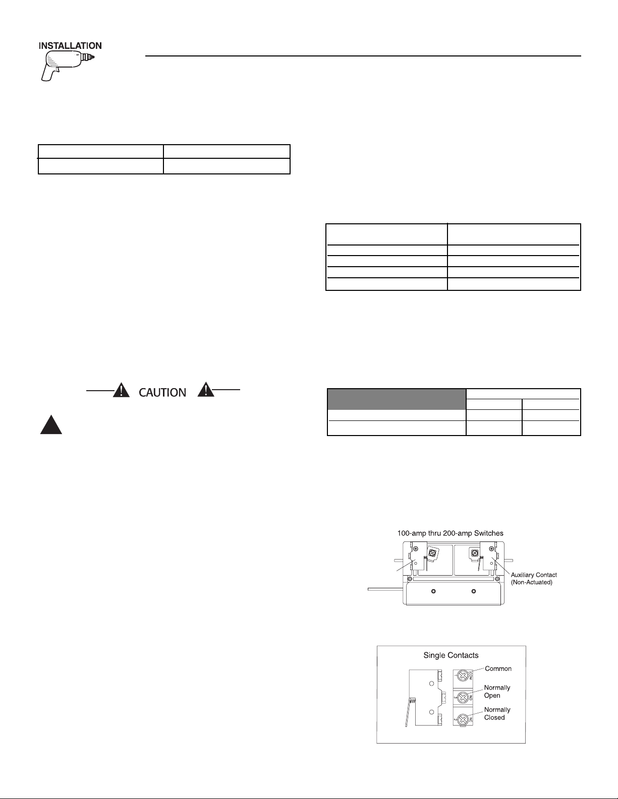
2.6 AUXILIARY CONTACTS
If desired, there are Auxiliary Contacts on the transfer switch to operate customer accessories, remote
advisory lights, or remote annunciator devices. A
suitable power source must be connected to the
COMMON (C) terminal. See Figure 2.3.
Contact operation is shown in the following chart:
NOTE:
Auxiliary Contacts are rated 10 amps at 125 or
250 volts AC. DO NOT EXCEED THE RATED
VOLTAGE AND CURRENT OF THE CONTACTS.
Figure 2.3 – Auxiliary Contacts
Section 2 — Installation
Generac GTS “W” Type Transfer Switch
MAXIMUM WIRE LENGTH RECOMMENDED WIRE
SIZE
460 feet (140m) No. 18 AWG.
461 to 730 feet (223m) No. 16 AWG.
731 to 1,160 feet (354m) No. 14 AWG.
1,161 to 1,850 feet (565m) No. 12 AWG.
Switch Position
Utility Standby
Common to Normally Open Open Closed
Common to Normally Closed Closed Open
Switch Rating Wire Range
200A #4-400 MCM
!
Optional
Auxiliary Contact
(Actuated)
Side views shown in Utility position
Page 7

Generac®Power Systems, Inc. 5
3.1 FUNCTIONAL TESTS AND
ADJUSTMENTS
Following transfer switch installation and interconnection, inspect the entire installation carefully. A
competent, qualified electrician should inspect it.
The installation should comply strictly with all applicable codes, standards, and regulations. When
absolutely certain the installation is proper and correct, complete a functional test of the system.
Perform functional tests in the exact order
presented in this manual, or damage to the
switch could be done.
IMPORTANT: Before proceeding with functional
tests, read and make sure you understand all
instructions and information in this section. Also
read the information and instructions of labels and
decals affixed to the switch. Note any options or
accessories that might be installed and review their
operation.
3.2 MANUAL OPERATION
Do NOT manually transfer under load.
Disconnect transfer switch from all power
sources by approved means, such as a main
circuit breaker(s).
A manual HANDLE is shipped with the transfer
switch. Manual operation must be checked BEFORE
the transfer switch is operated electrically. To check
manual operation, proceed as follows:
1. Turn the generator’s AUTO-OFF-MANUAL switch
to OFF.
2. Turn OFF both UTILITY and EMERGENCY
power supplies to the transfer switch, with whatever means provided (such as the main line circuit breakers).
3. Note position of transfer mechanism main con-
tacts by observing display windows in “A” and “B”
in Figure 3.1 on page 6 as follows:
• Window “A” ON, Window “B” OFF - LOAD terminals (T1, T2, T3) are connected to utility terminals (N1, N2, N3).
• Window “A” OFF, Window “B” ON - LOAD terminals (T1, T2, T3) are connected to emergency terminals (E1, E2, E3).
Do not use excessive force when operating
the transfer switch manually or the manual
handle could be damaged.
3.2.1 CLOSE TO NORMAL SOURCE SIDE
Before proceeding, verify the position of the switch by
observing window “A” in Figure 3.1 on page 6. If window “A” reads “ON”, the contacts are closed in the
normal position, no further action is required. If it
reads “OFF”, proceed with Step 1.
Step 1: With the handle attached to the actuating
shaft, move handle in the direction of the
arrow on the switch cover until it stops — DO
NOT FORCE. Release handle slowly to allow
the spring in the switch box to relax. “ON”
now appears in Window “A” and “OFF”
appears in Window “B”.
3.2.2 CLOSE TO EMERGENCY SOURCE SIDE
Before proceeding, verify the position of the switch by
observing window “B” in Figure 3.1 on page 6. If window “B” reads “ON”, the contacts are closed in the
EMERGENCY (Standby) position. No further action
is required. If it reads “OFF”, proceed with Step 1.
Step 1: With the handle attached to the actuating
shaft, move the handle in the direction of the
arrow on the switch cover until it stops - DO
NOT FORCE. Release handle slowly to allow
the spring in the switch box to relax. “OFF”
now appears in Window “A” and “ON” appears
in Window “B”.
3.2.3 RETURN TO NORMAL SOURCE SIDE
Manually actuate switch to return Window “A” to the
“ON” position.
3.3 VOLTAGE CHECKS
1. Turn ON the UTILITY power supply to the transfer switch with whatever means provided (such as
the UTILITY maim line circuit breaker).
PROCEED WITH CAUTION. THE TRANSFER
SWITCH IS NOW ELECTRICALLY HOT. CONTACT
WITH LIVE TERMINALS RESULTS IN EXTREMELY
HAZARDOUS AND POSSIBLY FATAL ELECTRICAL SHOCK.
2. With an accurate AC voltmeter, check for correct
voltage.
Single-phase utility supply:
Measure across ATS terminal lugs N1 and N2; N1
to NEUTRAL and N2 to NEUTRAL.
Three-phase utility supply:
Measure across ATS terminal lugs N1 to N2, N2
to N3, and N1 to N3.
Measure across ATS terminal lugs N1 to NEUTRAL, N2 to NEUTRAL, and N3 to NEUTRAL.
◆
◆
◆
!
Section 3 — Operation
Generac GTS “W” Type Transfer Switch
!
DANGER
!
DANGER
Page 8

6 Generac®Power Systems, Inc.
3. When certain that UTILITY supply voltage is correct and compatible with transfer switch ratings,
turn OFF the UTILITY supply to the transfer
switch.
4. On the generator panel, set the AUTO-OFFMANUAL switch to MANUAL position. The generator should crank and start.
5. Let the generator stabilize and warm up at noload for at least five minutes.
6. Set the generator's main circuit breaker (CB1) to
its ON or CLOSED position.
PROCEED WITH CAUTION. GENERATOR OUTPUT VOLTAGE IS NOW BEING DELIVERED TO
TRANSFER SWITCH TERMINALS. CONTACT
WITH LIVE TERMINALS RESULTS IN EXTREMELY
DANGEROUS AND POSSIBLY FATAL ELECTRICAL SHOCK.
7. With an accurate AC voltmeter and frequency
meter, check the no-load, voltage and frequency.
Single-phase generator supply:
Measure across ATS terminal lugs E1 to E2; E1
to NEUTRAL and E2 to NEUTRAL.
a. Frequency ......................................60-62 Hz
b. Terminals E1 to E2 ........................240-246 VAC
c. Terminals E1 to NEUTRAL ............120-123 VAC
d. Terminals E2 to NEUTRAL ............120-123 VAC
Three-phase generator supply:
Measure across ATS terminal lugs E1 to E2, E2
to E3 and E1 to E3.
Measure across ATS terminal lugs E1 to NEUTRAL, E2 to NEUTRAL and E3 to NEUTRAL.
a. Frequency ......................................60-62 Hz
b. Terminals E1-E2, E2-E3, E1-E3 ....208-212 VAC
c. Terminals E1-N, E2-N, E3-N ..........120-122 VAC
It will also be necessary to verify that the phase rotation of the utility matches the phase rotation of the
generator. This can be done by using a phase rotation
indicator.
Section 3 — Operation
Generac GTS “W” Type Transfer Switch
Figure 3.1 — Actuating Transfer Switch
DANGER
Page 9

Generac®Power Systems, Inc. 7
Failure to do so may result in damage to certain rotary equipment.
8. Set the generator’s main circuit breaker (CB1) to
its OFF or OPEN position.
9. Set the Auto/Off/Manual switch to the OFF position to shut down the generator.
NOTE:
Do NOT proceed until generator AC output voltage
and frequency are correct and within stated limits.
If the no-load voltage is correct but no-load frequency is incorrect, the engine governed speed
probably requires adjustment. If no-load frequency is correct but voltage is not, the voltage regulator may require adjustment.
3.4 GENERATOR TESTS UNDER LOAD
1. Set the generator's main circuit breaker to its
OFF or OPEN position.
2. Manually actuate the transfer switch main contacts to their emergency (Standby) position.
Refer to Manual Operation on page 5.
3. To start the generator, set the AUTO-OFFMANUAL switch to MANUAL. When engine starts,
let it stabilize for a few minutes.
4. Turn the generator's main circuit breaker to the
ON or CLOSED position. The generator now powers all LOAD circuits. Check generator operation
under load as follows:
• Turn ON electrical loads to the full rated
wattage/amperage capacity of the generator.
DO NOT OVERLOAD.
• With maximum rated load applied, check
voltage and frequency across transfer switch
terminals E1 and E2. Voltage should be
greater than 230 volts; frequency should be
greater than 59 Hz.
• Let the generator run under rated load for at
least 30 minutes. With unit running, listen for
unusual noises, vibration, overheating, etc.,
that might indicate a problem.
5. When checkout under load is complete, set main
circuit breaker of the generator to the OFF or
OPEN position.
6. Let the generator run at no-load for several
minutes. Then, shut down by setting the AUTOOFF-MANUAL switch to its OFF position.
7. Move the switch's main contacts back to the
UTILITY position. For example, load connected to
utility power supply. Refer to Manual Operation
on page 5. Handle and operating lever of transfer
switch should be in down position.
8. Turn on the utility power supply to transfer
switch, using whatever means provided (such as
a utility main line circuit breaker). The utility
power source now powers the loads.
9. Set the generator's AUTO-OFF-MANUAL switch to
its AUTO position. The system is now set for fully
automatic operation.
!
Section 3 — Operation
Generac GTS “W” Type Transfer Switch
Page 10

8 Generac®Power Systems, Inc.
Section 4 — Mounting Dimensions
Generac GTS “W” Type Transfer Switch
Mounting Dimensions – Drawing No. 0D3714-B
490
430
A
A
514
A
A
612
Values are in Millimeters
Note: Diameter of Mounting holes (A) is 6.35 MM
180
Page 11

Generac®Power Systems, Inc. 9
@
50
,
,
:
(
)
(
)
,
(
)
(
)
U
TRAL
C
O
U
S
CH
SU
H
C
SCO
C
O
194
23
LO
UTILITY
UTILITY
G
O
O
S
S
S
C
S
US
E
O
CO
U
S
(
)
LO
O
S
(
)
Section 5 — Electrical Data
Generac GTS “W” Type Transfer Switch
Interconnection Diagram - Drawing No. 074106-B
E
N
TI
NNE
N1
N2
T1
TILITY 1
TILITY 2
OAD 2 (T2)
OAD 1
4
B1
R
L PANEL
ENERAT
NTR
AND
T1
.
IT
H
ND
AND
WIT
T B
FER
M
TE:
WER LEAD
N IN TW
IFFERENT
RAN
EAD
TE
TRAL
E
T
NNE
PPLY WIT
E DI
TILITY
ERVI
MER
T
AD
IN THE GENERATOR CONTROL PANEL DO NOT CONNECT THESE
FAILURE OF THE CONTROL BOARD WILL OCCUR IF CONNECTED.
T2
IRES
OAD 2
F THERE ARE NO MATCHING TERMINAL CONNECTIONS FOR LOAD 1
FER
RAN
WIT
AD 2
AD 1
2
1
T
TE TE
OPTIONAL
EM
WITCH
OPEN SWITCH TO TEST -
SPST
Vac MIN.
2
A
WITCH TYPE
LECTRICAL RATINGS
Page 12

C
6
9
05
6
3
94
3
94
D
S
S:
A
H
Y
.
S2
S3
S1
L
OR
R
R
)
6
G
10 Generac®Power Systems, Inc.
Section 5 — Electrical Data
Generac GTS “W” Type Transfer Switch
200 Amp, 2-pole Switch – Drawing No. 0D3819-A
12
12
T
2
L
L
L
LEGEN
- CONTACTOR ACTUATING COI
TS - TRANSFER SWITCH CONTACT
TR - RELAY, TRANSFE
TS - TERMINAL STRIP (CUSTOMER CONNECTION
LS1,LS2,LS3 - LIMIT SWITCHES, ACTUATO
F1,F2 - FUSE 5A SENSIN
T
2
1
2
1
NOTE
LL CONTACTS SHOWN WIT
TRANSFER SWITCH IN UTILIT
POSITION
Page 13

Generac®Power Systems, Inc. 11
S
6
05
05
6
05
S
94
3
3
94
3
94
3
94
Section 5 — Electrical Data
Generac GTS “W” Type Transfer Switch
200 Amp, 2-pole Switch – Drawing No. 0D3819-A
T
2
12
12
2
1
2
2
2
1
2
1
2
1
T
4
TILITY 1
TILITY 2
Page 14

05
6
3
94
3
94
D
S
S:
H
Y
.
S2
S3
S1
L
OR
R
Y
R
)
3
6
G
M
8.
,
12 Generac®Power Systems, Inc.
Section 5 — Electrical Data
Generac GTS “W” Type Transfer Switch
200 Amp, 3-pole Switch – Drawing No. 0D3818-A
12
12
T
N
2
L
L
L
T
E
LEGEN
- CONTACTOR ACTUATING COI
TS - TRANSFER SWITCH CONTACT
PM - POWER MONITOR, 3 PHASE UTILIT
TR - RELAY, TRANSFE
TS - TERMINAL STRIP (CUSTOMER CONNECTION
LS1,LS2,LS3 - LIMIT SWITCHES, ACTUATO
F1,F2 - FUSE 5A SENSIN
2
1
NOTE
1.) ALL CONTACTS SHOWN WIT
TRANSFER SWITCH IN UTILIT
POSITION
2.) FOR SINGLE PHASE OPERATION
ADD JUMPER WIRE FROM P
TERMINALS 1 TO
2
1
Page 15

Generac®Power Systems, Inc. 13
S
6
05
05
3
3
3
6
05
3
3
3
S
3
3N3
94
3
3
94
3
94
Section 5 — Electrical Data
Generac GTS “W” Type Transfer Switch
200 Amp, 3-pole Switch – Drawing No. 0D3818-A
T
N
N
E
1
2
12
1
2
N
2
T
N
12
2
2
2
1
N
2
1
N
T
4
TILITY 1
TILITY 2
Page 16

C
S
O
US
O
O
U
SS
,
,
S
S
CH
,
C
O
S
S
S
3
3
LO
LO
194
23
U
L
S
0C790
S
0C7907H-S
0C7907H-S
)
A
C
OSU
5
5
0A9949-S
0A9949S
0A9949-T
0A9949T
/S
C
/
0633
0A9949-S
0
0A9949S
S
s
ed
use
o
sa
e
p
g
3587
T-T
0A9949-T
0A9949T
14 Generac®Power Systems, Inc.
Section 6 — Exploded Views and Parts List
Generac GTS “W” Type Transfer Switch
200 A, 2Pole Switch Assembly – Drawing No. 0E2868$-D
TRA
E
N
TILITY
7
4
RE
L
N
-
1
E4
TEM
EMBLY
Y
E WITH
53187
WIT
LE A
R
WER
AND #083494
D
FER
F
P
L M
H I
RAN
AUKESHA WI
#075595
NTR
WIT
ENERA
079844
m
f
f
t
eplace with UL
ype and ratin
i
-
.
00 Volt, 5 am
AD 2
D
AD 1
GROUND LUG ASSEMBLY
H
21
WIT
N
1
2
PPLIED W
ANDLE P
4
7H-
0A9949-
D4
4-L
Page 17

Generac®Power Systems, Inc. 15
Section 6 — Exploded Views and Parts List
Generac GTS “W” Type Transfer Switch
200 A, 2Pole Switch Assembly – Drawing No. 0E2868$-D
ITEM PART NO. QTY. DESCRIPTION
1 0C8884 1 XFER SW-W 200A600V2P
20A9949 6 LUG SLDLSS 400-#4X1/4-20 CU7AL
3 0C4896 6 SCREW FHM M8-1.25 X 20MM CR
4 067989 6 NUT LOCK FL M8-1.25 YEL CHR
5 026902 6 SCREW HHTT #8-32 X 1/4 CZ
6 0C7907H 2 COVER LUG 2P 150/200AMP
7 022127 1 NUT HEX 1/4-20 STEEL
8 057329 1 LUG SLDLSS 350-#6X13/32 AL/CU
9 027482 1 WASHER SHAKEPROOF EXT 5/16 STL
10 022097 3 WASHER LOCK M6-1/4
11 0C8275 4 SCREW PPHM DSEMS M4-7 X 10 ZNC
12 073591 4 FUSE HOLDER
13 090388 5 SCREW HHTT M6-1.0 X 12 ZINC
14 0A1495 6 SCREW HHTT M4-0.7 X 10 BP
15 063617 1 RELAY PNL 12VDC DPDT 10A@240VA
16 0C2454 2 SCREW TH-FRM M6-1X16 N WA Z/JS
17 0A1661 2 RIVET POP .156 X .675 AL
18 0C4449A 1 ASS'Y-NTRL BL150-200A
19 0E2865 1 WELDMENT,TRANSFER SWITCH BOX
20 0D3718 1 COVER, TRANSFER SWITCH BOX
21 0C8308 2 DECAL TERMINAL SHOCK HAZARD
22 0A2595 1 DECAL TERMINAL STRIP
23 022264 6 WASHER LOCK #8-M4
24 0E4313 1 DECAL,SWITCH RATING
25 064101 4 NUT LOCK FL 3/8-16
26 0E2866 1 SUBPLT 200A TS 3R
27 025870 1 NUT WING 1/4-20
28 063378 5 HOLDER CABLE TIE
29 064761 5 TIE WRAP UL 5.6 X .10 NATL
30 063321 1 HANDLE XFER SWITCH 1-400A
31 073590A 4 FUSE 5A X BUSS
32 0D3587 1 DECAL, FUSE REPLACEMENT
33 067210A 1 DECAL GROUND LUG
34 0A9457 1 DECAL NEUTRAL
35 0D4545 1 DECAL, MANUAL OPERATION
36* 0E4307 1 DECAL,TEST SEQUENCE 2P TS 3R
37 081221 1 DECAL-UL LIST HSB
38** 0E4358 2 DECAL,LUG TORQUE INFO
39*** 0E5567 1 DECAL,TRANSFER SWITCH
40 022129 1 WASHER LOCK M8-5/16
* CENTER DECAL ON INSIDE OF THE COVER (ITEM #20)
** INSTALL ACROSS E & N TERMINALS
***INSTALL ON FRONT OF THE COVER (ITEM #20)
Page 18

16 Generac®Power Systems, Inc.
A9949-S
A9949S
0A9949-S
C790
S
5
5
C7907DS
S
0A9949-S
0A9949S
C
CS
C
U
/
0633
/S
C
with
UL
s
ed
use
o
sa
e
p
g
358
UT
)
A
,
S
O
G
U
Q
C
OSU
Section 6 — Exploded Views and Parts List
Generac GTS “W” Type Transfer Switch
200 A, 3-pole Switch Assembly – Drawing No. 0E4312$-F
UE ITEMS
OTE: TOR
E
7
4
RE
L
A
L
VA
VA
E
LTA
MBER
TEM V
Y
ERIAL N
WI.
AUKESHA
7
D
.
m
f
f
t
00 Volt, 5 am
ype and ratin
i
-
H
21
N
WIT
1
2
N
ANDLE P
GROUND LUG ASSEMBLY
PPLIED W
4
7D-
-L
D4
Page 19

Generac®Power Systems, Inc. 17
ITEM PART NO. QTY. DESCRIPTION
1 0C8885 1 XFER SW-W 200A600V3P
20A99499LUG SLDLSS 400-#4X1/4-20 CU7AL
3 0C4896 9 SCREW FHM M8-1.25 X 20MM CR
4 0679899NUT LOCK FL M8-1.25 YEL CHR
5 026902 7 SCREW HHTT #8-32 X 1/4 CZ
6 0C7907D 2 COVER LUG 3P 150/200AMP
7 045771 1 NUT HEX M8-1.25 G8 CLEAR ZINC
8 057329 1 LUG SLDLSS 350-#6X13/32 AL/CU
9 027482 1 WASHER SHAKEPROOF EXT 5/16 STL
10 022097 3 WASHER LOCK M6-1/4
11 0C8275 4 SCREW PPHM DSEMS M4-7 X 10 ZNC
12 073591 2 FUSE HOLDER
13 090388 5 SCREW HHTT M6-1.0 X 12 ZINC
14 0A1495 6 SCREW HHTT M4-0.7 X 10 BP
15 063617 1 RELAY PNL 12VDC DPDT 10A@240VA
16 047411 2 SCREW HHC M6-1.0 X 16 G8.8
17 0A1661 2 RIVET POP .156 X .675 AL
18 0C4449A 1 ASS'Y-NTRL BL150-200A
19 0E2865 1 WELDMENT,TRANSFER SWITCH BOX
20 0D3718 1 COVER, TRANSFER SWITCH BOX
21 0C8308 2 DECAL TERMINAL SHOCK HAZARD
22 0C2262 1 DECAL TERMINAL STRIP
23 0F6165 2 WASHER M6 NYLON
24 0F5569 1 DECAL,SWITCH RATING
25 064101 4 NUT LOCK FL 3/8-16
26 0E2866 1 SUBPLT 200A TS 3R
27 087680 1 NUT WING M6-1.0
28 063378 5 HOLDER CABLE TIE
29 064761 5 TIE WRAP UL 5.6 X .10 NATL
30 063321 1 HANDLE XFER SWITCH 1-400A
31 073590A 2 FUSE 5A X BUSS
32 0D3587 1 DECAL, FUSE REPLACEMENT
33 067210A 1 DECAL GROUND LUG
34 0A9457 1 DECAL NEUTRAL
35 0D4545 1 DECAL, MANUAL OPERATION
36* 0E4307 1 DECAL,TEST SEQUENCE 2P TS 3R
37 081221 1 DECAL-UL LIST HSB
38 0A2284 2 SCREW SWAGE 8-32 X 1/2 Z/YC
39 063306 1 3-PHASE POWER MONITR
40 066972 1 SOCKET RELAY OCTAL 8P 300V-10A
41** 0E4358 2 DECAL,LUG TORQUE INFO
42*** 0F6521 1 DECAL TRANSFER SWITCH RTS
43 022129 1 WASHER LOCK M8-5/16
* CENTER DECAL ON INSIDE OF THE COVER (ITEM #20)
** INSTALL ACROSS E & N TERMINALS
***INSTALL ON FRONT OF THE COVER (ITEM #20)
Section 6 — Exploded Views and Parts List
Generac GTS “W” Type Transfer Switch
200 A, 3-pole Switch Assembly – Drawing No. 0E4312$-F
Page 20

Part No. 0E4334 Revision C (05/05/05) Printed in U.S.A.
Section 7 — Warranty
Generac GTS “W” Type Transfer Switch
GENERAC POWER SYSTEMS STANDARD TWO-YEAR LIMITED WARRANTY
FOR GENERAC TRANSFER SWITCH SYSTEMS
NOTE: ALL UNITS MUST HAVE A START-UP INSPECTION PERFORMED BY AN AUTHORIZED GENERAC DEALER.
For a period of two (2) years or two thousand (2,000) hours of operation from the date of sale, which ever occurs first, Generac Power Systems, Inc. will, at its
option, repair or replace any part(s) which, upon examination, inspection, and testing by Generac Power Systems or an Authorized/Certified Generac Power
Systems Dealer, or branch thereof, is found to be defective under normal use and service, in accordance with the warranty schedule set forth below. Any equipment that the purchaser/owner claims to be defective must be examined by the nearest Authorized/Certified Generac Power Systems Dealer, or branch thereof.
This warranty applies only to Generac Power Systems Transfer Switch used in "Standby" applications, as Generac Power Systems, Inc. has defined Transfer
Switch applications, provided said generator has been initially installed and/or inspected on-site by an Authorized/Certified Generac Power Systems Dealer, or
branch thereof. Scheduled maintenance, as outlined by the generator owner's manual, must be performed by an Authorized/Certified Generac Power Systems
Dealer, or branch thereof. This will verify service has been performed on the unit throughout the warranty period. This warranty is limited to and available only on
Liquid-cooled units.
W
ARRANTY SCHEDULE
YEAR ONE — One hundred percent (100%) coverage on mileage, labor, and parts listed.
• ALL COMPONENTS
YEAR TWO — One hundred percent (100%) coverage on parts listed.
• ALL COMPONENTS — PARTS ONLY
Guidelines:
Travel allowance is limited to 300 miles maximum, and 7.5 hours maximum (per occurrence), round trip, to the nearest authorized Generac Service Facility, and
only applies to permanently wired and mounted units.
• Any and all warranty repairs and/or concerns, must be performed and/or addressed by an Authorized/Certified Generac Power Systems Dealer, or branch
thereof.
• A Generac Power Systems, Inc. Transfer Switch is highly recommended to be used in conjunction with the generator set. If a Non-Generac Power Systems,
Inc. Transfer Switch is substituted for use and directly causes damage to the generator set, no warranty coverage shall apply.
• All warranty expense allowances are subject to the conditions defined in Generac Power Systems Warranty, Policies, Procedures and Flat Rate Manual.
• Units that have been resold are not covered under the Generac Power Systems Warranty, as this Warranty is not transferable.
• Unit enclosure is only covered during the first year of the warranty provision.
• Use of Non-Generac replacement part(s) will void the warranty in its entirety.
• Engine coolant heaters (block-heaters), heater controls and circulating pumps are only covered during the first year of the warranty provision.
THIS WARRANTY SHALL NOT APPLY TO THE FOLLOWING:
1. Any unit built/manufactured prior to July 1, 2004.
2. Costs of normal maintenance (i.e. tune-ups, associated part(s), adjustments, loose/leaking clamps, installation and start-up).
3. Any failure caused by contaminated fuels, oils, coolants/antifreeze or lack of proper fuels, oils or coolants/antifreeze.
4. Units sold, rated or used for "Prime Power", "Trailer Mounted" or "Rental Unit" applications as Generac Power Systems has defined Prime Power, Trailer
Mounted or Rental Unit. Contact a Generac Power Systems Distributor for Prime Power, Trailer Mounted or Rental Unit definition and warranty.
5. Failures caused by any external cause or act of God such as, but not limited to, collision, fire, theft, freezing, vandalism, riot or wars, lightning, earthquake,
windstorm, hail, volcanic eruption, water or flood, tornado, hurricane, terrorist acts or nuclear holocaust.
6. Products that are modified or altered in a manner not authorized by Generac Power Systems in writing.
7. Failures due, but not limited to, normal wear and tear, accident, misuse, abuse, negligence, or improper installation or sizing.
8. Any incidental, consequential or indirect damages caused by defects in materials or workmanship, or any delay in repair or replacement of the defective
part(s).
9. Damage related to rodent and/or insect infestation.
10. Failure due to misapplication, misrepresentation, or bi-fuel conversion.
11. Telephone, facsimile, cellular phone, satellite, Internet, or any other communication expenses.
12. Rental equipment used while warranty repairs are being performed (i.e. rental generators, cranes, etc.).
13. Overtime, holiday, or emergency labor.
14. Modes of transportation deemed abnormal (refer to Generac Power Systems Warranty, Policies, Procedures and Flat Rate Manual).
15. Steel enclosures that are rusting due to improper installation, location in a harsh or saltwater environment or scratched where integrity of paint applied is
compromised.
16. Any and all expenses incurred investigating performance complaints unless defective Generac materials and/or workmanship were the direct cause of the
problem.
17. Starting batteries, fuses, light bulbs, engine fluids, and overnight freight cost for replacement part(s).
THIS WARRANTY IS IN PLACE OF ALL OTHER WARRANTIES, EXPRESSED OR IMPLIED, SPECIFICALLY, GENERAC POWER SYSTEMS MAKES NO
OTHER WARRANTIES AS TO THE MERCHANTABILITY OR FITNESS FOR A PARTICULAR PURPOSE. Some states do not allow limitations on how long an
implied warranty lasts, so the above limitation may not apply to purchaser/owner.
GENERAC POWER SYSTEMS ONLY LIABILITY SHALL BE THE REPAIR OR REPLACEMENT OF PART(S) AS STATED ABOVE. IN NO EVENT SHALL GENERAC POWER SYSTEMS BE LIABLE FOR ANY INCIDENTAL, OR CONSEQUENTIAL DAMAGES, EVEN IF SUCH DAMAGES ARE A DIRECT RESULT OF
GENERAC POWER SYSTEMS, INC. NEGLIGENCE.
Some states do not allow the exclusion or limitation of incidental or consequential damages, so the above limitations may not apply to purchaser/owner.
Purchaser/owner agrees to make no claims against Generac Power Systems, Inc. based on negligence. This warranty gives purchaser/owner specific legal
rights. Purchaser/owner also may have other rights that vary from state to state.
Generac Power Systems, Inc. • P.O. Box 8 • Waukesha, WI 53187
Ph: (262) 544-4811 • Fax: (262) 544-4851
Bulletin 0166260SBY / Printed in U.S.A. 6.04
 Loading...