

Page 1
7300 Series
Operating Manual
Genelec 7360A and 7370A
Smart Active Subwoofers
750-7360A/7370A
Page 2

Genelec 7360A and 7370A Smart Active Subwoofers
Introduction
Congratulations and a thank-you for the
purchase of this Genelec 7300 series
subwoofer. This manual addresses setting
up and using the Genelec 7360A and 7370A
subwoofers. These subwoofers are designed
to integrate easily into all environments, both
those using analog audio as well as those
using digital AES/EBU audio. Genelec 7360A
and 7370A subwoofers are designed for
precise monitoring of multichannel analog
audio signals and stereo AES/EBU signals.
Multichannel AES/EBU signal can be
monitored by using the 9301 multichannel
digital audio interface device connected to
the subwoofer.
Energy saving Intelligent Signal Sensing
(ISS) can be turned on to put the subwoofer
automatically into a standby state when
audio signal has been absent for a selected
time. In the standby mode the product
consumes less than one Watt of power.
Upon sensing an input signal the subwoofer
automatically wakes up to full operation.
The wait until entering the ISS power save
can be congured using the GLM software.
When the ISS is active you can have your
monitoring system ready for action at all
times.
Installation
Each subwoofer is supplied with a mains
cable, one 5 m GLM network cable, mains
cable, and an operating manual. Before
connecting switch the subwoofer and
monitors o.
Connections
Seven balanced XLR input/output pairs
are available for analog signals (see Figure
1). There is a dedicated LFE In and LFE
Out. The Link In and Link Out connectors
can be used to for daisy-chaining multiple
subwoofers with minimum cable count. In
addition to these analog signal connectors,
digital audio in and out connectors
supporting AES/EBU format are available.
The digital out connector can be used to
daisy chain multiple subwoofers while digital
audio is being used.
Multichannel AES/EBU signal can be
monitored by using the 9301 multichannel
digital audio interface device connected to
the subwoofer.
Two CAT5 (RJ45) GLM Network
connectors are available for computer
control using the Genelec Loudspeaker
Manager (GLM) software.
Bypass connector supports a ¼ in
jack switch-operated subwoofer bass
management bypass function when the xed
85 Hz subwoofer crossover is used.
The mains input supports a wide mains
voltage range (100-240 VAC, 50-60 Hz)
and enables the subwoofer to be plugged
in anywhere globally. If the mains power is
provided with a generator, inverter or certain
lower-quality UPS devices, we recommend
filtering of the mains power voltage
harmonics and taking care that the voltage
supply is stable.
Bass Management
Bass management splits the signal from
each input into low and high frequency
components. Signal content below the
crossover frequency is reproduced by the
subwoofer and signal content above the
crossover frequency is reproduced by the
monitors connected to the outputs of the
subwoofer.
The 7360A and 7370A offer two bass
management methods:
Centralized bass management
This method builds both the highpass and
the lowpass lters in the subwoofer and can
be used in all setups, with or without GLM
control. A xed 85 Hz crossover lter for the
analog main channels is default for manual
use.
In this method all analog signal cables
are routed through the subwoofer's IN/
OUT connectors to the respective main
monitor
s.
Distributed bass management
In this method the lowpass lter is applied
in the subwoofer and the highpass lter in
the monitor, and these are set in synchrony
using the GLM control network. This method
is only available in systems where GLM is
used.
The GLM software enables adjusting the
subwoofer/monitor crossover from 50 Hz to
100 Hz when distributed bass management
is used.
The distributed bass management
supports three different signal cabling
congurations:
• All channels routed through the
subwoofer's IN/OUT connectors to the
respective monitors.
• Y-cables from the source to the
subwoofer's IN connector and the
monitor's signal input.
• Signal sources with dual outputs for each
channel.
Using With GLM™
Control Network
Subwoofers are fully compatible with
Genelec Loudspeaker Manager GLM™ and
the proprietary Genelec monitor control
network and Genelec SAM monitors. Using
the GLM control method unleashes the full
room compensation power in the subwoofer,
with 20 parametric room compensation
lters. This level of room compensation detail
is only available when the GLM is used. Use
with the GLM™ network is described in the
DSP System Operating Manual.
System setup
Although the subwoofer can be used without
the GLM™ software and control network,
they only reach their full potential when
set up and calibrated using the GLM™
software. Genelec Loudspeaker Manager
GLM™ and the proprietary Genelec
monitor control network offer automated
acoustic equalization and alignment for any
reproduction system from simple stereo to
very complex 3D immersive setups including
also one or more subwoofers. GLM setup is
fast and accurate and can precisely address
the typical narrow-band low frequency mode
resonances of a room. The settings can be
controlled with a computer or be permanently
stored in the monitors to make the setup
available at all times even when a computer
is not in use. Genelec recommends setting
up SAM monitoring systems using GLM. You
can nd a detailed description of the setup
and the use of GLM™ in the GLM™ System
Operating Manual.
Page 3
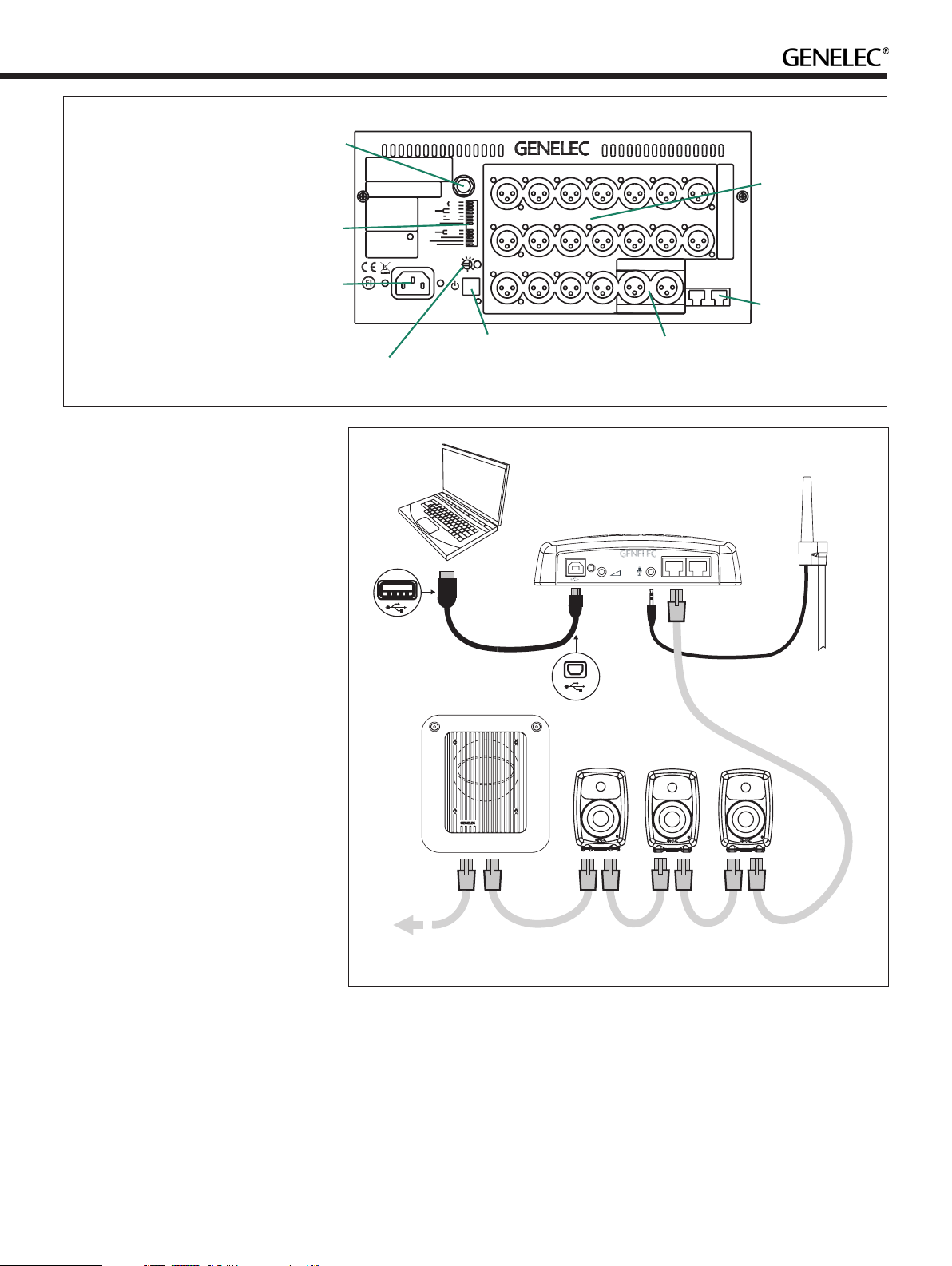
IN/OUT
BYPASS
SWITCH
CONNECTOR
CONTROL
SWITCHES
MAINS
INPUT
AVERTISSEMENT
RISQUEDECHOCÉLECTRIQUE. NEPAS OUVRIR.NE PAS
EXPOSERÀL'EAUOUL'HUMIDITÉ. AUCUNCOMPOSANTÀ
L'INTÉRIEURREMPLAÇABLE PARL'UTILISATEUR.ADRESSER
TOUTERÉPARATIONÀUNPERSONNELQUALIFIÉ.
CETAPPAREILDOIT ÊTRERACCORDÉÀLATERRE.
LAITEON LIITETTÄVÄSUOJAKOSKETTIMILLA
VARUSTETTUUNPISTORASIAAN.
APPARATETMÅTILKOPLES JORDETSTIKKONTAKT.
APPARATENSKALLANSLUTAS TILLJORDATUTTAG.
WARNING
ELECTRICSHOCK HAZARD.DO
NOTOPEN. DONOT SUBJECT
TOWATER ORMOISTURE. NO
USERSERVICEABLE PARTS
INSIDE.REFER SERVICINGTO
QUALIFIEDPERSONNEL. USE
EARTHEDMAINS CONNECTION
ONLY.
THISDEVICE COMPLIES
WITHFCCPART15AND
CANADIANICES-003 RADIO
FREQUENCYCLASSBEMISSION
REQUIREMENTS.REFER TO
OPERATINGMANUAL FORFULL
INFORMATION.
www.genelec.com
MADEIN FINLAND
MAINSINPUT
50/60Hz300W
100-240V~
BASSROLL-OFF
PHASE
DIGITALLFE
LFECHANNEL
LFE+10 dB
LEVEL
TESTTONE
ISS
STORED
INPUTdBu
PRODUCING
100dB SPL(1 m)
BYPASS
-4dB
-8dB
-90°
-180°
ON/OFF
A/B
-10dB
-20dB
0
+2
+4 +12
RESETTO FACTORY
SETTINGS:PUSH
BUTTONFOR 10 SEC
ONOFF
-2
-4
-6
+8
7360ASMART ACTIVE SUBWOOFER
IN 6IN7
OUT 6 OUT 7
ANALOGANALOGANALOG
IN 3IN4
OUT 3 OUT 4
IN 1IN2
OUT 1
TEST 1
OUT 2
TEST 2
LFE IN
OUT
IN 5
DIGITAL
LFE OUT
OUT 5
IN
LINK IN
LINK OUT
GLM NETWORK
SERIAL
NUMBER
ANALOG
CONNECTORS
GLM NETWORK
CONNECTORS
Figure 1. Connector panel
of the 7360A. The 7370A
is similar.
The setup is fast and consists of the
following steps:
• Connect a CAT5 (RJ45) cable between
each monitor (and subwoofer) and nally
to the control network input of the GLM
Adapter device (see Figure 1).
• Connect the GLM Adapter device to
computer USB connector.
• Using a microphone stand, place the
Genelec measurement microphone at the
listening location with the microphone
pointing upwards and the microphone
top at the height of the engineer’s ear.
The microphone is a part of the GLM
User Kit.
• Connect the microphone cable to the
microphone input in the GLM Adapter
device.
• Download the GLM software at the
Genelec web site (www.genelec.com).
• Install the GLM software and follow the
instructions in the software to measure
and set up your system.
• If you plan to not use a computer for
controlling the monitors, use the GLM
software to write the setting into the
monitors (use menu item “Store | Store
the Current Group Settings…”).
ROTARY
LEVEL
ADJUSTMENT
POWER
SWITCH
COMPUTER
RUNNING
GLMSOFTWARE
AES/EBU IN/OUT
CONNECTORS
GLM ADAPTER
USB CABLE
SUBWOOFER
Figure 2. GLM Network cabling. Audio cabling not shown.
GLM
MONITORS
MICROPHONE
PLACED IN
THE LISTENING
292-0063
TERMINATOR
GLM NETWORK
CABLE
POSITION
While the GLM network is disconnected
the settings stored using the Genelec
Loudspeaker Manager software can be
selected in use by setting the STORED
switch ON.
Using Without GLM
Cabling
The 7300 series subwoofers can be easily set
up using the xed 85 Hz analogue crossover
filter. This fixed crossover filter is on as
a factory setting and highpass filters the
analogue outputs on the subwoofer. When
using this method, run each signal cable rst
to the subwoofer. Then, run the respective
output to the monitor. This monitor feed
signal is highpass ltered at 85 Hz.
When using the LFE signal, run the LFE
signal to the subwoofer LFE in connector.
When daisy-chaining multiple
subwoofers, run a cable from the Link Out
connector the next subwoofer’s Link In
Page 4

connector. When using the LFE signal, also
Phase Difference: 270°
Phase Difference: 90°
run a cable from the LFE Out to the next
subwoofer’s LFE In.
Control Switches
BASS ROLL-OFF controls compensate for
the very low frequency boost, reducing the
20 Hz level in 4 dB steps. The settings add
to a total of 12 dB attenuation. Setting both
switches to "OFF" obtains a at response.
PHASE switches can put the subwoofer
in phase with a selected main monitor.
Incorrect phase alignment can cause a drop
in level at the crossover frequency. See
chapter "Setting the Phase Switches."
Digital LFE switch selects the low pass
frequency for the subframe selected to
reproduce LFE (see "LFE CHANNEL" below).
The frequencies are 85 Hz for "OFF" and 150
Hz for "ON."
LFE CHANNEL A/B selects which subframe
carries the LFE signal. "ON" for A, "OFF" for
B. If A is selected for LFE, the B subframe is
assumed to carry main channel audio.
LFE +10 dB function adds +10 dB of
gain. See chapter "Using the LFE +10 dB
function."
LEVEL switches scale down the subwoofer
output level. The switch settings add up and
combine with therotary level adjustment
control.
TEST TONE switch activates the 85 Hz test
tone used for calibrating the phase. See
chapter "Setting the Phase Switches."
ISS switch activates the signal sensing
automatic energy saving function.
STORED switch selects the settings stored
inside the memory of the subwoofer and
settings made by the subwoofer's controls.
The stored settings are set using the GLM
Loudspeaker Manager Software and the
GLM control network and provide superior
functionality compared to subwoofer's
own controls.
Connector Panel Light
Normally, the light on the connector panel is
green, indicating normal operational mode.
Phase Difference: 0°
85 Hz
Phase Difference: 180°
85 Hz
Figure 3. The eect of phase dierence between the subwoofer and the main monitors
Red colour indicates amplier clipping and
yellow indicates thermal overload.If the red
or yellow warning light appears, turn down
the level.
85 Hz
85 Hz
Power up the system and set the TEST
TONE switch to "ON." Now you can hear an
85 Hz test signal from the subwoofer and
the main monitor connected to the center
channel output.
Setting the Phase Switches
Incorrect phase alignment between main
monitors and subwoofer causes a drop
in the frequency response of the whole
system at the crossover frequency. Figure 3
shows the eect of phase dierence to the
frequency response.
The phase dierence between the main
monitors and subwoofer at the listening
position depends on the position of the
subwoofer, so the phase adjustment should
be done only after the preferred position is
found and subwoofer and monitor levels
have been aligned. GLM software control
adjusts the phase automatically, but if GLM
is not available, the following manual phase
matching can be applied.
Manual Phase
Adjustment Method
Genelec 7360A and 7370A subwoofers are
equipped with a built-in 85 Hz frequency
test tone generator for phase alignment.
The test tone generator is connected to
the subwoofer's "TEST 1" output. Connect
temporarily the monitor to this output for
manual phase alignment.
1. Toggle the -180° phase switch on and o,
and set it to the position which gives the
lowest sound level at the listening position.
2. Next toggle the -90° phase switch on and
o, and again set it to the position which
gives the lowest sound level.
3. Finally, set the -180° phase switch to
the opposite setting and deactivate the
test signal. The phase adjustment is now
complete.
Using the LFE +10 dB
Function
Dolby Digital and DTS encoding formats
present the LFE channel with +10 dB gain
relative to the main channels. Surround
sound decoders may automatically add +10
dB of LFE gain to restore the level balance.
The “LFE +10 dB” function can add the
+10 dB of gain to the LFE channel in the
production stage if it is not already done
by the source connected to the monitoring
system. Switching the “LFE +10 dB” switch
to the “ON” position activates the function.
If the LFE output is at a 10 dB higher level
than other (non-LFE) channels, this switch
Page 5

should be set to “OFF”.
The “LFE +10 dB” function should not be
used in the following cases:
• If the +10 dB LFE gain is already
implemented by another device, for
example, a surround sound processor
or the output matrix of a mixing console.
• When producing an audio format
that does not require the use of +10 dB
gain on the LFE channel.
Additional Information
Positioning Subwoofer in Room
The location of the subwoofer can affect
the frequency response and sound level
dramatically particularly when the room
acoustic effects are strong. Even small
changes in a subwoofer's location can
make a marked dierence in the frequency
response. To begin, place the subwoofer
at the front wall slightly offset from the
room center line. Often methodical
experimentation is needed to find the
location giving the flattest frequency
response at the listening location. Usually
the subwoofer is placed close to a wall as
this usually creates the highest output.
Positioning the subwoofer close to a corner
will boost the bass level at lower frequencies
and may also cause asymmetrical spatial
imaging. Measured from the subwoofer's
driver the recommended distance to a wall
is less than 0.6 m (24 in). Cancellations from
the wall are then avoided.
Operating Environment
These subwoofers are designed for
indoor use only. The permissible ambient
temperature is 15-35 degrees Celsius
(50-95°F) and relative humidity 20% to
80% (noncondensing). When the product
has been stored or transported in cool
environment and is taken into a warm room,
wait 0.5-1 hours before opening packing to
prevent condensation of humidity before
connecting to mains power.
Minimum Clearances
Do not cover the grille or place the
subwoofer so that there is less than 0.1
m (4 in) of free space in front of the grille.
The space must be ventilated or suciently
large to dissipate heat so that the ambient
temperature does not rise above 35
degrees Celsius (95°F). Make sure that the
space under the subwoofer allows air ow.
Thick carpets may block ventilation needed
for cooling the electronics. The reex port
opening should have a clearance of at least
7.5 cm (3 in) to ensure functioning of the
reex port.
Flush Mounting
When the subwoofer is ush mounted in a
wall or cabinet, ensure unrestricted airow
in the reflex port and amplifier cooling.
Make the recess 7.5 cm (3 in) wider than the
subwoofer. Place the subwoofer to the right
side of the recess if the driver is facing the
room. This leaves sucient free space at
the reex port side. The height and depth of
the recess should not be much bigger than
needed for ventilation as this may cause
unwanted acoustic eects.
Maintenance
There are no user serviceable parts inside
the subwoofer. Maintenance or repair must
only be done by a Genelec certied service.
Guarantee
Genelec guarantees the subwoofers for
two years against manufacturing faults or
defects altering performance. Refer to the
reseller for full sales and guarantee terms.
Safety Considerations
The 7360A and 73700A have been designed
in accordance with international safety
standards. To ensure safe operation, the
following warnings and precautions must be
observed:
• Servicing and adjustment must only be
performed by a Genelec certied service.
• The subwoofer enclosure must not be
opened.
• Do not use this product with a mains
cable or mains outlet having no protective
earth (potential equalizing) connection as
doing so may result in personal injury.
• To prevent re or electric shock, do not
expose the product to water or moisture.
• Do not place objects lled with liquid, such
as vases, on the subwoofer or near it.
• The amplier is not completely
disconnected from the mains power
unless the mains cable is removed from
the amplier or the mains outlet.
• Free ow of air behind and around the
Figure 4. Flush mounting the
subwoofer. Note the clearance needed
on the reex port side.
subwoofer is necessary to maintain
sucient cooling. Do not obstruct airow
around the subwoofer.
• These subwoofers are capable of
producing sound pressure levels in
excess of 85 dB, which may cause a
permanent hearing damage.
Compliance to FCC Rules
This device complies with part 15 of the FCC
Rules. Operation is subject to the following
two conditions:
• This device may not cause harmful
interference, and
• This device must accept any interference
received, including interference that may
cause undesired operation.
Note: This equipment has been tested and
found to comply with the limits for a Class B
digital device, pursuant to part 15 of the FCC
Rules. These limits are designed to provide
reasonable protection against harmful
interference in a residential installation.
This equipment generates, uses and can
radiate radio frequency energy and, if not
installed and used in accordance with the
instructions, may cause harmful interference
to radio communications. However, there
is no guarantee that interference will not
occur in a particular installation. If this
equipment does cause harmful interference
to radio or television reception, which can
be determined by turning the equipment
o and on, the user is encouraged to try to
correct the interference by one or more of
the following measures:
• Reorient or relocate the receiving
antenna.
• Increase the separation between the
equipment and receiver.
Page 6

• Connect the equipment into an outlet on
10
200
20
30
50
100
Hz
Level vs Freq (Hz) 7360A 25.4.16
dB SPL
10
200
20
30
50
100
Hz
Level vs Freq (Hz) 7370A 25.4.16
a circuit dierent from that to which the
receiver is connected.
• Consult the dealer or an experienced
radio/TV technician for help.
+100
+80
Bass
Roll-Off
-4,-8 and
-12dB
LFE channel
+100
+80
Bass
Roll-Off
-4,-8 and
-12dB
LFE channel
Modifications not expressly approved
by the manufacturer could void the user’s
authority to operate the equipment under
FCC rules.
Main channels
+60
+40
+20
+0
Figure 5. The curves above show the
main channel's frequency response
with 85 Hz lowpass ltering, the fre-
quency response of the LFE channel
and the eect of the Bass Roll-O
adjustment to the response of the
7360A.
dB SPL
Main channels
+60
+40
+20
+0
Figure 6. The curves above show the
main channel's frequency response
with 85 Hz lowpass ltering, the fre-
quency response of the LFE channel
and the eect of the Bass Roll-O
adjustment to the response of the
7370A.
Page 7

SPECIFICATIONS
Model 7360A 7370A
Lower cut-o frequency -6 dB 19 Hz 19 Hz
Upper cut-o frequency -6 dB (main channel/LFE) 100 Hz/150 Hz 100 Hz/150 Hz
Accuracy of frequency response +/-3 dB 19 Hz - 100 Hz 19 Hz - 100 Hz
Driver 250 mm (10 in)
Harmonic distortion at 1 m on axis in half space, 30 to 85 Hz 2nd ≤ 3% @ 90 dB SPL
Maximum short term sine wave SPL output averaged from 30 to 85 Hz,
measured in half space at 1 meter
Maximum peak SPL output with random pink noise, measured in half
space at 1 meter
Self generated noise at 1 m on axis (A-weighted) < 5 dB
Weight 27 kg 48 kg
Dimensions H x W x D 527 x 462 x 365 mm
AMPLIFIER SECTION
Short term amplier output power
(Long term output power is limited by driver unit protection circuitry)
Amplier system THD at nominal output < 0.01%
Mains voltage 100-240 VAC 50/60 Hz
Power consumption
Standby, ISS active
Idle
Full output, peak
(magnetically shielded)
3rd ≤ 2% @ 90 dB SPL
≥ 109 dB SPL ≥ 113 dB SPL
≥ 114 dB SPL ≥ 118 dB SPL
203/4 x 183/16 x 143/8 in
300W 400W
<1 W
15 W
300 W
305 mm (12 in)
(no magnetical shielding)
2nd ≤ 3% @ 95 dB SPL
3rd ≤ 3% @ 95 dB SPL
625 x 555 x 496 mm
245/8 x 217/8 x 191/2 in
<1 W
20 W
400 W
SIGNAL PROCESSING SECTION
Analog signal input connector XLR female, balanced 10 kOhm
Maximum analog input signal
Analog input sensitivity (100 dB SPL at 1 m) rotary level adjustment
Digital signal input connector XLR female 110 Ohm
Digital signal output / Thru connector XLR male 110 Ohm
Digital audio input
Word length
Sample rate
Digital input sensitivity(100 dB SPL at 1 m )
Subsonic lter (18 dB/octave) below 19 Hz
Control network
Type
Connection
GLMTM software frequency response adjustment parametric notch lters 20
System calibration Genelec GLM AutoCal™
Crossover subwoofer/subwoofer output channels
Centralized Bass Management
Distributed Bass Management (GLM control only)
LFE cuto 150 Hz
Midband rejection >400 Hz ≥ 50 dB
Bass Roll-O control operating range in 4 dB steps 0 to -12 dB at 20 Hz
Phase matching control 90° steps with dip switch controls
rotary level adjustment
pin 1 gnd, pin 2 non-inverting, pin 3 inverting
+25.0 dBu
+12 to -6 dBu
AES/EBU Single Wire
AES/EBU Single Wire
16 - 24 bits
32 - 192 kHz
-30 dBFS
Proprietary GLM™ network
2 RJ45, CAT5 cables
Subwoofer: low pass 85 Hz, output: high pass 85 Hz
Subwoofer: low pass 50-100 Hz, output: no ltering
15° steps with GLM control
Page 8

7360A and 7370A Operating Manual
Genelec Document D0134R001 Copyright Genelec Oy 5.2016. All data subject to change without prior notice
International enquiries:
Genelec, Olvitie 5
FIN-74100, Iisalmi, Finland
Phone +358 17 83881
Fax +358 17 812 267
Email genelec@genelec.com
In the U.S. please contact:
Genelec, Inc., 7 Tech Circle
Natick, MA 01760, USA
Phone +1 508 652 0900
Fax +1 508 652 0909
Email genelec.usa@genelec.com
In China please contact:
Beijing Genelec Audio Co, Ltd
Room 101, 1st Floor Building 71 B33
Universal Business Park
No.10 Jiuxianqiao Road,Chaoyang District,
Beijing 100015, China
Phone +86 (10) 5823 2014, Post code 100015
Email genelec.china@genelec.com
www.genelec.com
In Sweden please contact
Genelec Sverige
Ellipsvägen 10B
P.O. Box 5521, S-141 05 Huddinge
Phone +46 8 449 5220
Fax +46 8 708 7071
Email info@genelec.com
 Loading...