

Page 1
5040B
Genelec 5040B
Active Subwoofer
Operating Manual
Käyttöohje
Manuel d’utilisation
Page 2

5040B Active Subwoofer
General description
The Genelec 5040B is a very compact active
subwoofer designed to complement up to
five Genelec 6010A/B active loudspeakers or a pair of the slightly bigger 8020’s or
8030’s. The 5040B extends
response down to 35 Hz
fectly with the 6010’s in any environment.
The playback level for the whole system is
conveniently controlled by the remote volume
control provided with the subwoofer.
the system’s bass
and integrates per-
Installation
Before connecting the audio signals, ensure
that all equipment is switched off.
The subwoofer is equipped with six RCA
signal inputs (FRONT L, FRONT R, CENTER,
REAR L, REAR R and LFE) and a 3.5 mm
stereo jack input. These allow connecting the
5040B to a variety of line level audio sources
with either 3.5 mm Jack or RCA type audio
connectors. Suitable sources are preamplifiers, computer sound cards, portable audio
players, “PRE OUT” connectors on a Home
Theater receiver, etc. Two separate sources
can be connected to the 3.5 mm Jack and the
FRONT L and R inputs at the same time, but
this may cause a slight increase of the noise
level.
As the 5040B contains its own amplifier, no
separate power amplifier is needed. Never connect the 5040B to the loudspeaker outputs of a
power amplifier, integrated amplifier or receiver.
Connect the audio signal cables from your
source to the corresponding RCA connectors. Next, connect the main loudspeakers
to the subwoofer with RCA cables from the
subwoofer’s FRONT L, FRONT R, CENTER,
REAR L and REAR R “OUT” connectors to
the signal inputs of the corresponding main
loudspeakers.
If you are using the 5040B with Genelec
8020 or 8030 active loudspeakers, the connecting cables must have a male XLR connector at the loudspeaker end. See the loudspeaker’s operating manual for the correct type
of cable. When using these loudspeakers with
the 5040B, the Bass Roll-Off switch on the
loudspeakers should be in position “OFF
The 5040B has an integrated crossover
network for the five main channels which
directs the frequencies below 85 Hz to the
subwoofer and higher frequencies through
”
the output connectors to the main loudspeakers. When using a surround sound processor,
select a loudspeaker setting “Large” for the
channels routed through the subwoofer.
The LFE channel of the preamplifier or
processor can be connected to the “LFE IN”
connector. The LFE channel on the 5040B can
reproduce signals up to 120 Hz.
Connect the volume control to the “SYSTEM
VOLUME CONTROL” connector. The volume
control adjusts the playback level of the
subwoofer and all loudspeakers connected to it
Once all connections have been made, the
subwoofer and main loudspeakers are ready
to be powered up.
Positioning in the room
The placement of the subwoofer in the room
affects the overall frequency response and
sound level of the system dramatically, as at
low frequencies the effects of the room are
strong. Even a slight change in the location
of the subwoofer can cause a marked difference in the frequency balance and often
patient and methodical experimentation and
testing is needed to find the optimum placement.
The placement will also affect the bass rolloff rate and the phase difference between the
main loudspeakers and the subwoofer. These
effects can be compensated using the controls in the subwoofer but we recommend that
at first you leave the switches untouched and
concentrate on finding the position where the
subwoofer gives the smoothest response,
and only then use the controls to fine-tune
the balance and phase alignment between
the subwoofer and the main loudspeakers.
Start by placing the subwoofer close to the
center of the front wall. We recommend a distance of less than 60 cm / 24” to the wall. This
position gives increased acoustic loading and
SPL due to the proximity of the front wall and
floor. Cancellations from the front wall and
floor are also avoided. Ideally the subwoofer
and main loudspeakers should be positioned
symmetrically and at an equal distance from
the listening position.
If the frequency balance is not quite right,
try moving the subwoofer to the left or right
along the wall so that different room modes
are excited at different levels. Positioning
the subwoofer close to a corner will boost
the bass level at lower frequencies and may
cause asymmetrical spatial imaging.
Although the 5040B is magnetically
shielded, it may cause colour distortion if
placed near to very sensitive CRT monitors
or computer displays.
ISSTM Autostart function
The signal sensing Autostart function of the
5040B powers it up when playback begins.
Automatic powering down of the subwoofer
happens one hour after the playback has ended and the subwoofer goes to standby mode.
.
The power consumption in standby mode is
less than 0.5 watts. The subwoofer will automatically and rapidly start once an input signal is detected from the source.
Setting the subwoofer level
The subwoofer level control is located on the
connector panel of the subwoofer. The factory
default setting is -6 dB (9 o’clock) from maximum position, which gives a good starting
point for level matching with 6010 loudspeakers. When using the 5040B with Genelec
8020’s or 8030’s there will be a 10 dB difference in sensitivity between the subwoofer
and main loudspeakers which needs to be
addressed by lowering the loudspeakers’
gain by turning the volume control nob on the
loudspeaker’s front panel counterclockwise.
Setting the
Bass Roll-Off switches
The acoustic response of the subwoofer may
have to be matched to the characteristics of
the room and the positioning in which it will be
used. To adjust the subwoofer to match these
characteristics use the ‘’BASS ROLL-OFF’
control switches located on the connector
panel. When all Roll-Off switches are ‘OFF’, a
flat anechoic response is obtained.
Setting the phase control
The effect of incorrect phase alignment
between the main loudspeakers and the
subwoofer is a drop in the frequency
response of the whole system at the main
loudspeaker / subwoofer crossover frequency. The phase difference between the
main loudspeakers and subwoofer at the listening position is dependent upon the position of the subwoofer. To avoid phase differences between the left and right channels
Page 3
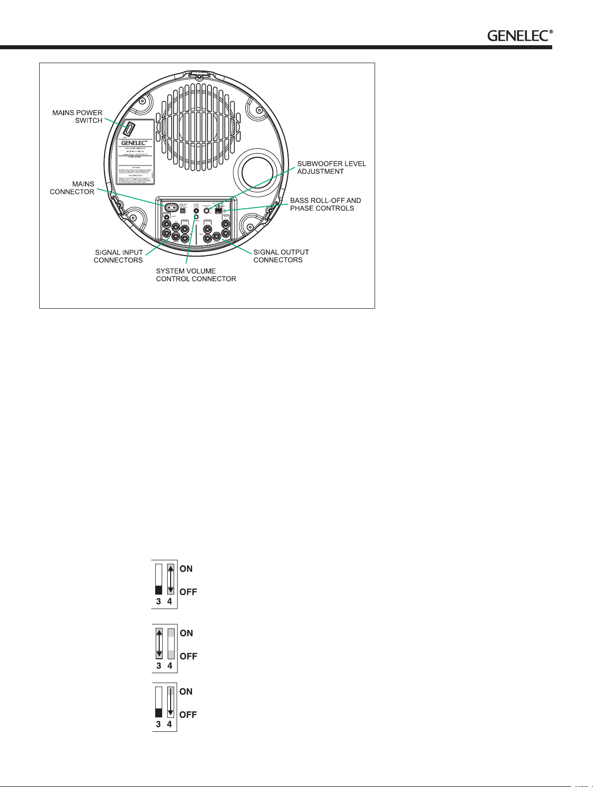
Figure 1. Connectors and controls of the 5040B.
Maintenance
There are no user serviceable parts inside
the subwoofer. Any maintenance of the unit
must only be performed by qualified service
personnel.
Guarantee
This product is supplied with two year guarantee against manufacturing faults or defects that
might alter the performance of the unit. Refer
to supplier for full sales and guarantee terms.
Compliance to FCC rules
This device complies with part 15 of the FCC
Rules. Operation is subject to the following
two conditions:
This device may not cause harmful interference, and This device must accept any interference received, including interference that
may cause undesired operation.
and the subwoofer, the subwoofer should be
placed close to the center of the front loudspeaker array.
Two phase matching switches in the
crossover allow compensation for incorrect
phase alignment. Four settings are provided
between 0° and -270°.
Coarse phase
correction method
Connect an audio frequency signal generator
to a signal input on the subwoofer which has
a main loudspeaker connected to the corresponding “OUT” connector. Set the generator
to 85 Hz. If a signal generator is not available,
then it is possible to use an audio test recording which has a test frequency in the range
70 Hz to 100 Hz. Suitable test signals can be
downloaded at www.genelec.com.
• Togglethe-180°phase
switch ‘ON’ and ‘OFF’ and
set it to the position which
gives the lowest sound level
at the listening position.
• Nexttogglethe-90°phase
switch ‘ON’ and ‘OFF’, and
again set it to the position
which gives the lowest
sound level.
• Finally,setthe-180°phase
switch to the opposite
setting.
Automatic protection circuits
The 5040B is equipped with protection circuits against loudspeaker driver thermal
overload and amplifier overheating. The protection system resets automatically so that
the user only has to turn the input level down
to ensure that it does not reactivate.
Safety considerations
The Genelec 5040B complies with international safety standards. However, to ensure
safe operation and maintain the equipment in
safe operating condition the following warnings and cautions must be observed.
• Servicingandadjustmentmustonlybe
performed by qualified service personnel.
• Openingtheamplierpanelisstrictly
prohibited except by qualified service
personnel.
• Donotexposethesubwoofertowateror
moisture.Donotplaceanyobjectslled
with liquid, such as vases on the
subwoofer or near it.
• Notethattheamplierisnotcompletely
disconnected from the AC mains service
unless the mains cable is removed from
the amplifier or the mains outlet.
Warning!
This equipment is capable of delivering sound
pressure levels in excess of 85 dB, which
may cause permanent hearing damage.
Note: This equipment has been tested and
found to comply with the limits for a Class
B digital device, pursuant to part 15 of the
FCC Rules. These limits are designed to provide reasonable protection against harmful
interference in a residential installation. This
equipment generates, uses and can radiate
radio frequency energy and, if not installed
and used in accordance with the instructions, may cause harmful interference to
radio communications. However, there is no
guarantee that interference will not occur in a
particular installation. If this equipment does
cause harmful interference to radio or television reception, which can be determined by
turning the equipment off and on, the user is
encouraged to try to correct the interference
by one or more of the following measures:
• Reorient or relocate the receiving
antenna.
• Increase the separation between the
equipment and receiver.
• Connect the equipment into an outlet
on a circuit different from that to which the
receiver is connected.
• Consult the dealer or an experienced
radio/TV technician for help.
Modifications not expressly approved by the
manufacturer could void the user’s authority
to operate the equipment under FCC rules.
Page 4
SYSTEM SPECIFICATIONS
5040B
Free field frequency response (± 3 dB) Main 35 Hz...85 Hz
Maximum short term sine wave SPL output
averaged from 40 to 85 Hz, measured in half
space at 1 meter
Self generated noise level in half space at 1 m
on axis (A-weighted)
Driver,magneticallyshielded 165 mm (61/2")
Weight 6.3 kg (13.9 lb)
Dimensions
Height
Diameter
LFE 35 Hz...120 Hz
98 dB
≤ 15 dB SPL
251 mm (97/8”)
305 mm (12”)
CONNECTORS
5040B
Main channels IN/OUT, LFE channel IN unbalanced female RCA connectors
Pin
Ring
Stereo IN 3.5 mm Jack female connector
Sleeve
Tip
Ring
Input impedance 10 kOhm balanced
Main channel OUT gain referred to IN 0 dB
+
gnd
gnd
Left channel
Right channel
AMPLIFIER SECTION
5040B
Amplifier short term output power
(Long term output power is limited by driver
unit protection circuitry)
AmpliersystemTHDatnominaloutput ≤ 0.05 %
Mains voltage Fixed 100, 120 or 230 V
Power consumption (average)
Standby
Idle
Full output
40 W
<0.5 W
7 W
70 W
CROSSOVER SECTION
5040B
Subsonic filter (18 dB/octave) below 35 Hz
Crossover frequency
(subwoofer/main channels)
LFE channel cutoff frequency 120 Hz
Midband rejection >400 Hz >50 dB
Input level for 90 dB SPL output at 1 m -9 dBu at level control max
Sensitivity adjustment range 18 dB
Bass Roll-Off control operating range
in 2 dB steps
Phase matching control in 90° steps From 0 to -270° @ 85 Hz
85 Hz
From 0 to -6 dB @ 35 Hz
Page 5

5040B Aktiivisubwoofer
Yleistä
Genelec 5040B on erittäin kompakti aktiivisubwoofer ja tarkoitettu käytettäväksi
Genelec 6010A/B-aktiivikaiuttimien kanssa
stereo- tai surroundjärjestelmissä ja 8020- ja
8030-aktiivikaiuttimien kanssa stereojärjestelmissä. Koko kaiutinjärjestelmän äänenvoimakkuutta voidaan säätää 5040B:n mukana
toimitettavalla kaukosäätimellä.
Kytkentä
Varmista, että kaikista laitteista on kytketty
virta pois. Euroopassa myytävissä subwoofereissa on kiinteä 230 V jänniteasetus.
Liittimet ja säätimet on sijoitettu subwooferin pohjalevyyn. Käännä laite takaisin normaaliin asentoonsa ennen käyttöä.
Subwooferin otto- ja antoliitännät on tarkoitettu linjatasoiselle signaalille. Subwooferia ei
milloinkaan saa kytkeä vahvistimen passiivikaiuttimille tarkoitettuihin kaiutintasoisiin liitäntöihin. Otto- ja antoliitännät on järjestetty
kahteen rinnakkaiseen ryhmään, ottoliittimet
vasemmalle ja antoliittimet oikealle (kuva 1).
5040B:ssa on kuusi RCA-ottoliitintä
(FRONT L, FRONT R, CENTER, REAR L,
REAR R ja LFE) ja yksi 3.5 mm:n stereojakkiliitin. Näiden avulla 5040B on helppo kytkeä
monenlaisiin äänilähteisiin, esimerkiksi tietokoneen äänikorttiin, MP3-soittimeen, kotiteatterivahvistimen PRE OUT-liittimiin ym.
Kytke äänilähteeltä tulevat signaalikaapelit
subwooferin ottoliittimiin. Kaksikanavainen
signaali voidaan tuoda subwooferiin joko 3.5
mm stereojakin tai FRONT L- ja FRONT RRCA-liittimien kautta. Voit käyttää molempia
liitäntöjä samanaikaisesti kahden äänilähteen
kytkemiseen, mutta joissakin tapauksissa
tämä voi aiheuttaa kohinatason nousemista.
LFE-liitin on tarkoitettu 5.1- tai 2.1-kanavaisen kaiutinjärjestelmän subwooferkanavan kytkemiseen, CENTER keskikanavalle ja
REAR L ja R takakanaville.
Oikeanpuoleisessa ryhmässä ovat pääkanavien antoliittimet (OUT). Kytke pääkaiuttimille lähtevät signaalijohdot näihin liittimiin.
Genelec 8020- ja 8030-aktiivikaiuttimien
ottoliitin on XLR-tyyppinen, joten jos käytät
5040B-subwooferia 8020- tai 8030-parin
kanssa, tarvitset signaalijohdot, joiden toisessa päässä on RCA-liitin ja toisessa XLR.
Tällaisia johtoja on saatavissa Genelecin
jälleenmyyjiltä ja johdon kytkentä on esitetty kaiuttimien käyttöohjeessa. Käytettäessä 8020:ta tai 8030:a 5040B-subwooferin
kanssa kaiuttimien Bass Roll-Off-kytkin tulee
olla asennossa ”OFF”
5040B-subwoofer on varustettu jakosuotimella, joka suodattaa kaikkien viiden pääkanavan signaaleista alle 85 hertsin taajuudet
subwooferin toistettaviksi, ja ohjaa korkeammat antoliitäntöjen kautta pääkaiuttimille. Näin
subwoofer ottaa kantaakseen osan pääkaiuttimien bassokuormasta. Kun pääkanavat on
kytketty tällä tavoin subwooferin kautta, tulee
surround-dekooderin kaiutinasetuksissa käyttää asetusta ”suuri” (Large) kaikille pääkaiuttimille.
5040B:n LFE-kanavan ylärajataajuus on
120 Hz, mikä on yhteensopiva yleisimpien
tallennusformaattien kanssa.
Kytke kaukosäätimen johto “SYSTEM
VOLUME CONTROL”-liittimeen. Kaukosäädin säätää koko järjestelmän äänenvoimakkuutta. Kaukosäädin voidaan jättää myös
kytkemättä, jos äänilähteessä on sopiva
äänenvoimakkuuden säätö. Kytke viimeiseksi
subwooferin virtajohto ja laita virta päälle.
Subwooferin sijoitus
Bassotoiston taso ja tasapaino riippuu suuressa määrin bassotaajuuksia tuottavan kaiuttimen sijainnista huoneessa. Suhteellisen
pienikin siirtäminen voi aiheuttaa merkittävän
muutoksen sointitasapainoon. Subwooferin oikean paikan etsimiseen kannattaakin
paneutua kärsivällisesti ja huolellisesti ja
jättää herkkyys- vaiheenkääntö- ja basson
tason säädöt alkuasetuksiinsa, kunnes akustisesti edullisin sijoitus on löydetty. Sen jälkeen niitä voidaan käyttää toiston lopulliseen
hienosäätöön.
Hyvä sijoitus löytyy usein etukaiuttimien
takana olevalta seinältä, hieman sivussa huoneen keskilinjalta. Subwoofer kannattaa pitää
lähellä seinää, alle 60 cm:n etäisyydellä. Tällöin subwoofer toimii neljännesavaruudessa
(kahden rajapinnan risteyksessä), mikä tukee
sen bassotoistoa ja eliminoi haitalliset heijastukset etuseinästä ja lattiasta. Etukaiuttimien
takana oleva seinä voi aiheuttaa äänenlaatua
heikentäviä heijastuksia, jolloin kaiuttimesta
taaksepäin säteilevät ääniaallot kimpoavat
seinästä ja summautuvat viivästyneinä kaiuttimesta kuuntelupaikalle suuntautuvaan
ääneen. Tämä ongelma voidaan minimoida
käytettäessä subwooferin sisäistä 85 hertsin
jakosuodatusta ja siirtämällä etukaiuttimet
vähintään 110 cm:n etäisyydelle seinästä.
Ellei bassotoisto ole tasapainossa, siirrä
subwooferia vasemmalle tai oikealle. Nurkkaan sijoittaminen korostaa bassotaajuuksia
voimakkaasti ja saattaa vääristää akustista
tilavaikutelmaa.
Vaikkakin Genelec 5040B-subwooferin
kaiutinelementti on magneettisuojattu, se voi
lähelle sijoitettuina aiheuttaa värin tai geometrian vääristymiä herkissä kuvaputkissa.
Häiriöitä voidaan lieventää siirtämällä subwoofer kauemmaksi.
Automaattinen virrankytkentä
(ISSTM Autostart)
Subwooferissa on signaalin tunnistava
automaattinen virrankytkentä, joka kytkee
sen toimintaan heti kun subwooferiin tulee
äänisignaali. Vastaavasti subwoofer menee
automaattisesti valmiustilaan, kun signaalin
päättymisestä on kulunut tunti. Valmiustilassa
kaiuttimien tehonkulutus on alle 0,5 W.
Subwooferin
äänenvoimakkuuden
perussäätö
Subwooferin ja pääkaiuttimien äänenvoimakkuuserojen tasoittamiseksi 5040B on varustettu äänenvoimakkuuden perussäädöllä.
Säädin (SUBWOOFER LEVEL) on subwooferin pohjalevyssä. Subwooferin äänen voimakkuus lisääntyy säädintä myötäpäivään
kiertämällä ja vähenee säädintä vastapäivään kiertämällä.
Vakioasetus säädölle on -6 dB maksimitasosta (kello 9), mikä on yleensä sopiva lähtötaso sovitettaessa subwooferia 6010-kaiuttimiin. Jos subwooferia käytetään 8020- tai
8030-mallien kanssa, tulee pääkaiuttimien
äänenvoimakkuutta alentaa kääntämällä
edessä oleva kierrettävää säädintä vastapäivääan
Basson tason säätimet
Subwooferin alimpien taajuuksien toistoa
voidaan muokata vastaamaan kulloistakin akustista ympäristöä basson säätimillä
(BASS ROLL-OFF). Pohjalevyssä olevilla
kytkimillä voidaan vaimentaa bassotoistoa.
Page 6

Kuva 1. 5040B:n liitännät ja säätimet.
Vasemmanpuoleinen kytkin vaimentaa toistoa -4 dB, oikeanpuoleinen -2 dB. Maksimivaimennus saadaan, kun molemmat kytkimet käännetään asentoon ”ON”.
Vaiheen säätö
Subwooferin ja pääkaiuttimien virheellinen
vaiheistus aiheuttaa vaimentuman niiden
väliselle jakotaajuudelle 5040B on varustettu
neliportaisella 0°...-270° asteen vaiheensäädöllä, jolla tätä virhettä vidaan korjata. Vaiheero riippuu subwooferin ja pääkaiuttimien
keskinäisestä sijainnista, joten sitä kannattaa
lähteä korjaamaan vasta kun kaiuttimet ovat
lopullisilla sijoituspaikoillaan.
Vaiheen säätö
testisignaalin avulla
Valitse dekooderin kaiutinasetuksista etukaiuttimet ”pieniksi” (small).
Kytke subwoofer ja vain yksi pääkaiuttimista päälle ja soita 85 hertsin pistetaajuutta.
Sopivan 85 hertsin signaalin voit löytää
Genelecin kotisivun Tuotetuki-osiosta, audiolaitteiden säätöön tarkoitetuilta testilevyiltä tai
tuottaa sopivalla signaaligeneraattorilla.
Käännä -180° vaihekytkin
vuoroin päälle ja pois, ja
jätä se siihen asentoon, jolla
bassotoisto kuuntelupaikalla on
vaimeampi.
Tee samoin -90° vaihekytkimelle.
Lopuksi käännä -180° vaihekytkin vastakkaiseen asentoonsa.
Automaattinen
ylikuormitussuojaus
5040B-subwoofer on varustettu automaattisella ylikuormitussuojauksella elementin
puhekelan ja vahvistimen ylikuumenemisen
varalta. Jos suojaus kytkeytyy, alenna äänenvoimakkuutta.
Turvallisuusohjeita
Genelec 5040B-subwoofer on suunniteltu ja
valmistettu täyttämään kansainväliset turvallisuusnormit. Virheellisestä käytöstä saattaa
kuitenkin seurata vaaratilanne, joten seuraavia ohjeita on aina noudatettava:
•Laitetta ei saa asettaa alttiiksi
kosteudelle tai roiskevedelle. Se on
tarkoitettu käytettäväksi ainoastaan
kuivassa huonetilassa.
•Huolto- ja korjaustoimia saa
suorittaa vain valmistajan valtuuttama
huoltohenkilöstö.
•Älä avaa koteloa tai irrota
laitteesta mitään osia.
•Huomaa, että vahvistin ei ole täysin
jännitteetön ellei virtajohtoa ole irrotettu
pistokkeesta.
VAROITUS!
Genelec 5040B pystyy tuottamaan yli 85
desibelin äänenpaineen, mikä voi aiheuttaa
pysyvän kuulovaurion.
Huolto
Kaikki huolto- ja korjaustoimet on annettava
valmistajan tai valmistajan valtuuttaman
huoltohenkilöstön suoritettaviksi. Älä avaa
laitetta itse.
Takuu
Genelec Oy antaa tuotteilleen ostopäivästä
lukien kahden vuoden takuun. Takuu kattaa
valmistusvirheet ja materiaaliviat.
Page 7

TEKNISET TIEDOT
5040B
Taajuusvaste vapaakentässä (± 3 dB) Pääkanavat 35 Hz...85 Hz
Hetkellinen maksimiäänenpaine mitattuna
sinisignaalilla puoliavaruuteen
(keskiarvo 40...85 Hz 1 m etäisyydellä)
Akustinen pohjakohinataso (A-painotettu) 1 m
etäisyydellä
Kaiutinelementti (magneettisuojattu) 165 mm (61/2")
Paino 6,3 kg
Mitat
Korkeus
Halkaisija
LFE 35 Hz...120 Hz
98 dB
≤ 15 dB SPL
251 mm
305 mm
LIITÄNNÄT
5040B
RCA-ottoliitäntöjä
RCA-antoliitäntöjä
3.5 mm stereojakkiliitin 1 kpl
Ottoimpedanssi 10 kOhm
Antoliitäntöjen taso 0 dB
6 kpl (5+LFE)
5 kpl
VAHVISTIN
5040B
Vahvistimen lyhytkestoinen teho (kaiutinelementin suojauselektroniikka
rajoittaa vahvistimen jatkuvaa tehoa)
Vahvistimensärönimellisteholla(THD) ≤ 0.05 %
Verkkojännite 230 V
Tehonkulutus keskimäärin
Valmiustila
Min
Max
40 W
<0,5 W
7 W
70 W
JAKOSUODIN
5040B
Ylipäästösuodin (18 dB/oktaavi) <35 Hz
Jakotaajuus subwoofer/pääkanavat 85 Hz
LFE-kanavan ylärajataajuus 120 Hz
Vaimennus >400 Hz >50 dB
Bass Roll-Off-säätö 2 dB:n portain 0 ... -6 dB @ 35 Hz
Vaiheen säätö 90 asteen välein 0 ... -270° @ 85 Hz
Page 8

Caisson grave 5040B
Descriptiongénérale
Le Genelec 5040B est un caisson grave
actif très compact, conçu pour accompagner
jusqu’à cinq enceintes actives Genelec 6010
ou une paire des plus grandes 8020’s. Le
5040B étends la reproduction des basses
du système jusqu’à 35 Hz et s’intègre parfaitement avec les 6010 dans tous les environements. Le réglage du volume sonore du
système complet est commodément controllé
par la commande à distance de volume fournit avec le caisson grave.
Installation
Assurez-vous que tous les appareils soient
éteints avant d’effectuer toutes connexions
audio.
Le caisson grave est équipé de six
connecteurs d’entrée de type RCA (FRONT
L, FRONT R, CENTER, REAR L, REAR R
et LFE) ainsi qu’un connecteur jack 3.5 mm
stéréo. Cette connectique permet au 5040B
d’être branché à une multitude de sources
audio de niveau ligne qui possèdent soit
des connecteurs jack 3.5 mm stéréo soit
des connecteurs RCA.
peuvent être des préamplificateurs, des cartes
son, des lecteurs audio portables, les sorties
“PRE OUT” d’un décodeur Home Cinema, etc.
Attention de ne pas utiliser en même temps
les entrées Jack 3.5 mm et les entrées RCA
avant gauche et droite (FRONT L et R).
Comme le 5040B contient son propre
amplificateur, aucun autre amplificateur
de puissance séparé n’est nécessaire. Ne
jamais connecter le 5040B aux sorties hautparleurs d’un amplificateur de puissance,
d’un amplificateur intégré ou d’un amplificateur/récepteur.
Branchez les câbles de signal provenant de
la source aux connecteurs RCA correspondants. Ensuite, raccordez les enceintes principales 6010 au caisson grave avec des câbles
RCA depuis les connecteurs du caisson grave
FRONT L, FRONT R, CENTER, REAR L et
REAR R “OUT” aux connecteurs d’entrée des
enceintes principales correspondantes.
Le 5040B contient un répartiteur de fréquence actif pour les cinq canaux principaux
qui dirige les fréquences en dessous de 85
Hz vers le caisson grave et les fréquences
au-dessus vers les enceintes principales via
les connecteurs de sortie. Lors de l’utilisation
d’un décodeur Home Cinema, la sélection
Ces sources audio
“Large” pour les haut-parleurs principaux est
recommandée pour tous les canaux connectés au caisson grave.
Le canal
décodeur peut être connecté à l’entrée “LFE
IN” du caisson grave. Le canal LFE branché
au 5040B peut être reproduit jusqu’à 120 Hz.
Branchez la commande à distance de
volume au connecteur “SYSTEM VOLUME
CONTROL”. La commande à distance règle le
niveau du volume sonore du caisson grave et
de toutes les enceintes principales connectées.
Une fois toutes les connexions effectuées,
le caisson grave et les enceintes principales
peuvent être mis sous tension.
LFE du préamplificateur ou du
Positionnement dans une pièce
L’emplacement du caisson grave dans une
pièce a une très grande influence sur la
réponse en fréquence et le niveau sonore
global, car à basses fréquences, les effets
de la pièce sont importants. Même le plus
petit déplacement du caisson grave peut
modifier considérablement l’équilibre des fréquences, et il est souvent nécessaire de faire
des essais et des tests méthodiques, avec
patience, afin de trouver l’endroit idéal.
La position du caisson aura un effet sur la
différence de phase entre les enceintes principales et le caisson grave ainsi que sur l’extension de la réponse dans les graves. Ces
effets peuvent être compensés et ajustés en
utilisant les contrôles du caisson grave, mais
dans un premier temps nous vous recommandons de ne pas utiliser ces contrôles et
de trouver une position ou le caisson grave
produit un son équilibré et ensuite seulement
d’utiliser les contrôles pour régler de manière
fine l’équilibre et la phase entre le caisson
grave et les enceintes principales.
Tout d’abord, placez le caisson grave au
centre et contre le mur frontal. Nous recommandons une distance de moins de 60 cm /
24 po entre le transducteur du caisson et le
mur. Cette position accroît la charge acoustique (et le niveau de pression acoustique) du
fait de la proximité du mur frontal et du sol.
Les annulations de phase par rapport au mur
frontal et au sol sont ainsi également évitées.
Idéalement, le caisson grave et les enceintes
principales devraient être placés de manière
symétrique et à égale distance de la position
d’écoute.
Si l’équilibre des fréquences semble incorrect, essayez de déplacer le caisson grave
légèrement vers la gauche ou vers la droite
de sorte que les différents modes de la pièce
soient activés à des niveaux différents. Placer
le caisson grave à proximité d’un coin amplifiera le niveau des graves à de plus basses
fréquences et pourrait aussi générer une
image sonore asymétrique.
Bien que le 5040B soit magnétiquement
blindé, il peut causer une distorsion des couleurs s’il est placé à côté de moniteurs vidéo
ou d’écrans très sensibles.
ISSTM Allumage automatique
L’caisson grave se met sous tension dès détection de la présence d’un signal audio. A
l’opposé, l’caisson grave se mettra automatiquement en mode veille après une heure
d’absence de signal audio. La consommation électrique de l’caisson grave en mode
veille est inférieure à 0,5 watts. L’caisson
grave s’allumera à nouveau automatiquement et rapidement dès la détection d’un
retour de signal audio depuis la source.
Réglage du volume du
caisson grave
Le contrôle de volume du caisson grave est
situé sur le panneau de connexion du caisson. Le réglage d’usine est -6 dB (position
9 heures) en-dessous du maximum, ce qui
donne un bon point de départ pour le réglage
de la balance du volume avec les enceintes
6010. Lors de l’utilisation du 5040B avec
les enceintes Genelec 8020, le niveau des
enceintes principales doit typiquement être
baissé en tournant le réglage de volume sur
la face frontale des 8020 de la position maximale à une position vers 12 heures.
Réglage des commutateurs
Bass Roll-Off
Il est possible que la réponse acoustique du
caisson doive être réglée selon les caractéristiques de la pièce et le positionnement de ce
dernier. Pour réaliser ce réglage, vous devez
utiliser les commutateurs ‘BASS ROLL-OFF’
situés sur le panneau de connexion. Lorsque
tous les commutateurs Roll-Off sont ‘OFF’,
on obtient une réponse linéaire en chambre
anéchoïque.
Réglage du contrôle de phase
Un mauvais réglage de phase entre les
enceintes principales et le caisson grave
Page 9

Figure 1. Connecteurs et contrôles du 5040B.
entraîne une diminution de la réponse en
fréquence de tout le système à la fréquence
de coupure enceintes/caisson. La différence
de phase entre les enceintes principales et
le caisson grave au point d’écoute dépend
de l’emplacement du caisson. Pour éviter
une différence de phase entre les enceintes
gauche et droite et le caisson, celui-ci devrait
être placé près du centre de la configuration
des enceintes frontales.
Deux commutateurs de phase à la fréquence de coupure sont disponibles pour
compenser un alignement de phase incorrect.
Quatres positions sont disponibles entre 0° et
-270°.
Méthode de réglage grossier
de phase
Raccordez un générateur de signal de fréquence audio à une entrée du caisson grave qui
a une enceinte principale raccordée au connecteur “OUT” correspondant. Réglez le générateur pour qu’il fournisse un signal à 85 Hz. Si un
générateur n’est pas disponible, vous pouvez
également utiliser un signal entre 70 Hz et 100
Hz provenant d’un enregistrement de signaux
detestdebonnequalité. Diverssignauxde
tests sont disponibles à www.genelec.com.
• Basculezlecommutateur
de -180°, sélectionnez ‘ON’
et ‘OFF’, et laissez le dans
la position qui produit le
niveau sonore le plus bas
au point d’écoute.
• Ensuite,basculezle
commutateur -90°,
sélectionnez ‘ON’ et ‘OFF’,
et à nouveau, laissez le
dans la position qui produit
le niveau sonore le plus bas.
• Enn,placezle
commutateur de -180°
en position inverse.
Circuits de protection
automatique
Le 5040B est équipé de circuits de protection automatique contre les surchauffes
des transducteurs et des amplificateurs. Le
système de protection se remet en marche
automatiquement et l’utilisateur a seulement
besoin de réduire le niveau d’entrée pour
éviter la réactivation du système de protection.
Considérations liées
à la sécurité
Le Genelec 5040B est conforme au normes
de sécurité internationales. Toutefois, afin
d’assurer un fonctionnement sûr et conserver
l’unité dans un état de marche sécuritaire,
veuillez observer les remarques et avertissements suivants :
• L’entretienetleréglageducaisson
grave doivent uniquement être effectués
par un service technique qualifié.
• Nepasouvrirl’unitéd’amplicationdu
caisson grave, exception faite par un
service technique qualifié.
• Nepasexposerlecaissongraveàl’eau
ou à l’humidité. Ne poser aucun objet
rempli de liquide, tel qu’un vase, sur le
caisson grave ou à proximité.
• Remarquezquel’amplicateurn’est
totalement déconnecté de l’alimentation
secteur que lorsque le cordon
d’alimentation est débranché de
l’amplificateur ou de la prise de courant.
Avertissement!
Ce caisson grave peut fournir des niveaux de
pression acoustique supérieurs à 85 dB, ce qui
peut entraîner une lésion auditive permanente.
Entretien
Le caisson grave ne comporte aucune pièce
pouvant être réparée par l’utilisateur. Toute
opération de maintenance sur l’unité doit être
effectuée par un personnel technique qualifié.
Garantie
Ce produit est livré avec deux ans de garantie contre les défauts de fabrication qui pourraient altérer sa performance. Consultez
votre fournisseur pour obtenir les conditions
de vente et de garantie dans leur intégralité.
Page 10

SPÉCIFICATIONS DU CAISSON
5040B
Réponse en fréquence en champ libre
(± 3 dB)
Pression maximale à court terme avec signal
sinusoïdal, moyenne de 40 à 85 Hz, mesurée
en demi-espace à 1 mètre
Niveau du bruit de fond en demi-espace à 1 m
dans l’axe (pondération A)
Transducteur, blindage magnétique 165 mm (61/2")
Poids 6.3 kg (13.9 lb)
Dimensions
Hauteur
Diamètre
Principaux 35 Hz...85 Hz
LFE 35 Hz...120 Hz
98 dB
≤ 15 dB SPL
251 mm (97/8”)
305 mm (12”)
CONNECTEURS
5040B
Canaux principaux IN/OUT, canal LFE IN,
connecteurs RCA femelles asymétriques
Pin (broche)
Ring (anneau)
Stéréo IN, connecteur femelle Jack 3.5 mm
Sleeve (manchon)
Tip (pointe)
Ring (anneau)
Impédance d’entrée 10 kOhm symétrique
Gain de sortie (OUT) des canaux principaux
réferré à l’entrée (IN)
+
terre
terre
Canal gauche
Canal droit
0 dB
SECTION AMPLIFICATION
5040B
Puissance de sortie à court terme de
l’amplificateur (la puissance de sortie à long
terme est limitée par le circuit de protection du
haut-parleur)
Distorsiondusystèmed’amplicationen
niveaunominalDHT
Voltage d’alimentation 100, 120 ou 230 V
Consommation (moyenne)
En veille
En attente de signal
Sortie maximale
40 W
≤ 0.05 %
<0,5 W
7 W
70 W
SECTION FILTRES
5040B
Filtre subsonique (18 dB/octave) en dessous de35 Hz
Fréquence de coupure
(caisson grave/enceintes principales)
Fréquence de coupure du canal LFE 120 Hz
Rejection (fréquences moyennes) >400 Hz >50 dB
Plage de réglage de la sensibilité -9 dBu pour 90 dB SPL
Plage de réglage du contrôle Bass Roll-Off
par incréments de 2 dB
Contrôle d’ajustement de phase par incréments de 90°
85 Hz
De0à-6dB@35Hz
De0à-270°@85Hz
Page 11

Page 12

5040B
Genelec 5040B
Active Subwoofer
GenelecDocumentD0078R003.CopyrightGenelecOy3.2013.
International enquiries:
Genelec, Olvitie 5
FIN-74100, Iisalmi, Finland
Phone +358 17 83881
Fax +358 17 812 267
Email genelec@genelec.com
In the U.S. please contact:
Genelec Inc., 7 Tech Circle
Natick, MA 01760, U.S.A.
Phone +1 508 652 0900
Fax +1 508 652 0909
Email genelec.usa@genelec.com
In China please contact:
Beijing Genelec Audio Co. Ltd.
Jianwai SOHO, Tower 12, Room 2605
39East3rdRingRoad,ChaoyangDistrict
Beijing 100022, China
Phone +86 10 5869 7915
Fax +86 10 5869 7914
www.genelec.com
In Sweden please contact
Genelec Sverige
Ellipsvägen 10B
P.O. Box 5521, S-141 05 Huddinge
Phone +46 8 449 5220
Fax +46 8 708 7071
Email info@genelec.com
 Loading...