

Page 1
4040A
Operating Manual
Genelec 4040A
Active Loudspeaker
Page 2
General
Controls
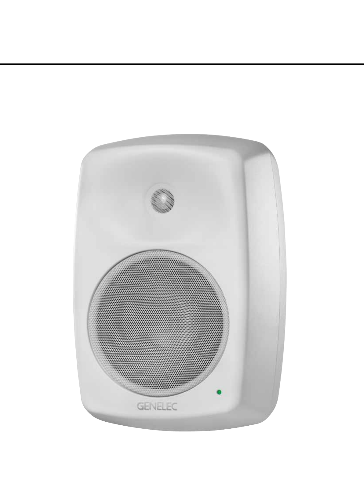
The bi-amplified Genelec 4040A is a powerful but compact two way active loudspeaker
designed for fixed installations. As an active
loudspeaker, it contains drivers, power amplifiers, active crossover filters and protection
circuitry. The 4040A is designed for indoor
use only, in temperatures between 15 to
35 degrees Celsius and relative humidity
between 20 % and 90 %.
The MDE™ (Minimum Diffraction Enclosure™) loudspeaker enclosure is made
of die-cast aluminium and shaped to
reduce edge diffraction. Combined with the
advanced Directivity Control Waveguide
TM
(DCW
), this design provides excellent frequency balance in difficult acoustic environments.
TM
Positioning The Loudspeaker
Each 4040A is supplied with an integrated
amplifier unit, mains cable, a 5-pin connector for audio signal and 12 V trigger voltage,
a keyhole type wallmount and an operating
manual. After unpacking, place the loudspeaker in its required listening position,
taking note of the line of the acoustic axis.
The axis should be pointed towards the
center of the listening area.
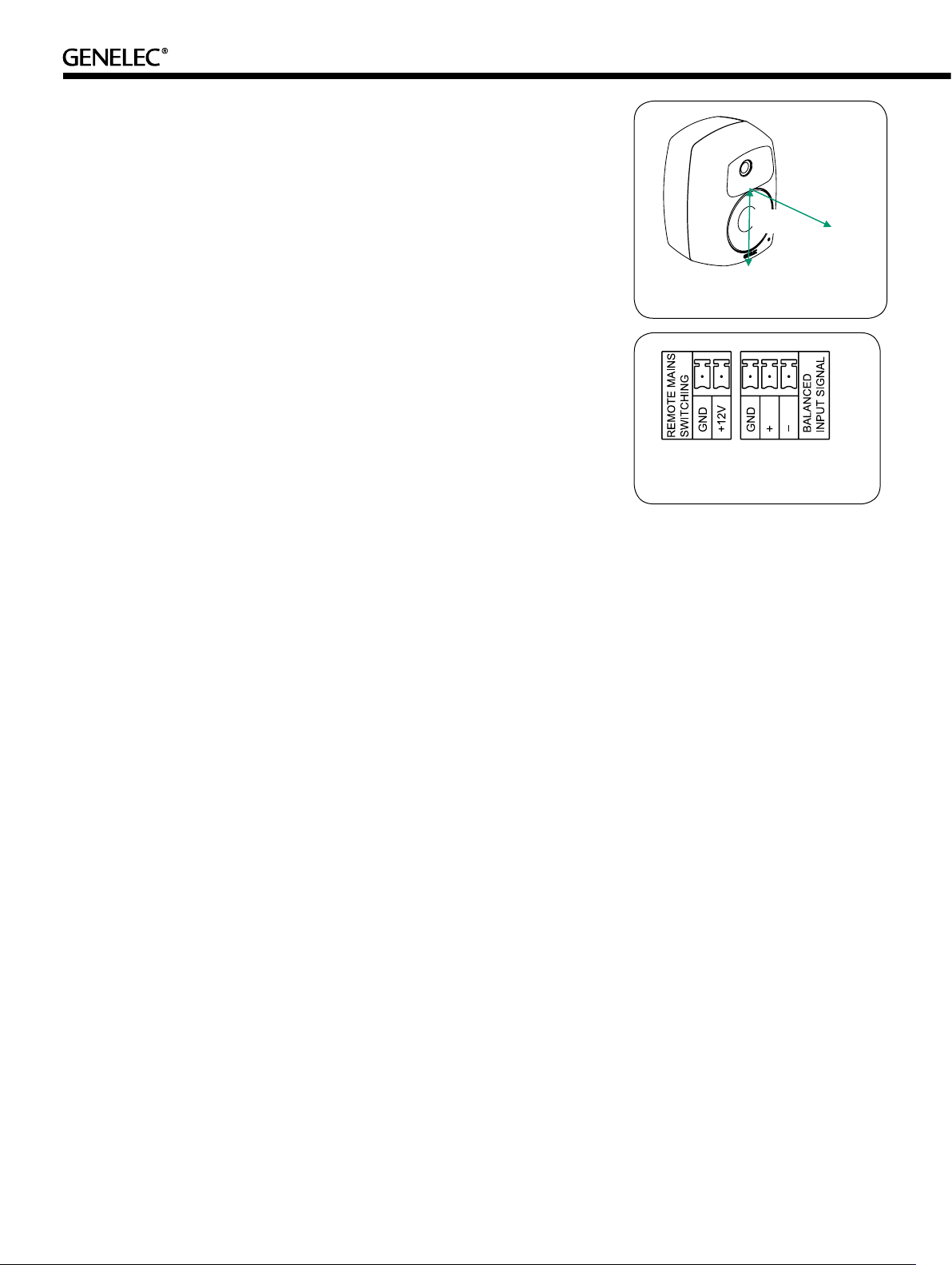
Connections
Before connecting up, ensure that the loudspeakers and the signal source have been
switched off. The power switch of the 4040A
is located on the back panel (see Figure
3). Connect the loudspeaker to an earthed
mains connection with the supplied mains
cable. Never connect the loudspeaker to
an unearthed mains supply or using an
unearthed mains cable. Audio input is via
a 10 kOhm balanced Phoenix connector. The connector also has two pins for 12
V trigger voltage for power switching. The
pin sequence of the connector is shown in
Figure 2.
Connect the signal cable and 12 V trigger
voltage to the 5-pole plug provided with the
loudspeaker and secure the connections by
tightening the screws on each pole. Push the
plug into the connector on the loudspeaker.
Never connect the 4040A to the loudspeaker outputs of a power amplifier or an
integrated amplifier or receiver.
Once the connections have been made,
the loudspeaker is ready to be switched on.
Level Control
The input sensitivity of the loudspeaker can
be matched to the output of the signal source
by adjusting the rotary level control on the
rear panel.
Autostart Sensitivity
This control sets the triggering sensitivity of
the signal sensing Autostart function. In case
of a high background noise level in the audio
network, the automatic shutoff may not function as the circuit detects the noise and misinterprets it as a valid signal. Switching the
“Autostart Sensitivity” switch to “ON” reduces
the triggering sensitivity and gives better
immunity to noise in the signal network. On
the other hand, if a very low playback level
is desirable, the Autostart function works
better in the more sensitive “OFF” setting.
The required triggering voltages are approximately 0.4 mV (OFF) and 1.4 mV (ON).
Autostart Off Time
This control sets the shutoff delay of the
Autostart function. When the switch is set to
“OFF”, the loudspeaker shuts off one hour
after ending the playback. In the “ON” setting,
the delay is 15 minutes.
Led Off
This switch turns off the green power indicator LED. However, the overload indication by
red coloured LED remains active.
Tone Controls
The frequency response of the Genelec
4040A can be adjusted to match the acoustic environment by setting the tone control
switches on the rear panel. The controls
are “Bass Roll-Off”, “Bass Tilt” and “Treble
Tilt”. An acoustic measuring system is recommended for analyzing the effects of the
adjustments, however, careful listening with
suitable test recordings can also lead to good
results if a test system is not available. Table
1 shows some examples of typical settings in
various situations. Figure 4 shows the effect
of the controls on the anechoic frequency
response.
Bass Roll-Off
The Bass Roll-Off control (switches 1 to 3
in switch group 1) affects the low frequency
roll-off of the loudspeaker and attenuates its
ACOUSTIC
AXIS
225mm
8 7/8”
Figure 1: Location of the acoustic axis
Figure 2: Audio and 12 V trigger
connector pin sequence
energy output near the cut-off frequency (55
Hz). Attenuation levels of -2, -4 or -6 dB can
be selected.
Bass Tilt
The Bass Tilt control (switches 2 to 4 in
switch group 2) offers three attenuation levels
for the bass response of the loudspeaker
below 800 Hz, usually necessary when the
loudspeaker is placed near a wall or other
room boundaries. The attenuation levels are
-2 dB (switch 3 “ON”), -4 dB (switch 4 “ON”)
and -6 dB (both switches “ON”).
Treble Tilt
The Treble Tilt control (switches 2 to 4 in
switch group 3) adjusts the treble response
of the loudspeaker at frequencies above 4
kHz. Two attenuation levels, -2 dB (switch 3
“ON”) or -4 dB (switch 2 “ON”) are available
for smoothening down an excessively bright
sounding system, while the +2 dB setting
(switch 4 “ON”) provides slightly increased
treble level suitable for heavily damped surroundings.
The factory setting for all tone controls is
“OFF” to give a flat anechoic frequency
response. Always start adjustment by setting all switches to “OFF” position. Measure
or listen systematically through the different
combinations of settings to find the best frequency balance.
Page 3

BRACKET INSTALLED
WALL MOUNT
MAINS CONNECTOR
MAINS POWER
SWITCH
SUGGESTEDTONECONTROL SETTINGS
3
4213421
-6dBBASS
-4dBBASS
TILT
TILT
FREESTANDINGIN AROOM:
ALLTONECONTROLSOFF
MAINSINPUT
50/60Hz170W230V~
SERIALNUMBER
-6
-4
BASS
ROLLOFFdB
-2
AUTOSTART
SENSITIVITY
OFFON
4040AACTIVE
SPEAKERSYSTEM
MADEIN FINLAND
The triggering sensitivity can be selected
with the Autostart Sensitivity switch (see
chapter Autostart Sensitivity above).
The amplifier mode can also be switched
by a 12 V DC trigger type remote control. The
remote control wires can be connected to the
first two (starting from left) poles of the Phoe-
CONTROL
SWITCHES
-2
+2
-4
-2
-6
-4
BASS
TREBLE
TILTdB
TILTdB
TIME
LEDOFF
AUTOOFF
MAX
MIN
LEVEL
_
GND
GND
+12V
+
BALANCED
INPUTSIGNAL
SWITCHING
REMOTEMAINS
www.genelec.com
292-4040T-6
SENSITIVITY
ADJUSTMENT
BALANCED SIGNAL
INPUT CONNECTOR
AND 12 V TRIGGER INPUT
nix connector (See Figure 2 for the connector
pin sequence). Remote control overrides the
Autostart function.
Maintenance
No user serviceable parts are to be found
within the loudspeaker. Any maintenance
or repair of the 4040A unit should only be
undertaken by qualified service personnel.
Figure 3: Control and connector layout on the rear panel of an 4040A.
Speaker Mounting Position Treble Tilt Bass Tilt Bass Roll-Off
Flat anechoic response None None None
Free standing in a damped room None -2 dB None
Free standing in a reverberant room None -4 dB None
In a corner None -4 dB -4 dB
Table 1: Suggested tone control settings for differing acoustical environments
Mounting Considerations
adjacent to the amplifier (back panel of the
enclosure) must either be ventilated or suf-
Align The Loudspeakers Correctly
Always place the loudspeakers so that their
acoustic axes (see Figure 1) are aimed
ficiently large to dissipate heat so that the
ambient temperature does not rise above 35
degrees Celsius (95°F).
towards the center of the listening area.
Only vertical placement is preferred, as it
minimises acoustical cancellation problems
around the crossover frequency.
The Genelec 4040A offers several mount-
ing options: It can be fitted to Omnimount®
Mounting Options
Series 30 and König & Meyer loudspeaker
Minimise Reflections
Acoustic reflections from objects close to the
loudspeakers like walls, cabinets etc. can
cause unwanted colouration or blurring of
the sound image. These can be minimised
by placing the loudspeaker clear of reflective
surfaces.
mounts or the keyhole wall mount adapter
provided with the loudspeaker on two sets
of M6x10 mm threaded holes on the back of
the enclosure. On the base of the enclosure
is an M10x10 mm threaded hole which can
be used for securing the loudspeaker to its
base. See Genelec Accessories Catalogue
on www.genelec.com for a complete list of
Minimum Clearances
mounting hardware options.
Sufficient clearance for cooling of the amplifier and functioning of the reflex port must be
ensured if the loudspeaker is installed in a
restricted space such as a cabinet or integrated into a wall structure. The surroundings
of the loudspeaker must always be open to
the listening room with a minimum clearance
of 5 centimeters (2”) behind, above and on
both sides of the loudspeaker. The space
Autostart And Remote Control
The 4040A is equipped with an Autostart
function, which automatically turns the ampli-
fier to Standby mode if an input signal has
not been detected for approximately 3 hours
(Auto Off Time switch set to “OFF”) or 15 min-
utes (Auto Off Time switch set to “ON”), and
back to “ON” mode when the signal returns.
Safety Considerations
Although the 4040A has been designed in
accordance with international safety standards, the following warnings and cautions
should be observed to ensure safe operation
and to maintain the loudspeaker under safe
operating conditions:
•Servicing and adjustment must only be
performed by qualified service personnel.
•The loudspeaker must not be opened.
•Do not use this product with an
unearthed mains cable or an unearthed
mains connection as this may compromise electrical safety.
•Do not expose the loudspeaker to water
or moisture. Do not place any objects
filled with liquid, such as vases on the
loudspeaker or near it.
•This loudspeaker is capable of producing sound pressure levels in excess of
85dB, which may cause permanent hearing damage.
•Free flow of air behind the loudspeaker
is necessary to maintain sufficient cooling. Do not obstruct airflow around the
loudspeaker.
•Note that the amplifier is not completely
disconnected from the AC mains service
unless the mains power cord is removed
from the amplifier or the mains outlet.
Guarantee
This product is guaranteed for a period of two
years against faults in materials or workmanship. Refer to supplier for full sales and guarantee terms.
Page 4

4040A Operating Manual
Genelec Oy 4040A (dBr) vs freq (Hz) 31 Jul 12
80
85
90
75
BASS ROLL-OFF
TREBLE TILT
BASS TILT
Genelec Oy 4040A (dBr) vs freq (Hz) 31 Jul 12
65
70
75
60
0° 15° 30°
45° 60°
90
d
B
85
r
80
A
100
200
50
30
500
1k 2k
Figure 4: The effect of the tone controls to the free field response of
the 4040A.
4040A
Lower cut-off frequency, -3 dB
Upper cut-off frequency, -3 dB
Free field frequency response of system
55 Hz
≤
≥
20 kHz
55 Hz - 20 kHz
(± 3.0 dB)
Maximum short term sine wave acoustic output
≥
109 dB SPL
on axis in half space, averaged from 100 Hz to
3 kHz@ 1 m
Maximum long term RMS acoustic output in
≥
101 dB SPL
same conditions with IEC weighted noise
(limited by driver unit protection circuit) @ 1 m
Self generated noise level in free field @ 1m on
≤ 10 dB
axis (A-weighted)
Harmonic distortion at 90 dB SPL
@ 1m on axis
Freq. 50 to 100 Hz
> 100 Hz
Drivers:
Bass
Treble
< 3 %
< 0.5 %
165 mm (6 1/2")
19 mm (3/4") metal
dome
Weight: 9.9 kg (22 lbs)
Dimensions:
Height
Width
Depth
350 mm (13 13/16“)
237 mm (9 3/8“)
223 mm (8 13/16“)
90
d
B
85
r
80
A
100
200
10k
20k
Hz
5k
50
30
500
1k 2k
5k
10k
20k
Hz
Figure 5: The upper curve group shows the horizontal directivity
characteristics of the 4040A measured at 1 m. The lower curve shows
the system’s power response.
CROSSOVER SECTIONSYSTEM SPECIFICATIONS
4040A
Input connector Balanced Phoenix connector Pin 1 gnd, pin 2 +, pin 3 -
Input impedance 10 kOhm balanced
Input level for maximum short term output of
100 dB SPL @ 1m:
Adjustable from +6 to
-6 dBu
Crossover frequency, Bass/Treble 2.5 kHz
Treble tilt control operating range in 2 dB steps From +2 to -4 dB &
MUTE @ 15 kHz
Bass roll-off control operating range in 2 dB steps
From 0 to -6 dB @ 55 Hz
Bass tilt control operating range in 2 dB steps From 0 to -6 dB
@100 Hz & MUTE
The ‘CAL’ position is with all tone controls set to ‘off’ and the input sensitivity
control to maximum (fully clockwise)
AMPLIFIER SECTION
4040A
Bass amplifier short term output power
Treble amplifier short term output power
Long term output power is limited
by driver unit protection circuitry
Amplifier system distortion at nominal output
THD
Signal to Noise ratio, referred to full output
Bass
Treble
Mains voltage 100, 120, 220 or 230 V
Voltage operating range ±10 %
Power consumption
Idle
Standby
Full output
120 W
120 W
≤ 0.05 %
≥
100 dB
≥
100 dB
according to region
15 W
<0.5 W
170 W
Genelec Document D0107R001. Copyright Genelec Oy 9.2012. All data subject to change without prior notice
International enquiries:
Genelec, Olvitie 5
FIN-74100, Iisalmi, Finland
Phone +358 17 83881
Fax +358 17 812 267
Email genelec@genelec.com
In the U.S. please contact:
Genelec Inc., 7 Tech Circle
Natick, MA 01760, U.S.A.
Phone +1 508 652 0900
Fax +1 508 652 0909
Email genelec.usa@genelec.com
In China please contact:
Beijing Genelec Audio Co. Ltd.
Jianwai SOHO, Tower 12, Room 2605
39 East 3rd Ring Road, Chaoyang District
Beijing 100022, China
Phone +86 10 5869 7915
Fax +86 10 5869 7914
www.genelec.com
In Sweden please contact
Genelec Sverige
Ellipsvägen 10B
P.O. Box 5521, S-141 05 Huddinge
Phone +46 8 449 5220
Fax +46 8 708 7071
Email info@genelec.com
 Loading...