

Page 1
Genelec 1091A
OperatingOperating
Operating
OperatingOperating
Active Subwoofer System
ManualManual
Manual
ManualManual
Page 2
1. General Description1. General Description
1. General Description
1. General Description1. General Description
The Genelec 1091A active subwoofer
is a powerful low frequency loudspeaker,
incorporating all the amplifier and
crossover electronics needed to combine it with the Genelec 1029A monitors.
DriversDrivers
Drivers
DriversDrivers
The 1091A contains a single 210mm
(8") low frequency driver, housed in a 15
litre vented cabinet.
CrossoversCrossovers
Crossovers
CrossoversCrossovers
The active crossover within the amplifier unit filters the input signal, the sensitivity can be attenuated by 8dB in 2dB
steps. Due to the input sensitivity of the
1091A subwoofer it can only be used
with the Genelec 1029A active monitor.
AmplifiersAmplifiers
Amplifiers
AmplifiersAmplifiers
The amplifier unit is mounted between
the radiation ports for optimum cooling.
The 1091A amplifier output power is
70W. The amplifier incorporates special circuitry for driver overload protection.
2. Installation2. Installation
2. Installation
2. Installation2. Installation
The subwoofer is supplied with a mains
cable and operating manual. Once unpacked check that the subwoofer voltage selector switch is set to the correct
setting and then place the subwoofer in
a suitable position. The amplifier panel
and ports can be positioned facing a
wall or pointing upwards, they should
never be facing the floor. Before connecting the audio signals, ensure that
both the subwoofer and the main monitors are switched off. Audio connections to the subwoofer are made via
1
balanced XLR and balanced
connectors.
Signals from the source
/4" jack
are fed to the 1029A input connector,
and signals for the subwoofer are taken
from the 1029A sub output connectors
(see Figure 1 below). When used in
XLR / Male
¼" STEREO JACK
1029A
Figure 1: How to cable the system.
SOURCE
LEFT
1091A
(rear view)
RIGHT
1029A
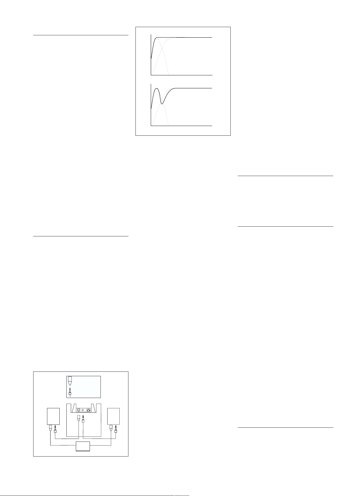
Enhancement of direct sound
85 Hz
Cancellation of direct sound
85 Hz
Figure 2: The effect of phase on the system.
conjunction with the 1029A the bass
"roll-off" (switch 2) on the 1029A should
be in the ON position. Once all connections have been made, the subwoofer
and main monitors are ready to be
powered up.
Avoiding an uneven frequency re-Avoiding an uneven frequency re-
Avoiding an uneven frequency re-
Avoiding an uneven frequency re-Avoiding an uneven frequency response.sponse.
sponse.
sponse.sponse.
Considering a usual room, a free standing speaker is always surrounded by
walls that will generate reflections. These
walls act as acoustical mirrors to the
speaker's radiation, enhancing (see top
of figure 2) or cancelling (bottom part of
figure 2), the direct sound at the listening position. The cancellation occurs at
a certain frequency which is primarily
determined by the distance from the
sub to the front wall, however the distance to other walls also affects the
cancellation frequency.
Moving the cancellation frequencyMoving the cancellation frequency
Moving the cancellation frequency
Moving the cancellation frequencyMoving the cancellation frequency
There are basically two ways to overcome this problem. The first is to position the speakers far enough from the
wall to move the interference dip below
the operating range of the speaker. To
move the dip down to 30 Hz, the distance needed is 2.8 meters. This would
not be possible in most rooms simply
because of lack of space.
The second method is to push the
speaker as close to the wall as possible
to decrease the time delay of this reflection relative to the direct sound. This
moves the interference problem to a
higher frequency. If the distance is
small enough then the frequency where
the dip occurs is above the operating
range of the subwoofer. If the distance
is decreased so the subwoofer is flush
against the wall then the mirror image of
our speaker created by the wall now
merges completely with the actual
speaker radiation. Because of this "dou-
ble" speaker effect the total sound power
radiated into the room has gained up to
6 dB.
Setting the Input SensitivitySetting the Input Sensitivity
Setting the Input Sensitivity
Setting the Input SensitivitySetting the Input Sensitivity
The subwoofer is set to the same sensitivity as the 1029A in free field conditions. However when placed near to
reflecting surfaces the sensitivity typically needs to be attenuated due to
increased room loading. A typical starting point would be -4 dB. This is
achieved by adjusting the DIP switches
on the amplifier plate. The use of proper
measuring equipment together with
careful listening is highly recommended.
The maximum attenuation by the use of
one switch is 8 dB. However an attenuation of 12 dB is possible by activating
all switches. The switches do not add
linearly.
3. Maintenance3. Maintenance
3. Maintenance
3. Maintenance3. Maintenance
No user serviceable parts are to be
found within the amplifier unit. Any maintenance of the unit should only be undertaken by qualified service personnel.
4. Safety Considerations4. Safety Considerations
4. Safety Considerations
4. Safety Considerations4. Safety Considerations
Although the 1091A has been designed
in accordance with international safety
standards, to ensure safe operation and
to keep the instrument under safe operating conditions, the following warnings and cautions should be observed.
Servicing and adjustment should only
be performed by qualified service personnel. Opening the amplifier's rear
panel is strictly prohibited except by
persons who are aware of the hazards
involved.
It is forbidden to use this product with
an unearthed mains cable, which may
lead to personal injury.
There must be at least a 100mm gap
between the amplifier plate and any
other surface or obstruction. This is to
allow sufficient air to circulate and cool
the amplifier.
WARNING!WARNING!
WARNING!
WARNING!WARNING!
This equipment is capable of delivering
sound pressure levels in excess of 85dB,
which may cause permanent hearing
damage.
5. Guarantee5. Guarantee
5. Guarantee
5. Guarantee5. Guarantee
This product is guaranteed for a period
of ONE year against faults in materials
or workmanship. Refer to supplier for
full sales and guarantee terms.
Page 3

Subwoofer positioning.Subwoofer positioning.
Subwoofer positioning.
Subwoofer positioning.Subwoofer positioning.
3
ON
GENELEC
1
3
ON
GENELEC
The figure to the left shows some example subwoofer positions within a
room.
1 Recommended position.
2
2 This arrangement may cause a loss in low frequencies if the
distance from the subwoofer position to any wall is between
1 and 3m. This position may be available beneath a mixing
console or desk.
3 Recommended only when using two subwoofers.
System Configurations.System Configurations.
System Configurations.
System Configurations.System Configurations.
The following diagrams show various ways the subwoofer can easily be included into an existing system. All connections
to the subwoofer should be of the balanced XLR type to maintain the noise immunity of the speaker system. The output of
the 1029A is of the balanced type.
2 CHANNEL
STEREO
SOURCE.
O/P LEFT
O/P RIGHT
INPUT 1
INPUT 1
MONITOR LEFT
SUB OUT
ON
GENELEC
SUB OUT
ON
GENELEC
MONITOR RIGHT
INPUT 1
INPUT 2
1091A SUBWOOFER
Subwoofer in two channel SterSubwoofer in two channel Ster
Subwoofer in two channel Ster
Subwoofer in two channel SterSubwoofer in two channel Ster
configuration.configuration.
configuration.
configuration.configuration.
Both left and right stereo channels are fed into the
corresponding monitor. Each monitor output is then connected to the subwoofer. It should be noted that the
subwoofer should only be placed at the end of the signal
chain. Never use the 1091A as a loop-through device.
eoeo
eo
eoeo
ON
GENELEC
ON
GENELEC
ON
GENELEC
INPUT 1
1091A SUBWOOFER
2
3
1
1/4" JACK
2
3
1
1/4" JACK
FRONT
RIGHT
FRONT
CENTRE
FRONT
LEFT
SIDE RIGHT
SURROUND
SOUND
PROCESSOR
SUB
SIDE LEFT
OUT
CABLE
SCREEN
CABLE
SCREEN
Subwoofer in consumer SurSubwoofer in consumer Sur
Subwoofer in consumer Sur
Subwoofer in consumer SurSubwoofer in consumer Sur
ON
GENELEC
ON
GENELEC
REAR
RIGHT
configuration.configuration.
configuration.
configuration.configuration.
When using the 1029A in a surround sound system with
the 1091A the "bass roll-off" switches on the 1029A should
rr
ound Soundound Sound
r
ound Sound
rr
ound Soundound Sound
be set to -6dB. The centre channel on the decoder should
REAR
LEFT
ON
GENELEC
ON
GENELEC
1
2
3
be set to "wide band", "large", or "full range" mode.
WW
iring diagram for interiring diagram for inter
W
iring diagram for inter
WW
iring diagram for interiring diagram for inter
connects.connects.
connects.
connects.connects.
The diagram to the left shows how to make the required
cables for the system. The connections to the subwoofer
XLR
MALE
2
3
1
1/4" JACK
are always balanced. One of each type of cable is
required.
Page 4

AUDIO
PRECISION
100
95
1091A
LEVEL(dBr)
vs
FREQ(Hz)
23
SEP9610:44:21
90
1091A RESPONSE
85
80
75
70
65
60
55
50
20
1091A SYSTEM SPECIFICATIONS1091A SYSTEM SPECIFICATIONS
1091A SYSTEM SPECIFICATIONS
1091A SYSTEM SPECIFICATIONS1091A SYSTEM SPECIFICATIONS
Free field frequency response of system (± 2.5 dB): 38 - 85 Hz
Maximum short term sine wave acoustic output in half space,
averaged from 45 Hz to 80 Hz @ 1m: >103 dB SPL
Self generated noise level in free field @ 1m on axis (A-weighted) < 10 dB
Harmonic distortion at 95 dB SPL @ 1m on axis in
half space (40...85 Hz): < 3%
Driver: 210 mm
Weight: 10.2 Kg
Dimensions: Height 505 mm (197/8")
Width 251 mm (97/8")
Depth 230 mm (9")
1029A + 1091A
RESPONSE
1029A BASS
ROLL-OFF - 6dB
SW 2 ’ON’
100
( 8")
(22.4 lb)
1029A RESPONSE
1k
AMPLIFIER SECTIONAMPLIFIER SECTION
AMPLIFIER SECTION
AMPLIFIER SECTIONAMPLIFIER SECTION
Amplifier output power : 70 W (16 Ω)
(Long term output power is limited by driver
unit protection circuitry.)
Amplifier system distortion at nominal output: TH D < 0.08%
Signal to Noise ratio, referred to full output: > 90 dB
Mains voltage: 100/200 or 115/230V
Voltage operating range: ± 10%
Power consumption (average): Idle 9 V A
10k
20k
SMPTE-IM < 0.08%
CCIF-IM < 0.08%
DIM 100 < 0.08%
Full output 100 VA
FILTER SECTIONFILTER SECTION
FILTER SECTION
FILTER SECTIONFILTER SECTION
Lowpass filter above 85 Hz: 24 dB/Octave
Subsonic filter below 40Hz 18 db/Octave
Crossover frequency, (sub/main monitors) 85 Hz
Mid Band Rejection frequency > 400 Hz: > 50 dB
Level control operating range in -2 dB steps from 0 to -8 dB
Genelec Oy, Olvitie 5Genelec Oy, Olvitie 5
Genelec Oy, Olvitie 5
Genelec Oy, Olvitie 5Genelec Oy, Olvitie 5
FIN - 74100 IISALMI, FINLANDFIN - 74100 IISALMI, FINLAND
FIN - 74100 IISALMI, FINLAND
FIN - 74100 IISALMI, FINLANDFIN - 74100 IISALMI, FINLAND
Phone:Phone:
Phone:
Phone:Phone:
Telefax:Telefax:
Telefax:
Telefax:Telefax:
Web:Web:
Web:
Web:Web:
E-mail:E-mail:
E-mail:
E-mail:E-mail:
+358 17 83881+358 17 83881
+358 17 83881
+358 17 83881+358 17 83881
+358 17 812267+358 17 812267
+358 17 812267
+358 17 812267+358 17 812267
http://www.genelec.comhttp://www.genelec.com
http://www.genelec.com
http://www.genelec.comhttp://www.genelec.com
genelec@genelec.comgenelec@genelec.com
genelec@genelec.com
genelec@genelec.comgenelec@genelec.com
(Reference to 1029A output)
INPUT SECTIONINPUT SECTION
INPUT SECTION
INPUT SECTIONINPUT SECTION
Input connectors XLR & ¼" XLR female ¼" Jack
Input impedance: 2 x 33 kΩ balanced.
Input level for 100dB SPLoutput @ 1m in full space: variable from -23dBu to
Data Sheet No. 1091-0106-1Data Sheet No. 1091-0106-1
Data Sheet No. 1091-0106-1
Data Sheet No. 1091-0106-1Data Sheet No. 1091-0106-1
COPYRIGHT GENELEC OY 1996COPYRIGHT GENELEC OY 1996
COPYRIGHT GENELEC OY 1996
COPYRIGHT GENELEC OY 1996COPYRIGHT GENELEC OY 1996
All data subject to change without prior noticeAll data subject to change without prior notice
All data subject to change without prior notice
All data subject to change without prior noticeAll data subject to change without prior notice
pin 1: gnd sleeve
pin 2: + tip
pin 3: - ring
-15 dBu in 2dB steps.
 Loading...