

Page 1
Genelec 1039A
Control Room Monitoring System
Data sheet
Page 2
1039A Control Room Monitoring System1039A Control Room Monitoring System
1039A Control Room Monitoring System
1039A Control Room Monitoring System1039A Control Room Monitoring System
APPLICATIONSAPPLICATIONS
APPLICATIONS
APPLICATIONSAPPLICATIONS
Main Monitor For LargeMain Monitor For Large
Main Monitor For Large
Main Monitor For LargeMain Monitor For Large
Control RoomsControl Rooms
Control Rooms
Control RoomsControl Rooms
SYSTEM
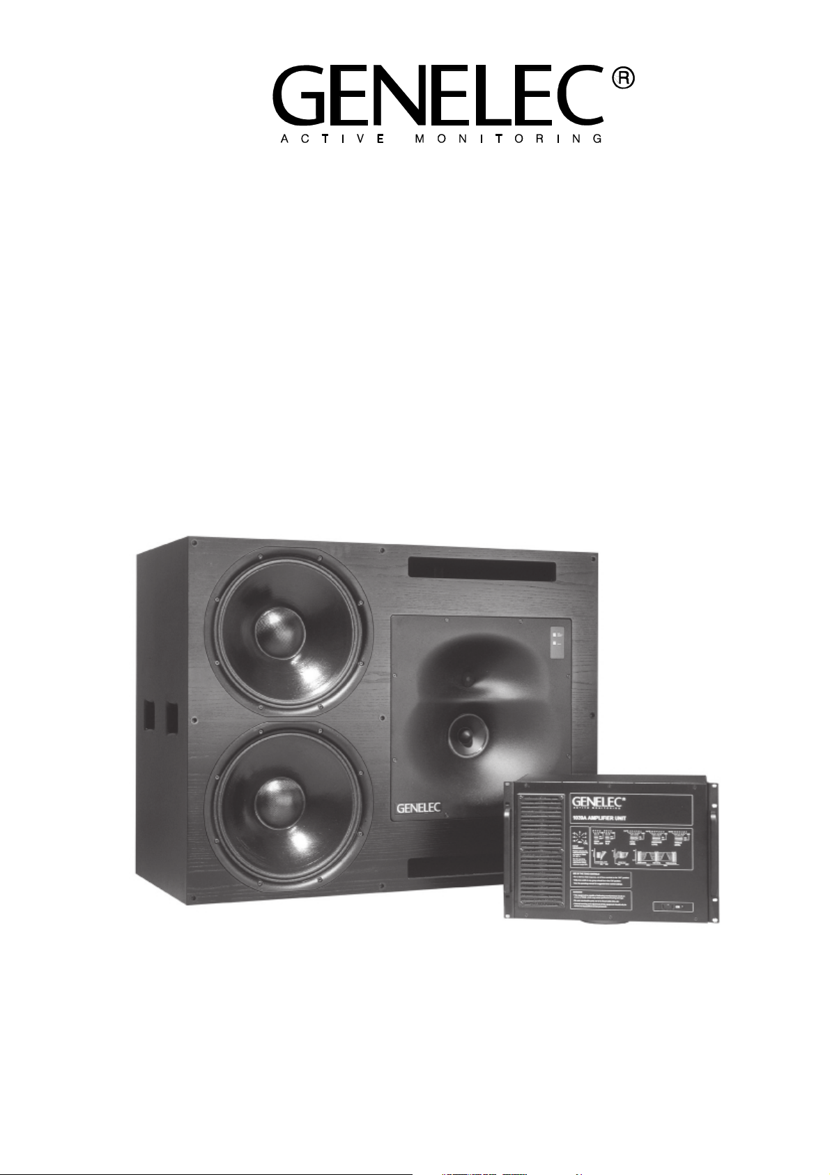
The Genelec 1039A is a very powerful monitor system, designed
for large control rooms. It consists
of a 320 litres speaker enclosure
and a 7U 19" equipment rack which
contains active crossovers, three
channel power amplifiers and
driver protection circuitry. The
speakers are designed for flush
mounting in the control room wall,
although they may be used free
standing and can produce peak
sound pressure levels in excess
of 126 dB.
Bass, midrange and treble controls are included to allow the
speakers to be matched to the
acoustic conditions in different
control rooms. The sensitivity of
the system to its environment is
minimized by the unique Directivity Control Waveguide (DCW)
Technology, which provides ex-
cellent stereo imaging and frequency balance even in difficult
acoustic situations. The system
can be used in both vertical and
horizontal orientations by simply
rotating the DCW unit.
PROTECTION CIRCUITRY
The 1039A amplifier unit contains
electronic circuitry which serves
to protect the drivers from damage by overload and distortion.
These circuits monitor each amplifier channel and automatically
reduce the signal level to the driver
if an overload condition occurs. In
addition the signal levels to all of
the drivers in the monitor are reduced by the same amount. This
preserves the frequency balance
of the monitor. A LED located on
the loudspeaker enclosure indicates the condition of this protection circuitry.
CROSSOVERFILTERAND
TREBLE/ MIDRANGE
POWERAMPLIFIERS
BALANCEDINPUT
-6...+6dBu
POWERSUPPLY
CIRCUITS
MAINSINPUT
+
_
MAINLEVEL
DRIVERPROTECTION
CIRCUITS
CROSSOVERFILTER
EHF-CAL T-CAL
BASS
ROLL-OFF
POWERSUPPLY
CIRCUITS
BASSPOWER
AMPLIFIER1
POWERSUPPLY
CIRCUITS
BASSPOWER
AMPLIFIER2
POWERAMPLIFIERS
TREBLE
LEVEL
+
-
MIDRANGE
M-CAL
LEVEL
B-CAL
BASS
BASS
LEVEL
TILT
+
-
+
-
ONLED
OVL-LED
TREBLE
MIDRANGE
BASS1
BASS2
SPEAKERCABINET
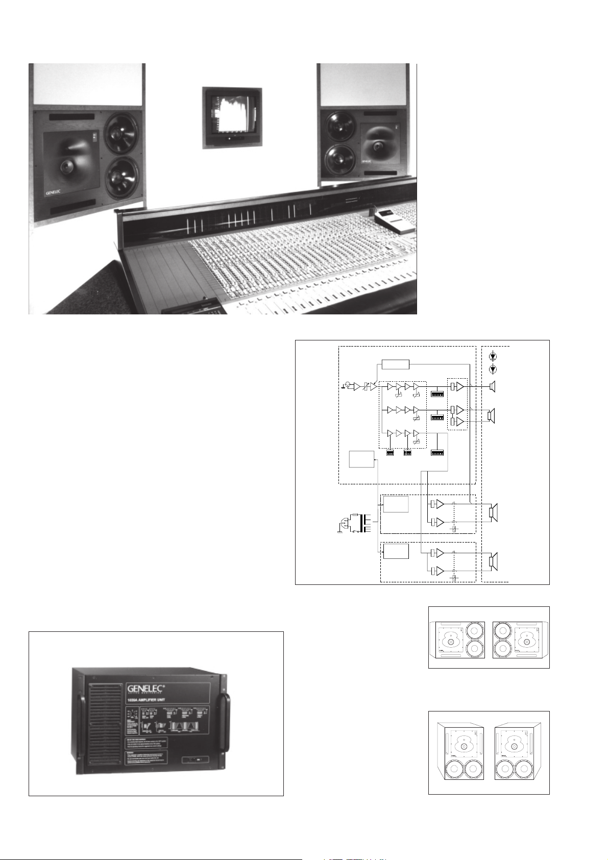
The block diagram showing active crossover filters, power amplifiers
and driver units.
AMPLIFIERS
The rack mounting amplifiers including crossover and protection.
The bass, midrange and treble
amplifiers each produce 2 x 400W,
350W and 120W of short term
power, respectively, with very low
harmonic and inter-modulation
distortion. The electronics have
been carefully designed to ensure the highest subjective sound
quality currently possible. Thermal protection is provided for the
amplifiers. A standard 10 m cable
is supplied for the speaker connection. Longer lengths are available upon special order.
Horizontal mounting
Vertical mounting
Page 3
CROSSOVER FILTERS
AUD IO PRE CISI ON 103 9ANE C vs 08 FE B 96 11:57 :41
LEV EL(d Br)
FRE Q(Hz )
The reference axis lies on the
upper midrange driver axis.
DRIVERS
Bass frequencies are reproduced
by two long throw 385 mm (15")
woofers in a vented configuration
giving a frequency response extending down to 25 Hz, with the 3 dB point at 29 Hz.
The midrange frequencies are
reproduced by a 130 mm (5") high
sensitivity direct radiating cone
driver and the high frequency
driver is a 25 mm (1") metal dome
unit, with an upper -3 dB point at
22 kHz. The mid and high frequency drivers have field replaceable diaphragms and are mounted
in a DCW for optimized directivity
control.
The active crossover network consists of three parallel band pass
filters, with crossover frequencies
at 400 Hz and 3.2 kHz, and a
common balanced input stage.
All the filters are aligned for equal
phase and group delay characteristics and are acoustically
complementary. The filter slopes
are 24 dB/octave.
To adjust the balance of the drivers to suit a particular acoustic
environment, bass midrange and
treble level controls are included,
which adjust the output in 1 dB
steps. In addition, low frequency
roll-off and 'tilt' controls are present,
to allow further refinement of the
system response.
Calibrated
ON
OFF
0dB
crossover
control
switches.
MUTE
disconnects
the channel
MUTE -6 -5 -4 -3 -2 -1
1234567
BASS
LEVEL
for testing.
90
85
80
90
85
80
90
85
80
20 100 1k 10k 20k
BAS S TILT
BAS S LE VEL
BAS S RO LL-O FF
TRE BLE L EVEL
MID LEV EL
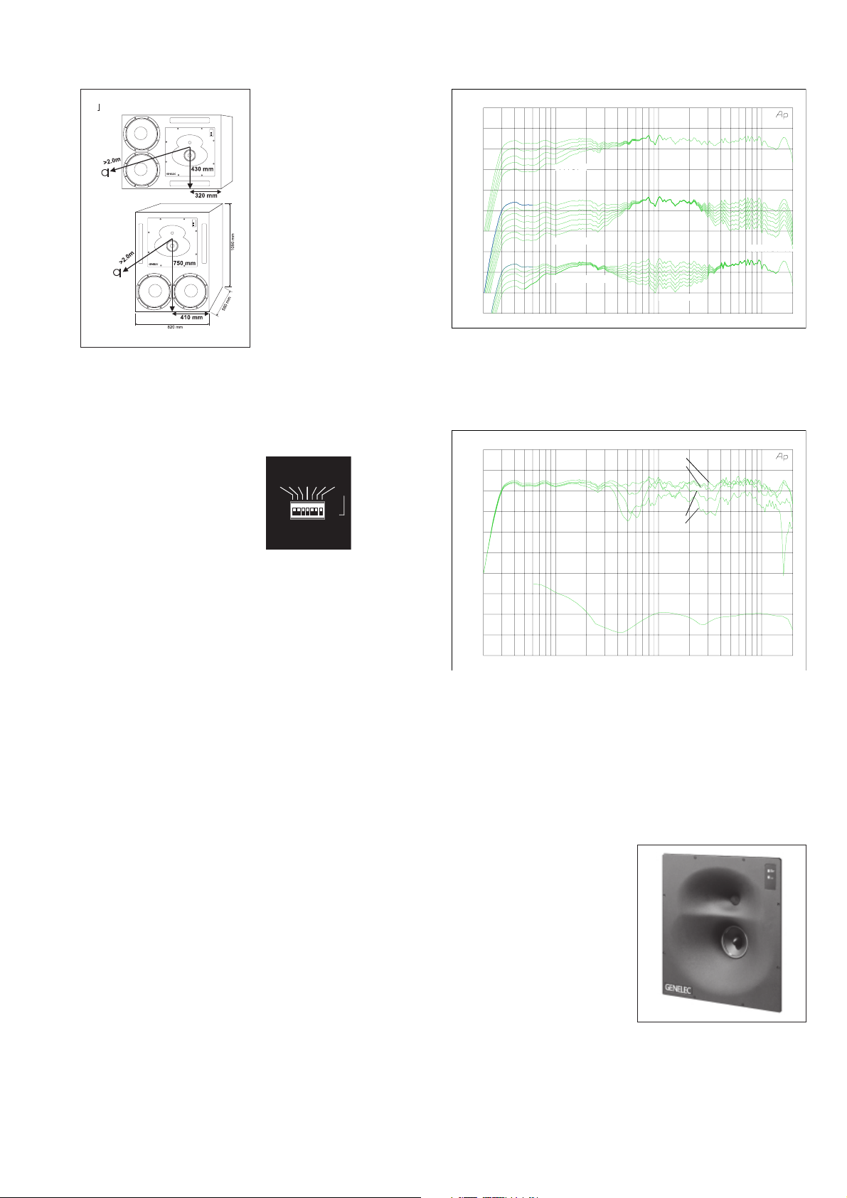
The upper curve group shows the horizontal directivity characteristics of the 1039A in its horizontal configuration measured at 2 m. The
lower curve is a 1/6 octave power response measurement, derived
from 144 directivity measurements.
AUD IO PRE CISI ON 103 9ANE C vs 08 FE B 96 12:3 6:52
95
90
85
80
75
70
65 100
95
90
85
80
20 100 1k 10k 20k
LEV EL(d Br)
FRE Q(Hz )
0°
15°
30°
45°
The curves above show the effect of the 'bass', 'mid' and 'treble'
level controls, and the 'bass tilt' and 'bass roll-off' controls on the
free field response, measured at 2 m.
SOFFIT MOUNTING
Soffit (flush) mounting of a loudspeaker removes problems
caused by diffraction effects and
reflections from the wall behind it.
Diffraction of sound at the loudspeaker cabinet edges degrades
the transient response and directional properties, while reflections
will cause interference, potentially
leading to large dips in the low
frequency response. The use of
DCW Technology removes the
diffraction effects to a large extent. Moreover, the 1039A has
versatile frequency response
controls to compensate for variations due to different speaker
positioning and room loading. This
allows it to be either soffit mounted
or to be used as a free standing
unit without using external equalization, although soffit mounting is
highly recommended.
DCW TECHNOLOGY
The revolutionary Directivity Control Waveguide Technology is a
means of greatly improving the
performance of a direct radiating
multiway loudspeaker under normal listening conditions. One of
the basic ideas is to match the
performance of the drivers in
terms of both frequency response
and directivity. This results in
smoother frequency response
both on and off axis. Also, due to
improved directivity control, especially in the midrange frequencies, more direct sound and less
reflected sound is received at the
listening position. This gives improved stereo imaging and ensures the system is less sensitive
to differing control room acoustics
than any conventional direct radiator design. The DCW Technology improves the drive unit sen-
sitivity by +2 to +6 dB thus increasing the system maximum
sound pressure level.
The high and mid frequency
drivers are mounted in a DCW
to match their dispersion
characteristics. The DCW may
be rotated for horizontal or
vertical mounting.
Page 4

1039A SYSTEM1039A SYSTEM
1039A SYSTEM
1039A SYSTEM1039A SYSTEM
SPECIFICATIONSSPECIFICATIONS
SPECIFICATIONS
SPECIFICATIONSSPECIFICATIONS
AMPLIFIERAMPLIFIER
AMPLIFIER
AMPLIFIERAMPLIFIER
SECTIONSECTION
SECTION
SECTIONSECTION
CROSSOVERCROSSOVER
CROSSOVER
CROSSOVERCROSSOVER
SECTIONSECTION
SECTION
SECTIONSECTION
Lower cut-off frequency, -3 dB: < 29 Hz
Upper cut-off frequency, -3 dB: > 20 kHz
Free field frequency response
of system: 31 Hz - 20 kHz (± 2.5 dB)
Maximum short term sine wave
acoustic output on axis
in half space, averaged from
100 Hz to 3 kHz: @ 1m > 126 dB SPL
Maximum long term RMS acoustic
output in same conditions with IECweighted noise (limited by driver unit protection circuit): @ 1m > 120 dB SPL
Maximum peak acoustic output per
pair @ 2 m from the engineer
with music material: > 126 dB
Self generated noise level in
free field @ 2m on axis: < 15 dBA
Harmonic distortion at 100 dB SPL
@ 1m on axis:
Drivers: Bass 2 x 385 mm (15") cone
Weight: Speaker 115 kg (253 lb)
Speaker dimensions (Horizontal mounting):
Amplifier dimensions:
Freq: 50...200 Hz <1%
200...10 kHz <0.5%
Mid 1 x 130 mm (5") cone
Treble 1 x 25 mm (1")
metal dome
Amplifier 30 kg (66 lb)
Height 820 mm (32
Width 1050 mm (41 1/3")
Depth 550 mm (21 5/8")
Height 310 mm (12 3/16")
Width 438 mm (19")
Depth 250 mm (9 13/16")
5/
16
Bass amplifier output power with an 8 Ohm
load:
Short term 2 x 400 W
Mid amplifier output power with a 8 Ohm
load:
Short term 350 W
Treble amplifier output power with an 8
Ohm load:
Short term 120 W
Long term output power is limited by driver
unit protection circuitry.
Slew rate : 80 V/µs
Amplifier system distortion at
nominal output:
THD <0.05%
SMPTE-IM <0.05%
CCIF-IM <0.05%
DIM 100 <0.05%
Signal to Noise ratio, referred to full output:
Bass >100 dB
Mid >100 dB
Treble >100 dB
Mains voltage: 100/200 or 115/230V
Voltage operating range at
230V setting: 207 - 244 V (-10/+6 %)
115V setting: 104 - 122 V (-10/+6 %)
Power consumption:
Idle 70 W
Full output 1000 W
")
Input connector: XLR female pin 1 gnd
pin 2 +
pin 3 -
Input impedance: 10 kOhm balanced
Input level for 100 dB SPL output @ 1m:
variable from +6 to -6 dBu
Input level for maximum short term output
of 126 dB SPL @ 1m:
variable from +32 to +20 dBu
Subsonic filter below 25 Hz :
18 dB/octave
Ultrasonic filter above 22 kHz:
12 dB/octave
Crossover frequencies:
Bass/Mid 400 Hz
Mid/Treble 3.2 kHz
Crossover acoustical slopes:
>24 dB/octave
Level control operating range in 1 dB
steps:
Bass from 0 to -6 dB & MUTE
Mid from 0 to -6 dB & MUTE
Treble from 0 to -6 dB & MUTE
Bass roll-off control in 2 dB steps:
from 0 to -8 dB @ 29 Hz
Bass tilt control in 2 dB steps:
from 0 to -8 dB @ 50 Hz
The 'CAL' position is with all tone controls
set to 'off' and input sensitivity control to
maximum and corresponds to a maximally
flat free field response.
Genelec Oy, Olvitie 5Genelec Oy, Olvitie 5
Genelec Oy, Olvitie 5
Genelec Oy, Olvitie 5Genelec Oy, Olvitie 5
FIN - 74100 IISALMI, FINLANDFIN - 74100 IISALMI, FINLAND
FIN - 74100 IISALMI, FINLAND
FIN - 74100 IISALMI, FINLANDFIN - 74100 IISALMI, FINLAND
Phone:Phone:
+358 - 17 - 813 311+358 - 17 - 813 311
Phone:
+358 - 17 - 813 311
Phone:Phone:
+358 - 17 - 813 311+358 - 17 - 813 311
Telefax:Telefax:
+358 - 17 - 812 267+358 - 17 - 812 267
Telefax:
+358 - 17 - 812 267
Telefax:Telefax:
+358 - 17 - 812 267+358 - 17 - 812 267
Web: http://www.genelec.comWeb: http://www.genelec.com
Web: http://www.genelec.com
Web: http://www.genelec.comWeb: http://www.genelec.com
E-mail: genelec@genelec.comE-mail: genelec@genelec.com
E-mail: genelec@genelec.com
E-mail: genelec@genelec.comE-mail: genelec@genelec.com
Genelec Document BBA39001Genelec Document BBA39001
Genelec Document BBA39001
Genelec Document BBA39001Genelec Document BBA39001
COPYRIGHT GENELEC OY 8/1999COPYRIGHT GENELEC OY 8/1999
COPYRIGHT GENELEC OY 8/1999
COPYRIGHT GENELEC OY 8/1999COPYRIGHT GENELEC OY 8/1999
All data subject to change without prior noticeAll data subject to change without prior notice
All data subject to change without prior notice
All data subject to change without prior noticeAll data subject to change without prior notice
 Loading...