

Page 1
1038A
DATA SHEET
Genelec 1038A
Tri-amplified Monitoring System
Page 2
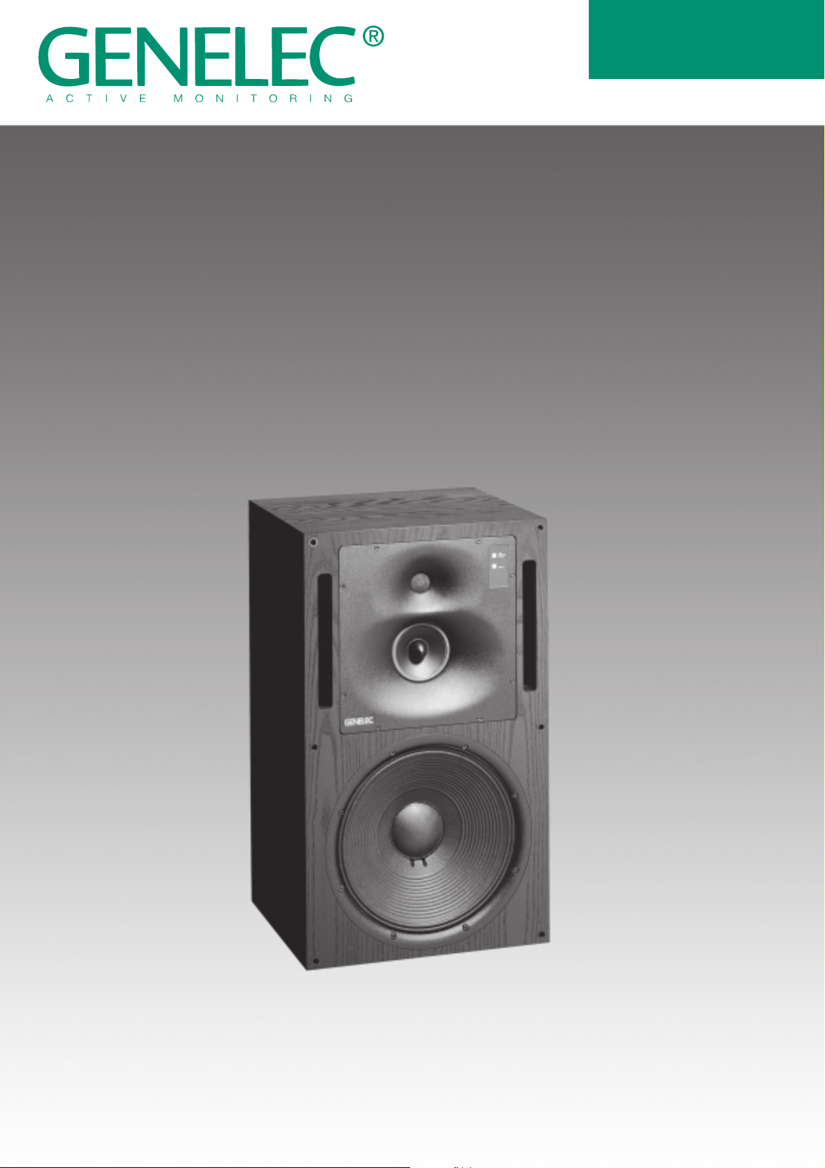
1038A Tri-amplified Active Monitoring System
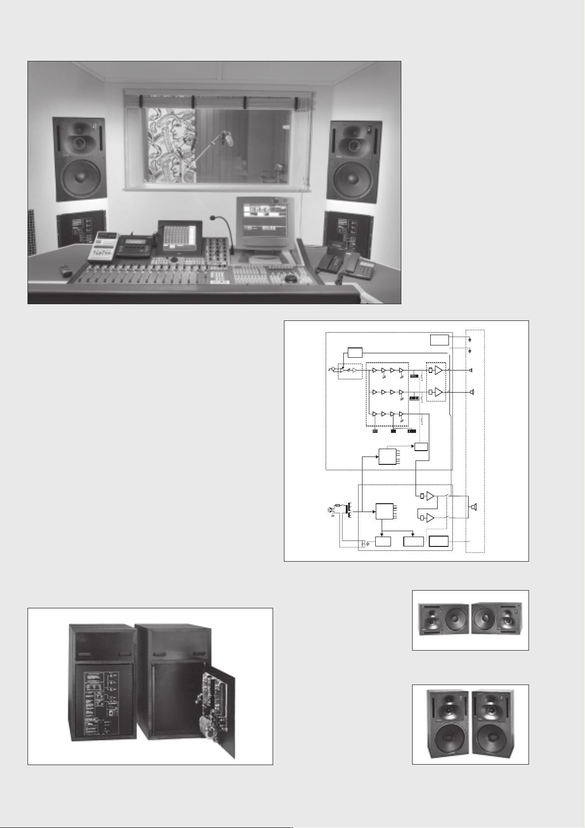
Stockholm City Theater Control room 1
SYSTEM
The Genelec 1038A is a three-way
active monitoring system including
loudspeaker drivers, speaker
enclosure, multiple power
amplifiers and active, low signal
level crossovers. Designed for
medium sized control rooms this
system is ideal for project studios,
film and video post-production
and broadcast monitoring. CD
mastering is also tailored for, where
broad bandwidth, high SPL's and
extended low frequency response
are essential. The 1038A is
designed to perform well both as
a free-standing monitor and flush
mounted into the control room wall.
The unique Directivity Control
Waveguide (DCW) Technology
used provides excellent stereo
imaging and frequency balance
even in difficult acoustic
environments. The fast, low
distortion amplifiers are capable
of driving the stereo system to
peak output levels in excess of
124 dB SPL at 2 m with program
signals. Versatile crossover
controls allow for precise matching
of the speaker system to different
acoustic conditions. The system
can be used both in vertical and
horizontal orientation by simply
rotating the DCW unit.
INTEGRATED CONSTRUCTION
The system is very easy to use as
only mains power and input signal
are needed. Uniform performance
is obtained through the integration
of the loudspeakers and amplifiers
as a complete matched and
calibrated package. The rugged
amplifier is mounted into the
enclosure with vibration isolators
which also acts as quick release
hinges making maintenance
operations easy and
straightforward. The speaker
cabinet is constructed of veneered
MDF, which is heavily braced to
eliminate structural resonances.
The block diagram showing active crossover filters, power amplifiers
and driver units.
Audio Input
-6 ... + 6 d B u
Balanced
Mains Input
!
Driver
protection
circuits
M a in L e v e l
IN P U T A M P L IF IE R
APPLICATIONS
Main monitor for medium
sized control rooms
Project Studios
Video/Film Post Production
Broadcast Monitoring
CD Mastering
CROSSOVER FILTER AND
TREBLE / MIDRANGE POWER AMPLIFIER
CRO SSOVER FILTER POW ER AMPLIFIERS
TREBLE
T-CAL
EHF-CAL
LEVEL
MID -
M-CAL
RANGE
LEVEL
B-CAL
BASS ROLL-OFF
BASS POW ER AMPLIFIER
Power Supply
circuits
Power Supply
circuits
Start delay
BASS TILT
+54V
G N D
-54V
+15V
G N D
-15V
BASS LEVEL
+54V
G N D
-54V
+15V
G N D
-15V
S tar t / sto p m u te
S h o r t p ro t e c tio n
Start/stop
Mute
PA -D rivers
C lip / p r o te c tio n
LED driver
PA -D rivers
C lip / p r o te c tio n
LED driver
SPEAKER CABINET
OVL LED
O N L E D
Treble
Midrange
Bass
To OVL-LED
Three channel amplifier is housed in the speaker cabinet
AMPLIFIERS
The bass, midrange and treble
amplifiers each produce 400W,
120W and 120W, respectively of
short term power with very low
THD and IM distortion. Special
attention has been paid to
electronic design to ensure the
highest subjective sound quality
currently possible. The system
incorporates special circuitry for
drivers overload protection.
Thermal protection is also included
for the amplifiers.
Horizontal mounting
Vertical mounting
Page 3

The reference axis lies between
midrange and tweeter drivers.
DRIVERS
CROSSOVER FILTERS
The crossover frequencies of the
active crossover network are
410 Hz and 3.0 kHz. In order to
obtain uniform frequency balance
under different acoustic
conditions, special calibrated
controls are included in the
crossover. The Bass, Midrange
and Treble level controls operate
in 1 dB steps. Furthermore, the
low frequency Tilt and Roll-off
controls both have four 2 dB steps
to allow refined LF response
tailoring. A high-pass filter is
included in the LF channel to
protect the woofer from subsonic
signals. The crossover network is
driven by an active balanced input
stage, fed by a 3 pin XLR. Variable
input sensitivity allows for accurate
level matching to the mixing
console.
The upper curve group shows the horizontal directivity characteristics
of 1038A in its vertical configuration measured at 1 m. The lower curve
is a 1/3 octave band power response, measured in an IEC approved
reverberation chamber.
The bass frequencies are
reproduced by a 385 mm (15")
bass driver loaded with a 110
liters vented box. The -3dB point
is 33 Hz and the low frequency
response extends down to 29 Hz
(-6 dB).
The midrange frequencies are
reproduced by a proprietary 130
mm (5") direct radiating cone
driver loaded with a DCW. The
high frequency driver is a 25mm
(1") metal dome also loaded by a
DCW. A factory-installed magnetic
shielding option is available for
applications where magnetic stray
field must be minimized.
DCW TECHNOLOGY
The revolutionary Directivity
Control Waveguide Technology
is a means of vastly improving the
performance of a direct radiating
multiway loudspeaker in normal
listening conditions. The basic
idea is to match the different drive
units precisely, both in terms of
frequency response and
directivity. This will result in a
smoother and a virtually
uncoloured off-axis response of
the system. Also due to improved
directivity control especially in the
midrange frequencies, more
direct sound and less early
boundary reflections are received
at the listening position. This gives
more accurate stereo imaging and
makes the system less sensitive
to differing control room acoustics
than any conventional direct
radiator design. The DCW
Calibrated
‘Level’ switch.
MUTE
disconnects
the channel for
testing.
Technology improves drive unit
sensitivity from +2 to +6 dB thus
increasing the system maximum
sound pressure level.
The tweeter and the sealed
midrange driver are mounted on a
DCW to match their dispersion
characteristics. The DCW can be
rotated for horizontal mounting.
The curves above left show the effect of the 'bass tilt', 'bass level' and
'bass roll-off' controls on the free field response. The curves to the
right show the effect of the treble and midrange 'level' controls.
Options
Opt-01
Flight case
Order Code
1038-401
Opt-03*
Magnetic
shielding
Order Code
1038-403
Opt-06*
Handles
Order Code
1001-406
* Only available as a factory-installed kit.
Opt-09
Grille
Order Code
1038-409
Opt-11
Rack adapter
Order Code
1038-411
Page 4

1038A
SYSTEM
SPECIFICATIONS
Lower cut-off frequency, -3 dB: <33 Hz
Upper cut-off frequency, -3 dB: >20 kHz
Free field frequency response
of system: 35 Hz - 20 kHz (±2.5 dB)
Maximum short term sine wave
acoustic output on axis
in half space, averaged from
100 Hz to 3 kHz:
@1m >120 dB SPL
@0.5m >126 dB SPL
Maximum long term RMS acoustic
output in same conditions with IEC-weighted
noise (limited by driver unit protection circuit):
@1m >116 dB SPL
@0.5m >122 dB SPL
Maximum peak acoustic output
per pair @ 2m from the engineer
with music material: >124 dB SPL
Self generated noise level in
free field @ 1m on axis: <15 dB
(A-weighted)
Harmonic distortion at 95 dB SPL
@ 1m on axis:
freq: 50...100 Hz <1%
>100 Hz <0.5%
Drivers: Bass 385mm (15") cone
Mid 130 mm (5") cone
Treble 25mm (1") metal dome
Weight: 60 kg (130 lb)
Dimensions: Height810mm (31 7/8")
Width 480mm (18 7/8")
Depth 420mm (16 9/16")
AMPLIFIER
SECTION
Bass amplifier output power with a 4 Ohm
load:
400W
Midrange amplifier output power with
an 8 Ohm load:
120W
Treble amplifier output power with
an 8 Ohm load:
120W
Long term output power is limited by driver
unit protection circuitry.
Slew rate : 80V/µs
Amplifier system distortion at
nominal output:
THD <0.05%
SMPTE-IM <0.05%
CCIF-IM <0.05%
DIM 100 <0.05%
Signal to Noise ratio, referred to full output:
Bass >100 dB
Midrange >100 dB
Treble >100 dB
Mains voltage: 100/200V or 115/230V
Voltage operating range at
230V setting: 207 - 253V (±10%)
115V setting: 104 - 126V (±10%)
Power consumption:
Idle 60W
Full output 500W
CROSSOVER
SECTION
Input connector: XLR female pin1 gnd
pin2 +
pin3 -
Input impedance: 10 kOhm
Input level for 100 dB SPL output @1m:
variable from +6 to -6 dBu
Input level for maximum short term output
of 120 dB SPL @1m:
variable from +26 to +14 dBu
Subsonic filter below 33 Hz :
18 dB/octave
Ultrasonic filter above 25 kHz:
12 dB/octave
Crossover frequency:
Bass/Mid 410 Hz
Mid/Treble 3 kHz
Crossover acoustical slopes:
24 - 32 dB/octave
Crossover level control operating range in 1
dB steps:
Bass from 0 to -6 dB
Mid from 0 to -6 dB
Treble from 0 to -6 dB
Bass roll-off control in 2 dB steps:
from 0 to -8 dB @ 33 Hz
Bass tilt control in 2 dB steps:
from 0 to -8 dB @ 80 Hz
The 'CAL' position is with all tone controls
set to 'off' and input sensitivity control to
maximum.
All data subject to change without prior notice.
Genelec Oy, Olvitie 5
FIN - 74100 IISALMI, FINLAND
Phone: +358 - 17 - 83 881
Fax: +358 - 17 - 812 267
E-mail: genelec@genelec.com
Web: http://www.genelec.com
Genelec Document BBA38A001a COPYRIGHT GENELEC OY 8.2000
Genelec Inc, 7 Tech Circle
Natick, MA 01760, USA
Phone: +1 - 508 - 652 - 0900
Fax: +1 - 508 - 652 - 0909
E-mail: genelec.usa@genelec.com
 Loading...