

Page 1
1036A
DATA SHEET
Genelec 1036A
Control Room Monitoring System
Page 2
1036A Control Room Monitoring System
A
-
APPLICATIONS
Main Monitor For Large
Control Rooms
SYSTEM
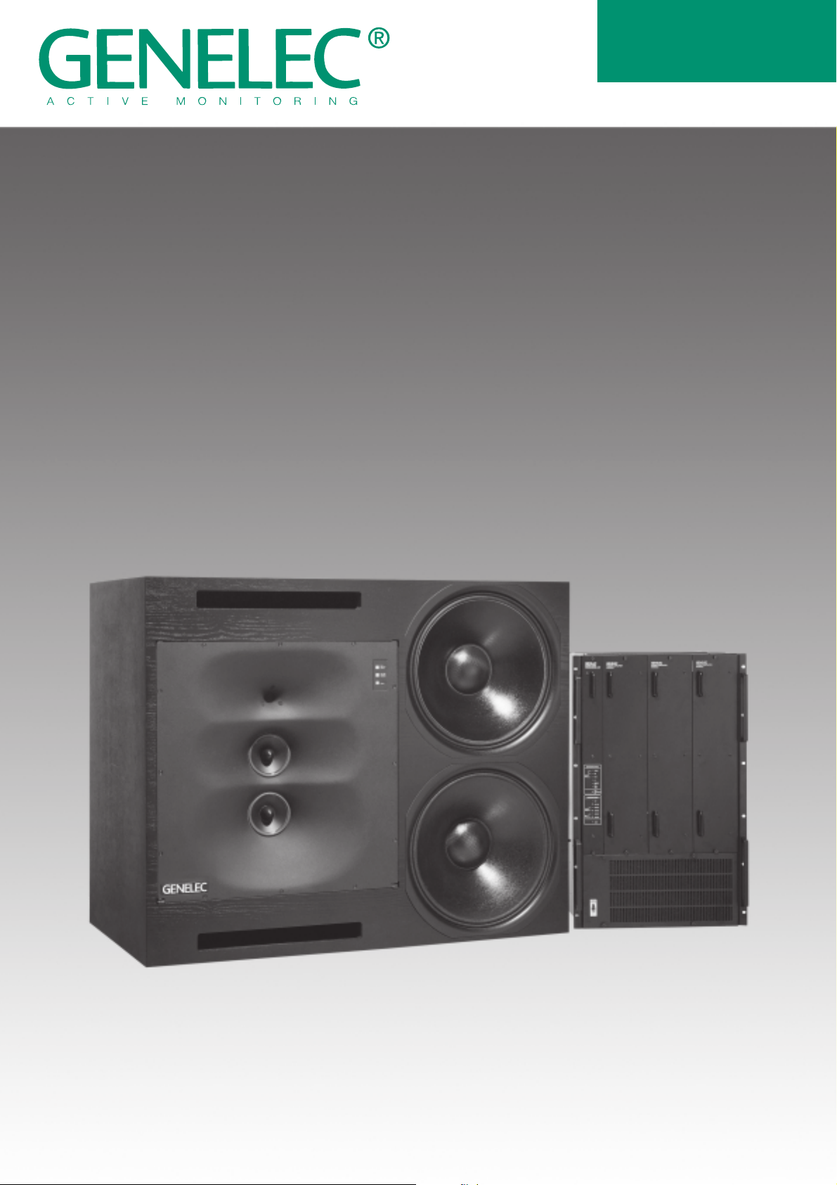
The Genelec 1036A is an extremely
powerful monitor system, designed
for large control rooms. It consists
of a 430 net liter speaker enclosure
and a 19" electronics rack, which
contains active crossovers, three
channel power amplifiers and sophisticated protection and
diagnostic circuitry. The 1036A is
designed for flush mounting in the
control room wall, although it may
be used free standing and can
produce peak sound pressure levels in excess of 136 dB.
Bass, midrange and treble controls
are included to allow the speaker to
be matched to the acoustic conditions of different control rooms. The
sensitivity of the system to its environment is minimized by the unique
Directivity Control Waveguide
(DCW) Technology, which provides
excellent stereo imaging and frequency balance even in difficult
acoustic situations. The system
can be used in both vertical and
horizontal orientations by simply
rotating the DCW unit.
PROTECTION CIRCUITRY
The Audio Processing Unit (APU),
which contains the crossover, also
contains diagnostic and protection
circuits. These monitor the amplifier channels for each driver and will
automatically reduce the monitor's
input gain, to protect a driver from
overload and distortion. Reducing
the gain of the entire monitor, rather
than just that of the overloaded
channel, preserves its frequency
balance. The protection circuitry
also guards against DC, shorting
and excessive temperature, and
will take appropriate action to prevent damage. LED displays show
the system's condition in detail on
the APU front panel and in summarized form on the loudspeaker
enclosure.
AMPLIFIERS
The treble, midrange and bass
amplifiers produce 300, 600 and 2
x 1100 watts of short term power,
respectively, with very low harmonic
and inter-modulation distortion. The
electronics have been carefully
designed to ensure the highest subjective sound quality currently
possible. Thermal protection is
provided for the amplifiers. A standard 5 m, 10 core cable is supplied
for the speaker connection. Longer
lengths are available on application.
udio Input
6 ... + 6 d B u
Balancd
1
M ains Input
2
3
AUDIO PROCESSING UNIT
CROSSOVER FILTER
IN PUT AM PLIFIER
M ain Level
LOGIC CARD
DIAGNOSTIC PANEL
LED's
Fault - Treble
- M id
- B a s s
DC
C u r re n t lim it
Over temp.
S e lf d ia g n o s tic s
Circuit
breaker
OPERATING PANEL
LED's
C lip
C lip - 3 d B
Tre b le - P ro te ctio n
- W a rn in g
M id - P ro te c tio n
- W a rn in g
Ba s s - P ro te c tio n
- W a rn in g
Ready
CROSSO VER FILTER
EHF-CAL
BASS RO LL-OFF
Driver
Protection
Display
Driver
Power Supply
Control Logic
T-CAL
M-CAL
BASS TILT
Pow er Supply
circuits
15 K
RO LL O FF
B-CAL
TREBLE
LEVEL
MIDRANGE
LEV EL
BASS LEVEL
D riv e r /
A m p lifie r
Sensors
Start / stop mute
S h o rt p ro te ctio n
Display
Driver
POW ER AMPLIFIERS
300 W
600 W
1100 W
1100 W
CLIP
DC
SHORT
OVER TEMP.
SPEAKER C ABINET
Treble
M idrange
M idrange
Bass
Bass
C L IP P R O T E C T
LED
C L IP W A R N IN G
LED
READY
LED
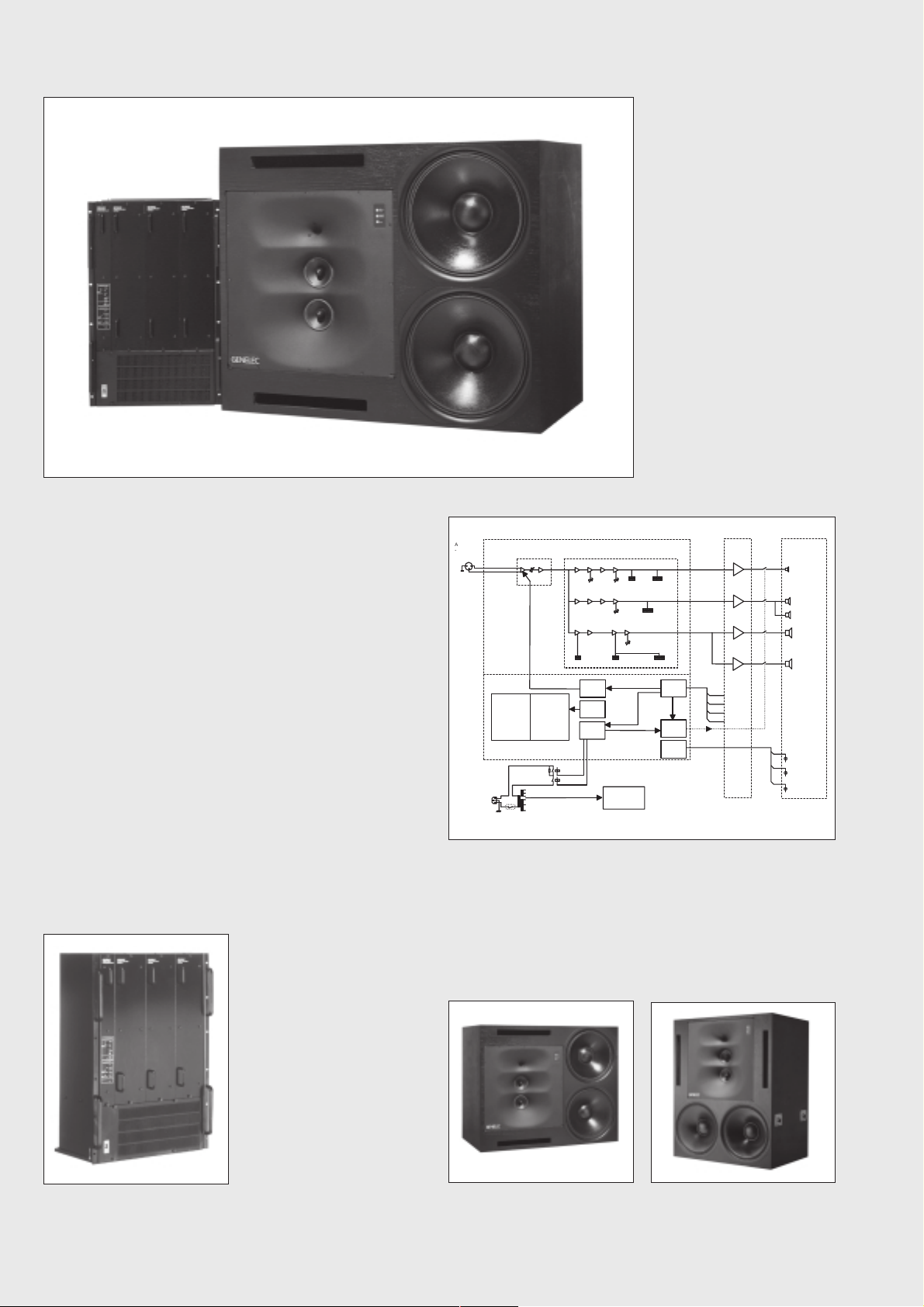
The block diagram showing active crossover filters, power amplifiers
and driver units.
The rack mounting amplifier, with
Audio Processing Unit.
Horizontal mounting
Vertical mounting
Page 3
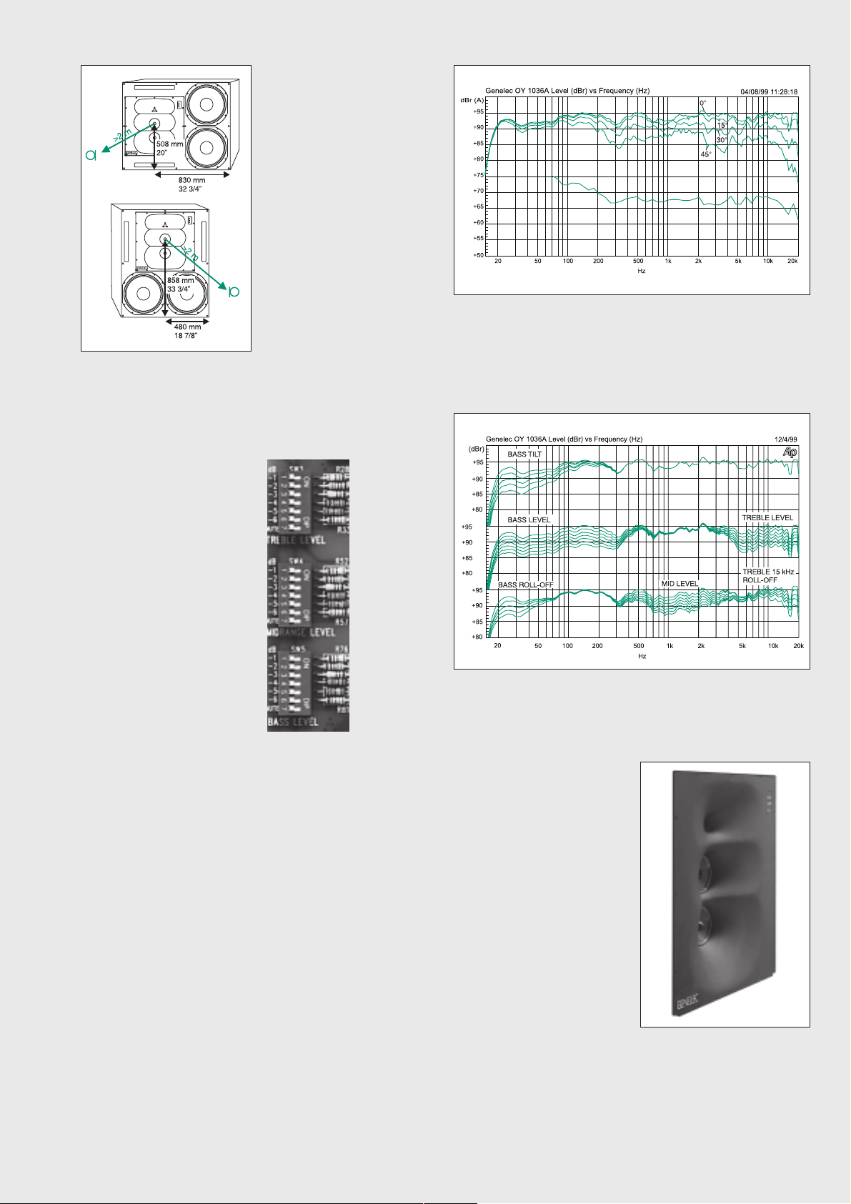
The reference axis lies on the
upper midrange driver axis.
CROSSOVER FILTERS
The active crossover network con-
sists of three parallel band pass
filters, with crossover frequencies
at 400 Hz and 3.5 kHz, and a common balanced input stage. All the
filters are aligned for equal phase
and group delay characteristics and
are acoustically complementary.
The filter slopes are 24 dB/octave.
To adjust the balance of the
drivers to suit a particular acoustic environment, bass, midrange
and treble controls are included,
which adjust the output in 1 dB
steps. In addition, a 15 kHz 'rolloff' control and low frequency rolloff and 'tilt' controls are present,
to allow further refinement of the
system response.
The upper curve group shows the horizontal directivity characteristics
of 1036A in its vertical configuration measured at 2 m. The lower
curve is a 1/6 octave power response measurement, derived from
144 individual directivity measurements.
DRIVERS
Bass frequencies are reproduced
by two long throw 460 mm (18")
woofers in a vented, dual chamber
configuration giving a frequency
response extending down to 17,5
Hz (-6dB), with the -3 dB point at 19
Hz.
The mid range frequencies are reproduced by two 130 mm (5") high
sensitivity direct radiating cone
drivers and the high frequency
driver is a 25 mm (1") throat compression driver, with an upper -3 dB
point at 22 kHz. The mid and high
frequency drivers have field replaceable diaphragms and are
mounted in a DCW.
SOFFIT MOUNTING
Soffit (flush) mounting of a loud-
speaker removes problems caused
by diffraction effects and reflections from the wall behind it:
Diffraction of sound at the loudspeaker cabinet edges degrades
the transient response and directional properties, while reflections
will cause interference, potentially
leading to large dips in the frequency response. The use of DCW
Technology reduces these effects
to a large extent and the 1036A has
versatile crossover controls to compensate for variations due to
different speaker positioning. This
allows it to be used either soffit
mounted or as a free standing unit
without using external equalization,
although soffit mounting is recommended.
Calibrated
crossover
control
switches.
MUTE
disconnects
the channel
for testing.
The curves above show the effect of the bass, mid and treble level
controls, 15 kHz roll-off control and the bass tilt and roll-off controls
on the free field response, measured at 2 m.
DCW TECHNOLOGY
The revolutionary Directivity Con-
trol Waveguide Technology is a
means of greatly improving the
performance of a direct radiating
multiway loudspeaker under normal listening conditions. One of
the basic ideas is to match the
performance of the drivers in terms
of both frequency response and
directivity. This results in smoother
frequency response both on and
off axis. Also, due to improved
directivity control, especially in the
midrange frequencies, more direct
sound and less reflected sound is
received at the listening position.
This gives improved stereo imaging and ensures the system is less
sensitive to differing control room
acoustics than any conventional
direct radiator design. The DCW
Technology improves the drive unit
sensitivity by +2 to +6 dB thus
increasing the system maximum
sound pressure level.
The high and mid frequency
drivers are mounted in a DCW
to match their dispersion
characteristics. The DCW may
be rotated for horizontal or
vertical mounting.
Page 4

1036A
SYSTEM
SPECIFICATIONS
Lower cut-off frequency, -3 dB: < 19 Hz
-6 dB: < 17,5 Hz
Upper cut-off frequency, -3 dB: > 22 kHz
Free field frequency response
of system: 21 Hz - 20 kHz (± 2.5 dB)
Maximum short term sine wave
acoustic output on axis
in half space, averaged from
100 Hz to 3 kHz:
@ 1m > 131 dB SPL
Maximum long term RMS acoustic
output in same conditions with IEC-weighted
noise (limited by driver unit protection circuit):
@ 1m > 126 dB SPL
Maximum peak acoustic output per
pair @ 2 m from the engineer
with music material: > 136 dB
Self generated noise level in
free field @ 2m on axis: < 20 dBA
AMPLIFIER
SECTION
Bass amplifier output power with an 8 Ohm
load:
Short term 2 x 1100 W
Mid amplifier output power with a 4 Ohm
load:
Short term 600 W
Treble amplifier output power with an 8
Ohm load:
Short term 300 W
Long term output power is limited by driver
unit protection circuitry.
Slew rate : 100 V/µs
Amplifier system distortion at
nominal output:
THD <0.05%
SMPTE-IM <0.05%
CCIF-IM <0.05%
DIM 100 <0.05%
Signal to Noise ratio, referred to full output:
CROSSOVER
SECTION
Input connector: XLR female pin 1 gnd
pin 2 +
pin 3 -
Input impedance: 10 kOhm balanced
Input level for 110 dB SPL output @ 1m:
variable from +15 to -5 dBu
Input level for maximum short term output of
131 dB SPL @ 1m:
variable from +36 to +16 dBu
Subsonic filter below 18 Hz :
18 dB/octave
Ultrasonic filter above 22 kHz:
12 dB/octave
Crossover frequencies:
Bass/Mid 400 Hz
Mid/Treble 3.5 kHz
Crossover acoustical slopes:
>24 dB/octave
Harmonic distortion at 100 dB SPL
@ 1m on axis:
Freq: 50...200 Hz <1%
200...4k Hz <0.5%
> 4 kHz <3%
Drivers: Bass 2 x 460 mm (18") cone
Mid 2 x 120 mm (5") cone
Treble 1 x 25 mm (1")
compression driver
Weight: Speaker 182 kg (401 lb)
Amplifier 71 kg (156 lb)
Speaker dimensions (Horizontal mounting):
Height 960 mm (37 3/4")
Width 1180 mm (46 1/2")
Depth 650 mm (25 1/2")
Amplifier dimensions:
Height 755 mm (29 3/4")
Width 483 mm (19")
Depth 370 mm (14 9/16")
Bass >101 dB
Mid >105 dB
Treble >106 dB
Mains voltage: 100/110/115/220/230/240V
Voltage operating range at
230V setting: 219 - 241 V (±5%)
115V setting: 109 - 121 V (±5%)
Power consumption:
Idle 150 W
Full output 3500 W
Level control operating range in 1 dB steps:
Bass from 0 to -6 dB & MUTE
Mid from 0 to -6 dB & MUTE
Treble from 0 to -6 dB & MUTE
Bass roll-off control in 2 dB steps:
from 0 to -8 dB @ 30 Hz
Bass tilt control operating
range in 2 dB steps:
from 0 to -8 dB @ 50 Hz
Treble roll-off control operating
range in 1 dB steps:
from +1 to -3 dB @15 kHz
The 'CAL' position is with all tone controls
set to 'off' and input sensitivity control to
maximum and corresponds to a maximally
flat free field response.
All data subject to change without prior notice.
Genelec Oy, Olvitie 5
FIN - 74100 IISALMI, FINLAND
Phone: +358 - 17 - 813 311
Fax: +358 - 17 - 812 267
E-mail: genelec@genelec.com
Web: http://www.genelec.com
Genelec Document BBA36001a COPYRIGHT GENELEC OY 8.2000
Genelec Inc, 7 Tech Circle
Natick, MA 01760, USA
Phone: + 1 - 5 08 - 652 - 090 0
Fax: +1 - 508 - 6 52 - 090 9
E-mail: genelec.usa@genelec.com
 Loading...