

Page 1
Genelec 1034BGenelec 1034B
Genelec 1034B
Genelec 1034BGenelec 1034B
Control Room Monitoring SystemControl Room Monitoring System
Control Room Monitoring System
Control Room Monitoring SystemControl Room Monitoring System
Operating ManualOperating Manual
Operating Manual
Operating ManualOperating Manual
Page 2
1. DESCRIPTION1. DESCRIPTION
A
A
1. DESCRIPTION
1. DESCRIPTION1. DESCRIPTION
The GENELEC 1034B monitor is designed
for neutral sound reproduction at high
SPLs in large control rooms. The system
comprises of a 160 litre cabinet and a 19"
7U rack mount amplifier unit.
The speaker cabinet contains two 305mm
(12") bass drivers, a 130mm (5")
midrange, and a 25mm (1") treble driver.
The midrange and treble drivers are
mounted in a Genelec Directivity Control
Waveguide (DCW) which can be rotated
through ±90° for either horizontal or vertical mounting. The cabinet low frequency 3dB point is at 32 Hz and the bass response extends down to 27 Hz. The high
frequency response extends up to 22kHz
(-3dB).
Each amplifier unit contains a 3 channel
active crossover, driver overload protection circuits, and 4 separate power amplifiers producing 2 x 400W, 350W and
120W of short term power in the bass,
midrange, and treble channels respectively. The crossover filter incorporates
tone controls to enable the user to accurately match the speaker to the local
acoustic environment.
2. UNPACKING AND2. UNPACKING AND
2. UNPACKING AND
2. UNPACKING AND2. UNPACKING AND
INSTALLATIONINSTALLATION
INSTALLATION
INSTALLATIONINSTALLATION
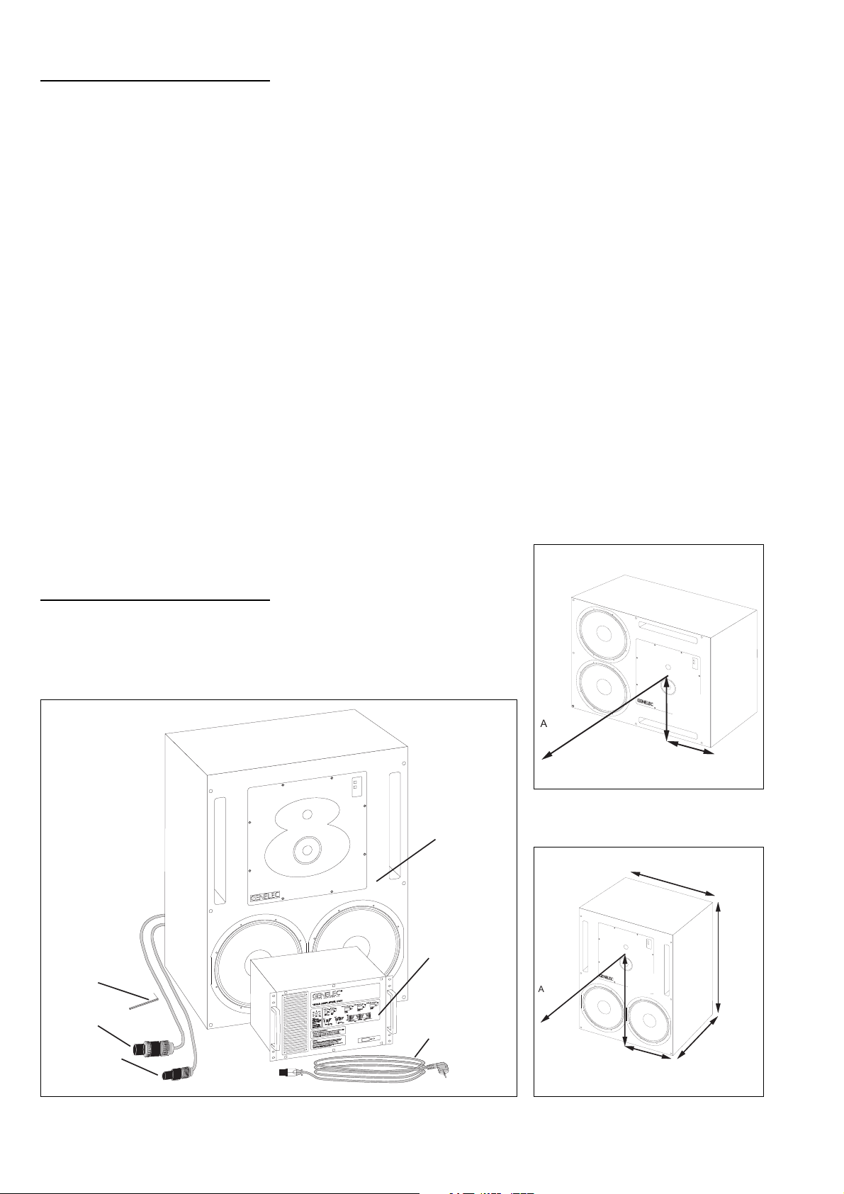
2.1 UNPACKING
The Genelec 1034B monitoring system
can be transported as a pair or as a
single system. A pair is shipped in a
single box, containing two cabinets, two
amplifier units, two mains connecting
cables, two LED connecting cables, two
loudspeaker connecting cables and one
Allen key. (See Fig 1)
Before installing the system, check all
items for damage and omissions. If there
are any damaged products, contact
directly the distributor and insurance
agent. If there are any missing components, contact your local dealer or
GENELEC.
2.2 AMPLIFIER POSITIONING
The Genelec 1034B amplifier electronics
are encased in two standard 19" 7U rack
cases. The unit should be well ventilated
to prevent excessive overheating, there
must be a supply of air to the front and
rear of the amplifier unit. If the system
overheats it will stop operating until a safe
temperature is reached.
Make sure that the amplifier is positioned
so that the speaker connecting cables will
reach. Longer cable lengths can be ordered from GENELEC upon special request. A space 100 mm (4") deep should
be left behind the rear panel of the amplifier unit to allow for the cable connectors.
Check that the amplifier unit is wired to
the correct mains voltage for your power
supply. The correct mains voltage for the
amplifier unit is shown at the bottom of the
sticker on the rear panel of the amplifier
unit.
2.3 LOUDSPEAKER POSITIONING
The 1034B control room monitor is designed to be flush mounted in either the
vertical or horizontal configuration. The
DCW should be rotated so that the treble
and midrange drivers align vertically. This
ensures that optimum stereo symmetry is
obtained.
IMPORTANT-The DCW plate is heavy,
care must therefore be taken when removing and replacing the DCW. To rotate
the DCW plate, proceed as follows:
• Place the speaker in its intended listening orientation.
• Unscrew the eight M5 fixing screws on
the edges of the plate using the 4mm
Allen key provided with the system.
• Carefully pull the plate a small distance
away from the cabinet.
• Rotate the DCW so that the midrange
and treble drivers are aligned vertically
(treble driver on top) and remount the
DCW plate reversing the procedure
above.
Allen key
Loudspeaker
connector
LED connector
Fig 1. The 1034B system.Fig 1. The 1034B system.
Fig 1. The 1034B system.
Fig 1. The 1034B system.Fig 1. The 1034B system.
Loudspeaker
cabinet
Amplifier
unit
Mains
connecting
cable
390 m m
660m m
(26")
350 m m
(15 3/8")
270m m
(10 5/8
")
700m m (27 9/16")
383 m m
coustic
axis
Fig 2.1 Horizontal configuration.Fig 2.1 Horizontal configuration.
Fig 2.1 Horizontal configuration.
Fig 2.1 Horizontal configuration.Fig 2.1 Horizontal configuration.
cou stic
axis
(13 3/4")
Fig 2.2 Vertical configuration.Fig 2.2 Vertical configuration.
Fig 2.2 Vertical configuration.
Fig 2.2 Vertical configuration.Fig 2.2 Vertical configuration.
(1 5 ")
890 m m
(35")
Page 3

2.4 FLUSH MOUNTING OF THE
SPEAKER
Although the 1034B may be used successfully as a free standing speaker, flush
mounting is strongly recommended for
acoustical reasons. Flush mounting improves the bass response and efficiency
and also enhances the midrange transient and frequency response.
The speaker has its acoustical axis midway between the midrange and treble
drivers. This axis should be used as the
listening and measuring axis of the system. (See Fig 2.1 and Fig 2.2)
The listening position should be between
2 ... 3.5m (6½ ... 11½') from the speakers.
The speaker should be aimed so that the
vertical acoustical axis of the two speakers meet midway between the standing
and seated listening position (1.4m - 4'7"
from the floor). This allows the correct
frequency response to be received by a
standing or seated person. The speakers
should not be mounted too high as this
increases the required vertical tilt of the
speaker and reduces the optimum listening area.
The ceiling, side walls and especially the
rear wall should be acoustically absorbent at low frequencies. The speaker
mounting wall should be acoustically hard
and therefore reflective. The speaker
mounting wall should be angled so that
the speakers are correctly aimed. Great
care should be taken over how the
speaker is mounted into the wall.
Note the following:
• A space 50…100 mm (2..4") wide can
be left around the speaker.
• Cover the space around the speaker
with a facing panel, this should be fixed to
the wall. Leave a gap of about 5..10 mm
(¼..½") between the speaker and the
panel. Fill this gap with a soft rubber
gasket to allow for possible cabinet movement.
• Ensure that the speaker cables can
reach the rear of the speakers.
• If a light (e.g. wooden) wall is used, the
speaker cabinet should be mounted on
vibration isolators, with a resonant frequency of around 2…8Hz, to prevent
vibrations from being transmitted to the
wall and impairing the low frequency
performance. The space around the
cabinet should be filled with absorbent
mineral wool or foam plastic. The walls
must be well braced.
• For a solid wall (e.g. concrete), the
speaker may be directly mounted to the
wall without vibration isolators. The space
around the cabinet should be filled with
mineral wool or sand bags.
Fig 3. Speaker mounting.Fig 3. Speaker mounting.
Fig 3. Speaker mounting.
Fig 3. Speaker mounting.Fig 3. Speaker mounting.
Side view (top), Plan view (bottom).Side view (top), Plan view (bottom).
Side view (top), Plan view (bottom).
Side view (top), Plan view (bottom).Side view (top), Plan view (bottom).
Fig 4. Speaker mounting details.Fig 4. Speaker mounting details.
Fig 4. Speaker mounting details.
Fig 4. Speaker mounting details.Fig 4. Speaker mounting details.
Fig 6. Recess for loudspeaker connec-Fig 6. Recess for loudspeaker connec-
Fig 6. Recess for loudspeaker connec-
Fig 6. Recess for loudspeaker connec-Fig 6. Recess for loudspeaker connectors. (Front view)tors. (Front view)
tors. (Front view)
tors. (Front view)tors. (Front view)
Discontinuities in the speaker mounting
wall will cause diffraction, which leads to
inferior frequency response and stereo
imagery, so:
• Ensure that the cabinet is flush with the
surface of the wall.
• If a decorative cloth frame is used to
cover the wall, make sure that the edges
adjacent to the speaker are less than 20
3
mm (
/4") deep. The cloth must be very
thin Tricot or acoustically transparent
material, otherwise the high frequency
response of the system will be adversely
affected. GENELEC approved cloth
grilles are available.
2.5 RECESS FOR LOUDSPEAKER
CONNECTORS
The speaker connector cable extends
100 mm (4") from the rear panel of the
loudspeaker. Therefore, a space at least
100 mm (4") deep must exist to allow for
the cable behind the loudspeaker. The
dimensions of the recess should be at
least 100x140x75 mm (4"x51/2"x3"), as
shown in Fig. 6. Note that the connectors
are positioned off-centre. Therefore, if the
loudspeaker is rotated for a left and right
channel, the recess will be at different
heights on the left and right side. This
occurs when the speakers are mounted in
the horizontal configuration.
Fig 5. Eliminating discontinuities.Fig 5. Eliminating discontinuities.
Fig 5. Eliminating discontinuities.
Fig 5. Eliminating discontinuities.Fig 5. Eliminating discontinuities.
Page 4

2.6 CONNECTING CABLE
The two connecting cables have different
types of connectors at each end, a loudspeaker connector and an LED connector. The loudspeaker connector is larger
than the LED connector, therefore the
connectors cannot be inserted into the
wrong socket. Insert the connectors into
the appropriate sockets found on the rear
panel of the amplifier unit and the rear of
the loudspeaker.
To insert the connectors proceed as
follows:
• Insert the connectors into the sockets
and turn the connectors clockwise. The
connectors lock automatically.
• The electrical connections are only
made when the connectors are fully inserted.
To remove the connectors proceed as
follows:
• Pull the release lever on the connector
and turn the connector counterclockwise
simultaneously. The connector can now
be removed from the socket.
Speaker connector
LED connector
PUSH
21
3
3. ACOUSTICAL SETUP3. ACOUSTICAL SETUP
3. ACOUSTICAL SETUP
3. ACOUSTICAL SETUP3. ACOUSTICAL SETUP
3.1 INPUT SENSITIVITY ADJUSTMENT
The input sensitivity of the 1034B can be
adjusted to match the output signal level
of the driving source . This is done by
turning the 'Input sensitivity' trimmer,
which is accessed through the front panel
of the amplifier unit. However, an accurate left/right balance is obtained when
the trimmer is set to the fully clockwise
'cal' position. Leaving the input sensitivity
trimmer in the 'cal' position is therefore
recommended.
To obtain the maximum sound pressure
level of 123 dB SPL, with the input sensitivity set to -6 dBu, a signal level of +20
dBu is required.
3.2 ADJUSTMENT OF THE TONE CONTROLS
The frequency response of the system
should be adjusted to match the listening
room's acoustic environment. This adjustment is made using the tone controls,
'BASS TILT', 'BASS ROLL-OFF', 'BASS
LEVEL', 'MIDRANGE LEVEL', and
'TREBLE LEVEL'. These controls are accessed through the amplifier unit's front
panel. The default setting of these controls is in the 'off' position, which yields a
flat frequency response when the speaker
is operated in an anechoic environment.
Note that only one switch in each control
group should be in the 'on' position.
The room normally boosts the low frequencies compared with free field conditions. To get a flat room response, adjustments to the bass tone control switches
are usually required. See table 1 below
for suggested starting positions of the
tone controls in four different room types.
The table shows that the midrange and
treble controls should be left in their free
field positions, since these frequencies
are controlled by the speaker more than
the room. Acoustical measurements, and
precise listening tests should be completed by qualified personnel, to determine the optimum tuning of the speaker
to the room.
3.3 FREQUENCY RESPONSE MEASUREMENT IN THE CONTROL ROOM
The overall sound balance experienced
at the listening position can, to a certain
extent, be measured with steady state
signals (e.g. pink noise, warble sine etc.)
and a corresponding frequency analyser.
However, the results obtained are very
sensitive to the measuring methods and
the equipment used.
Recommended Measuring Equipment.Recommended Measuring Equipment.
Recommended Measuring Equipment.
Recommended Measuring Equipment.Recommended Measuring Equipment.
Microphone
• Always use a laboratory grade measurement microphone.
• B&K 4134 (or similar) for far field, 4133
or 4165 (or similar) for near field below
8kHz.
• B&K 4004 and 4007 (or similar) up to
8kHz.
Do not
use a microphone having a polar
pattern other than omnidirectional, or one
not having an accurately known frequency response.
Input connectorM ains connector
Fig 7. Amplifier unit connectors.Fig 7. Amplifier unit connectors.
Fig 7. Amplifier unit connectors.
Fig 7. Amplifier unit connectors.Fig 7. Amplifier unit connectors.
Turn connector
clockw ise to co nne ct.
Turn connector
R elease lever.
P u ll le v e r to u n lo c k
w hilst disconnecting.
Fig 8. Speaker/LED connectorFig 8. Speaker/LED connector
Fig 8. Speaker/LED connector
Fig 8. Speaker/LED connectorFig 8. Speaker/LED connector
counterclockw ise to
disconnect.
S t ra in r e lie f
DO NOT LOOSEN!
Speaker Mounting Environment
1. Flat anechoic response
(factory setting)
2. Free standing in a heavily
damped room
3. Free standing in a
reverberant room
4. Flush mounted in a hard wall ALL OFF
5. In a corner
Table 1. Suggested starting positions for tone controls.Table 1. Suggested starting positions for tone controls.
Table 1. Suggested starting positions for tone controls.
Table 1. Suggested starting positions for tone controls.Table 1. Suggested starting positions for tone controls.
Bass roll off Bass tilt Bass level Mid level Treble level
ALL OFF ALL OFF ALL OFF ALL OFF ALL OFF
ALL OFF
ALL OFF
-4 dB
ON
-2 dB
ON
-2 dB
ON
-4 dB
ON
-6 dB
ON
Control
ALL OFF ALL OFF ALL OFF
-1 dB
ON
-1 dB
ON
-2 dB
ON
ALL OFF ALL OFF
ALL OFF ALL OFF
ALL OFF ALL OFF
Page 5

Signal Source
Use a signal source which is suitable for
the type of analyser being used.
use a noise generator which is integrated
into a mixing console, since these signal
generators tend to have a very coarse
spectrum content and are not intended to
be used for measurement purposes.
Do not
Analyser
Any professional quality real time analyser
or tracking plotter can be used. (1/3 or 1/1
octave analysis is usually sufficient for
frequency response balancing)
3.4 NEAR FIELD MEASUREMENT.
This measurement gives an indication of
the direct sound radiation of the loudspeaker below 1kHz.
• Set the microphone 1m away from the
loudspeaker on the acoustic axis. (See
Fig 2.1 and 2.2)
• Measure the frequency response of
the speaker, and adjust the tone controls
to achieve a flat frequency response
below 1kHz.
• Reflections from nearby boundaries
(Floor, ceiling, walls) interfering with direct
sound.
Incorrect vertical speaker alignment can
cause interference dips at the upper
crossover frequency (around 3.2kHz).
Hence care should be taken aiming the
speaker correctly towards the listening
position. (See Fig 3.)
4. OVERLOAD INDICATORS4. OVERLOAD INDICATORS
4. OVERLOAD INDICATORS
4. OVERLOAD INDICATORS4. OVERLOAD INDICATORS
Each speaker is provided with two LED's
marked 'CLIP PROTECT (FAULT)' and
'READY'. The green 'READY' LED indicates that the amplifier system power is
switched on, and that the speaker is
ready for use. The red 'CLIP PROTECT
(FAULT)' LED indicates that the amplifier
system is overloaded or that the driver
protection circuit is activated. If the red
LED lights, reduce the signal level so that
the LED stops blinking. If this LED stays lit
constantly, then the amplifier thermal
protection circuitry has activated. Let the
amplifier cool down, and ensure that the
amplifier is adequately ventilated.
ating conditions, the following warnings
and cautions should be observed.
Servicing and adjustment should only be
performed by qualified service personnel.
Opening the amplifier's front panel is
strictly prohibited except by such persons
who are aware of the hazards involved.
It is forbidden to use this product with an
unearthed mains cable, which may lead
to personal injury.
Warning!
This equipment is capable of delivering
sound pressure levels in excess of 85dB,
which may cause permanent hearing
damage.
7. GUARANTEE7. GUARANTEE
7. GUARANTEE
7. GUARANTEE7. GUARANTEE
This product is guaranteed for a period of
ONE year against faults in materials or
workmanship. Refer to supplier for full
sales and guarantee terms.
Make sure that any sound reflecting objects such as chairs etc. are removed
from the close proximity of the loudspeaker.
3.5 LISTENING POSITION MEASUREMENT.
Once the near field frequency response
measurement has been made, the frequency response at the listening position
can be determined by the same means.
When comparing the results, the following
items should be noted.
High frequency roll-off
This is due to the following physical factors:
• Increasing room and air absorption
with higher frequencies.
• Increasing loudspeaker and microphone directivity with increasing frequency.
Low frequency irregularities.
These are caused by
• Insufficient standing wave absorption
in the control room.
5. MAINTENANCE5. MAINTENANCE
5. MAINTENANCE
5. MAINTENANCE5. MAINTENANCE
There are no user serviceable parts within
the amplifier unit. Any maintenance of the
unit should only be undertaken by qualified service personnel.
Ensure that only fuses of the appropriate
voltage and current ratings are used if a
fuse has to be replaced.
REMEMBER to disconnect the power
supply by removal of the mains cable
before changing a fuse.
Clean the amplifier unit's air filter every six
months, or more frequently in dusty environments. The air filter is located behind
the grille, found to the left of the front
panel. The air filter can be cleaned with a
vacuum cleaner without removing the
grille.
6. SAFETY CONSIDERATIONS6. SAFETY CONSIDERATIONS
6. SAFETY CONSIDERATIONS
6. SAFETY CONSIDERATIONS6. SAFETY CONSIDERATIONS
Although the 1034B has been designed in
accordance with international safety standards, to ensure safe operation and to
maintain the instrument under safe oper-
Page 6

Fig 9. The above curves illustrates the effect of the 'bass tilt',Fig 9. The above curves illustrates the effect of the 'bass tilt',
Fig 9. The above curves illustrates the effect of the 'bass tilt',
Fig 9. The above curves illustrates the effect of the 'bass tilt',Fig 9. The above curves illustrates the effect of the 'bass tilt',
'bass roll-off' and 'bass',' mid' and 'treble' level controls on the'bass roll-off' and 'bass',' mid' and 'treble' level controls on the
'bass roll-off' and 'bass',' mid' and 'treble' level controls on the
'bass roll-off' and 'bass',' mid' and 'treble' level controls on the'bass roll-off' and 'bass',' mid' and 'treble' level controls on the
free field response, measured at 2 m.free field response, measured at 2 m.
free field response, measured at 2 m.
free field response, measured at 2 m.free field response, measured at 2 m.
Fig 10. The upper curve group shows the horizontal directivityFig 10. The upper curve group shows the horizontal directivity
Fig 10. The upper curve group shows the horizontal directivity
Fig 10. The upper curve group shows the horizontal directivityFig 10. The upper curve group shows the horizontal directivity
characteristics of the 1034B in its horizontal configuration mea-characteristics of the 1034B in its horizontal configuration mea-
characteristics of the 1034B in its horizontal configuration mea-
characteristics of the 1034B in its horizontal configuration mea-characteristics of the 1034B in its horizontal configuration measured at 2m. The lower curve is a 1/6 octave power responsesured at 2m. The lower curve is a 1/6 octave power response
sured at 2m. The lower curve is a 1/6 octave power response
sured at 2m. The lower curve is a 1/6 octave power responsesured at 2m. The lower curve is a 1/6 octave power response
measurement, derived from 144 directivity measurements.measurement, derived from 144 directivity measurements.
measurement, derived from 144 directivity measurements.
measurement, derived from 144 directivity measurements.measurement, derived from 144 directivity measurements.
SYSTEM SPECIFICATIONSSYSTEM SPECIFICATIONS
SYSTEM SPECIFICATIONS
SYSTEM SPECIFICATIONSSYSTEM SPECIFICATIONS
Lower cut-off frequency, -3 dB: < 32 Hz
Upper cut-off frequency, -3 dB: > 20 kHz
Free field frequency response of system:
33 Hz - 20 kHz (± 2.5 dB)
Maximum short term sine wave acoustic output
on axis in half space, averaged from 100 Hz to 3
kHz:@ 1m > 123 dB SPL
Maximum long term RMS acoustic output in
same conditions with IEC-weighted noise
(limited by driver unit protection circuit):
@ 1m > 118 dB SPL
Maximum peak acoustic output per pair @ 2m
from the engineer with music material:
> 125 dB
Self generated noise level in free field @ 2m on
axis: < 15 dB(A)
Harmonic distortion at 100 dB SPL @ 1m on axis:
Freq: 50...200 Hz <1%
200...10k Hz <0.5%
Drivers:
Bass 2 x 305 mm (12") cone
Mid 1 x 130 mm (5") cone
Treble 1 x 25 mm (1") metal dome
Weight: Speaker 73 Kg (161 lb)
Amplifier 30 Kg (66 lb)
Speaker dimensions (Horizontal mounting):
Height 700 mm (279/16")
Width 890 mm (35")
Depth 383 mm (15")*
Amplifier dimensions:
Height 310 mm (123/16")
Width 483 mm (19")
Depth 250 mm (913/16")*
*Note that the cable connectors require
additional 100 mm (4") of space behind both the
amplifier and the speaker cabinet
AMPLIFIER SECTIONAMPLIFIER SECTION
AMPLIFIER SECTION
AMPLIFIER SECTIONAMPLIFIER SECTION
Bass amplifier output power with an 8 Ohm load:
Short term 2 x 400 W
Mid amplifier output power with a 8 Οhm load:
Short term 350 W
Treble amplifier output power with an 8 Ohm
load: Short term 120 W
Long term output power is limited by driver unit
protection circuitry.
Slew rate: 80 V/µs
Amplifier system distortion at nominal output:
THD <0.05%
SMPTE-IM <0.05%
CCIF-IM <0.05%
DIM 100 <0.05%
Signal to Noise ratio, referred to full output:
Bass >100 dB
Mid >100 dB
Treble >100 dB
Mains voltage: 100/200 or 115/230V
Voltage operating range at
230V setting: 207 - 244 V (-10/+6 %)
115V setting: 104 - 122 V (-10/+6 %)
Power consumption:
Idle 70 W
Full output 1000 W
CROSSOVER SECTIONCROSSOVER SECTION
CROSSOVER SECTION
CROSSOVER SECTIONCROSSOVER SECTION
Input connector: XLR female pin 1 gnd
pin 2 +
pin 3 Input impedance: 10 kOhm balanced
Input level for 100 dB SPL output @ 1m:
variable from +6 to -6 dBu
Input level for maximum short term output of 126
dB SPL @ 1m:
variable from +32 to +20 dBu
Subsonic filter below 27 Hz :
18 dB/octave
Ultrasonic filter above 22 kHz:
12 dB/octave
Crossover frequencies:
Bass/Mid 400 Hz
Mid/Treble 3.2 kHz
Crossover acoustical slopes:
>24 dB/octave
Level control operating range in 1 dB steps:
Bass from 0 to -6 dB & MUTE
Mid from 0 to -6 dB & MUTE
Treble from 0 to -6 dB & MUTE
Bass roll-off control in 2 dB steps:
from 0 to -8 dB @ 29 Hz
Bass tilt control operating range in 2 dB steps:
from 0 to -8 dB @ 50 Hz
The 'CAL' position is with all tone controls set to
'off' and input sensitivity control to maximum and
corresponds to a maximally flat free field
response.
Genelec Oy, Olvitie 5Genelec Oy, Olvitie 5
Genelec Oy, Olvitie 5
Genelec Oy, Olvitie 5Genelec Oy, Olvitie 5
FIN - 74100 IISALMI, FINLANDFIN - 74100 IISALMI, FINLAND
FIN - 74100 IISALMI, FINLAND
FIN - 74100 IISALMI, FINLANDFIN - 74100 IISALMI, FINLAND
Phone:Phone:
+358 17 813311+358 17 813311
Phone:
+358 17 813311
Phone:Phone:
+358 17 813311+358 17 813311
Telefax:Telefax:
+358 17 812267+358 17 812267
Telefax:
+358 17 812267
Telefax:Telefax:
+358 17 812267+358 17 812267
E-mail:E-mail:
genelec@genelec.comgenelec@genelec.com
E-mail:
genelec@genelec.com
E-mail:E-mail:
genelec@genelec.comgenelec@genelec.com
Web:Web:
http://www.genelec.comhttp://www.genelec.com
Web:
http://www.genelec.com
Web:Web:
http://www.genelec.comhttp://www.genelec.com
Genelec Document DR34001Genelec Document DR34001
Genelec Document DR34001
Genelec Document DR34001Genelec Document DR34001
COPYRIGHT GENELEC OY 1998COPYRIGHT GENELEC OY 1998
COPYRIGHT GENELEC OY 1998
All data subject to change without prior noticeAll data subject to change without prior notice
All data subject to change without prior notice
All data subject to change without prior noticeAll data subject to change without prior notice
COPYRIGHT GENELEC OY 1998COPYRIGHT GENELEC OY 1998
 Loading...