

Page 1

1029A
Data Sheet
Genelec 1029A
Bi-amplified Monitoring System
Page 2
1029A Active Monitoring System
Applications
• Near Field Monitoring
• Audio Video Post Pro duc tion
• Mobile Vans
• Home Theaters
• Project / Home Studios
• Digital Workstations
• Multimedia Production and
Playback
System
The Genelec 1029A is a very com pact bi-
amplifi ed active monitor system, which has
performance comparable to much larger
sys tems. The vented speaker en clo sure con-
tains an am pli fi ca tion unit. This unit includes
an active electronic crossover, over load
protection circuitry and two power amplifi ers,
one for each driver. The system's excellent
dis per sion and precise imaging, to geth er
with its compact size, make it ideal for near
fi eld mon i tor ing, mobile vans, home studios,
multimedia and home theaters.
The Genelec 1029A has been spe cial ly
designed to have a suffi cient LF extension
(-3 dB at 68 Hz) for most monitoring applica-
tions. However if greater SPL's and a lower
cutoff frequency are re quired, it can be com-
plemented with the 7050A subwoofer, which
has a lower cutoff point of 38 Hz.
Genelec’s unique Directivity Con trol Wave-
guide (DCW) tech nol o gy is used to provide
excellent ster eo imaging and frequency bal-
ance, even in diffi cult acoustic en vi ron ments.
Versatile tone con trols al low further matching
of the system to its surroundings. A pair of
1029A's can produce peak acoustic levels of
over 110 dB SPL at 1 m.
Integrated construction
The 1029A is very easy to set up and use,
the only con nec tions re quired are the mains
supply and the line level input.
The integrated design allows the am pli fi ers
and the drivers to be cal i brat ed as a single
unit, elim i nat ing the effects of com po nent
tolerances and en sur ing con sist ent quality.
The rugged cast alu min i um cabinet has
round ed cor ners and a hard-wear ing paint ed
outer surface.
Crossover filters
The amplifi er unit contains an ac tive cross-
over, a feature more com mon ly used in large
and ex pen sive control room monitors. This
is the ideal method for di vid ing the input
signal between the driver units. The active
crossover allows the overall response of
the system to be optimized to an ex tent
im pos si ble with a passive system. To main-
tain uniform fre quen cy bal ance in differing
acous tic en vi ron ments, special calibrated
controls are included in the active crossover
network. These con trols include treble 'tilt',
bass 'tilt' and bass 'roll-off' switch es.
Input connectors
The input is made via a balanced female XLR
or a balanced
two input connectors offer great fl exibility as
they can be used in parallel. This offers the
possibility of hav ing two sources connected
to the monitor at the same time. An additional
confi guration is using a single 1029A to mon-
itor a stereo output. See fi gures 3 and 4.
The volume control is located on the front
panel. This allows easy level matching with
other audio equipment.
1
/4" jack socket connector. The
Amplifiers
The bass and treble amplifi ers produce
40 W of output power each, with very low
THD and IM distortion values. The amplifi ers
are designed to ensure the high est subjective
Page 3

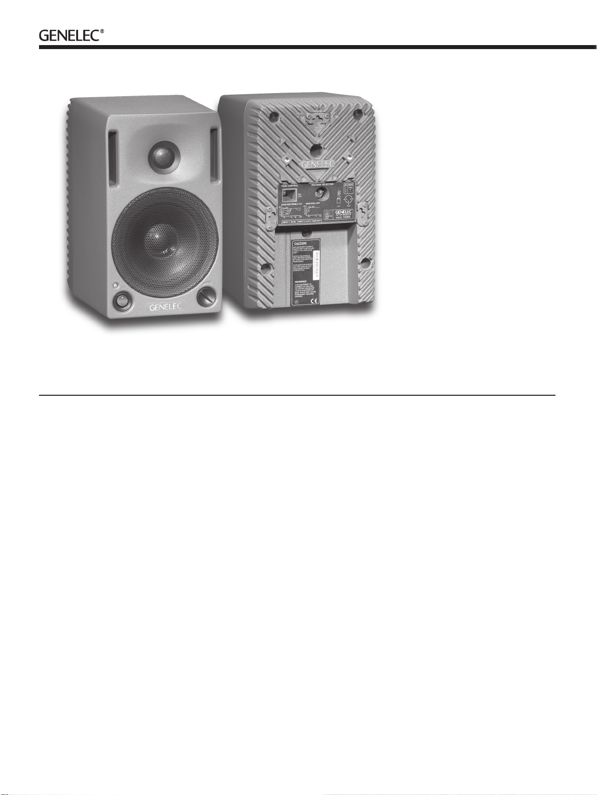
Figure 1: 1029A’s reference axis is located
between the bass and treble drivers.
Figure 2: Control and connector layout on the rear panel of a 1029A.
Figure 3: Monitoring two sources.
sound quality cur rent ly possible. The amplifi er unit also contains a protection cir cuit that
monitors the output levels and prevents any
damage to the driv ers. This makes the system
im mune to overloads and spu ri ous signals.
Drivers
A 19 mm (3/4") metal dome tweeter is loaded
by a DCW, and is used to reproduce the high
fre quen cies. The DCW is integrated into the
one piece cabinet front baffl e.
The 130 mm (5") woofer is a bass cone
driver mounted in a 4.5 litre vented cabinet.
The -3 dB fre quen cy is 68 Hz and the low
fre quen cy response extends down to 65 Hz
(-6 dB).
Protective grilles are positioned in front of
both drivers. Magnetic shielding is standard
on the 1029A. Shielding is vital for applications such as video post production, where
stray mag net ic fi elds must be minimized.
DCW Technology
The revolutionary Directivity Con trol Waveguide (DCW) tech nol o gy is a means of
Figure 4: Mono monitoring of a stereo
source
greatly improving the performance of a direct
ra di at ing multi-way loudspeaker un der nor mal listening conditions.
One of the basic aims is to match the performance of the drivers in terms of both frequency re sponse and directivity. This results
in a smoother overall frequency re sponse on
and off axis. In ad di tion, the improved directivity control causes more direct sound and
less refl ected sound to be re ceived at the
listening position. This provides improved
stereo imaging and ensures that the sys tem
is less sensitive to differing control room
acoustics than con ven tion al direct radiator
design. The DCW Technology improves the
drive unit sensitivity by +2 to +6 dB (depending on the par tic u lar application), thus also
in creas ing the available system maximum
sound pressure level.
Mounting
There are several pos si bil i ties for mounting
the 1029A. On the base of the monitor is a
3
/8" UNC thread ed hole which can ac com -
mo date a standard mi cro phone stand. There
Figure 5: 1029A connected to a 7050A
subwoofer (only one channel shown).
is a provision for an Om n i mount® size 50
bracket, for which two M6x10mm screws
are re quired. Al ter na tive ly the speak er can
be hung on M4 screws with suitable heads
by one of the three key hole slots on the
backpanel. The speaker can be hung in a
hor i zon tal or vertical position. Fric tion pads
are pro vid ed for place ment on a shelf or a
stand.
Options
The 1029A is available in three colours:
black, grey and white. The driver's protective
grilles, volume and power knobs and stickers on the back of the loud speak er are black
except for the bass driver grille on the white
version, which is white.
Oth er op tions in clude wall and ceiling
mounts, ta ble stand and soft car ry ing bag.
Ask your local Genelec dealer for more
details.
Page 4

1029A Data Sheet
Figure 6: The curve above shows the effect of the ‘treble tilt’, ‘bass tilt’
and ‘bass roll-off’ controls on the free field response.
SYSTEM SPECIFICATIONS
Lower cut-off frequency, –3 dB: < 68 Hz
Upper cut-off frequency, –3 dB: >
Free field frequency response of system:
70 Hz –18 kHz (± 2.5 dB)
Maximum short term sine wave acoustic output on axis
in half space, averaged from 100 Hz to 3 kHz:
@ 1m >
@ 0.5m >
Maximum long term RMS acoustic output in same
conditions with IEC weighted noise (limited by driver unit
protection circuit): @ 1m >
@ 0.5m >
Maximum peak acoustic output per pair on top of
console, @ 1 m from the engineer with music material:
>
Self generated noise level in free field @ 1m on axis:
< 10 dB (A-weighted)
Harmonic distortion at 85 dB SPL @ 1m on axis:
Freq: 75…150 Hz < 3%
> 150 Hz < 1%
Drivers: Bass 130 mm (5") cone
Treble 19 mm (
Both drivers are
magnetically shielded
20 kHz
100 dB SPL
106 dB SPL
98 dB SPL
104 dB SPL
110 dB
3
/4") metal dome
Weight: 5.7 kg (12.5 lb)
Dimensions: Height 247 mm (93/4")
Width 151 mm (5
Depth 191 mm (7
15
/16")
1
/2")
Inputs: Input 1: XLR female, balanced 10 kOhm
Input 2: 1/4 " Jack socket, balanced 10 kOhm
Input level for 100 dB SPL output at 1 m:
-6 dBu at volume control max
Volume control range:
>70 dB relative to max output
Subsonic filter below 68 Hz : 18 dB/octave
7050A/1091A Subwoofer output (input 2) at 100db SPL:
–23 dBu into 33kOhm load
Ultrasonic filter above 25 kHz: 12 dB/octave
Crossover frequency, Bass/Treble: 3.3 kHz
Crossover acoustical slopes:
24–32 dB/octave
Treble tilt control operating range:
0 to –2 dB @ 15 kHz
Bass roll-off control operating in a –6 dB step @ 85 Hz
(to be used in conjunction with 7050A or 1091A
subwoofer)
Bass tilt control operating range in –2 dB steps:
0 to –6 dB @ 150 Hz
The ‘CAL’ position is with all tone controls set to ‘off’ and
the input sensitivity control to maximum (fully
clockwise).
Figure 7: The curve group shows the horizontal directivity characteristics
of the 1029A in its vertical configuration measured at 1m. The lower
curve shows the systems power response.
AMPLIFIER SECTIONCROSSOVER SECTION
Bass amplifier output power with an 8 Ohm load: 40 W
Treble amplifier output power with an 8 Ohm load: 40 W
Long term output power is limited by driver unit
protection circuitry.
Amplifier system distortion at nominal output:
THD <
SMPTE-IM <
CCIF-IM <
DIM 100 <
Signal to Noise ratio, referred to full output:
Bass > 90 dB
Treble >
Mains voltage:
100/200, 115/230 or 230 V
according to region
Voltage operating range: ±10%
Power consumption: Idle 9 VA
Full output 80 VA
0.08%
0.08%
0.08%
0.08%
90 dB
Genelec Document BBA29001a. Copyright Genelec Oy 1.2003. All data subject to change without prior notice
International enquiries:
Genelec Oy, Olvitie 5
FIN-74100, Iisalmi, Finland
Phone +358 17 83 881
Fax +358 17 812 267
Email genelec@genelec.com
In the U.S. please contact
Genelec Inc., 7 Tech Circle
Natick, MA 01760
Phone +1 508 652 0900
Fax +1 508 652 0909
Email genelec.usa@genelec.com
www.genelec.com
 Loading...