

Page 1
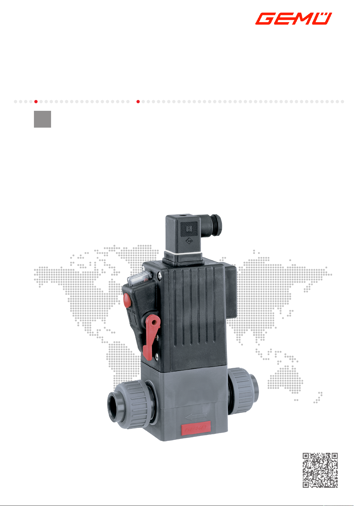
GEMÜ 205
Electrically operated solenoid valve
EN
Operating instructions
further information
webcode: GW-205
Page 2

All rights including copyrights or industrial property rights are expressly reserved.
Keep the document for future reference.
© GEMÜ Gebr. Müller Apparatebau GmbH & Co. KG
01.07.2019
www.gemu-group.com2 / 24GEMÜ 205
Page 3

Contents
1 General information ................................................... 4
1.1 Information ......................................................... 4
1.2 Symbols used ..................................................... 4
1.3 Definition of terms ............................................. 4
1.4 Warning notes .................................................... 4
2 Safety information .................................................... 5
3 Product description ................................................... 5
4 Correct use ................................................................ 6
5 Order data ................................................................. 7
6 Technical data ........................................................... 8
7 Dimensions ............................................................... 9
8 Manufacturer's information ....................................... 12
8.1 Delivery ............................................................... 12
8.2 Transport ............................................................ 12
8.3 Storage ............................................................... 12
8.4 Scope of delivery ................................................ 12
9 Installation in piping .................................................. 12
10 Electrical connection ................................................. 13
11 Commissioning ......................................................... 14
12 Operation .................................................................. 15
13 Inspection and servicing ............................................ 15
14 Error clearance .......................................................... 17
15 Removal from piping ................................................. 18
16 Disposal .................................................................... 18
17 Returns ..................................................................... 18
18 Declaration of Incorporation according to 2006/42/
EC (Machinery Directive) ........................................... 19
19 Declaration of conformity according to 2014/68/EU
(Pressure Equipment Directive) ................................. 20
3 / 24
GEMÜ 205www.gemu-group.com
Page 4
1 General information
SIGNAL WORD
Type and source of the danger
Possible
symbol for
the specific
danger
Possible consequences of non-observance.
Measures for avoiding danger.
1 General information
1.1 Information
– The descriptions and instructions apply to the stand-
ard versions. For special versions not described in this
document the basic information contained herein applies in combination with any additional special documentation.
– Correct installation, operation, maintenance and repair
work ensure faultless operation of the product.
– Should there be any doubts or misunderstandings, the
German version is the authoritative document.
– Contact us at the address on the last page for staff
training information.
1.2 Symbols used
The following symbols are used in this document:
Symbol Meaning
Tasks to be performed
Response(s) to tasks
– Lists
1.3 Definition of terms
Working medium
The medium that flows through the GEMÜ product.
CAUTION
Potentially dangerous situation!
▶ Non-observance can cause moderate
to light injury.
NOTICE
Potentially dangerous situation!
▶ Non-observance can cause damage to
property.
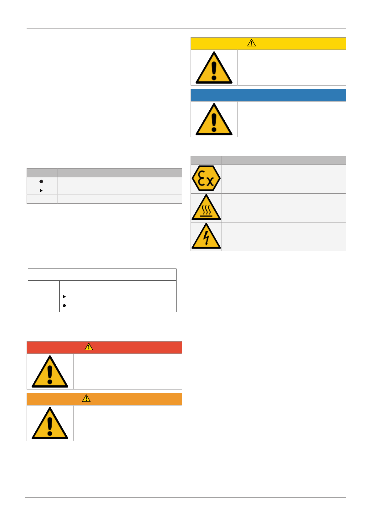
The following symbols for the specific dangers can be used
within a warning note:
Symbol Meaning
Danger of explosion!
Hot plant components!
Risk of electric shock
1.4 Warning notes
Wherever possible, warning notes are organised according to
the following scheme:
Warning notes are always marked with a signal word and
sometimes also with a symbol for the specific danger.
The following signal words and danger levels are used:
DANGER
Imminent danger!
▶ Non-observance can cause death or
severe injury.
WARNING
Potentially dangerous situation!
▶ Non-observance can cause death or
severe injury.
www.gemu-group.com4 / 24GEMÜ 205
Page 5
4
5
1
2
3
3 Product description
2 Safety information
The safety information in this document refers only to an individual product. Potentially dangerous conditions can arise
in combination with other plant components, which need to
be considered on the basis of a risk analysis. The operator is
responsible for the production of the risk analysis and for
compliance with the resulting precautionary measures and
regional safety regulations.
The document contains fundamental safety information that
must be observed during commissioning, operation and
maintenance. Non-compliance with these instructions may
cause:
– Personal hazard due to electrical, mechanical and
chemical effects.
– Hazard to nearby equipment.
– Failure of important functions.
– Hazard to the environment due to the leakage of dan-
gerous materials.
The safety information does not take into account:
– Unexpected incidents and events, which may occur
during installation, operation and maintenance.
– Local safety regulations which must be adhered to by
the operator and by any additional installation person-
nel.
Prior to commissioning:
1. Transport and store the product correctly.
2. Do not paint the bolts and plastic parts of the product.
3. Carry out installation and commissioning using trained
personnel.
4. Provide adequate training for installation and operating
personnel.
5. Ensure that the contents of the document have been fully
understood by the responsible personnel.
6. Define the areas of responsibility.
7. Observe the safety data sheets.
8. Observe the safety regulations for the media used.
During operation:
9. Keep this document available at the place of use.
10. Observe the safety information.
11. Operate the product in accordance with this document.
12. Operate the product in accordance with the specifications.
13. Maintain the product correctly.
14. Do not carry out any maintenance work and repairs not
described in this document without consulting the manufacturer first.
3 Product description
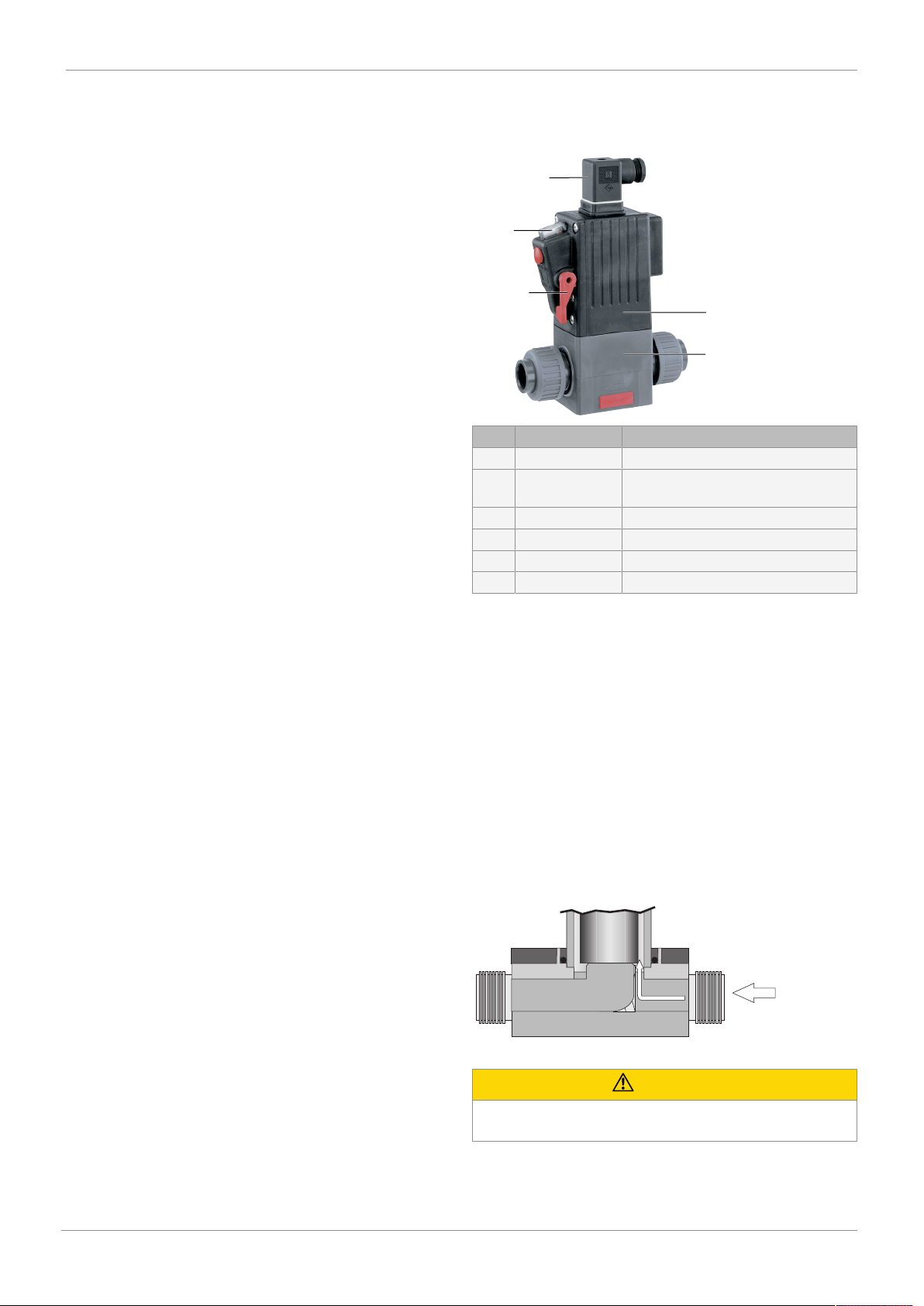
3.1 Construction
Item Name Materials
1 Plug PA
2 Optical position
indicator
3 Manual override PBT
4 Valve housing PBT
5 Valve body PVC-U, grey or PVDF
Seal materials FPM, PTFE or EPDM
3.2 Description
The GEMÜ 205 directly controlled 2/2-way plastic solenoid
valve has a high performance coil. It is hermetically separated from the medium by means of a flexible PTFE bush. The
armature is sealed by a bellows made of PTFE backed by an
additional safety diaphragm. The plug has a rectifier for use
with an AC supply. A manual override and an optical position
indicator are integrated as standard.
3.3 Function
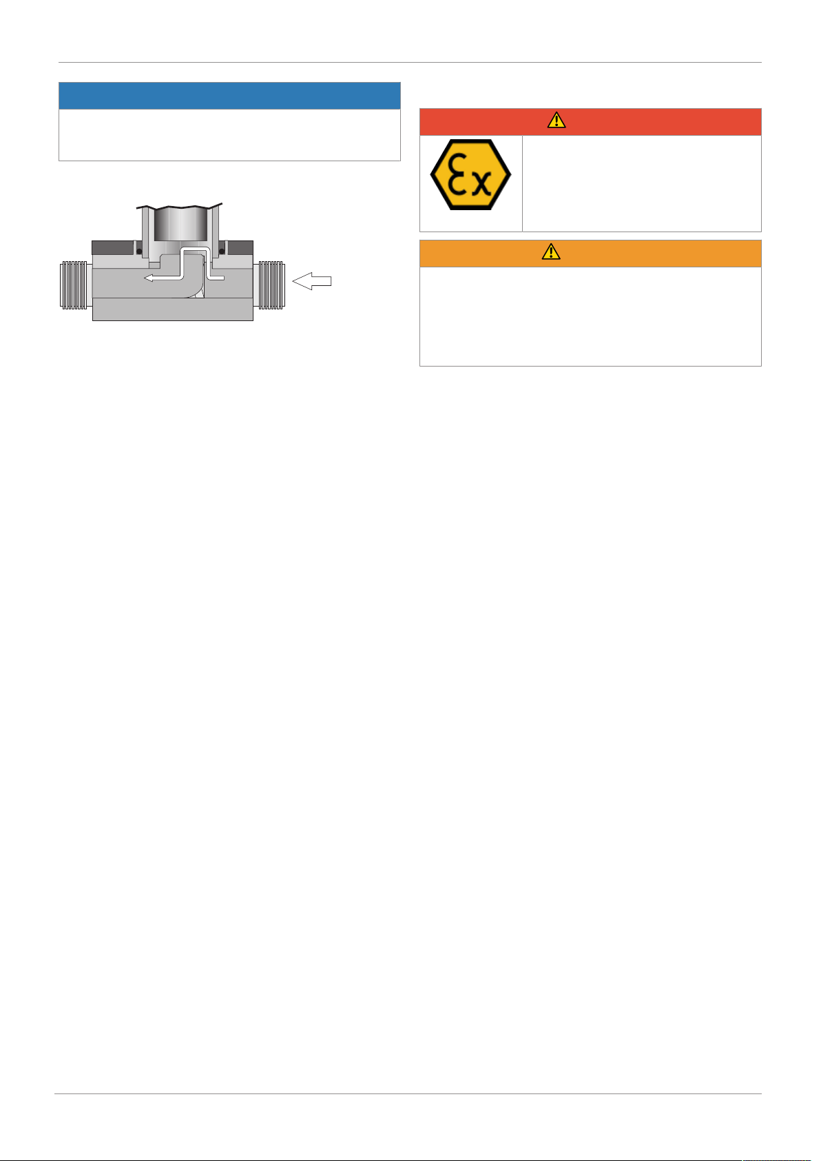
The GEMÜ 205 directly controlled 2/2-way solenoid valve is
designed for controlling media.
When the valve is closed the medium flows into the valve
body and presses onto the piston. The valve remains closed.
Observe the permissible operating pressure (see “Technical
data“, page8).
PVC
In cases of uncertainty:
15. Consult the nearest GEMÜ sales office.
Fig.1: Valve CLOSED
CAUTION
www.gemu-group.com 5 / 24 GEMÜ 205
Operating pressure too high
▶ Damage to the solenoid / destruction of the solenoid.
Page 6
4 Correct use
NOTICE
Operating pressure too high
▶ The valve cannot be opened electromagnetically if the
operating pressure is too high.
When voltage is applied the solenoid in the valve actuator is
activated and lifts the armature. This opens the valve outlet.
Fig.2: Valve OPEN
4 Correct use
DANGER
Danger of explosion!
▶ Risk of severe injury or death.
● Only versions that have been ap-
proved according to their technical
data may be used in potentially explosive environments.
WARNING
Improper use of the product!
▶ Risk of severe injury or death.
▶ Manufacturer liability and guarantee will be void.
● Only use the product in accordance with the operating
conditions specified in the contract documentation and
this document.
The product is designed for installation in piping systems
and for controlling a working medium.
1. Use the product in accordance with the technical data.
2. Protect the product from direct weathering.
www.gemu-group.com6 / 24GEMÜ 205
Page 7
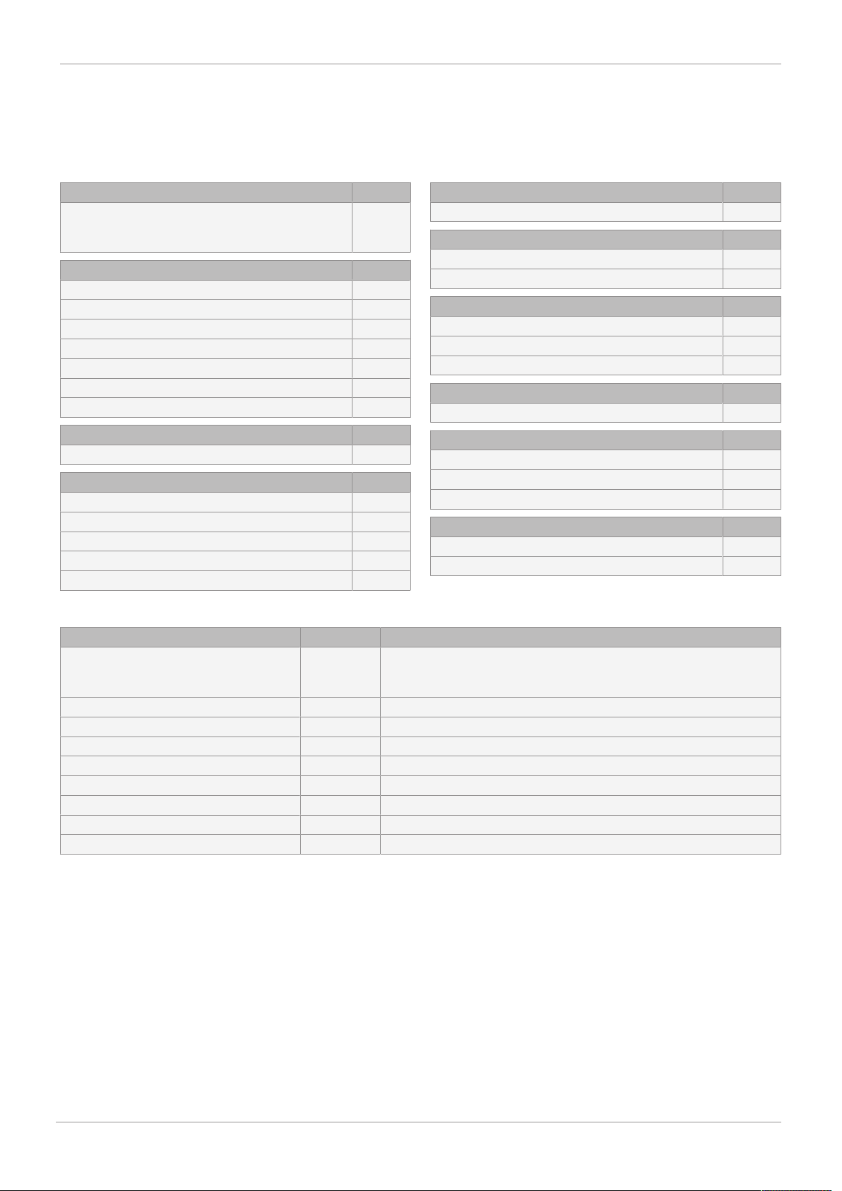
5 Order data
The order data provide an overview of standard configurations.
Please check the availability before ordering. Other configurations available on request.
Order codes
5 Order data
1 Type Code
Solenoid valve, directly controlled,
optical position indicator,
manual override
2 DN Code
DN 10 10
DN 15 15
DN 20 20
DN 25 25
DN 32 32
DN 40 40
DN 50 50
3 Body configuration Code
2/2-way body D
4 Connection type Code
Spigot DIN 0
Threaded socket DIN ISO 228 1
Solvent cement socket DIN 2
Union end with DIN insert (socket) 7
Spigot - inch 30
205
4 Connection type Code
Threaded socket NPT 31
5 Valve body material Code
PVC-U, grey 1
PVDF 20
6 Seal material Code
FPM 4
PTFE 5
EPDM 14
7 Control function Code
Normally closed (NC) 1
8 Voltage Code
24 V 24
120 V 120
230 V 230
9 Frequency Code
DC DC
50 - 60 Hz 50/60
Order example
Order option Code Description
1 Type 205 Solenoid valve, directly controlled,
optical position indicator,
manual override
2 DN 15 DN 15
3 Body configuration D 2/2-way body
4 Connection type 0 Spigot DIN
5 Valve body material 1 PVC-U, grey
6 Seal material 5 PTFE
7 Control function 1 Normally closed (NC)
8 Voltage 230 230 V
9 Frequency 50/60 50 - 60 Hz
www.gemu-group.com
7 / 24
GEMÜ 205
Page 8
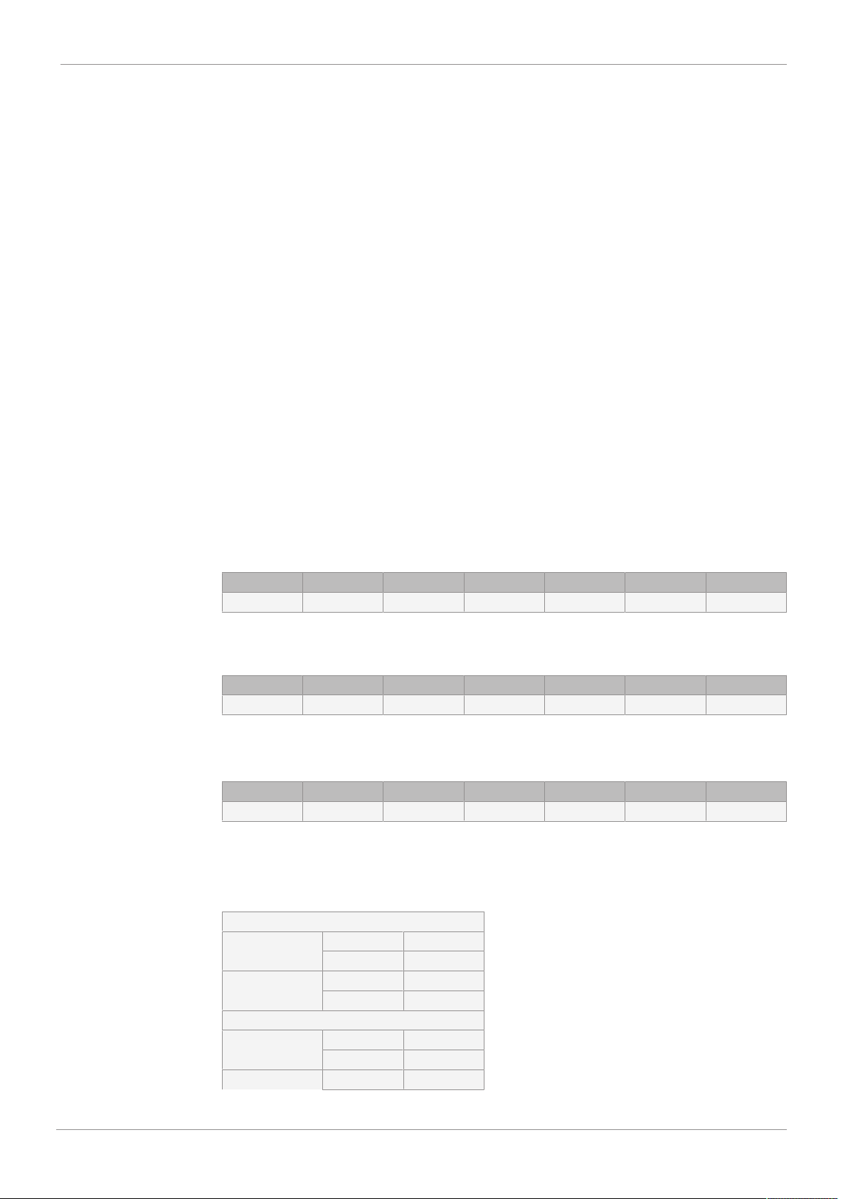
6 Technical data
6 Technical data
6.1 Medium
Working medium: Corrosive, inert, gaseous and liquid media which have no negative impact on the physical and
chemical properties of the body and seal material.
6.2 Temperature
Media temperature: PVC-U, grey (code 1): 10 to 60 °C
PVDF (code 20): -20 to 100 °C
Ambient temperature: 10 to 40 °C
Storage temperature: 0 to 40 °C
6.3 Product compliance
Machinery Directive: 2006/42/EC
Low Voltage
Directive:
EMC Directive: 2014/30/EU
2014/35/EU
Technical standards used:
EN 55011:1991 (150 kHz to 30 MHz)
EN 55014:1993 (148.5 kHz to 30 MHz)
6.4 Mechanical data
Protection class: IP 65
Weight:
DN 10 DN 15 DN 20 DN 25 DN 32 DN 40 DN 50
0.85 0.9 0.9 2.8 2.8 3.6 3.6
Weights in kg
6.5 Pressure
Operating pressure:
Kv values:
DN 10 DN 15 DN 20 DN 25 DN 32* DN 40 DN 50
0 - 6.0 0 - 2.0 0 - 1.0 0 - 1.0 0 - 1.0 0 - 0.2 0 - 0.2
* 24 V DC: 0 – 0.5 bar
All pressures are gauge pressures.
Nominal size corresponds to valve seat diameter.
DN 10 DN 15 DN 20 DN 25 DN 32 DN 40 DN 50
0.8 1.8 2.3 6.0 7.5 9.5 12.5
6.6 Electrical data
Power consumption:
GEMÜ 205
Kv values in m³/h
AC operation
Pull in DN 10 - 20 125 VA
DN 25 - 50 400 VA
Hold in DN 10 - 20 12 VA
DN 25 - 50 30 VA
DC operation
Pull in DN 10 - 20 35 W
DN 25 - 50 70 W
Hold in DN 10 - 20 7 W
8 / 24
www.gemu-group.com
Page 9
C
B
F
A
Plug rotatable 90°
H1
H
L
C
ød
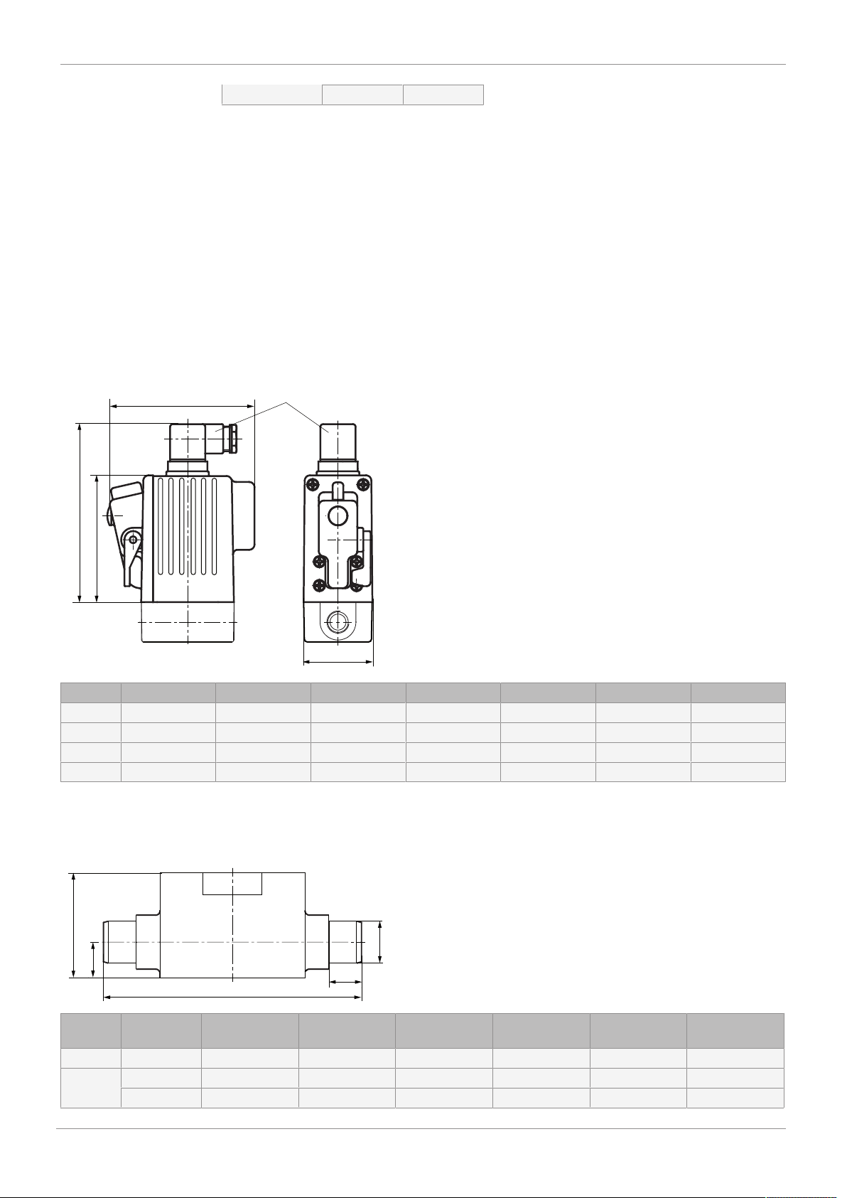
7 Dimensions
Power consumption:
Permissible voltage
±10 % to VDE 0580
DN 25 - 50 18 W
tolerance:
Duty cycle: Continuous duty
Wiring note: Special wiring on request. When using electronic switches and additional wiring, carefully design
out any potential residual currents upon installation.
Installation note: Please note: The DC solenoid is designed for unsmoothed voltages, e.g. as obtained from a bridge
rectifier.
7 Dimensions
7.1 Actuator
DN 10 DN 15 DN 20 DN 25 DN 32 DN 40 DN 50
A 134 134 134 167 167 196 196
B 100 100 100 128 128 157 157
C 110 110 110 144 144 158 158
F 52 52 52 88 88 110 110
Dimensions in mm
7.2 Body dimensions
7.2.1 Solvent cement spigot (code 0, 30)
Connection
C 16 19 22 26 31 39
Code
1)
ød 0 20 25 32 40 50 63
30 21.3 26.7 33.4 - - -
DN 15 DN 20 DN 25 DN 32 DN 40 DN 50
9 / 24
GEMÜ 205www.gemu-group.com
Page 10
G 3/8
3/8"-18 NPT
70
15
30
15
70
14
16
30
H
H1
G
LB
LA
ød
øD
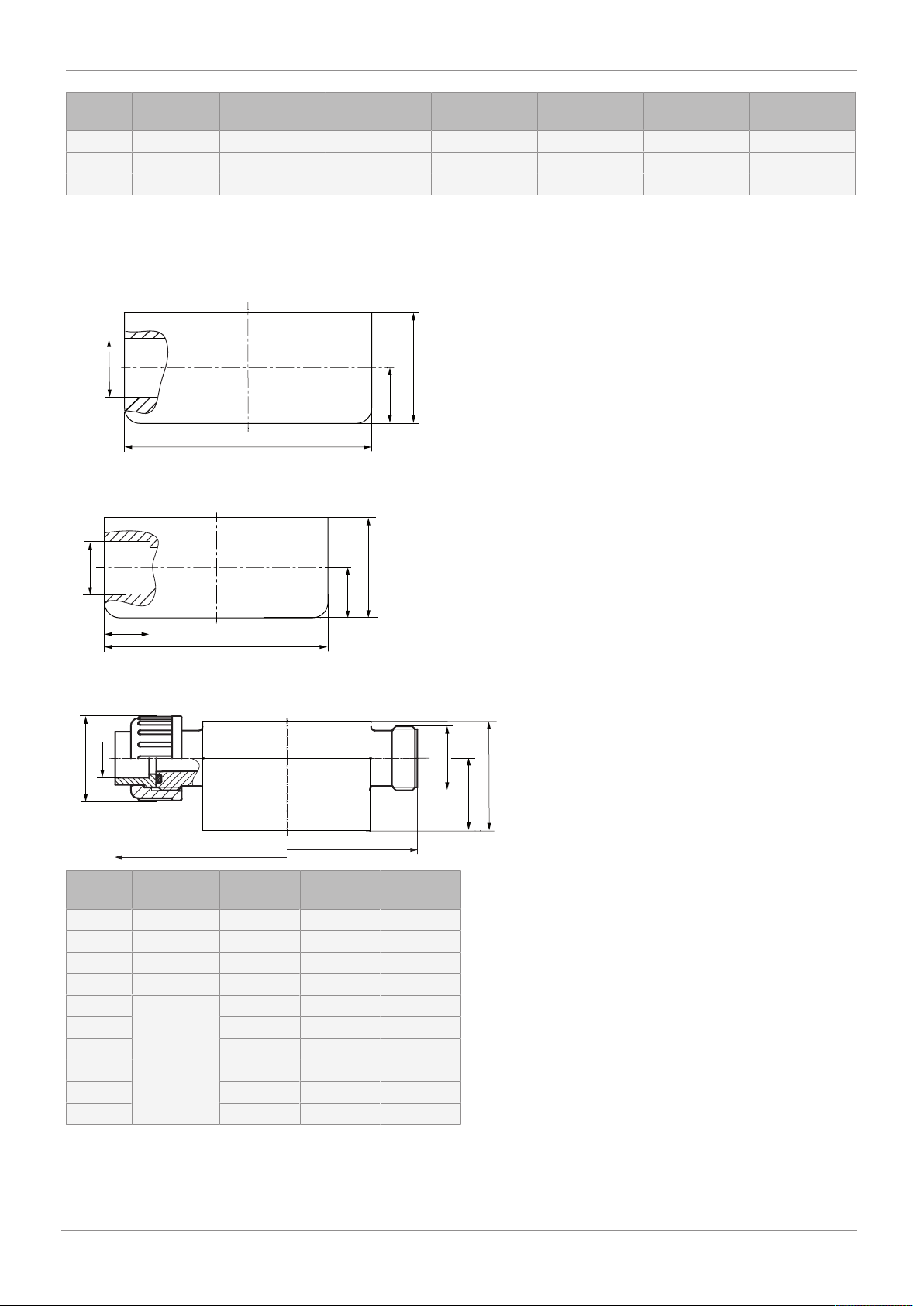
7 Dimensions
Connection
Code
1)
DN 15 DN 20 DN 25 DN 32 DN 40 DN 50
H 50 50 72 72 85 85
H1 17 17 24 24 34 34
L 124 144 154 174 194 224
Dimensions in mm
1) Connection type
Code 0: Spigot DIN
Code 30: Spigot - inch
7.2.2 Threaded socket (code 1, 31)
Dimensions in mm
7.2.3 Solvent cement socket (code 2)
Dimensions in mm
7.2.4 Union end with insert (code 7)
Material
1)
Code
DN 10 DN 15 DN 20
ø d 16 20 25
ø d G 3/4 G 1 G 1 1/4
H 45 63 63
H1 30 30 30
øD 1 35 43 53
LA 108 108 108
LB 142 146 152
øD 20 34 47 57
LA 106 106 106
LB 142 144 148
Dimensions in mm
1) Valve body material
Code 1: PVC-U, grey
Code 20: PVDF
GEMÜ 205
10 / 24
www.gemu-group.com
Page 11
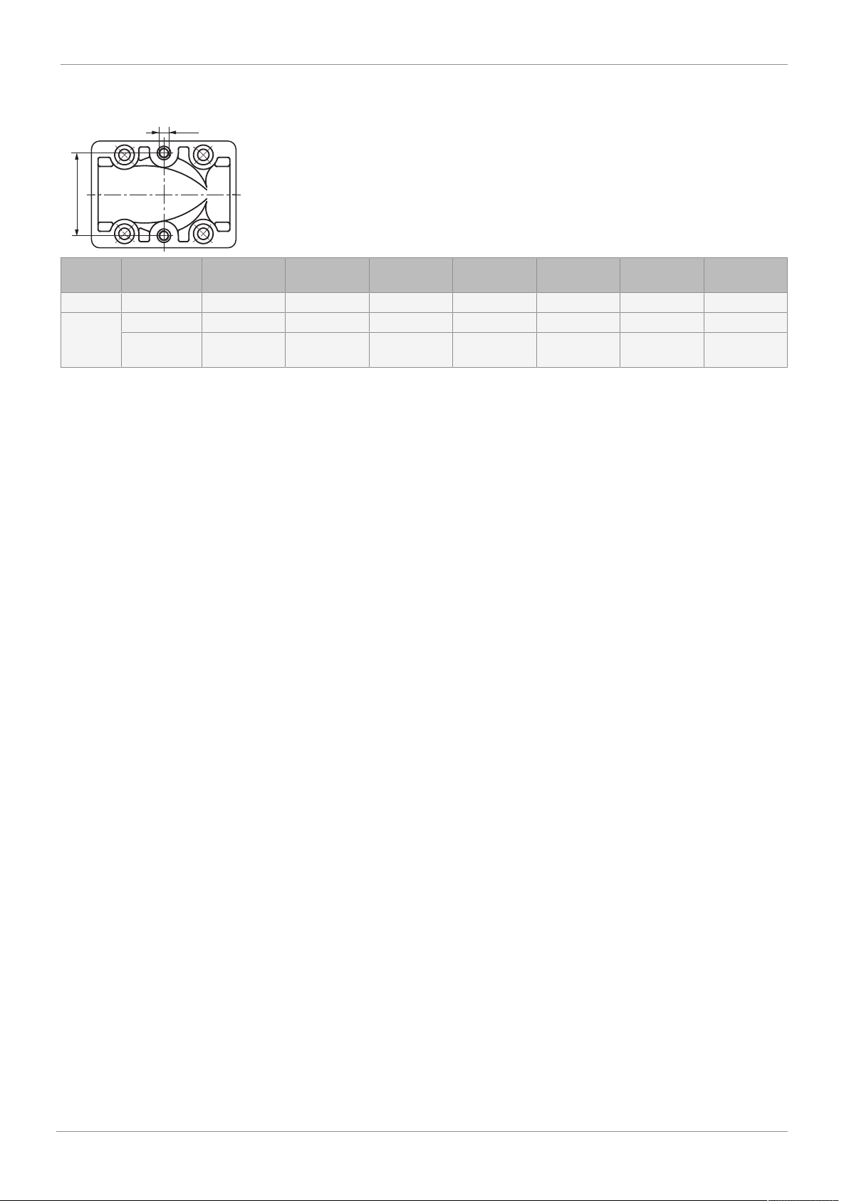
7.3 Mounting dimensions
G
E
7 Dimensions
Connection
Code
1)
DN 10 DN 15 DN 20 DN 25 DN 32 DN 40 DN 50
E 40 40 40 44.5 44.5 44.5 44.5
G 0,1,2,7 M5 M5 M5 M8 M8 M8 M8
30,31 8 - 36 UNF 10 - 32 UNF 10 - 32 UNF 5/16” - 32
- - -
UNF
Dimensions in mm
1) Connection type
Code 0: Spigot DIN
Code 1: Threaded socket DIN ISO 228
Code 2: Solvent cement socket DIN
Code 7: Union end with DIN insert (socket)
Code 30: Spigot - inch
Code 31: Threaded socket NPT
11 / 24
GEMÜ 205www.gemu-group.com
Page 12
8 Manufacturer's information
1 212
8 Manufacturer's information
8.1 Delivery
● Check that all parts are present and check for any damage immediately upon receipt.
The product's performance is tested at the factory. The
scope of delivery is apparent from the dispatch documents
and the design from the order number.
8.2 Transport
1. Only transport the product by suitable means. Do not
drop. Handle carefully.
2. After the installation dispose of transport packing material according to relevant local or national disposal regulations / environmental protection laws.
8.3 Storage
1. Store the product free from dust and moisture in its original packaging.
2. Avoid UV rays and direct sunlight.
3. Do not exceed the maximum storage temperature (see
chapter "Technical data").
4. Do not store solvents, chemicals, acids, fuels or similar
fluids in the same room as GEMÜ products and their
spare parts.
8.4 Scope of delivery
The following is included in the scope of delivery:
– Solenoid valve with solenoid coil
– Plug
– Installation, operating and maintenance instructions
9.1 Installation with solvent cement sockets
CAUTION
Wrong solvent cement
▶ Valve body will be damaged.
● Only use solvent cement suitable for the valve body.
NOTICE
▶ The solvent cement is not included in the scope of deliv-
ery.
● Only use suitable solvent cement!
1. Apply solvent cement inside the valve body socket connections and on the piping as specified by the solvent cement manufacturer.
2. Solvent cement the valve body to the piping.
9.2 Installation with solvent cement spigots
CAUTION
Wrong solvent cement
▶ Valve body will be damaged.
● Only use solvent cement suitable for the valve body.
NOTICE
▶ The solvent cement is not included in the scope of deliv-
ery.
● Only use suitable solvent cement!
9 Installation in piping
WARNING
The equipment is subject to pressure!
▶ Risk of severe injury or death.
● Depressurize the plant.
● Completely drain the plant.
CAUTION
Hot plant components!
▶ Risk of burns!
● Only work on plant that has cooled
down.
CAUTION
Operating pressure to high or working medium temperature
too high
▶ Damage to the valve body
● Only install the solenoid valve in aligned pipes in order to
avoid stresses in the valve body.
● Do not exceed the permissible operating pressure.
● Do not exceed the permissible temperature of the work-
ing medium.
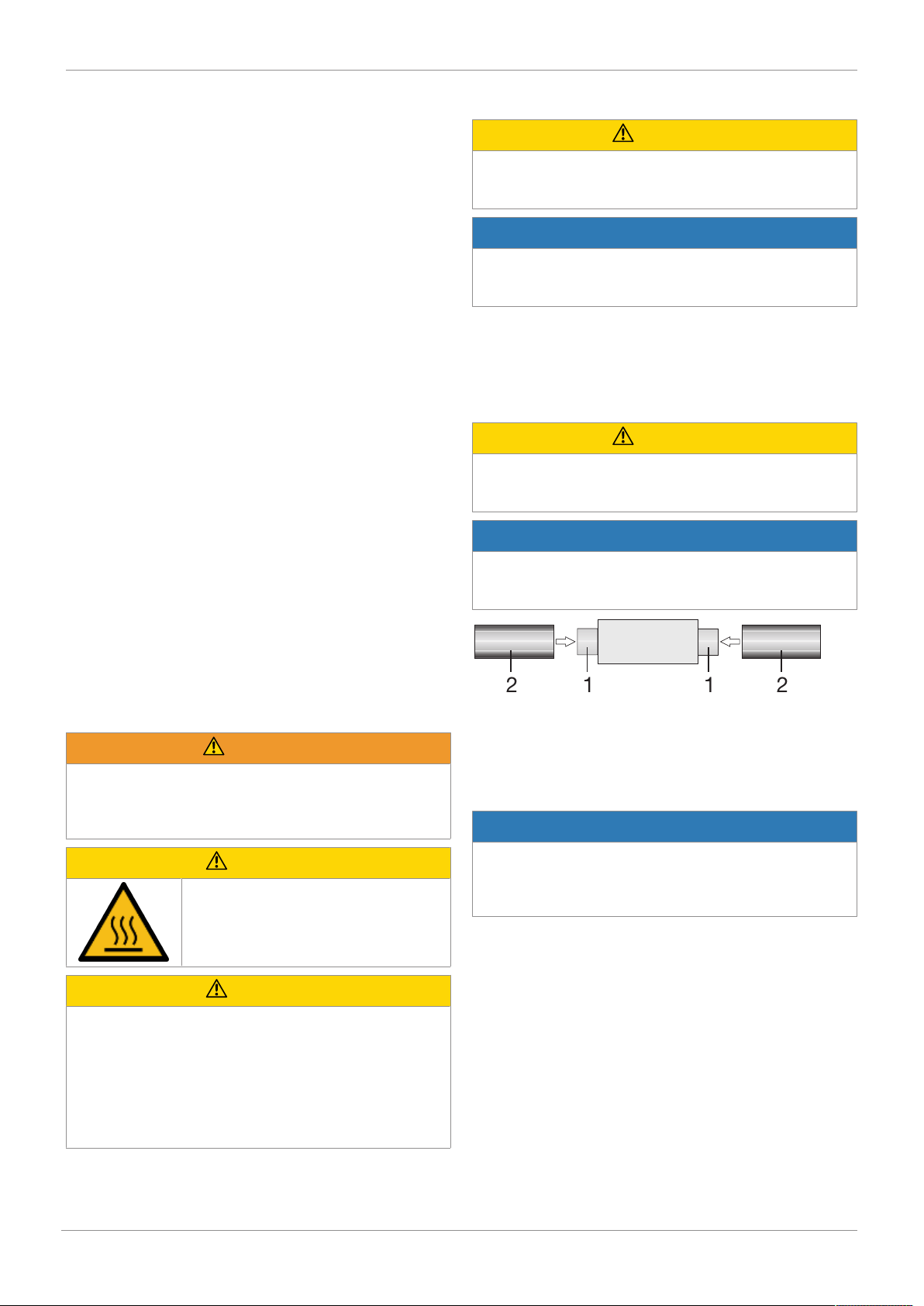
1. Apply solvent cement on the outside of the valve body
spigots 1 and on the inside of the piping connector 2 as
specified by the solvent cement manufacturer.
2. Connect the valve body to the piping.
9.3 Installation with threaded sockets
NOTICE
Thread sealant
▶ The thread sealant is not included in the scope of deliv-
ery.
● Only use appropriate thread sealant.
● Screw the threaded connections into the piping in accord-
ance with valid standards.
www.gemu-group.com12 / 24GEMÜ 205
Page 13
12
3
5 1 4
2
3
1
2
3
4
1
2
Supply voltage
10 Electrical connection
9.4 Installation with union ends
CAUTION
Do not use the solenoid coil as a lever
▶ If the solenoid coil is used as a lever, the solenoid coil
and bush could be destroyed.
● Use only the spanner flats provided to screw the solen-
oid valve to the piping.
CAUTION
Welding!
▶ Damage to the valve actuator or valve body.
● Observe welding standards.
CAUTION
Wrong solvent cement
▶ Valve body will be damaged.
● Only use solvent cement suitable for the valve body.
NOTICE
▶ The solvent cement is not included in the scope of deliv-
ery.
● Only use suitable solvent cement!
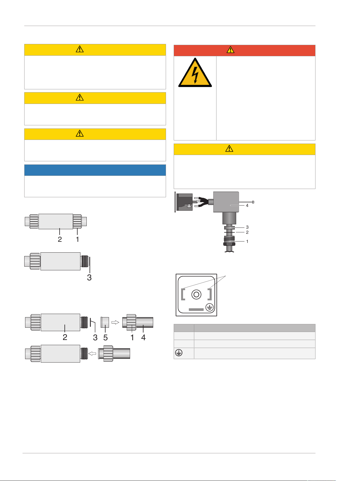
1. Push the union nut 1 over the piping 4. Connect the insert
5 with the piping 4 by cementing / welding.
10 Electrical connection
DANGER
Risk of electric shock
▶ Risk of injury or death (if operating
voltage is higher than safe extra low
voltage).
▶ Electric shock can cause severe burns
and fatal injury.
● Work on electrical connections only by
qualified trained personnel.
● Disconnect the cable from the power
supply before making the electrical
connection.
● Connect the protective earth con-
ductor.
CAUTION
AC voltage
▶ Solenoid valve will be destroyed by wrong plug.
● Solenoid valves used with AC voltage may only be oper-
ated with a plug with a built-in rectifier (only up to
DN20).
2. Unscrew union nut 1 from valve body 2.
3. Reinsert O-ring 3 if necessary.
4. Screw the union nut 1 to the valve body 2 again.
5. Connect the other side of the valve body 2 to the piping 4,
too.
1. Insert the cable through the locking screw 1, the pressure
ring 2, the seal 3 and the housing of the plug 4.
Item Name
1 Supply voltage
2 Supply voltage
Protective earth conductor (PE)
2. Connect the cable to the relevant terminals on the terminal block.
3. Push the terminal block into the housing of the plug (acc.
to DIN EN 175301-803, previously DIN 43650) until it audibly clicks in position.
4. Ensure that the cable is not caught.
5. Tighten the locking screw on the plug.
www.gemu-group.com 13 / 24 GEMÜ 205
Page 14
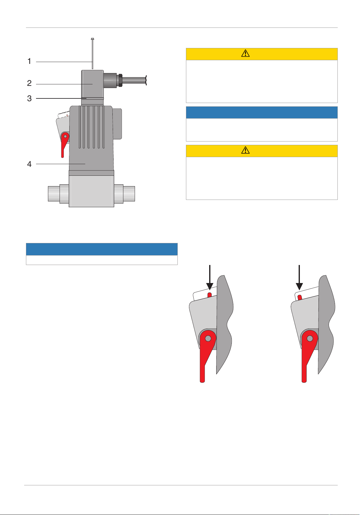
11 Commissioning
1
2
3
4
Valve closed
Valve open
6. Push the plug 2 and the gasket 3 onto the valve actuator
4.
7. Tighten the fixing screw 1 with a torque of approx. 0.6
Nm.
NOTICE
▶ If the torque is too high the thread may be stripped.
11 Commissioning
CAUTION
Medium flowing out
▶ Danger from medium flowing out.
● Before commissioning make sure that there is no danger
from medium flowing out.
● Before commissioning check the tightness of the media
connections.
NOTICE
Operating pressure too high
▶ The valve cannot be opened electromagnetically if the
operating pressure is too high.
CAUTION
Foreign matter
▶ Damage to the valves.
● If the plant is new and after repairs, rinse the piping sys-
tem with the valves fully open.
ð The plant operator is responsible for selecting the clean-
ing material and performing the procedure.
1. Make sure that the operating voltage corresponds with
the permissible valve voltage.
2. Make sure that the unit is installed properly.
3. Check the function of the solenoid valve.
4. Check the tightness of the media connections and the
solenoid valve itself.
11.1 Optical position indicator
www.gemu-group.com14 / 24GEMÜ 205
Page 15
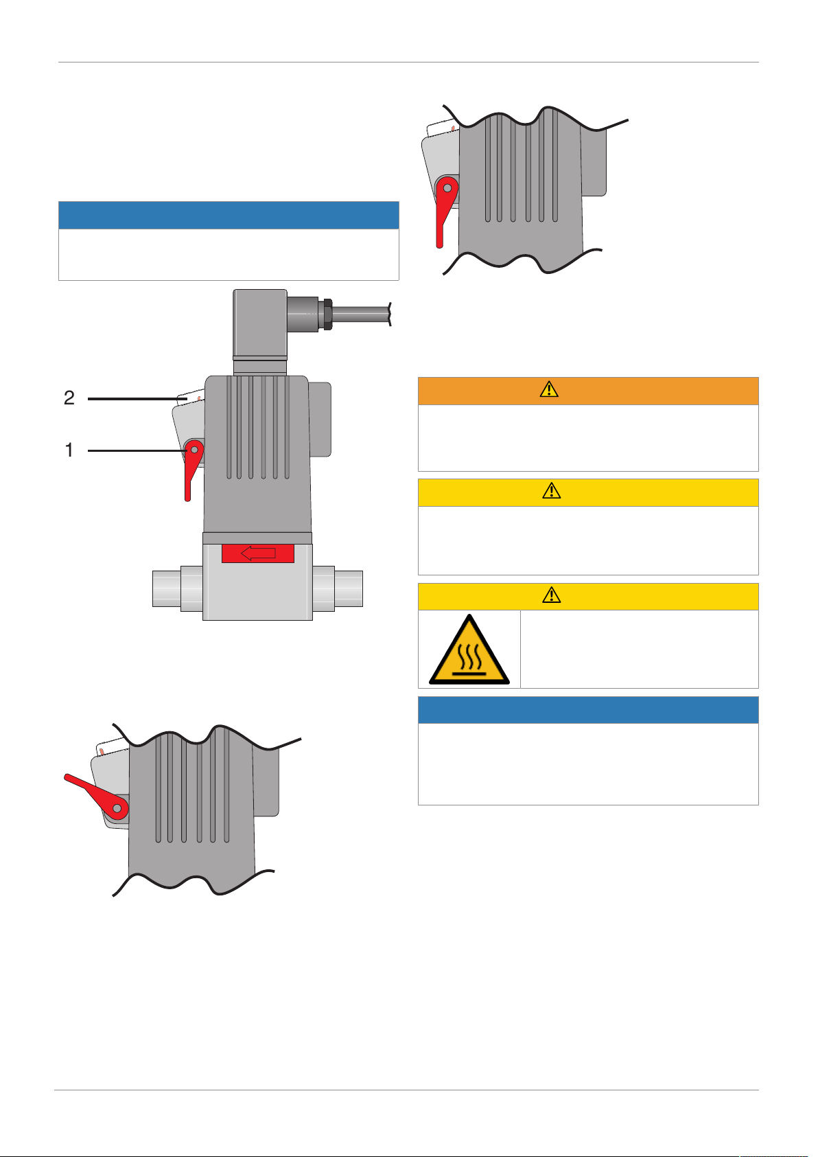
1
2
13 Inspection and servicing
12 Operation
12.1 Normal operation
During normal operation there is no need for adjustments at
the valve.
12.2 Emergency operation via manual override
NOTICE
Manual override
▶ Only actuate the manual override in case of malfunction
(currentless)!
Close the valve via manual override (currentless)
2. Turn the lever downwards.
ð The indicator of the optical position indicator moves to-
wards the valve actuator.
13 Inspection and servicing
WARNING
The equipment is subject to pressure!
▶ Risk of severe injury or death.
● Depressurize the plant.
● Completely drain the plant.
The solenoid valve is equipped with a manual override 1 and
an optical position indicator 2.
Open the valve via manual override (currentless)
1. Turn the lever upwards.
ð The indicator of the optical position indicator moves away
from the valve actuator.
CAUTION
Use of incorrect spare parts!
▶ Damage to the GEMÜ product.
▶ Manufacturer liability and guarantee will be void.
● Use only genuine parts from GEMÜ.
CAUTION
Hot plant components!
▶ Risk of burns!
● Only work on plant that has cooled
down.
NOTICE
Exceptional maintenance work!
▶ Damage to the GEMÜ product.
● Any maintenance work and repairs not described in
these operating instructions must not be performed
without consulting the manufacturer first.
The operator must carry out regular visual examination of the
GEMÜ products depending on the operating conditions and
the potential danger in order to prevent leakage and damage.
The product also must be disassembled and checked for
wear in the corresponding intervals.
1. Have servicing and maintenance work performed by
trained personnel.
2. Wear appropriate protective gear as specified in plant operator's guidelines.
3. Shut off plant or plant component.
4. Secure plant or plant component against recommissioning.
5. Depressurize the plant or plant component.
6. Actuate GEMÜ products which are always in the same
position four times a year.
www.gemu-group.com 15 / 24 GEMÜ 205
Page 16
13 Inspection and servicing
1
2
5
4
6
3
13.1 Cleaning the product
CAUTION
Foreign matter
▶ Damage to the valves.
● If the plant is new and after repairs, rinse the piping sys-
tem with the valves fully open.
ð The plant operator is responsible for selecting the clean-
ing material and performing the procedure.
– Clean the product with a damp cloth.
– Do not clean the product with a high pressure clean-
ing device.
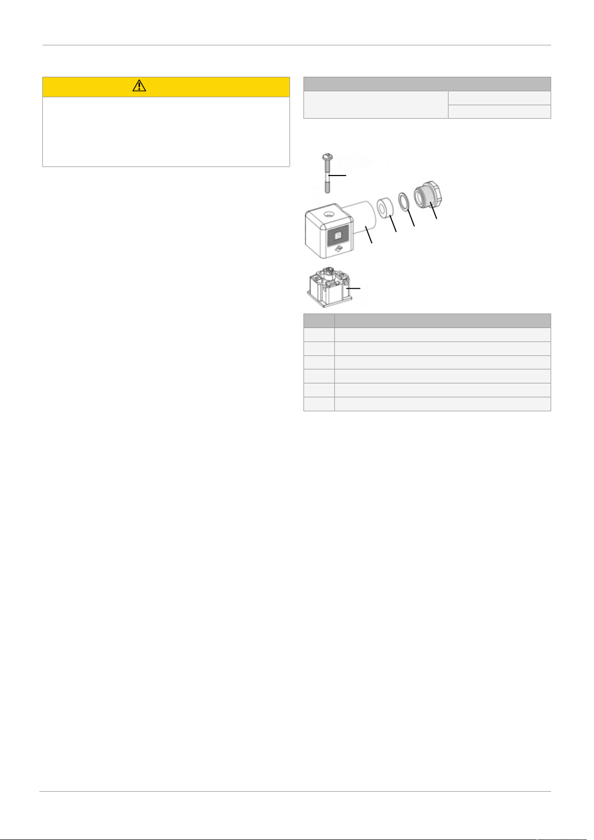
13.2 Spare parts
Spare parts
Plugs GEMÜ 1220
GEMÜ 1221
Order number on request
Item Name
1 Screw
2 Plug
3 Terminal block
4 Pressure ring
5 Gasket
6 Cable entry
www.gemu-group.com16 / 24GEMÜ 205
Page 17

14 Error clearance
14 Error clearance
Error Error cause Error clearance
No function No power supply Check power supply and connection with
product label
Solenoid coil faulty Replace solenoid valve
Plug wrongly connected Check connection of plug and correct if
necessary
Operating pressure too high Check operating pressure, reduce if
necessary
PTFE bush leaking Replace solenoid valve
Armature blocked Replace solenoid valve
Solenoid valve leaking Valve seat leaking Replace solenoid valve
Solenoid valve does not close Manual override engaged/actuated Check the position of the manual
override and close if necessary
www.gemu-group.com
17 / 24
GEMÜ 205
Page 18
15 Removal from piping
15 Removal from piping
WARNING
The equipment is subject to pressure!
▶ Risk of severe injury or death.
● Depressurize the plant.
● Completely drain the plant.
CAUTION
Hot plant components!
▶ Risk of burns!
● Only work on plant that has cooled
down.
1. Allow the plant to cool down.
2. Allow the plant to run empty.
3. Unscrew the electrical wiring.
4. Remove the product from the piping with appropriate
measures
16 Disposal
1. Pay attention to adhered residual material and gas diffusion from penetrated media.
2. Dispose of all parts in accordance with the disposal regulations/environmental protection laws.
17 Returns
Legal regulations for the protection of the environment and
personnel require that the completed and signed return delivery note is included with the dispatch documents. Returned
goods can be processed only when this note is completed. If
no return delivery note is included with the product, GEMÜ
cannot process credits or repair work but will dispose of the
goods at the operator's expense.
1. Clean the product.
2. Request a return delivery note from GEMÜ.
3. Complete the return delivery note.
4. Send the product with a completed return delivery note to
GEMÜ.
www.gemu-group.com18 / 24GEMÜ 205
Page 19

18 Declaration of Incorporation according to 2006/42/EC (Machinery Directive)
18 Declaration of Incorporation according to 2006/42/EC (Machinery Directive)
Declaration of Incorporation
according to the EC Machinery Directive 2006/42/EC, Annex II, 1.B for
partly completed machinery
We, GEMÜ Gebr. Müller Apparatebau GmbH & Co. KG
Fritz-Müller-Straße 6-8
74653 Ingelfingen-Criesbach, Germany
declare that the following product
Make: GEMÜ
Serial number: from 29.12.2009
Project number: Type 205
Commercial name: GEMÜ 205
meets the following essential requirements of the Machinery Directive 2006/42/EC:
1.1.5.; 1.2.1.; 1.3.; 1.3.2.; 1.3.9.; 1.5.1.; 1.5.16.; 1.5.2.; 1.5.5.; 1.5.6.; 1.5.7.; 1.6.3.; 4.1.2.1.; 4.1.2.3.; 4.1.2.4.; 4.1.2.5.; 4.1.2.6. a);
4.1.2.6. c); 4.1.2.6. e); 4.1.3.; 4.2.1.4.; 4.2.2.; 4.2.3.; 4.3.1.; 4.3.2.; 4.3.3.; 4.4.1.; 4.4.2.; 5.3.; 5.4.; 6.1.1.
We also declare that the specific technical documentation has been compiled in accordance with part B of Annex VII.
The manufacturer or his authorised representative undertake to transmit, in response to a reasoned request by the national
authorities, relevant information on the partly completed machinery. This transmission takes place:
Electronically
Authorised documentation officer GEMÜ Gebr. Müller Apparatebau GmbH & Co. KG
Fritz-Müller-Straße 6-8
74653 Ingelfingen, Germany
This does not affect the industrial property rights!
Important note! The partly completed machinery may be put into service only if it was determined, where appropriate, that the
machinery into which the partly completed machinery is to be installed meets the provisions of this Directive.
Ingelfingen-Criesbach 29-05-2018
Joachim Brien
Head of Technical Department
19 / 24
GEMÜ 205www.gemu-group.com
Page 20

19 Declaration of conformity according to 2014/68/EU (Pressure Equipment Directive)
19 Declaration of conformity according to 2014/68/EU (Pressure Equipment Directive)
EU Declaration of Conformity
in accordance with 2014/68/EU (Pressure Equipment Directive)
We, GEMÜ Gebr. Müller Apparatebau GmbH & Co. KG
Fritz-Müller-Straße 6-8
74653 Ingelfingen-Criesbach, Germany
declare that the product listed below complies with the safety requirements of the Pressure Equipment Directive 2014/68/EU.
Description of the pressure equipment: GEMÜ205
Notified body: TÜV Rheinland Industrie Service GmbH
Number: 0035
Certificate no.: 01 202 926/Q-02 0036
Conformity assessment procedure: Module H
Technical standard used: AD 2000
Note for products with a nominal size ≤ DN 25:
The products are developed and produced according to GEMÜ process instructions and quality standards which comply with
the requirements of ISO 9001 and ISO 14001.
According to Article 4, Paragraph 3 of the Pressure Equipment Directive 2014/68/EU these products must not be identified by
a CE-label.
Ingelfingen-Criesbach 29-05-2018
Joachim Brien
Head of Technical Department
GEMÜ 205
20 / 24
www.gemu-group.com
Page 21

www.gemu-group.com 21 / 24 GEMÜ 205
Page 22

www.gemu-group.com22 / 24GEMÜ 205
Page 23

www.gemu-group.com 23 / 24 GEMÜ 205
Page 24
GEMÜ Gebr. Müller Apparatebau GmbH & Co. KG
Fritz-Müller-Straße 6-8, 74653 Ingelfingen-Criesbach,
Germany
Tel. +49 (0)7940 123-0 · [email protected]
www.gemu-group.com
Subject to alteration
07.2019 | 88593456
*88593456*
 Loading...