

Page 1

Professional Mixer
Mezclador para el profesional
Operations Manual
English.................................................................Page 2
Manual de funcionamiento
Español...............................................................Page 4
Page 1
Page 2
27
22
9
21
20
8
8
7
7
6
5
5
4
4
18
26
25
23
3
3
2
2
24
17
16
15 19
14
23
13
1
12
Page 2
11
10
Page 3
Introduction
Congratulations on purchasing the Brand X by Gemini XDJ-19 mixer.
This state of the art mixer is backed by a three year warranty, excluding
crossfader and channel slides. Prior to use, we suggest that you
carefully read all the instructions.
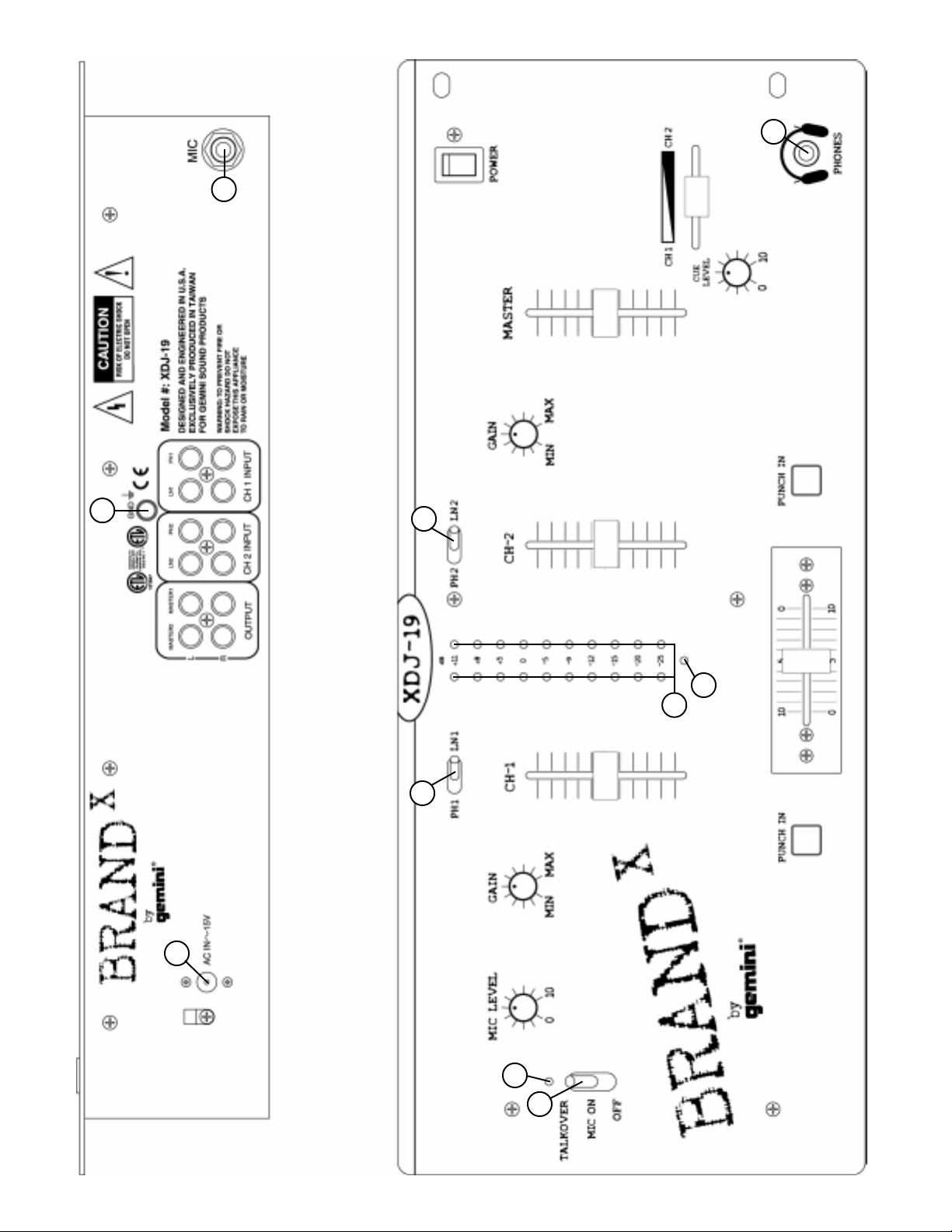
Features
• 2 Stereo Channels
• 2 Phono, 2 Line and 1 Mic Input
• Gain Controls
• Punch In
• Talkover and Level Control for the Mic
• 2 Sets of Master Outputs
• Cue Section with Level Control
Cautions
1. All operating instructions should be read before using this
equipment.
2. To reduce the risk of electrical shock, do not open the unit. There are
NO USER REPLACEABLE PARTS INSIDE. Please refer servicing to a
qualified service technician.
In the U.S.A., if you have any problems with this unit,
call 1-732-738-9003 for customer service. Do not return
equipment to your dealer.
3. Do not expose this unit to direct sunlight or to a heat source such as
a radiator or stove.
4. This unit should be cleaned only with a damp cloth. Avoid solvents
or other cleaning detergents.
5. When moving this equipment, it should be placed in its original carton
and packaging. This will reduce the risk of damage during transit.
6. DO NOT EXPOSE THIS UNIT TO RAIN OR MOISTURE.
7. DO NOT USE ANY SPRAY CLEANER OR LUBRICANT ON ANY
CONTROLS OR SWITCHES.
5. Headphones can be plugged into the front panel mounted
HEADPHONE (27) jack.
Operation
1. POWER ON: Once you have made all the equipment connections to
your mixer, press the POWER (22) switch. The power will turn on
and the POWER LED (17) will glow RED.
2. CHANNEL 1: The GAIN (13) control allows you to individually adjust
the gain of the channel. Switch # (14) allows you to select the
PHONO 1 (8) or the LINE 1 (7) input. The CHANNEL SLIDE (15)
controls the input level of this channel.
3. CHANNEL 2: The GAIN (20) control allows you to individually adjust
the gain of the channel. Switch # (18) allows you to select the
PHONO 2 (5) or the LINE 2 (4) input. The CHANNEL SLIDE (19)
controls the input level of this channel.
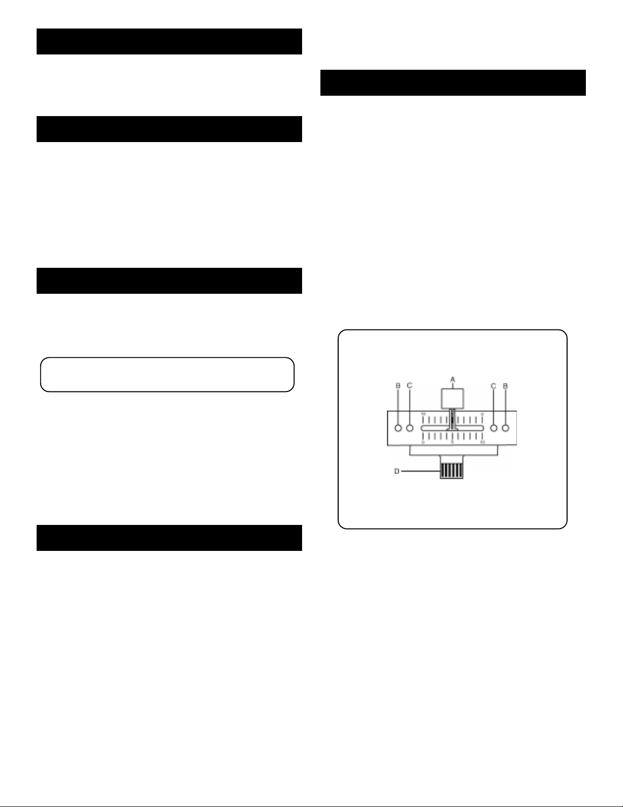
4. CROSSFADER SECTION: The CROSSFADER (24) allows the mixing
of one source into another. The left side of the CROSSFADER (24) is
channel 1 and the right side is channel 2. The CROSSFADER (24) in
your unit is removable and if the need arises can be easily replaced.
Crossfader units are available in three varieties. Part # RF-45 (which
is identical to the crossfader supplied with the mixer) has a 45 mm
travel from side to side. Part # RF-30 is available with a 30 mm travel
distance. Also available is the PSF-45 with a special curve designed
for scratch mixing. Just purchase one of these crossfader units
from your Gemini dealer and follow these instructions:
1. Unscrew the outside FADER PLA TE SCREWS (B). Do not
touch the INSIDE SCREWS (C).
2. Carefully lift the fader and unplug the CABLE (D).
3. Plug the new fader into the cable and place it back in the
mixer.
4. Screw the fader to the mixer.
Connections
1. Make sure that the POWER (22) switch is in the off position. The
POWER LED (17) will be off. This unit comes supplied with a 15 volt
AC adaptor. Plug the male pin of the adaptor into the rear panel
POWER JACK (1). Then plug the adaptor into a proper power
source.
2. The XDJ-19 is supplied with 2 sets of amp output jacks. Use the
MASTER 1 (3) or the MASTER 2 (2) jacks to connect to your mixer
to your main amplifier. You can use the second set of jacks to
connect the mixer to the record input of your recorder enabling you
to record your mix or as a second zone with an additional amplifier.
3. The MIC (9) input (found on the rear panel) accepts a 1/4"
connector. Both balanced and unbalanced microphones can be
used.
4. On the rear panel are 2 stereo PHONO (5, 8) inputs and 2 stereo
LINE (4, 7) inputs. The phono inputs will accept only turntables with
a magnetic cartridge. A GROUND (6) screw for you to ground your
turntables is located on the rear panel. The stereo line inputs will
accept any line level input such as a CD player, a cassette player,
etc.
5. PUNCH IN: The PUNCH IN (23) buttons allow you to add a channel’s
signal to the mix when the crossfader is set to the opposite channel.
6. OUTPUT CONTROL: The level of the MASTER OUTPUT (2, 3) is
controlled by the MASTER (21) slide.
7. TALKOVER SECTION: The purpose of the talkover section is to allow
the program playing to be muted so that the mic can be heard above
the music. The MIC/TALKOVER (10) switch has three settings.
When the MIC/TALKOVER (10) switch is in the bottom position, the
MIC and talkover are both off. When the MIC/TALKOVER (10)
switch is in the center position the MIC is on, the MIC INDICATOR
(11) will glow, but talkover is off. When the MIC/TALKOVER (10)
switch is in the top position, the MIC and talkover will be on and the
volume of all sources except the Mic input are lowered by 16 dB.
The MIC (12) level controls the level of the MIC.
8. CUE SECTION: By connecting a set of headphones to the
HEADPHONE (27) jack, you can monitor either channel or both
together. Select the Channel 1 by sliding the CUE SLIDER (26)
control to the left or Channel 2 by sliding the CUE SLIDER (26)
control to the right. Use the CUE LEVEL (25) control to adjust the
Page 3
Page 4

headphone volume without effecting the overall mix.
9. DISPLAY: The DISPLAY (16) indicates the MASTER output left and
right levels.
Specifications
INPUTS:
Mic......................................................................1.5 mV 2 kOhm balanced
Phono....................................................................................3mV 47 kOhm
Line...................................................................................150 mV 15 kOhm
OUTPUTS:
Amp/Booth.......................................................................0 dB 1V 400 Ohm
Max..............................20 V Peak to Peak
GENERAL:
Gain............................................................................................0 to -20 dB
Frequency Response...........................................20 Hz - 20 kHz ± 2 dB
Distortion..........................................................................................0.02%
S/N Ratio........................................................................better than 80 dB
Talkover Attenuation........................................................................-16 dB
Headphone Impedance..................................................................16 Ohm
Power Source.............................................................115V/15V AC 0.5 A
230V/15V AC 0.5 A
Dimensions.....................................19” x 3.5” x 8” (483 x 90 x 203 mm)
Weight................................................................................7.5 lbs (3.4 kg)
Page 4
Page 5

Introducción
Funcionamiento
Felicitaciones por su compra del mezclador Brand X por Gemini XDJ-19.
Este mezclador de la más avanzada tecnología está respaldado por una
garantía de tres años, salvo el crossfader y los mandos corredizos de
canal. Antes de usarlo, le recomendamos leer cuidadosamente todas las
instrucciones.
Características
• 2 canales estereo fonicos
• 2 entradas fono, 1 entradas de línea y 1 entrada para micrófono
• Mandos de ganancia
• Funciones Punch In
• función Talkover y control de nivel para micrófono
• 2 juegos de Salidas maestras
• Sección Cue (referencia) con control de nivel
Precauciones
1. Deberán leerse todas las instrucciones de operación antes de usar el
equipo.
2. Para reducir el riesgo de shock eléctrico, no abra esta unidad. No
contiene PIEZAS REEMPLAZABLES POR EL USUARIO. Por favor,
refiera el servicio a un técnico de servicio calificado.
3. No exponga la unidad a la luz solar directa ni a una fuente de calor,
por ejemplo, un radiador o estufa.
4. Esta unidad sólo deberá limpiarse con un paño húmedo. Evite el uso
de disolventes u otros detergentes de limpieza.
5. Para mover este equipo, colóquelo en la caja y empaque original, a
fin de reducir el riesgo de daños durante el transporte.
6. NO DEJE ESTA UNIDAD EXPUESTA A LLUVIA O HUMEDAD.
7. NO USE LIMPIADORES DE ROCÍO O LUBRICANTES EN
CUALESQUIER CONTROLES O INTERRUPTORES.
1. ENCENDIDO: Una vez que haya efectuado todas las conexiones de
los equipos a su mezclador, oprima el INTERRUPTOR DE ENERGÍA
- POWER (22). Se encenderá la unidad así como el DEL ROJO de
ENERGÍA - POWER LED (17).
2. CANAL 1: El mando GANANCIA - GAIN (13) le permite ajustar
individualmente la ganancia del canal. El interruptor # (14) le permite
seleccionar la entrada PHONO 1 (8) o LINE 1 (7). El CHANNEL
SLIDE (15) (cursor deslizante de canal) controla el volumen de
entrada de este canal.
3. CANAL 2: El mando GANANCIA - GAIN (20) le permite ajustar
individualmente la ganancia del canal. El interruptor # (18) le permite
seleccionar la entrada PHONO 2 (5) o LINE 2 (4). El CHANNEL
SLIDE (19) (cursor deslizante de canal) controla el volumen de
entrada de este canal.
4. SECCIÓN DE ATENUADOR DE TRANSFERENCIA: El
ATENUADOR DE TRANSFERENCIA - CROSSFADER (24) le
permite mezclar una fuente en otra. El lado izquierdo del
ATENUADOR DE TRANSFERENCIA corresponde al canal 1 y el
lado derecho corresponde al canal 2. El ATENUADOR DE
TRANSFERENCIA de su aparato es removible y, en caso de
necesidad, su reemplazo es fácil. Se ofrecen unidades de atenuador
de transferencia de tres tamaños. La Pieza Nº RF-45 (idéntico al
atenuador de transferencia suministrado con su unidad) tiene un
recorrido de 45mm de un lado a otro. También se ofrece la pieza nº
RF-30, que tiene un recorrido de 30mm. También se ofrece la pieza
PSF-45 con curva especial diseñada para mezclar el efecto de
frotamiento. Simplemente compre cualquiera de estas unidades de
atenuador de transferencia de su distribuidor Gemini y siga las
instrucciones siguientes:
1. Destornille los TORNILLOS EXTERIORES de la PLACA
DEL ATENUADOR (B). No toque LOS TORNILLOS
INTERNOS (C).
2. Levante cuidadosamente el atenuador y desenchufe el
CABLE (D).
3. Conecte el nuevo atenuador al cable y póngalo de nuevo
dentro del mezclador.
4. Atornille el atenuador en el mezclador.
Conexiones
1. Cerciórese de que el interruptor de ENERGÍA - POWER (22) esté en
la posición off (apagada). El DEL de ENERGÍA - POWER LED (17)
estará apagado. Esta unidad se suministra con un adaptador CA de
15 voltios. Enchufe la clavija macho del adaptador en el JACK DE
ENERGÍA - POWER JACK (1) del panel trasero. Luego enchufe el
adaptador en una fuente de energía apropiada.
2. El aparato XDJ-19 está dotado de 2 series de jacks de salida para
amplificador. Use los jacks MAESTRO 1- MASTER 1 (3) o
MAESTRO 2 - MASTER 2 (2) para conectar el mezclador a su
amplificador principal. Se puede utilizar la segunda serie de jacks
para conectar el mezclador a la entrada de su registrador lo que le
permite registrar su mezcla o como seguna zona con amplificador
adicional.
3. La entrada MIC (9) (que se encuentra en el panel trasero) acepta
conector de 1/4 de pulgada. Se puede utilizar micrófonos
balanceados y no balanceados.
4. En el panel trasero hay 2 entradas estereofónicas PHONO (5, 8) y 2
entradas estereofónicas LINE (4, 7). Las entradas fonográficas
solamente aceptarán giradiscos con cartucha magnética. Un
GROUND (6) (tornillo de puesta a la tierra) para poner el giradiscos a
tierra se encuentra en el panel trasero. Las entradas de línea
estereofónicas aceptarán cualquier entrada de nivel de línea tal como
tocadisco de discos compactos o casetera, etc.
5. Los audífonos se enchufan en el jack de HEADPHONE (27)
(audífonos) montado en el panel delantero.
5. PUNCH IN: El botón PUNCH IN (23) le permite añadir la señal de un
canal a la mezcla cuando el atenuador de transferencia está
arreglado para el canal opuesto.
6. CONTROL DE LA SALIDA: El volumen de MASTER OUTPUT (2, 3)
(salida del amplificador) se controla por el cursor corredizo MASTER
(21) (principal).
7. SECCIÓN TALKOVER: El propósito de la sección talkover es de
permitir al programa de ponerse sordina para que se pueda oír el
mensaje del micrófono por encima de la música. El interruptor MIC/
TALKOVER (10) tiene tres arreglos. Cuando el interruptor MIC/
TALKOVER (10) ocupa la posición inferior, el MIC y la función
talkover están ambos apagados. Cuando el interruptor MIC/
TALKOVER (10) ocupa la posición central, el MIC está activado, el
INDICADOR MIC - MIC INDICATOR (11) se prenderá pero la función
talkover está apagada. Cuando el interruptor MIC/TALKOVER (10)
ocupa la posición superior, el MIC y la función talkover estarán
prendidos y el volumen de todas las fuentes salvo la entrada Mic
serán reducidas por 16 dB. El MIC (12) controla el volumen del
micrófono.
Page 5
Page 6

8. SECCION DE REFERENCIA: Al conectar un set de audífonos al jack
de HEADPHONES (27), se puede monitorear cualquiera de los
canales o ambos juntos. Seleccione el canal 1 al deslizar el mando
CUE SLIDER (26) a la izquierda o el canal 2 al deslizar el mando
CUE SLIDER (26) a la derecha. Haga uso del mando CUE LEVEL
(25) para ajustar el volumen del casco sin afectar la mezcla global.
9. PRESENTACIÓN: La PRESENTACIÓN - DISPLAY (16) indica los
niveles de salida derecha e izquierda del control MAESTRO -
MASTER.
Especificaciones técnicas
ENTRADAS:
Micrófono................................................1,5 mV 2 kOhmios balanceados
Fonógrafo......................................................................3 mV 47 kOhmios
Línea............................................................................150 mV 15 kOhmios
SALIDAS:
Amplificador/cabina...................................................0 dB 1 V 400 Ohmios
Máx........................20 V pico-pico
GENERALES:
Ganancia.............................................................................de 0 a -20 dB
Respuesta de frecuencia....................................20 Hz - 20 kHz ± 2 dB
Distorsión...........................................................................................0,02%
Relación señal/ruido.......................................................superior a 80 dB
Atenuación talkover..........................................................................-16 dB
Impedancia del audífono............................................................16 Ohmios
Fuente de energía........................................................115V/15V AC 0.5 A
230V/15V AC 0.5 A
Dimensiones...............................................................483 x 90 x 203 mm
Peso..................................................................................................3.4 kg
Page 6
Page 7

In the USA: If you experience problems with this unit,
call 1-732-738-9003 for Gemini Customer Service.
Do not attempt to return this equipment to your dealer.
Parts of the design of this product may be protected by worldwide patents.
Information in this manual is subject to change without notice and does not
represent a commitment on the part of the vendor. Gemini Sound Products Corp.
shall not be liable for any loss or damage whatsoever arising from the use of
information or any error contained in this manual.
No part of this manual may be reproduced, stored in a retrieval system or
transmitted, in any form or by any means, electronic, electrical, mechanical, optical,
chemical, including photocopying and recording, for any purpose without the
express written permission of Gemini Sound Products Corp.
It is recommended that all maintenance and service on this product is performed
by Gemini Sound Products Corp. or its authorized agents.
Gemini Sound Products Corp. will not accept liability for loss or damage caused
by maintenance or repair performed by unauthorized personnel.
Worldwide Headquarters • 120 Clover Place, Edison, NJ 08818 • USA
T el: (732) 738-9003 • Fax: (732) 738-9006
France • G.S.L. France • 11, A venue Leon Harmel, Z.I. Antony, 92160 Antony, France
Tel: + 33 (0) 1 55 59 04 70 • Fax: + 33 (0) 1 55 59 04 80
Germany • Gemini Sound Products GmbH • Ottostrasse 6, 85757 Karlsfeld, Germany
Tel: 08131 - 39171-0 • Fax: 08131 - 39171-9
UK • Gemini Sound Products • Unit C4 Hazleton Industrial Estate, Waterlooville, UK P08 9JU
Tel: 087 087 00880 • Fax: 087 087 00990
Spain • Gemini Sound Products S.A. • Mino, 112, Nave 1, 08223 Terrassa, Barcelona, Spain
Tel: 011-34-93-736-34-00 • Fax: 011-34-93-736-34-01
© Gemini Sound Products Corp. 2001 All Rights Reserved
Page 7
 Loading...