

Page 1
GE MDS TD220 Manual
Version 12
TD220_manual12.doc Page 1 of 38 1/10/2011
Page 2

Table of Contents
1 Important Information ............................................................................................................ 3
1.1 Antenna Installation Warnings ........................................................................................ 3
1.2 ESD Notice ..................................................................................................................... 3
1.3 FCC Approval Notice ...................................................................................................... 3
1.4 FCC Part 15 Notice ........................................................................................................ 3
1.5 FCC Part 80 Notice ........................................................................................................ 3
1.6 Industry Canada ICES-003 and RSS-119 ...................................................................... 4
2 Introduction ........................................................................................................................... 5
3 Interfaces .............................................................................................................................. 7
3.1 Data Interface (DB-25) ................................................................................................... 7
3.2 USB ................................................................................................................................ 8
3.3 Power .............................................................................................................................. 8
3.4 Antenna Connector ......................................................................................................... 8
4 Common Setup Tasks ........................................................................................................... 9
4.1 Key the Transmitter for Test Purposes ........................................................................... 9
4.2 Prepare the Network Interface for a Radio ..................................................................... 9
4.3 Set Up a Base Unit ......................................................................................................... 9
4.4 Set Up a Mobile Unit ....................................................................................................... 10
4.5 Perform Test Polling ....................................................................................................... 10
5 Menu Interface ...................................................................................................................... 16
5.1 Main Menu ...................................................................................................................... 17
5.2 Network Configuration Menus ........................................................................................ 18
5.3 Base System Configuration Menus ................................................................................ 21
5.4 Mobile System Configuration Menu ............................................................................... 23
5.5 Radio Configuration Menu .............................................................................................. 24
5.6 GPS Configuration Menu ................................................................................................ 25
5.7 Security Configuration Menu .......................................................................................... 25
5.8 Statistics/Logging Menus ................................................................................................ 26
5.9 Device Information Menus .............................................................................................. 30
5.10 Maintenance/Tools Menus ............................................................................................. 31
6 Troubleshooting .................................................................................................................... 34
7 ITCSLOG Utility ..................................................................................................................... 35
8 Change Log ........................................................................................................................... 38
TD220_manual12.doc Page 2 of 38 1/10/2011
Page 3

1 Important Information
0-
6 dBi
6-
10 dBi
10-
16.5 dBi
Minimum RF Safety
Distance
1.50 meters
2.37 meters
5.01 meters
Radio Power Setting
ERP Maximum Antenna Gain
2 W 4 W 3 dBd (5.2 dBi)
4 W 4 W 0 dBd (2.2 dBi)
2 W 20 W
10dBd (12.2 dBi)
1.1 Antenna Installation Warnings
1. All antenna installation and servicing is to be performed by qualified technical personnel
only. When servicing the antenna, or working at distances closer than those listed below,
ensure the transmitter has been disabled.
2. Depending upon the application and the gain of the antenna, the total composite power
could exceed 90 watts EIRP. For fixed/mobile configuration, the distances in the table below
must be followed.
Antenna Gain vs. Minimum Safety Distance
(Based upon a 50% Duty Cycle, 0 dB Feedline Loss) Controlled Exposure limits
Fixed/Mobile Antenna Gain
1.2 ESD Notice
To prevent malfunction or damage to this product, which may be caused by Electrostatic Discharge
(ESD), the radio should be properly grounded at the time of installation. In addition, the installer or
maintainer should follow proper ESD precautions, such as touching a bare metal object to dissipate
body charge, prior to touching components or connecting/disconnecting cables.
1.3 FCC Approval Notice
This device is offered as a licensed transmitter per FCC Parts 80, 90, and 95. It is approved for use
under the following conditions: Changes or modifications not expressly approved by the party
responsible for compliance will void the user’s authority to operate the equipment.
1.4 FCC Part 15 Notice
This equipment has been tested and found to comply with the limits for a Class A digital device,
pursuant to Part 15 of the FCC Rules.
Operation is subject to the following two conditions: (1) this device may not cause interference, and
(2) this device must accept any interference, including interference that may cause undesired
operation of the device. Changes or modifications not expressly approved by the party responsible
for compliance could void the user's authority to operate the equipment.
1.5 FCC Part 80 Notice
For FCC Part 80, the Effective Radiated Power (ERP) must be less than or equal to 4 Watts for mobile
use and 20 Watts for fixed use. This can be accomplished by adjusting the output power of the
radio and selecting an antenna with appropriate gain. Consult the following table for assistance in
setting the output power and selecting an antenna to maintain compliance. The table provides
examples, however other combinations can be used.
TD220_manual12.doc Page 3 of 38 1/10/2011
Page 4

10 W
20 W
3 dBd (5.2 dBi)
20 W
20 W
0 dBd (2.2 dBi)
1.6 Industry Canada ICES-003 and RSS-119
This Class A digital apparatus complies with Canadian ICES-003 and with RSS-119. Cet appareil
numérique de la classe A est conforme à la norme NMB-003 du Canada.
TD220_manual12.doc Page 4 of 38 1/10/2011
Page 5
2 Introduction
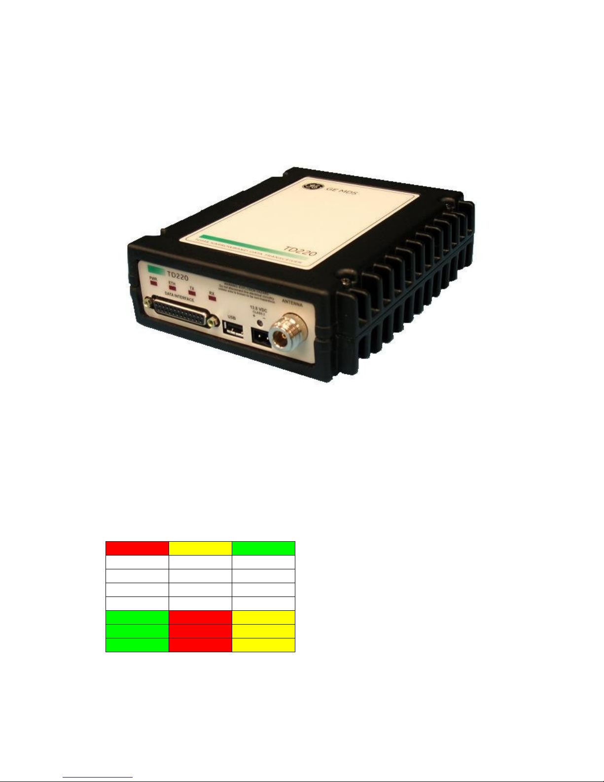
The GE MDS TD 220 is a 25-Watt 220 MHz GMSK data radio intended for bridging ITCS messages
over the air between locomotives and wayside devices. The data interface is Ethernet, with UDPencapsulated ITCS message payload.
Each second is divided into 8 133-byte time slots. The first of the 8 timeslots each second is always
reserved for bases A, B, or C to transmit beacon information to the mobiles in the area. Following
the beacon are 4 (or 5) time slots that are always reserved for mobiles to transmit. At the end of
each second, are 3 (or 2) time slots that can be used by bases or mobiles. These slots are used with
the following priority: the previous base, the current base, and then mobiles. In other words, during
second 1 in the table below, base A actually has priority over the last three slots. If A does not use
them, B can use them. If B does not use them, mobiles can. Bases reserve these time slots with
flags in the beacon. This scheme maximizes the potential for utilizing all slots.
Second 0 Second 1 Second 2
0 A B C <- Beacon slots always used by a specific base
1 M M M <- Slots available for CW-based mobile transmissions
2 M M M <- Slots available for CW-based mobile transmissions
3 M M M <- Slots available for CW-based mobile transmissions
4 M M M <- Slots available for CW-based mobile transmissions
5 C or A or M A or B or M B or C or M <- Slots that can be used by one of two bases
6 C or A or M A or B or M B or C or M <- Slots that can be used by one of two bases
7 C or A or M A or B or M B or C or M <- Slots that can be used by one of two bases
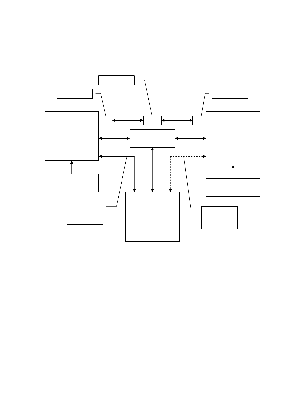
While this radio has been designed to pass ITCS messages, it can pass generic UDP traffic
following the conventions outlined in the following figures.
TD220_manual12.doc Page 5 of 38 1/10/2011
Page 6
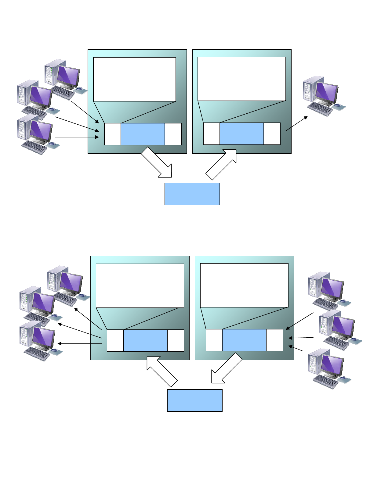
UDP Header stripped by
UDP Header added by
BASE MOBILE
UDP Header added by
UDP Header stripped by
Base Radio
IP Address of Base Radio,
Port Number on which the
Base is configured to listen
Mobile Radio
IP Address and Port Number
to which the Mobile is
configured to send
Payload
Payload
Over the Air
Payload
Figure 1. Base to Mobile Communications – Many to One
BASE MOBILE
Base Radio
IP Address and Port Number
as triggered by address
embedded in payload
Mobile Radio
IP Address of Mobile Radio,
Port Number on which the
Mobile is configured to listen
Payload
Payload
Over the Air
Payload
Figure 2. Mobile to base Communications – Many to Many
TD220_manual12.doc Page 6 of 38 1/10/2011
Page 7

3 Interfaces
Notes
Reserved
GPS NMEA Data Expected
Reserved
Reserved
Reserved
Reserved
Reserved
Reserved
Reserved
Reserved
For TTL PPS, leave this open
For TTL PPS, use this input
Console
Console
3.1 Data Interface (DB-25)
The Data Interface has several ports integrated into one connector: Ethernet, COM1 and COM2
Serial Ports, and GPS signaling. Note that COM3 is connected internally and therefore not available
on pins labeled with “COM3.”
DB-25
Pin
1 COM3_DCD Input
2 COM2_TXD Input
3 COM2_RXD Output
4 COM2_RTS Input
5 COM2_CTS Output
6 COM3_TXD Output
7 GND Input/Output
8 COM2_DCD Output
9 COM3_CTS Input
10 COM3_RTS Output
11 COM3_DTR Output
12 COM3_RXD Input
13 GND Input/Output
14 ETH_TX_H Output
15 ETH_TX_L Output
16 ETH_RX_H Input
17 ETH_RX_L Input
18 EXT_KEY Output
19 EXT_DET Input
20 COM2_DTR Input
21 ALARM_OUT Output
22 GPS_PPS_L Input
23 GPS_PPS_H Input
24 COM1_RXD Input
25 COM1_TXD Output
The DB-25 connector is female, and the orientation of the connector as looking into the front panel
of the unit is as shown below.
13
Signal
12 11 10 9 8 7 6 5 4 3 2 1
Direction WRT MDS
Equipment
24 23 22 21 20 19 18 17 16 15 14
25
TD220_manual12.doc Page 7 of 38 1/10/2011
Page 8
3.2 USB
Pin Signal Name
Description
1 PC_USB_+5V
+5 VDC
2 USBD
- USB Data Minus
3 USBD+
USB Data Plus
4 GROUND
Ground
Pin Signal Name
Direction with respect to MDS Equipment
Description
1 (L) PWR
Input
13.8 VDC input, 7
2 (R) GROUND
Input
Power return.
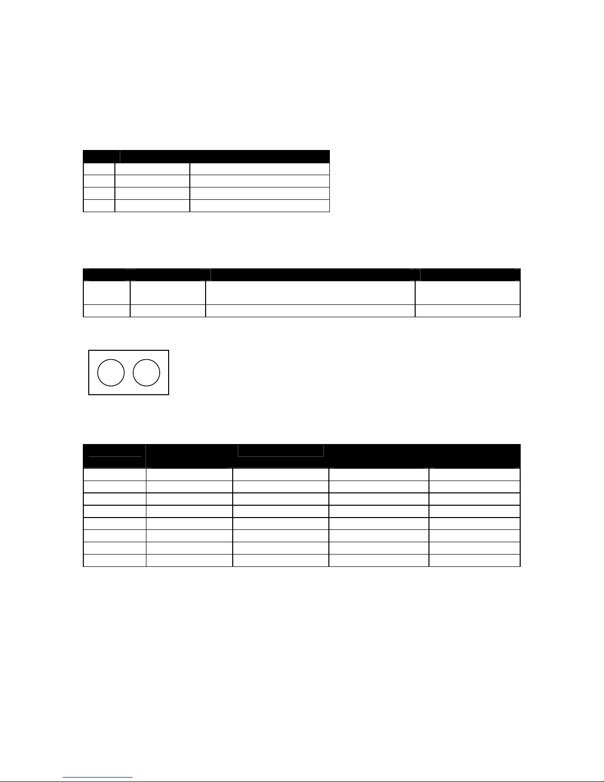
Voltage (V)
RF Power Out
Duty Cycle (%)
Current Required
Thermal
12 0 (RX)
100 0.3 TBSL
12 2 100 TBSL
TBSL
12 10 50 TBSL
TBSL
12 25 30 TBSL
TBSL
13.8 0 (RX)
100 0.3 TBSL
13.8 2 100 1.2 14
13.8 10 50 3.2 15
13.8 25 30 5.5 15
The radio provides a USB Port conforming to version 1.1 of the USB standard. This port is provided
for future features such as ITCS logging to text files on a memory stick. Consult GE MDS for
information on this feature. The pinout for this connector is given in the table below.
3.3 Power
The power connector is a screw-secured 2-pin connector.
Amps maximum.
The pin orientation as looking into the connector is shown below.
L R
Consult the following table to determine how much current is required for receiving or transmitting
vs. input voltage and RF power output.
(W)
(A)
Dissipation (W)
3.4 Antenna Connector
The Antenna Connector is a type N female connector with 50-Ohm characteristic impedance.
TD220_manual12.doc Page 8 of 38 1/10/2011
Page 9

4 Common Setup Tasks
4.1 Key the Transmitter for Test Purposes
1. Log in to the radio on its COM1 console using a serial terminal emulator program.
2. Go to the Radio Configuration menu.
3. Select the frequency for the test transmission.
4. Select the RF Output Power to use. Note that power levels greater than 2 Watts will
timeout after a 5-second period by default. Ensure ventilation with supplemental forced
airflow if longer durations are desired.
5. Select the Force TX Key menu option.
6. When finished, deselect the Force TX Key menu option.
4.2 Prepare the Network Interface for a Radio
Each radio is assigned an IP Address, a Netmask, and a Gateway IP Address. The IP Address and
Netmask should be chosen carefully. The radio will network directly with other equipment with IP
Addresses that are on a common Subnet. IP Addresses that begin with the same numerical IP
address bits where the Netmask is one will be on the same Subnet. For example, if the IP Address is
10.4.100.1 and the Netmask is 255.255.0.0, the radio will attempt direct Ethernet communication
with any node whose IP Address begins with 10.4. If a message is bound for a node outside of the
10.4 network, it will be sent to the Gateway IP address instead so that it can be placed from the
radio’s subnet onto another subnet.
1. Log in to the radio on its COM1 console using a serial terminal emulator program.
2. Go to the IP Configuration menu.
3. Set the IP address of the radio, plus the Netmask and Gateway.
4. Go to the Maintenance/Tools Menu and select the Ping Utility.
5. Enter the IP address of a known node on the network.
6. Execute the Ping and observe the results. If the network interface is working properly, Ping
responses should be received.
4.3 Set Up a Base Unit
1. If not already done, complete steps from 4.2 above.
2. Connect the RS-232 NMEA serial data output from the GPS receiver to the Base Radio via
the radio’s COM2 port. Drive serial data into the radio on DB-25 pin 2.
3. Connect the GPS’s PPS output to the Base Radio. Drive TTL into the radio on DB-25 pin 23.
4. Log in to the radio.
5. Go to the System Configuration menu.
6. Set the unit to Base mode and reboot if necessary.
7. Set the base type (A, B, or C).
8. Set the window size. Mobiles will transmit in a randomly selected available slot among
2^(Window Size) slots. For small networks, this can be 1. For larger networks, use a
Window Size that provides double or quadruple the number of mobiles expected under one
base at a time.
9. Set the IP Port on which the base will receive UDP messages from wayside devices.
10. Set up an ITCS Translation Table. For test purposes, this may be as simple as setting up one
known address with a mask of all “F’s”.
11. Verify Ethernet Link using the Ping utility in the Maintenance/Tools Menu.
12. Begin sending UDP data.
13. Verify the TX LED illuminates and the radio begins transmitting over the air.
TD220_manual12.doc Page 9 of 38 1/10/2011
Page 10

4.4 Set Up a Mobile Unit
1. If not already done, complete steps from 4.2 above.
2. Log in to the radio.
3. Go to the System Configuration menu.
4. Set the unit to Mobile mode and reboot if necessary.
5. Set the IP Port to which the mobile will send messages received over the air.
6. Set the IP Port on which the mobile will accept incoming messages for transmission over
the air.
7. Verify Ethernet Link using the Ping utility in the Maintenance/Tools Menu.
8. Ensure at least one base is present in the neighborhood of this radio so that it can detect
beacons and synchronize timing.
9. Begin sending UDP data from a polling program.
10. Verify the TX LED illuminates and the radio begins transmitting over the air.
4.5 Perform Test Polling
1. Set up the Base and Mobile as above.
2. Connect as shown in the following diagram. Note: this is for bench testing only, i.e. not for
sensitivity testing. Sensitivity testing requires complete RF isolation or mixed operation to
prevent the leakage path from being the dominant RF path between units. For bench
testing, use attenuation so that the signal level at every unit that is participating is around
–70 to –50 dBm.
TD220_manual12.doc Page 10 of 38 1/10/2011
Page 11
40 dB/ 10 W
Test Polling Setup
30 dB/ 50 W
TD220 Base
Set for 2 Watts
13.8 VDC < 5 Amps
Radio
COM1 to PC
Serial Port
30 dB/ 50 W
TD220 Mobile
Set for 2 Watts
Ethernet Hub
13.8 VDC < 5 Amps
Test PC
Radio
COM1 to PC
Serial Port
TD220_manual12.doc Page 11 of 38 1/10/2011
Page 12

3. Configure the Base as follows:
System Configuration Menu
-==========================================================================-
A) Unit Type Base
B) Base Unit Zone A
C) Window Size 2
D) ITCS UDP Receive Port 50000
E) Timing Signal Timeout 60 Seconds
F) ITCS Translation Table
Select a letter to configure an item, <ESC> for the prev menu
ITCS Translation Table Menu
-========================================================================== Dest Addr Addr Mask Dest IP Addr Dest Port RSSI Opt
------------------------------------------------------------------------- A) 12345678 FFFFFFFF 10.4.147.170 53000 NO
B) New Entry
Select a letter to configure an item, <ESC> for the prev menu
Radio Configuration Menu
-==========================================================================-
A) Base Transmit Frequency 221.900000 MHz
B) Mobile Transmit Frequency 221.900000 MHz
C) Transmit Slots 4
D) Output Power 2 W
E) Force Tx Key Normal
F) TX Key Timeout 5 sec
Select a letter to configure an item, <ESC> for the prev menu
4. Reboot the Base
5. Obtain the Parametric Poller (parm_poller.exe) from GE MDS. This utility saves its settings
to parm_poller.ini in the current directory, so make one directory for the base and a
different directory for the mobile.
TD220_manual12.doc Page 12 of 38 1/10/2011
Page 13

6. In the base directory, create the parm_poller data configuration file (parm_poller.parms) as
shown below.
set ::parms {
{ 0 "Dest" 32 "78563412" "RW" }
{ 1 "Src" 32 "F0DEBC9A" "RW" }
{ 2 "Flags" 8 "00" "RW" }
{ 3 "Length" l1 "00" "RO" }
{ 4 "Seq No" sn "00" "RW" }
{ 5 "Data" nt "Hello, World" "RW" }
}
7. Set up the base parm_poller as shown below, where 10.4.144.100 is replaced with the IP
address of your base.
TD220_manual12.doc Page 13 of 38 1/10/2011
Page 14

8. Configure the Mobile as follows:
Lab Test Mobile
System Configuration Menu
-==========================================================================-
A) Unit Type Mobile
B) Locomotive Server 10.4.147.170
C) Locomotive Server Port 51000
D) OBC Info Packet disabled
E) ITCS UDP Receive Port 52000
F) Timing Signal Timeout 60 Seconds
Select a letter to configure an item, <ESC> for the prev menu
Radio Configuration Menu
-==========================================================================-
A) Base Transmit Frequency 221.900000 MHz
B) Mobile Transmit Frequency 221.900000 MHz
C) Transmit Slots 3
D) Output Power 2 W
E) Force Tx Key Normal
F) TX Key Timeout 5 sec
Select a letter to configure an item, <ESC> for the prev menu
TD220_manual12.doc Page 14 of 38 1/10/2011
Page 15

9. Reboot the Mobile.
10. Copy the base’s parm_poller.parms file to the mobile directory.
11. Set up the mobile parm_poller as shown below.
12. Click Start Polling on both units and observe the message counts and sequence number
increment.
13. If additional visibility is desired, obtain itcslog.exe from GE MDS. This utility captures
messages from the logging output of the TD220 radios and displays statistics about them.
The IP Port Number is the port number configured on the radio for ITCS logging.
TD220_manual12.doc Page 15 of 38 1/10/2011
Page 16

5 Menu Interface
Parameter
R/W Description
Device Name
R*
User-configured name for this radio. Set this from the Device Names
IP Addre
ss R* IP Address for this radio. Set this from the IP Networking menu.
Device Status
R
“Initializing” during startup and/or internal RF deck reprogramming,
Location
R*
User-configu
red location for this radio. Set this from the Device
Serial Number
R
The manufacturer’s serial number for this radio. Set only in the
Login with user name admin, password admin.
When logged in, the Starting Information Screen is displayed.
menu.
“Operational” when functioning, “Alarmed” when error condition(s)
exist.
Names menu.
TD220_manual12.doc Page 16 of 38 1/10/2011
Page 17

Parameter
R/W Description
factory.
Uptime
R
Elapsed time since the radio was started.
Current Firmware
R*
The version number of th
e currently operating firmware. Reprogram
firmware from the Reprogramming Menu.
Current User
R
Login level.
Parameter
R/W Description
A) Starting Information
Returns to the ope
ning menu.
B) Network
Set the radio’s IP Address, Netmask, and Gateway.
C) System
Set the radio’s Mode (Base/Mobile) and other application
-
specific
D) Radio
Configuration
Set the radio’s Frequencies, Base transmit slot allocation (3/4), RF
E) GPS Configuration
Set up the GPS NMEA and PPS
connections
F
) Security
Set up how the radio may be
accessed.
G
) Statistics / Logging
Obtain historical and current statistics about the radio’s payload
H
) Device Information
Set up the radio’s Date, Time, Console Baud Rate and Names.
I
) Maintenance / Tools
Access the radio’s Firmware Reprogramming, Configuration
R* - This parameter is writable from another menu.
5.1 Main Menu
Screen
Configuration
Configuration
Configuration
operating parameters including the Base’s ITCS translation table.
Power Output, and access the Force TX Key function.
performance, and access ITCS Logging configuration.
Review the radio’s Model, Serial Number, and Uptime.
Script, and Ping Utility menus.
TD220_manual12.doc Page 17 of 38 1/10/2011
Page 18

5.2 Network Configuration Menus
Parameter
R/W Description
A) IP Configuration
Access the IP Co
nfiguration menu to set the IP Address, Netmask,
B) SNMP Agent
Access the SNMP Agent Configuration Menu.
Ethernet Address
R
Displays the hardware MAC address for the Ethernet port.
Configuration
and Gateway IP Address.
TD220_manual12.doc Page 18 of 38 1/10/2011
Page 19

Parameter
R/W Description
A
) IP Address
R/W The IP address that this radio will use for its Ethernet interface.
B) IP Netmask
R/W The subnet mask for the network this radio is part of.
C) IP Gateway
R/W The IP address of the gateway that will pass traffic from the
Parameter
R/W Description
A) SNMP Read
R/W SNMP community string used for SNMPv1/SNMPv2c read access.
B) SNMP Write
R/W SNMP community string used for SNMPv1/SNMPv2c write access.
C) SNMP Trap
R/W SNMP community string used for SNMPv1
/SNMPv2c trap access.
radio’s subnet to nodes on other networks.
Note: The IP Address and IP Gateway must be on the same subnet or a Network Interface error will
occur.
Community
Community
This string can be up to 30 alphanumeric characters.
This string can be up to 30 alphanumeric characters.
TD220_manual12.doc Page 19 of 38 1/10/2011
Page 20

Community
This string can be up to 30
alphanumeric
characters.
D) SNMP
v3 Auth
Password
R/W Authentication password stored in flash. Will be used when Agent
E)
SNMP v3 Priv
R/W Privacy password stored in flash. Will be used when Agent is
F) SNMP Mode
R/W This specifies the mode of operation of the SNMP Agent. Choices
G) Trap Version
R/W This specifies what version of SNMP will be used to encode the
H) Auth Trap Enable
R/W Indicates whether
or not
traps will be generated f
or login events.
I) SNMP v3 Password
R/W Determines whether v3 passwords are managed locally or via an
J) SNMP Trap Manager
R/W Specifie
s an
SNMP Manager on the network that traps will be sent
K) SNMP Trap Manager
R/W Specifies an SNMP Manager on the network that traps will be sent
L) SNMP Trap Manager
R/W Specifies an SNMP Manager on the network that traps will be sent
M) SNMP Trap
R/W Specifies an SNMP Manager on the network that traps will be sent
is managing passwords locally or initially for all cases on reboot.
This is the SNMPv3 password used for Authentication (currently
only MD5 is supported). This string can be up to 30 alphanumeric
characters.
Password
Mode
#1
#2
#3
managing passwords locally or initially for all cases on reboot.
This is the SNMPv3 password used for Privacy (DES encryption).
This string can be between 8 and 30 alphanumeric characters.
are disabled, v1_only, v2_only, v3_only, v1-v2, and v1-v2-v3. If the
mode is disabled, then the Agent will not respond to any SNMP
traffic. If the mode is v1_only, v2_only, or v3_only, then the Agent
will only respond to that version of SNMP traffic. If the mode is v1v2, or v1-v2-v3, then the Agent will respond to the specified
version of SNMP traffic. The default mode is v1-v2-v3 (trilingual).
outgoing traps. The different versions of SNMP will include
different information in the traps. The choices are v1_traps,
v2_trap, and v3_traps. When v3_traps are selected, v2-style traps
will be sent but with a v3 header.
SNMP Manager. The different behaviors of the Agent depending
on the mode specified here are described above.
to.
to.
to.
Manager #4
to.
TD220_manual12.doc Page 20 of 38 1/10/2011
Page 21

5.3 Base System Configuration Menus
Parameter
R/W Description
A) Unit Type
R/W Bases send beacons out once per epoch and coordinate
B) Base Unit Zone
R/W Bases are one of three types, A, B, and C. Each base coordinates
C) Window Size
R/W When a mobile is ready to transmit, it chooses at random from
D) ITCS UDP Receive
R/W Wayside devices send UDP messages to this IP port on the radio’s
E) Timing Signal
R/W If the GPS Pulse Per Second input is missing for this duration, the
F) ITCS Trans
lation
Access the ITCS
Address
Translation Table to add or delete routing
Port
Timeout
Table
downstream messages. Mobiles listen to bases to identify free
slots, and then select random slots in which to place their
upstream messages.
slots in the epoch assigned to that base and transmits
downstream. Base types repeat along lines of track (A, B, C, A, B,
…)
2^(Window Size) slots to minimize collisions with other units.
network interface for transmission over the air.
radio asserts an alarm.
entries.
TD220_manual12.doc Page 21 of 38 1/10/2011
Page 22

Parameter
R/W Description
A…) ITCS Translation
R/W Each entry in this table contains a 32
-
bit Destination ITCS
Non ITCS Header
Data ITCS L2 Header
Data
Address
ID
Length
RSSI Type
RSSI Data
Destination ITCS
Source ITCS
4 Bytes
1 Byte
1 Byte
1 Byte
1 Byte
4 Bytes
4 Bytes
N Bytes
Always 0
0 For RSSI
2 0
Signed Value
Table Entry
Address, a 32-bit ITCS Address Mask, an IP Address and port, and
the RSSI Option. Any incoming ITCS message is bitwise anded
with the mask. If the result matches the Destination ITCS Address,
the message is sent to the IP Address and Port given. If the RSSI
Option is “yes”, the over the air Received Signal Strength
Indication is prepended to the data message in the UDP
transmission. To delete an entry, edit and then zero out all fields
as shown in the screenshot below.
The following figure shows how RSSI Data (bold) is prepended to standard ITCS Data within the UDP
packet.
TD220_manual12.doc Page 22 of 38 1/10/2011
from –120 to
–30 dBm
Address
Address
Page 23

Parameter
R/W Description
A) Unit Type
R/W Bases send beacons out once per epoch and coordinate
B)
Locomotive Server
R/W The IP Address of the OBC to receive messages from this radio.
C)
Locomotive Server
R/W The Port number used by the OBC to receive messages.
D) OBC Info Packet
R/W Enable/Di
s
able the 2-
byte RSSI/Slot UDP message being sent
to
E) ITCS UDP Receive
R/W Wayside devices send UDP messages to this IP port on the radio’s
F) Timing Signal
R/W If the GPS Pulse Per Second input is missing for this duration, the
5.4 Mobile System Configuration Menu
Port
Port
Timeout
downstream messages. Mobiles listen to bases to identify free
slots, and then select random slots in which to place their
upstream messages.
the Locomotive Server before the payload message.
network interface for transmission over the air.
radio asserts an alarm.
TD220_manual12.doc Page 23 of 38 1/10/2011
Page 24

5.5 Radio Configuration Menu
Parameter
R/W Description
A) Base Transmit
R/W The frequency in the 21
7.44625 to 221.95625 MHz range that the
B)
Mobile Transmit
R/W The frequency in the 217.44625 to 221.95625 MHz range that the
C) Base Transmit Slots
R/W The number of slots within each 8
-
slot second that are reserved
D) Output Power
R/W The RF Output Power from 2 to 2
5 Watts with which the radio
E) Max Message Age
R/W The maximum age a
transmit
message
can remain in the queue
E) Force TX Key
R/W “Normal” to allow the radio to operate in data mode, “Forced” to
TX Key Timeout
R
If TX Key is Forced, the radio will automatically De
-
Key after this
Frequency
Frequency
Base Units use for over the air transmissions.
Mobile Units use for over the air transmissions.
for base transmissions if needed. NOTE: This parameter must
match on all bases and mobiles in the network.
transmits.
before it is dropped. This time is measured from when the
message is received via UDP until it is about to be placed into a
packet for transmission OTA.
key the transmitter for test purposes.
timeout.
TD220_manual12.doc Page 24 of 38 1/10/2011
Page 25

5.6 GPS Configuration Menu
Parameter
R/W Description
A)
GPS NMEA Baud
R/W This is the Baud Rate used on the radio port to receive NMEA
B)
GPS PPS Polarity
R/W Indicates if the TTL PPS Pulse is Active High (Positive
Pulse
) or
Rate
Sentences.
Active Low (Negative Pulse).
5.7 Security Configuration Menu
TD220_manual12.doc Page 25 of 38 1/10/2011
Page 26

Parameter
R/W Description
A) Telnet Access
R/W If “enabled”, the radio allows users to Telnet to the radio via
B) User P
asswords
Allows modification of the admin password.
F) SNMP Mode
R/W This specifies the mode of operation of the SNMP Agent. Choices
Parameter
R/W Description
A) ITCS Logging
Access the ITCS Logging configuration menu.
B) Wireless Packet
Access the Wireless Packet Statistics menu where you can view
C) Ethernet Packet
Access the Ethernet Packet Statistics menu where you can view
D) Event Log
Access the Event Log menu where you can view the radio’s log of
Ethernet. If “disabled”, users must manage the radio via SNMP or
the serial console.
are disabled, v1_only, v2_only, v3_only, v1-v2, and v1-v2-v3. If the
mode is disabled, then the Agent will not respond to any SNMP
traffic. If the mode is v1_only, v2_only, or v3_only, then the Agent
will only respond to that version of SNMP traffic. If the mode is v1v2, or v1-v2-v3, then the Agent will respond to the specified
version of SNMP traffic. The default mode is v1-v2-v3 (trilingual).
5.8 Statistics/Logging Menus
Statistics
Statistics
TD220_manual12.doc Page 26 of 38 1/10/2011
the number of messages passed over the air.
the number of messages passed via Ethernet.
system events and alarms.
Page 27

Parameter
R/W Description
A) ITCS Logging
R/W If “enabled”, send UDP messages to a logging host.
B) ITCS Log Server
R/W The IP address to send UDP messages for logging ITCS traffic.
C) ITCS Log Server Port
R/W The IP port number to se
nd UDP messages for logging ITCS traffic.
Parameter
R/W Description
Packets Received
R
The number of packets received over the air.
Packet Sent
R
The number of packets transmitted over the air.
Bytes Received
R
The number of Bytes for all packet
s received over the air.
Bytes Sent
R
The number of Bytes for all packets transmitted over the air.
Receive Errors
R
The number of messages received over the air that did not decode
Transmit Slot
R
The number of the last Timeslot this radio tr
ansmitted in.
properly.
TD220_manual12.doc Page 27 of 38 1/10/2011
Page 28

Parameter
R/W Description
Base A RSSI
R
The RSSI of the last message received from Base A.
Base A Slot
R
The Timeslot the last message from Base A was received in.
Base B RSSI
R
The RSSI of the last message received from Base B.
Base B Slot
R
The Timeslot the last
message from Base B was received in.
Base C RSSI
R
The RSSI of the last message received from Base C.
Base C Slot
R
The Timeslot the last message from Base C was received in.
Mobile RSSI
R
The RSSI of the last message received from a Mobile.
Mobile Sl
ot R The Timeslot the last message from a Mobile was received in.
A) Clear Statistics
R/W Reset all results to zero.
Parameter
R/W Description
Packets Received
R
The number of packets received over Ethernet.
Packet Sent
R
The number of packets tran
smitted over Ethernet.
Bytes Received
R
The number of Bytes for all packets received over Ethernet.
Bytes Sent
R
The number of Bytes for all packets transmitted over Ethernet.
Packets Dropped
R
The number of packets that were dropped due to the Ethernet
Receive Errors
R
The number of messages received over Ethernet that did not
Lost Carrier Detected
R
The number of times a message could not be sent over Ethernet
A) Clear Statistic
s R/W Reset all results to zero.
interface being busy.
decode properly.
because the cable was unplugged.
TD220_manual12.doc Page 28 of 38 1/10/2011
Page 29

Parameter
R/W Description
A) Current Alarms
Display a list of the alarms currently active within the radio.
B) View Event Log
Scroll through the historical list of radio events and alarms.
C) Clear Event Log
Eras
e all history of radio events and alarms.
D) Send Event Log
Begin a TFTP transfer of the historical list of all radio events to the
E) Event Log Host
R/W The IP Address of the server that will accept
TFTP transfer of the
F) Event Log Filename
R/W The file name on the server for the event log.
G) TFTP Timeout
R/W If the radio cannot reach the TFTP server, it waits this long before
H) Syslog Server
R/W As events and alarms occur in real time, send them via the
IP Address given by “Event Log Host Address”.
Address
Address
Event Log.
giving up at each step in the process.
standard SYSLOG protocol (RFC 3164) to the server at this IP
Address.
This screen displays the event number, date and time, and event or alarm for each occurrence.
TD220_manual12.doc Page 29 of 38 1/10/2011
Page 30

5.9 Device Information Menus
Parameter
R/W Description
Model
R
The Model Type of the radio.
Serial Number
R
The factory
-
assigned unique radio Serial Number.
Uptime
R
The number of elapsed hours, minutes, and seconds since the
Date
R
The Date from t
he GPS receiver.
Time
R
The Time from the GPS receiver.
A) Date Format
R/W Change how the date and time are displayed.
B) Console Baud Rate
R/W The serial port rate the console will communicate at.
C) Device Names
Access the Device Names menu where yo
u can modify the user
-
radio last rebooted.
programmable name strings for this radio.
TD220_manual12.doc Page 30 of 38 1/10/2011
Page 31

Parameter
R/W Description
A) Device Name
R/W Free-form field where you can enter a nickname for this radio.
B) Contact
R/W Free-form field where you can indicate who to contact in case
the
C) Location
R/W Free-form field where you can describe the site at which the radio
D) Description
R/W Free-form field where you can enter details describing this radio.
Parameter
R/W D
escription
A) Reprogramming
Access the Reprogramming menu where you can upgrade the
B) Configuration
Access the Configuration Scripts menu where you can save and
C) Ping Utility
Access the Ping Utility menu where you can confirm Ethernet
radio needs service.
is installed.
5.10 Maintenance/Tools Menus
Scripts
radio’s firmware.
restore the radio’s configuration to and from a text file via a TFTP
server.
communications with one or more hosts.
TD220_manual12.doc Page 31 of 38 1/10/2011
Page 32

Parameter
R/W Description
A) TFTP Host Address
R/W The IP address of the TFTP server from which you will download a
B) Firmware Filename
R/W The file name for the firmware image. This file must exist on the
C) TFTP Timeout
R/W If the radio cannot reach the TFTP server, it waits this long before
D) Retrie
ve File
Command the radio to request the firmware image from the TFTP
E) Image Verify
Command the radio to perform a check of the firmware image in
F) Image Copy
Command the radio to copy the active firmware image to the
G) Reboot Device
Command the radio to restart using one of the firmware images.
Current Firmware
Shows the version number of both firmware images, plus which
new firmware image.
server.
giving up at each step in the process.
server.
memory.
inactive position.
one is currently executing.
TD220_manual12.doc Page 32 of 38 1/10/2011
Page 33

Parameter
R/W Description
A) TFTP Host Address
R/W The
IP address of the TFTP server to or from which you will upload
or download a configuration script.
B) Config Filename
R/W The filename to or from which you will save or restore the radio’s
C) TFTP Timeout
R/W If the radio cannot reach the
TFTP server, it waits this long before
D) Retrieve File
Command the radio to get the file from the TFTP server.
E) Send File
Command the radio to send the file to the TFTP server.
Parame
ter R/W Description
A) Address to Ping
R/W The IP address of the network host to which you will send test
B) Count
R/W The number of test messages you will send.
C) Packet Size
R/W The number of Bytes each test message will contain.
D) Ping
Command the radio to begin the ping test.
configuration.
giving up at each step in the process.
Configuration scripts are used to store and duplicate radio settings. To use this facility, send the
configuration file from a radio to the TFTP server. It can then be archived or edited and retrieved
from the same or different radios. For more information, contact GE MDS.
messages.
TD220_manual12.doc Page 33 of 38 1/10/2011
Page 34

Symptom
Possible Cause
Radio is alarmed (PWR LED is flashing)
Check the alarm list accessible from the Starting
Alarm: GPS PPS Not Available
Radio is not receiving a
PPS.
Alarm: GPS Signal Inverted
Although a PPS has been detected, it is in the
Alarm: NMEA Data
– Invalid
The radio is not receiving valid NMEA GGA
Radio shows messages are receiv
ed via
Radio is alarmed.
6 Troubleshooting
Here are some tips to help resolve issues when operating the TD220.
Information Screen.
ACTIVE state for more than a half of a second.
Try switching the PPS Polarity setting on the GPS
Configuration Menu.
Sentences. Verify that the NMEA Baud rate is set
correctly and verify that the GPS is outputting
ASCII GGA sentences (and no others, if possible).
Ethernet, but it will not transmit over the air.
TD220_manual12.doc Page 34 of 38 1/10/2011
Page 35

7 ITCSLOG Utility
The ITCSLOG utility is a PC program that receives, displays and captures logging messages sent
from TD220 radios. ITCSLOG messages are diagnostic messages used to track and analyze the
message flow between radios.
The radios generate two log messages for each payload message it processes. The first
message is the Header Message and it contains the information about the processing of the
payload message. This information is displayed on the ITCSLOG Window (below). The second
log message contains a copy of the Payload data.
TD220_manual12.doc Page 35 of 38 1/10/2011
Page 36

Parameter
Action
Description
IP Port Number
R/W The port this program
will use to receive ITCSLOG m
essages
.
This program can collect log messages from multiple radios as
Start Monitoring
Button
Causes the program to start processing log messages.
Show Console
Button
Causes the program to display the capture console window.
Hide Console
Button
Causes the program to hide the capture console window. The
IP Address and Port
R
The IP Address and output port of the radio sending this log
Time
R
The Date and Time when the PC received the message. This is
RSSI R The RSSI value of the m
essage when received by the radio. This
Direction
R Indicates whether the message i
s Base to Mobile (B
-
>M) or Mobile
Zone
R
Indicates the type of radio transmittin
g the message OTA. It may
Slot R This is the Timeslot the message was transmitted/received in.
Log File
R
This is the name of the file used to capture the message log. The
Stop Monitoring
Button
Causes the program to stop processing log message.
EXIT Button
Causes the program to stop processing log messages (if it is) and
long as they have an Ethernet connection and are configured
with the correct IP Address and Port Number.
1. Create the log file,
2. Open the UDP Port
3. Read and process log messages
program is still processing messages while the console is hidden.
message.
based on the PC’s time.
field is only populated for messages received OTA by the
reporting radio.
to Base (M->B).
be BASE_A, BASE_B, BASE_C or MOBILE. Note that a Base may
transmit a message in a second other than it’s own.
The value 1-24 represents the 3 seconds within the EPOCH and
the 8 timeslots within a second.
Note that for log messages prior to release 1.4.0 did not include
the slot value. This field is set to “N/A” for these messages.
Note also that the Timeslot value of zero is used to indicate
messages that were not transmitted due to their age. The field is
set to “Dropped” for these messages.
file name includes the date and time that the capture was
started.
1. Stop reading log messages
2. Close the log file
3. Close the UDP Port
terminate.
Below are lines taken from a log file created by the ITCSLOG utility. These lines reflect the
processing of a single payload message. First, there is a Header Message from a Mobile, which
is about to transmit a message in Timeslot 21. Next, the Data Message shows the content of the
payload message, which will be transmitted. The next Header Message is from the Base radio
that received the payload message OTA. This Header Message reflects that the message was
received from a Mobile in Timeslot 21.
2010-06-11 14:11:47: Received 12 bytes from 10.4.199.10 1026:
2010-06-11 14:11:47: Header Message: TX ZONE MOBILE DIR M->B Slot 21
2010-06-11 14:11:47: dc ba 98 76 83 00 00 00 00 00 64 15
2010-06-11 14:11:47: Received 100 bytes from 10.4.199.10 1026:
2010-06-11 14:11:47: Data Message
TD220_manual12.doc Page 36 of 38 1/10/2011
Page 37

2010-06-11 14:11:47: 31 50 31 5f 38 33 35 31 32 32 34 30 32 31 33 36 31 32 35 33 39 33 37 39 39 31
34 31 30 31 35 33 30 39 34 30 31 32 39 39 39 33 32 35 34 32 39 36 31 30 32 33 31 36 31 31 31 30 39
38 38 31 33 30 39 37 37 37 33 32 37 39 39 31 39 39 31 38 34 31 31 33 35 35 32 31 31 31 30 34 31 30
37 30 34 35 31 30 39 35
2010-06-11 14:11:47: Received 12 bytes from 10.4.199.100 1027:
2010-06-11 14:11:47: Header Message: RX RSSI -60 ZONE MOBILE DIR M->B Slot 21
2010-06-11 14:11:47: dc ba 98 76 83 00 00 00 c4 00 64 15
2010-06-11 14:11:47: Received 100 bytes from 10.4.199.100 1027:
2010-06-11 14:11:47: Data Message
2010-06-11 14:11:47: 31 50 31 5f 38 33 35 31 32 32 34 30 32 31 33 36 31 32 35 33 39 33 37 39 39 31
34 31 30 31 35 33 30 39 34 30 31 32 39 39 39 33 32 35 34 32 39 36 31 30 32 33 31 36 31 31 31 30 39
38 38 31 33 30 39 37 37 37 33 32 37 39 39 31 39 39 31 38 34 31 31 33 35 35 32 31 31 31 30 34 31 30
37 30 34 35 31 30 39 35
The following lines show the log messages for a payload message that was dropped by the
transmitting Mobile radio due to age.
2010-06-11 10:55:30: Received 12 bytes from 10.4.199.10 1026:
2010-06-11 10:55:30: Header Message: TX ZONE MOBILE DIR M->B Dropped
2010-06-11 10:55:30: dc ba 98 76 83 00 00 00 00 00 64 00
2010-06-11 10:55:30: Received 100 bytes from 10.4.199.10 1026:
2010-06-11 10:55:30: Data Message
2010-06-11 10:55:30: 33 33 50 31 5f 32 31 30 36 32 32 31 30 30 36 36 36 34 34 30 34 38 36 39 35 31
38 36 35 33 33 34 35 33 34 34 36 32 35 31 33 34 38 31 30 32 35 38 36 32 33 31 36 31 32 33 31 35 38
33 33 39 32 30 34 37 31 31 31 35 34 35 34 36 32 37 38 37 36 37 30 31 30 39 39 39 34 38 35 31 30 34
33 34 30 37 37 37 35 33
TD220_manual12.doc Page 37 of 38 1/10/2011
Page 38

Version
Date
Author
Changes
7 11/19/2009
T. Mayo
8 1/25/2010
T. Mayo
9 2/1/2010
T. Mayo
10 6/22/2010
K. Tuttle
12 1/10/2011
T. Mayo
8 Change Log
• Added change log.
• Added correct product photos.
• Added figures to describe IP traffic mechanism.
• Corrected polling instructions to adjust the IP ports to
use with the Base and Mobile Parm Poller programs.
• Added information on connecting a GPS receiver to the
base radio.
• Corrected parm poller screen shots and description to
indicate the correct ITCS address byte order in the PC
application vs. in the radio’s menu.
• Updated to reflect :
o RX Timeslots on Wireless Status Screen
o TX Timeslot on Wireless Status Screen
o OBC Info Packet En/Disable on Mobile System
Configuration Menu.
• Added ITCSLOG Appendix
• Updated to include FCC Part 80 notice.
• Corrected formatting for Section 5.9.
TD220_manual12.doc Page 38 of 38 1/10/2011
 Loading...