

Page 1
Technical Manual
Technical Manual
MDS™ ORBIT MCR
Multiservice Connect Router
MDS™ ORBIT ECR
Edge Connect Router
MDS Orbit MCR/ECR Technical Manual, Rev. G
Including New Features from Firmware Revsion 6.0.x
March 2017
Page 2

View instructional videos: Orbit™ MCR Learning and Development YouTube
Channel
Quick-Start instructions for this product are contained in publication 05-6709A01.
Visit our website for downloadable copies of all documentation at www.gemds.com.
Page 3

TABLE OF CONTENTS
COPYRIGHT AND TRADEMARK ................................................................................................................ 7
RF REGULATORY INFORMATION ............................................................................................................. 7
SAFETY REGULATORY INFORMATION – (REGION-SPECIFIC)........................................................... 10
PRODUCT COUNTRY CERTIFICATION INFORMATION – (NON-NA/EU) ............................................. 13
1.0 PRODUCT OVERVIEW AND APPLICATIONS ............................................................................. 16
1.1 INTRODUCTION .............................................................................................................................. 16
PRODUCT VARIATIONS .............................................................................................................................. 16 1.1.1
ABOUT THIS MANUAL ............................................................................................................................... 17 1.1.2
2.0 PRODUCT DESCRIPTION ............................................................................................................. 19
2.1 KEY FEATURES .............................................................................................................................. 19
2.2 INTERFACE TYPES ......................................................................................................................... 19
2.3 NETWORK INTERFACE CARDS (NICS) ............................................................................................. 19
4G LTE/CDMA (VERIZON ONLY).............................................................................................................. 19 2.3.1
4G LTE, HSPA+, GSM/GPRS (EMEA/APAC) ....................................................................................... 20 2.3.2
4G LTE, HSPA+, GSM/GPRS (NORTH AMERICA) .................................................................................... 20 2.3.3
3G CELL ................................................................................................................................................. 20 2.3.4
900 MHZ UNLICENSED ............................................................................................................................. 20 2.3.5
LICENSED NARROWBAND .......................................................................................................................... 21 2.3.6
2.4 TYPICAL APPLICATIONS .................................................................................................................. 22
2.5 MCR AND ECR CONNECTORS AND INDICATORS ............................................................................. 22
2.6 GROUNDING CONSIDERATIONS ....................................................................................................... 28
2.7 MOUNTING OPTIONS ...................................................................................................................... 29
OPTIONAL DIN RAIL MOUNTING ................................................................................................................ 30 2.7.1
2.8 ANTENNA PLANNING AND INSTALLATION .......................................................................................... 31
3.0 DEVICE MANAGEMENT ................................................................................................................ 38
3.1 INITIAL SETTINGS OVERVIEW .......................................................................................................... 41
SETTING BASIC PARAMETERS—FIRST STEPS ............................................................................................. 41 3.1.1
ONE-TIME “RECOVERY” PASSWORDS ........................................................................................................ 41 3.1.2
CHANGE DEFAULT PASSWORDS ................................................................................................................ 44 3.1.3
SECURITY REVIEW ................................................................................................................................... 45 3.1.4
3.2 PRECONFIGURED SETTINGS ........................................................................................................... 46
3.3 SPECIFIC APPLICATION EXAMPLES USING DEVICE MANAGER ........................................................... 47
3.4 USING THE COMMAND LINE INTERFACE (CLI) .................................................................................. 53
DIFFERENCES BETWEEN SERIAL AND SSH ................................................................................................. 53 3.4.1
ESTABLISHING COMMUNICATION—SERIAL INTERFACE ................................................................................. 53 3.4.2
USING THE CLI ........................................................................................................................................ 54 3.4.3
CLI QUICK REFERENCE TABLE .................................................................................................................. 55 3.4.4
SPECIFIC EXAMPLES USING CLI ................................................................................................................ 57 3.4.5
3.5 INTERFACE CONFIGURATION........................................................................................................... 61
SERIAL INTERFACE ................................................................................................................................... 61 3.5.1
CELL ....................................................................................................................................................... 68 3.5.2
WIFI ....................................................................................................................................................... 82 3.5.3
MDS 05-6632A01, Rev. G MDS Orbit MCR/ECR Technical Manual iii
Page 4

UNLICENSED 900 MHZ ISM (NX915) ........................................................................................................ 97 3.5.4
LICENSED NARROWBAND (LN) ................................................................................................................ 128 3.5.5
3.6 SYSTEM HEALTH AND STATUS ...................................................................................................... 157
DEVICE OVERVIEW ................................................................................................................................. 157 3.6.1
EVENT LOGGING .................................................................................................................................... 157 3.6.2
IPERF SERVER SERVICE ......................................................................................................................... 165 3.6.3
SNAPSHOTS AND SYSTEM RECOVERY ...................................................................................................... 166 3.6.4
SUPPORT BUNDLE .................................................................................................................................. 171 3.6.5
3.7 SYSTEM CONFIGURATION AND SETUP ........................................................................................... 173
DATE, TIME AND NTP ............................................................................................................................. 173 3.7.1
GEOGRAPHICAL-LOCATION ...................................................................................................................... 176 3.7.2
USER MANAGEMENT AND ACCESS CONTROLS .......................................................................................... 176 3.7.3
RADIUS USER MANAGEMENT ................................................................................................................ 180 3.7.4
FIRMWARE MANAGEMENT ....................................................................................................................... 182 3.7.5
TAMPER DETECTION ............................................................................................................................... 190 3.7.6
CONFIGURATION FILES ........................................................................................................................... 193 3.7.7
DNS ..................................................................................................................................................... 197 3.7.8
3.8 NETWORKING SERVICES AND ROUTING ......................................................................................... 200
NETWORK ............................................................................................................................................. 200 3.8.1
LAN ..................................................................................................................................................... 204 3.8.2
ETHERNET PORT SECURITY / PORT-BASED AUTHENTICATION ...................................................................... 210 3.8.3
VLAN OPERATION ................................................................................................................................. 211 3.8.4
BRIDGING .............................................................................................................................................. 214 3.8.5
ROUTING ................................................................................................ ............................................... 217 3.8.6
STATIC NEIGHBOR ENTRIES .................................................................................................................... 221 3.8.7
ACCESS CONTROL LIST (PACKET FILTERING / FIREWALL) ........................................................................... 224 3.8.8
SOURCE NAT (MASQUERADING) ............................................................................................................. 236 3.8.9
DESTINATION NAT (PORT FORWARDING) ................................................................................................. 244 3.8.10
STATIC NAT .......................................................................................................................................... 251 3.8.11
VPN ..................................................................................................................................................... 255 3.8.12
DHCP SERVICE .................................................................................................................................... 274 3.8.13
TERMINAL SERVICE ................................................................................................ ................................ 278 3.8.14
REMOTE MANAGEMENT INTERFACES ........................................................................................................ 286 3.8.15
REMOTE MANAGEMENT SERVICE ............................................................................................................. 291 3.8.16
QUALITY OF SERVICE (QOS) ................................................................................................................... 300
3.8.17
SNMP ................................................................................................ .................................................. 310 3.8.18
NETWORK MONITOR SERVICE ................................................................................................................. 330 3.8.19
NETWORK LINK FAILOVER/FAILBACK ........................................................................................................ 332 3.8.20
DYNAMIC ROUTING ................................................................................................................................. 352 3.8.21
GPS SERVICE ....................................................................................................................................... 365 3.8.22
DYNAMIC DNS ...................................................................................................................................... 367 3.8.23
VRRP – VIRTUAL ROUTER REDUNDANCY PROTOCOL ............................................................................... 370 3.8.24
IP PASSTHROUGH .................................................................................................................................. 372 3.8.25
3.9 PUBLIC KEY AND CERTIFICATES .................................................................................................... 374
CERTIFICATE MANAGEMENT AND 802.1X AUTHENTICATION ........................................................................ 374 3.9.1
iv MDS Orbit MCR/ECR Technical Manual MDS 05-6632A01, Rev. G
Page 5

PRIVATE KEYS ....................................................................................................................................... 374 3.9.2
CA CERTIFICATES .................................................................................................................................. 378 3.9.3
CLIENT CERTIFICATES ............................................................................................................................ 381 3.9.4
FIRMWARE CERTIFICATES ....................................................................................................................... 385 3.9.5
SCEP AND CA CONFIGURATION ............................................................................................................. 388 3.9.6
4.0 TECHNICAL REFERENCE .......................................................................................................... 391
4.1 TROUBLESHOOTING ..................................................................................................................... 391
LED STATUS INDICATORS ....................................................................................................................... 391 4.1.1
4.2 TECHNICAL SPECIFICATIONS ........................................................................................................ 393
5.0 GLOSSARY OF TERMS AND ABBREVIATIONS ....................................................................... 400
6.0 APPENDIX A – COMMAND LINE INTERFACE (CLI) FEATURES ............................................ 404
6.1 OPERATIONAL MODE ................................................................................................................... 404
6.2 CONFIGURATION MODE ................................................................................................................ 404
6.3 CHANGING CONFIGURATION DATA ................................................................................................ 404
6.4 INPUTTING VALUES ...................................................................................................................... 404
6.5 INPUT OF A LIST OF VALUES ......................................................................................................... 404
6.6 TAB-COMPLETION ........................................................................................................................ 405
6.7 CLI ENVIRONMENT ...................................................................................................................... 406
6.8 COMMAND OUTPUT PROCESSING ................................................................................................. 407
6.9 COUNT THE NUMBER OF LINES IN THE OUTPUT ............................................................................. 408
6.10 SEARCH FOR A STRING IN THE OUTPUT ......................................................................................... 408
6.11 REGULAR EXPRESSIONS .............................................................................................................. 409
6.12 DISPLAY LINE NUMBERS............................................................................................................... 409
6.13 SHOWING INFORMATION ............................................................................................................... 410
6.14 CONTROL SEQUENCES ................................................................................................................. 410
6.15 COMMANDS ................................................................................................................................. 410
6.16 OPERATIONAL MODE COMMANDS ................................................................................................. 411
6.17 CONFIGURE MODE COMMANDS .................................................................................................... 414
7.0 APPENDIX B – INTEGRITY MEASUREMENT AUTHORITY (IMA) ........................................... 418
7.1 UNDERSTANDING ......................................................................................................................... 418
7.2 CONFIGURING .............................................................................................................................. 418
OBTAINING CONFIGURATION FILE HASH ................................................................................................... 419 7.2.1
7.3 MONITORING ............................................................................................................................... 419
7.4 IMA TROUBLESHOOTING .............................................................................................................. 420
8.0 APPENDIX C – COMMON EVENT EXPRESSION (CEE) ........................................................... 421
8.1 EVENT TAXONOMY ....................................................................................................................... 421
8.2 EVENT FIELD DICTIONARY ............................................................................................................ 421
8.3 EVENT ENCODING & TRANSPORT ................................................................................................. 422
EXAMPLES ............................................................................................................................................. 422 8.3.1
SYSLOG PRIVAL ................................................................................................................................... 423 8.3.2
SYSLOG APP-NAME ............................................................................................................................. 423 8.3.3
SYSLOG MSG ........................................................................................................................................ 423 8.3.4
8.4 CONFIGURING .............................................................................................................................. 423
MDS 05-6632A01, Rev. G MDS Orbit MCR/ECR Technical Manual v
Page 6

8.5 MONITORING ............................................................................................................................... 424
8.6 EVENT LIST ................................................................................................................................. 425
9.0 APPENDIX D – MANAGING SIGNED FIRMWARE .................................................................... 427
10.0 APPENDIX E – OBTAINING PROVISIONED 4G/LTE SERVICE (VERIZON) ............................ 429
10.1 UNDERSTANDING ......................................................................................................................... 429
10.2 BEFORE CONTACTING VERIZON .................................................................................................... 429
10.3 ESTABLISHING A CELL SERVICE PLAN ........................................................................................... 429
11.0 APPENDIX F – NX915 MODULE FREQUENCIES ...................................................................... 430
12.0 APPENDIX G- VPN CONFIGURATION EXAMPLES .................................................................. 433
12.1 POLICY-BASED IPSEC VPN WITH JUNIPER JUNOS ....................................................................... 433
ORBIT ................................................................................................................................................... 433
12.1.1
JUNOS ................................................................................................................................................ 436 12.1.2
12.2 DMVPN WITH CISCO IOS ............................................................................................................ 437
ORBIT ................................................................................................................................................... 438 12.2.1
CISCO IOS ............................................................................................................................................ 444 12.2.2
12.3 GRE/IPSEC WITH JUNIPER JUNOS .............................................................................................. 449
ORBIT ................................................................................................................................................... 449 12.3.1
JUNOS ................................................................................................................................................ 453 12.3.2
13.0 APPENDIX H – 802.1X PORT AUTHENTICATION W/ EAP ....................................................... 458
13.1 OVERVIEW ................................................................................................................................... 458
13.2 CONFIGURATION EXAMPLES ......................................................................................................... 458
ORBIT DEVICE ....................................................................................................................................... 458 13.2.1
FREERADIUS .......................................................................................................................................... 459 13.2.2
WINDOWS AS 802.1X PEER/SUPPLICANT – START WIREDAUTOCONFIG SERVICE .......................................... 460 13.2.3
WINDOWS CONFIGURATION #1 - CISCO PEAP MODE ................................................................................. 460 13.2.4
WINDOWS CONFIGURATION #2 - EAP-TLS MODE ...................................................................................... 462 13.2.5
KUBUNTU LINUX CONFIGURATION #1 – PEAP MODE .................................................................................. 467 13.2.6
KUBUNTU LINUX CONFIGURATION #2 – EAP-TLS MODE ............................................................................ 467 13.2.7
CISCO SWITCH AS AUTHENTICATOR .......................................................................................................... 468 13.2.8
14.0 APPENDIX I – LICENSES ............................................................................................................ 469
14.1 OPEN SOURCE LICENSE DECLARATION ......................................................................................... 469
15.0 APPENDIX J – COUNTRY SPECIFIC INFORMATION ............................................................... 470
vi MDS Orbit MCR/ECR Technical Manual MDS 05-6632A01, Rev. G
Page 7
Copyright and Trademark
Orbit Device vs. Minimum RF Safety Distance
Radio Module
Equipped
Minimum Safety Distance
from Antenna
Cell
33 cm
NX915
23 cm
LN400/LN700
143 cm - using 5 dBi antenna
254 cm - using 10 dBi antenna
507 cm - using 16 dBi antenna
LN900
108 cm - using 5 dBi antenna
192 cm - using 10 dBi antenna
382 cm - using 16 dBi antenna
Other models
Consult factory prior to operation.
l’exposition aux RF
This manual and all software described herein is protected by Copyright: 2016 GE MDS LLC. All rights
reserved. GE MDS LLC reserves its right to correct any errors and omissions in this publication.
RF Regulatory Information
RF Safety Notice (English and French)
RF Exposure
Concentrated energy from a directional antenna may pose a health hazard to humans.
Do not allow people to come closer to the antenna than the distances listed in the
table below when the transmitter is operating. More information on RF exposure can
be found online at the following website:
www.fcc.gov/oet/info/documents/bulletins
Concentré d'énergie à partir d'une antenne directionnelle peut poser un risque pour
la santé humaine. Ne pas permettre aux gens de se rapprocher de l'antenne que les
distances indiquées dans le tableau ci-dessous lorsque l'émetteur est en marche. Plus
d'informations sur l'exposition aux RF peut être trouvé en ligne à l'adresse suivante:
www.fcc.gov/oet/info/documents/bulletins
Antennas must not be co-located. All transmission antennas must be at least 20 cm apart to comply with
FCC co-location rules.
NOTE THE ORBIT MCR/ECR DOES NOT SUPPORT VOICE COMMUNICATIONS
FCC Class A Notice
This device complies with Part 15 of the FCC Rules. Operation is subject to the following two conditions:
This device may not cause harmful interference.
This device must accept any interference received, including interference that may cause
undesired operation.
Note: This equipment has been tested and found to comply with the limits for a Class A digital device,
pursuant to Part 15 of the FCC Rules. These limits are designed to provide reasonable protection against
harmful interference when the equipment is operated in a commercial environment. This equipment
generates, uses, and can radiate radio frequency energy, and if it is not installed and used in accordance
MDS 05-6632A01, Rev. G MDS Orbit MCR/ECR Technical Manual 7
Page 8

Config. Id – Radio Desc.
FCC ID
IC ID
E4V - 4G/3G CELL Modem
PKRNVWE362
3229B:E362
3G1 - 3G CELL Modem
RI7HE910
5131A-HE910
E4S,E42 - 4G/3G CELL Modem
n/a
n/a
4G1,4G2,4G3,4G4,4G5 - 4G/3G CELL
Modem
N7NMC7355
2417C-MC7355
4GP - 4G/3G CELL Modem
N7NMC7354B
n/a
WIFI Module
M4Y-ZCN722MV1
3195A-ZCN722MV1
NX915 Module
E5MDS-NX915
101D-NX915
LN400 Module
E5MDS-LN400
101D-LN400
LN700 Module
E5MDS-LN700
n/a
LN900 Module
E5MDS-LN900
101D-LN900
with the instruction manual, it may cause harmful interference to radio communications. Operation of this
equipment in a residential area is likely to cause harmful interference, in which case the user will be
required to correct the interference at his own expense.
Modifications: Any modifications made to this device that are not approved by GE MDS LLC, Inc. may
void the authority granted to the user by the FCC to operate this equipment.
Industry Canada Notice
This Class A digital apparatus complies with Canadian ICES-003.
Cet appareil numérique de la classe A est conforme à la norme NMB-003 du Canada.
Operational Safety Notices
The MDS Orbit MCR may not be used in an environment where radio frequency equipment is prohibited
or restricted in its use. This typically includes aircrafts, airports, hospitals, and other sensitive electronic
areas.
Do not operate RF devices in an environment that may be susceptible to radio interference resulting in
danger, specifically:
Areas where prohibited by law - Follow any special rules and regulations and obey all signs and
notices. Do not use the Orbit MCR when you suspect that it may cause interference or danger.
Near Medical and life support equipment - Do not use the Orbit MCR in any area where medical
equipment, or life support equipment may be located, or near any equipment that may be susceptible
to any form of radio interference.
All cables and conductors making connections to the units need to be rated at 85 °C or higher.
Use Copper Conductors Only
Use 18 AWG wire
FCC IDs of Installed Transmitters
As of the printing date, the following identifiers are assigned to the modules listed below. For the latest,
official listings of all agency approvals, please contact your factory representative.
Country-Specific Installation Data
Refer to APPENDIX J – Country Specific Information at the back of this manual for important notices
regarding installation in specific countries.
8 MDS Orbit MCR/ECR Technical Manual MDS 05-6632A01, Rev. G
Page 9

Servicing Precautions
No user-serviceable parts are contained inside this equipment. Opening of the unit by unauthorized
personnel voids the warranty. All servicing must be performed by an authorized repair facility.
When servicing energized equipment, be sure to wear appropriate Personal Protective Equipment (PPE).
During internal service, situations could arise where objects accidentally contact or short circuit
components and the appropriate PPE would alleviate or decrease the severity of potential injury. When
servicing equipment, all workplace regulations and other applicable standards for live electrical work
should be followed to ensure personal safety.
Manual Revision and Accuracy
This manual was updated to cover a specific version of firmware code. Accordingly, some screens and
features may differ from the actual unit you are working with. While every reasonable effort has been
made to ensure the accuracy of this publication, product improvements may also result in minor
differences between the manual and the product shipped to you. If you have additional questions or need
an exact specification for a product, please contact GE MDS using the information at the back of this
guide. In addition, manual updates can be found on our web site at www.gemds.com .
Environmental Information
The manufacture of this equipment has required the extraction and use of natural resources. Improper
disposal may contaminate the environment and present a health risk due to hazardous substances
contained within. To avoid dissemination of these substances into our environment, and to limit the
demand on natural resources, we encourage you to use the appropriate recycling systems for disposal.
These systems will reuse or recycle most of the materials found in this equipment in a sound way. Please
contact GE MDS or your supplier for more information on the proper disposal of this equipment.
Battery Disposal—This product may contain a battery. Batteries must be disposed of properly, and may
not be disposed of as unsorted municipal waste in the European Union. See the product documentation for
specific battery information. Batteries are marked with a symbol, which may include lettering to indicate
cadmium (Cd), lead (Pb), or mercury (Hg). For proper recycling return the battery to your supplier or to a
designated collection point. For more information see:
www.weeerohsinfo.com.
Product Test Data Sheets
Test Data Sheets showing the original factory test results for this unit are available upon request from the
GE MDS Quality Leader. Contact the factory using the information at the back of this manual. Serial
numbers must be provided for each product where a Test Data Sheet is required.
MDS 05-6632A01, Rev. G MDS Orbit MCR/ECR Technical Manual 9
Page 10

EXPLOSION
HAZARD!
Safety Regulatory Information – (region-specific)
CE Mark and RTTE Notice
This product, using the "WIFI internal radio module", “CELL modem”, and “LN400 radio module” is CE
marked and compliant with the RTTE directive. Other configurations will be added for EU use in future
releases.
CE General Safety - IEC/CSA/EN60950 (applicable for CE marked units)
This product meets CE and General Safety requirements subject to the following
constraints:
Power supply unit will be provided by the end users and installed indoor only. It shall be a
certified SELV (Safety Extra Low Voltage) LPS (Limited Power Source) output rated 11-55Vdc,
100W max.
This unit is to be installed in a restricted access location.
Power (11-55Vdc)
UL - CSA/us Notice (NOT applicable to CE marked units)
This product is approved for use in Class 1, Division 2, Groups A, B, C & D Hazardous Locations. Such
locations are defined in Article 500 of the National Fire Protection Association (NFPA) publication
NFPA 70, otherwise known as the National Electrical Code. The transceiver has been recognized for use
in these hazardous locations by the Canadian Standards Association (CSA) which also issues the US mark
of approval (CSA/US). The CSA Certification is in accordance with CSA STD C22.2 No. 213-M1987.
CSA Conditions of Approval: The transceiver is not acceptable as a stand-alone unit for use in the
hazardous locations described above. It must either be mounted within another piece of equipment which
is certified for hazardous locations, or installed within guidelines, or conditions of approval, as set forth
by the approving agencies. These conditions of approval are as follows: The transceiver must be mounted
within a separate enclosure which is suitable for the intended application. The antennas are not intended
to be installed and mounted in a Class 1, Division 2 hazardous location. The antenna feedline, DC power
cable and interface cable must be routed through conduit in accordance with the National Electrical Code.
Installation, operation and maintenance of the transceiver should be in accordance with the transceiver's
installation manual, and the National Electrical Code. Tampering or replacement with non-factory
components may adversely affect the safe use of the transceiver in hazardous locations, and may
void the approval. A power connector with screw-type retaining screws as supplied by GE MDS must be
used.
Do not disconnect equipment unless power has been switched off or the area is
known to be non-hazardous. Refer to Articles 500 through 502 of the National
Electrical Code (NFPA 70) for further information on hazardous locations and
approved Division 2 wiring methods.
10 MDS Orbit MCR/ECR Technical Manual MDS 05-6632A01, Rev. G
Page 11

MCR ATEX Directive Compliance Information (as applicable)
When the ATEX mark is present on the label, the Orbit MCR is ATEX Compliant with the “Zone 2, Cat
3" requirements pending the proper installation requirements listed below.
All RF modules contained within an ATEX compliant Orbit MCR have a conducted RF power maximum
limit of 2W.
The MCR products were evaluated based on the following ratings as per SIRA 14ATEX4119X:
II 3 G
Ex nA IIC T4 Gc
Amb -30°C to +70°C
T4 (max surface temp 70°C)
Decoded:
II - Equipment Group - Electrical equipment intended for use in places with an explosive gas
atmosphere other than mines susceptible to firedamp
3 G - Zone 2 - Normal Protection level Gas - Provides a low level of protection and is intended for
use in a Zone 2 hazardous area
Ex nA - Gas & Air Mixture Zone 2 protection - Non-Sparking
IIC - Gas Group IIC - Hydrogen/Acetylene
T4 - temperature classification (max surface temp 70°C)
Gc - Gas atmospheres - assured level of protection against becoming an ignition source in normal
operation
ETSI/CE Standards: (subject to revision)
- EN 55022: 2010
- EN 55024: 2010
- EN 60950-1 2006 +A1:2010; +A11:2009; +A12:2011
- EN 62311: 2008
- EN 300 328: V1.7.1
- EN 300 440-2: V1.4.1
- EN 301 489-1: V1.9.2
- EN 301 489-3: V1.4.1
- EN 301 489-7: V1.3.1
- EN 301 489-17: V2.2.1
- EN 301 489-24: V1.5.1
- EN 301 511: V9.0.2
- EN 301 908-1: V5.2.1
- EN 301 908-2: V5.2.1
ATEX Special Conditions for Safe Use as per SIRA 14ATEX4119X:
MDS 05-6632A01, Rev. G MDS Orbit MCR/ECR Technical Manual 11
Page 12

Tighten wire clamps to 5 in-lb (0.6 Nm)
The 60Vdc rated supply shall be protected such that transients are limited to a maximum of 84Vdc;
no such protection is required for the signal lines.
The device shall be installed in an enclosure that maintains an ingress protection rating of at least
IP54 and meets the enclosure requirements of EN 60079-0 and EN 60079-15. The installer shall
ensure that the maximum ambient temperature of the module when installed is not exceeded.
The USB connection shall only be used in an unclassified (non-hazardous) area.
The SIM card shall be connected / disconnected only in a non-hazardous area or when the device is
not energized.
12 MDS Orbit MCR/ECR Technical Manual MDS 05-6632A01, Rev. G
Page 13

Product Country Certification Information – (Non-NA/EU)
MCR-3G Selected Country Certification Information
Australia
Brazil
Homologation Number varies based on the model and model options chosen.
Este equipamento opera em caráter secundário, isto é, não tem direito a proteção contra interferência
prejudicial, mesmo de estações do mesmo tipo, e não pode causar interferência a sistemas operando em
caráter primário.
Este produto está homologado pela Anatel, de acordo com os procedimentos regulamentados pela
Resolução nº 242/2000 e atende aos requisitos técnicos aplicados, incluindo os limites de exposição da
Taxa de Absorção Específica referente a campos elétricos, magnéticos e eletromagnéticos de
radiofreqüência, de acordo com as Resoluçãos nº 303/2002 e 533/2009.
Este dispositivo está em conformidade com as diretrizes de exposição à radiofreqüência quando
posicionado a pelo menos 20 centímetro de distância do corpo. Para maiores informações, consulte o site
da ANATEL – www.anatel.gov.br
Japan
Mexico
IFT Homologation Number varies based on the model and model options chosen.
MDS 05-6632A01, Rev. G MDS Orbit MCR/ECR Technical Manual 13
Page 14

La operación de este equipo está sujeta a las siguientes dos condiciones:
1. es posible que este equipo o dispositivo no cause interferencia perjudicial y
2. este equipo o dispositivo debe aceptar cualquier interferencia, incluyendo la que pueda
causar su operación no deseada.
New Zealand
Philippines
Conformity Number: ESD-GEC-1402584
South Africa
UAE
Registered number = ER0133084/14
Dealer number = DA0132013/14
ECR Selected Country Certification Information
TBD
14 MDS Orbit MCR/ECR Technical Manual MDS 05-6632A01, Rev. G
Page 15

MDS 05-6632A01, Rev. G MDS Orbit MCR/ECR Technical Manual 15
Page 16
1.0 Product Overview and Applications
1.1 Introduction
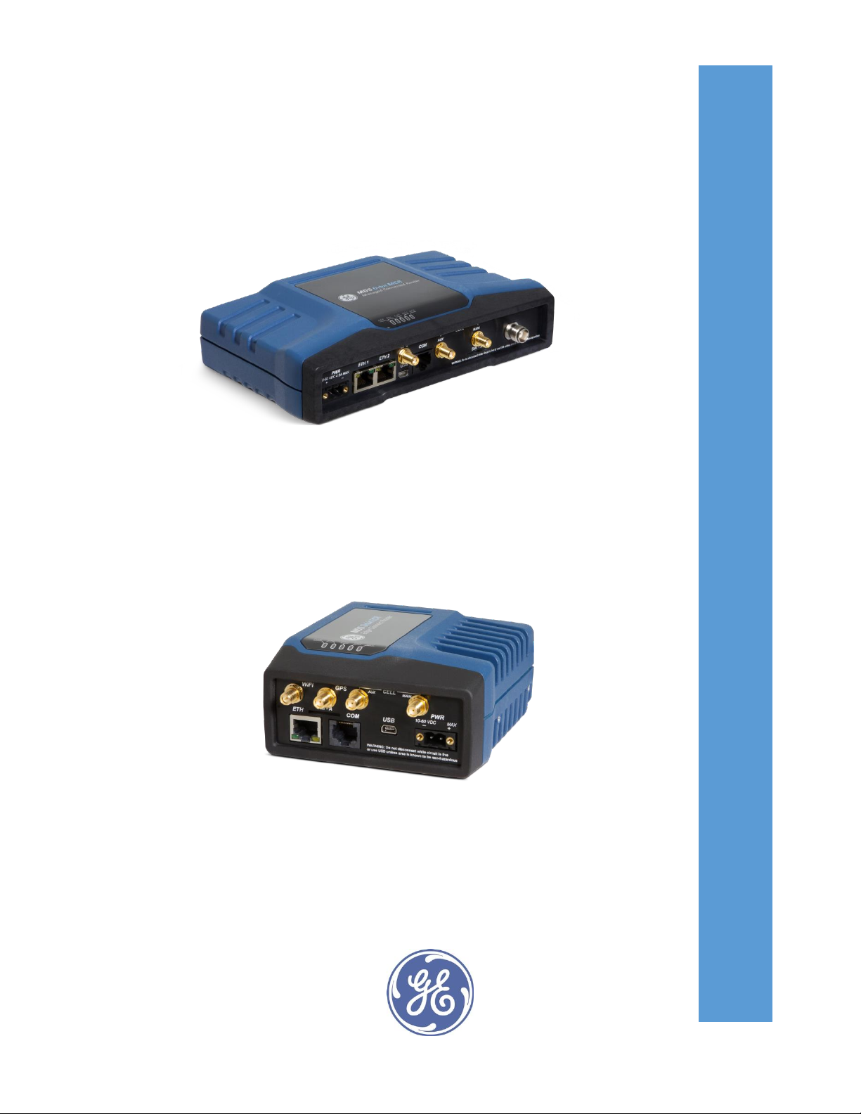
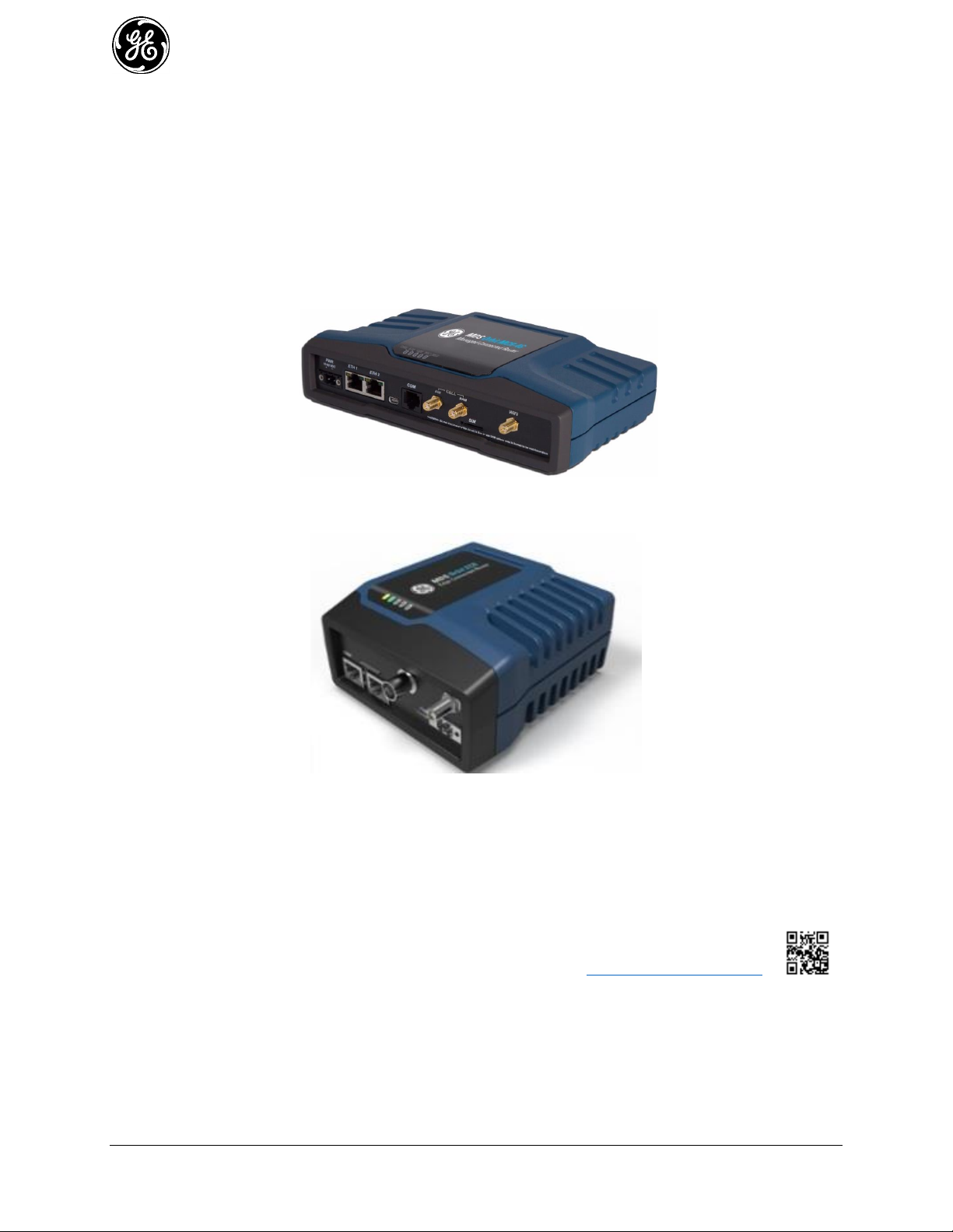
This manual describes the MDSTM Orbit Multiservice Connect Router (MCR) (Figure 1-1), and the
MDSTM Orbit Edge Connected Router (ECR) (Figure 1-2) . The unit is a highly secure, industrial grade,
wireless communication product for broad-based applications, including control center monitoring, well
site pad operations and video surveillance. It serves the need for localized WiFi communications with a
cellular back-up or backhaul option, while providing the extended temperature range and industrial-grade
packaging inherent to GE MDS products. These features allow the best use of communication options at
each installation site.
Figure 1-1. MCR-4G Unit
(Standard 2E1S configuration shown)
Figure 1-2. ECR-900 Unit
With a common hardware architecture and user interface, the MCR and ECR offers flexibility in network
design and application, with simplified training, maintenance and deployment costs. GE MDS provides
an array of communication products with multiple interface options and a variety of enclosures to give
customers the choice and flexibility to design their communications network to meet geographic and
industry specific challenges. Information on other GE MDS products can be found by visiting our website
at www.gemds.com.
GE MDS has produced a series of instructional videos for configuration and setup of the Orbit
MCR products on YouTube™. These are available free of charge at: http://tinyurl.com/pey2ull
Product Variations 1.1.1
The MDS™ Orbit MCR is factory configured with various Network Interface Cards (NICs), based on
order selection.
16 MDS Orbit MCR/ECR Technical Manual MDS 05-6632A01, Rev. G
Page 17

The label on the bottom of the unit identifies the radio model as GE MDS MCR. It includes the device
INSTALLATION & SETUP GUIDES
The Orbit MCR Setup Guide, part no. 05-6709A01 and Orbit
ECR Setup Guide, part no. 05-6709A02 contain installation
instructions, as well as basic tartup information for these
products.
All GE MDS user manuals and updates are available online at
www.gemds.com
serial number and agency/regulatory identifications, including IDs for applicable embedded modules. See
“Agency/Regulatory Approvals” on Page 395 for more information.
Orbit MCR devices with specific network interfaces may be referred to with the common names below:
MCR-4G — Name for the product when configured with 4G/LTE (Verizon ONLY).
MCR-4GS — Name for the product when configured with 4G/LTE (EMEA/APAC)
MCR-4GN — Name for the product when configured with 4G/LTE (North America).
MCR-3G — Name for the product when configured with 3G.
MCR-900 — Name for the product when configured with unlicensed 900 MHz (FHSS and DTS).
MCR-LN — Name for the product when configured with licensed narrowband QAM radios.
The MDS™ Orbit ECR is factory configured with various Network Interface Cards (NICs), based on
order selection.
The label on the bottom of the unit identifies the radio model as GE MDS ECR. It includes the device
serial number and agency/regulatory identifications, including IDs for applicable embedded modules. See
“Agency/Regulatory Approvals” on Page 395 for more information.
Orbit ECR devices with specific network interfaces may be referred to with the common names below:
ECR-4G — Name for the product when configured with 4G/LTE (North America).
ECR-4GS — Name for the product when configured with 4G/LTE (EMEA/APAC)
ECR-3G — Name for the product when configured with 3G.
ECR-900 — Name for the product when configured with unlicensed 900 MHz (FHSS and DTS).
ECR-LN — Name for the product when configured with licensed narrowband QAM radios.
About This Manual 1.1.2
This manual is intended for systems engineers, network administrators and others responsible for
planning, commissioning, using and troubleshooting the wireless system. Installation steps are not
included in this publication. For installation instructions, refer to the companion Orbit MCR Setup Guide,
part no. 05-6709A01 or Orbit ECR Setup Guide, part no. 05-6709A02 Electronic copies of all user
documentation are available free of charge at www.gemds.com
Software Command Notations
The product is designed for software control via a connected PC. As such, there are no external controls
or adjustments present. To show the names of software commands, keyboard entries, or other information
displayed on a PC screen, a bolded font is used throughout the manual. In the case of tabular data
displayed on a PC screen, a variation on this font is used to maintain proper layout. See examples that
follow.
Bolded font example (used in text for software commands and keyboard entries)
MDS 05-6632A01, Rev. G MDS Orbit MCR/ECR Technical Manual 17
Page 18

Bolded font example (used to show tables displayed on a PC screen)
In the Device Management section of this manual (Page 38), there are a number of command strings
where information is presented by the unit and a reply is required from the user. In such cases,
information from the unit is shown in a non-bolded font and the user response is shown in bold. For
example:
(none) login: admin
Further, in some cases, command lines will be shown with non-bolded, italicized text contained within
the string. Such text indicates the need for user-supplied variable parameters, such as the name of an item.
For example:
% set interfaces interface myBridge type bridge
In the above example, you would enter the specific name of your bridge to complete the entry.
NOTE The LAN port should be assigned IP addresses only if it is a routed interface (that is, not in a
bridge).
NOTE The software commands and responses shown in this manual were obtained from a unit
operating in a lab environment. The information displayed may differ from field service
conditions.
18 MDS Orbit MCR/ECR Technical Manual MDS 05-6632A01, Rev. G
Page 19

2.0 Product Description
The Orbit MCR and ECR are rugged networking routers providing comprehensive solutions for
IP/Ethernet, serial and machine-to-machine wireless communication.
2.1 Key Features
MCR units include the following key features:
Security—The unit uses industry-leading security features to protect data while maintaining
compatibility with deployed infrastructures. Features include AAA user access with passwords and
lockout protection, VPN (IPSec), signed firmware, secure booting, integrity management and more.
NOTE The Orbit MCR device is designed for high security environments. As such, management of the
device does not support Telnet, but instead implements the more secure SSH protocol.
Small Form Factor—The unit is housed in a rugged enclosure suited for operation in harsh
industrial environments. It requires only protection from direct exposure to the weather and may be
easily mounted inside a NEMA enclosure for outdoor applications when required.
Network Interfaces—Several network interfaces are present to provide connectivity for a variety of
equipment and applications. Ethernet, serial and WiFi interfaces provide local connections while a
cellular interface provides access to public carrier networks.
User Interface—Multiple user interfaces are provided for configuration and monitoring of the unit.
These include local serial console, web, SSH and USB.
NOTE For units certified and installed in hazardous locations, use only the serial or Ethernet
connections on the unit’s front panel. Do not use the USB port in hazardous locations.
Network Management System— Orbit MCR is supported by GE MDS PulseNET, a Network
Management System (NMS), providing monitoring of small and large scale deployment of all GE
MDS devices.
Tamper Detection—The unit contains a 3-axis magnetometer that can be used to detect changes to
the unit’s physical environment after installation and generate notification of the change if it exceeds
configurable thresholds. See “Tamper Detection” on Page 190.
2.2 Interface Types
ECR units are provide external interfaces 1 Ethernet, 1 Serial and 1 USB.
MCR units are offered in three external interface offerings; 2 Ethernet/1 Serial (2E1S), 2 Serial/1
Ethernet (2S1E), and 4 Ethernet/2 Serial (4E2S).
The ECR and the MCR with 4E2S each only support one Network Interface Card. The MCR 2E1S
and 2S1E support two. Most information applies equally to both configurations.
2.3 Network Interface Cards (NICs)
4G LTE/CDMA (Verizon Only) 2.3.1
The 4G LTE module is capable of operation on the Verizon Wireless LTE/CDMA network (LTE 700
MHz Band 13) in the United States. The unit supports routing of TCP/UDP/IP data from the Cellular
WAN network interface to any of the other network interfaces using the IPsec VPN or network address
and port translation (NAPT) feature and to a serial port using the terminal server service. The
configuration of these use cases is specified in respective sections on VPN, Firewall and NAT and
Terminal Service.
Orbit MCR with this modem is certified for operation on Verizon Wireless LTE/CDMA (1xRTT/EVDO)
network (ODI certified) in the United States. In addition it is also certified for use with Verizon Wireless
MDS 05-6632A01, Rev. G MDS Orbit MCR/ECR Technical Manual 19
Page 20

Private Network service (PN Compliant). For more information, refer to “ APPENDIX E – Obtaining
Provisioned 4G/LTE Service (Verizon)” on Page 429.
The cellular modem inside the unit supports main (primary) and secondary antenna (for receive diversity).
The primary antenna must be installed for cell modem to register with the cellular network. It is strongly
recommended that a secondary antenna be installed for achieving a robust cellular link.
This 4G modem supports following technologies:
LTE 1900(B2), AWS (B4), 850(B5), 700 (B13), 700(B17), 1900(B25)
CDMA 1xRTT/EV-DO Rev A - 800(BC0), 1900(BC1), 800(BC10)
Orbit MCR with this modem is Verizon ODI certified for operation on 4G LTE/3G CDMA networks, in
North America - with Verizon Wireless. Orbit MCR is also compliant with Verizon Private Network
4G LTE, HSPA+, GSM/GPRS (EMEA/APAC) 2.3.2
This 4G modem supports following technologies:
LTE 2100(B1), 1800(B3), 2600(B7), 900(B8), 800(B20) MHz
GSM/GPRS/EDGE 850/900/1800/1900 MHz
UMTS/HSPA/HSPA+ 2100(B1), 1900(B2), 850(B5), 900(B8) MHz
Orbit MCR with this modem is GCF certified for operation on 4GLTE/3G GSM/UMTS networks,
primarily in EMEA and APAC countries.
4G LTE, HSPA+, GSM/GPRS (North America) 2.3.3
This 4G modem supports following technologies:
LTE 1900(B2), AWS (B4), 850(B5), 700 (B13), 700(B17), 1900(B25)
GSM/GPRS/EDGE 850/900/1800/1900 MHz
UMTS/HSPA/HSPA+ 2100(B1), 1900(B2), AWS (B4), 850(B5), 900(B8) MHz
Orbit MCR with this modem is PTCRB certified for operation on 4GLTE/3G GSM/UMTS networks,
primarily in North America - US and Canada.
This modem is also certified for operation on Verizon and Sprint networks in North America.
3G Cell 2.3.4
The 3G modem supports following technologies:
GSM/GPRS/EDGE 850/900/1800/1900 MHz
UMTS/HSPA/HSPA+ 800/850, 900, AWS1700, 1900, 2100 MHz
Orbit MCR with this modem is PTCRB and GCF certified for operation on 2G/3G GSM/UMTS networks
around the world. This modem is also certified for operation on AT&T networks in North America.
900 MHz Unlicensed 2.3.5
900 MHz unlicensed operation is provided by the NX915 module. The NX915 provides long-distance
communications with data rates ranging from 125 kbps to 1.25 Mbps, suitable to interface both Ethernet
and Serial controllers such as PLCs, RTUs and SCADA systems. The NX915 NIC utilizes a combination
of FHSS (Frequency Hopping Spread Spectrum), DTS (Digital Transmission System) and hybrid
FHSS/DTS technologies to provide dependable wireless communications.
Key Benefits
Multiple data rates to meet application range and link budget: 125 kbps, 250 kbps, 500 kbps, 1000
kbps, 1250 kbps
Up to 60 miles LOS (Line of Sight)
20 MDS Orbit MCR/ECR Technical Manual MDS 05-6632A01, Rev. G
Page 21

Single unit AP, Remote, or Store and Forward
Patent pending extremely low latency and robust proprietary Media Access Control specifically
designed for 900 MHz communications
High Reliability
- Error detection and re-transmit on error for Unicast traffic
- Repeat support for Multicast/Broadcast traffic
- Interference avoidance will not carelessly send data if a particular frequency cannot support
communications because of interference. Communications deferred until frequency becomes
available or network moves to a new frequency
Ability to skip frequency zones, useful for persistent interferes or co-located networks
Fragmentation support to minimize on-air time in noisy environments
Ad-hoc network discovery with multiple synchronization methods
Fast mode for minimizing synchronization times
Auto mode for discovering network modulation and optimal paths based on statistical analysis of the
network
Store and Forward
- Supports up to 8-hops SAF level depth.
- Supports multiple SAFs on any level.
- Automatically adjusts Media Access scheme for SAF network to support simultaneous
communications at alternating levels and minimize latency, using dynamic fragmentation.
- Supports dynamic and static paths providing flexibility in designing the wireless network.
Quality of Service (QoS)
- Priority Queues
- Source/Destination port and addresses
- Protocol (UDP, TCP, etc.)
Licensed Narrowband 2.3.6
Licensed Narrowband operation is provided by the LN series NIC modules. Licensed Narrowband
modules provide robust long-distance communication in channel bandwidth sizes of 6.25KHz, 12.5KHz,
and 25KHz using QAM and FSK technology.
LN modules provide suitable options to interface both Ethernet and Serial controllers such as PLCs,
RTUs and SCADA systems. For QAM operation, depending on bandwidth, raw data rates range from
20kbps to 120kbps.
Key Benefits
Bi-Directional Adaptive QAM Modulation (QPSK, 16QAM, 64QAM)
Backward Compatible supporting substitution for Legacy remotes including x710A/C/M and SD
(using equivalent X710 modems, operating in both transparent-serial and packet-with-mac modes)
Up to 50 miles LOS (Line of Sight)
Single unit AP or Remote
Store and Forward
Low latency and robust proprietary Media Access Control specifically designed narrowband
communications
MDS 05-6632A01, Rev. G MDS Orbit MCR/ECR Technical Manual 21
Page 22
High Reliability
- Error detection and re-transmit on error for Unicast traffic
- Multiple Forward Error Correction (FEC) modes including adaptive FEC
Quality of Service (QoS)
- Priority Queues
- Source/Destination port and addresses
- Protocol (UDP, TCP, etc.)
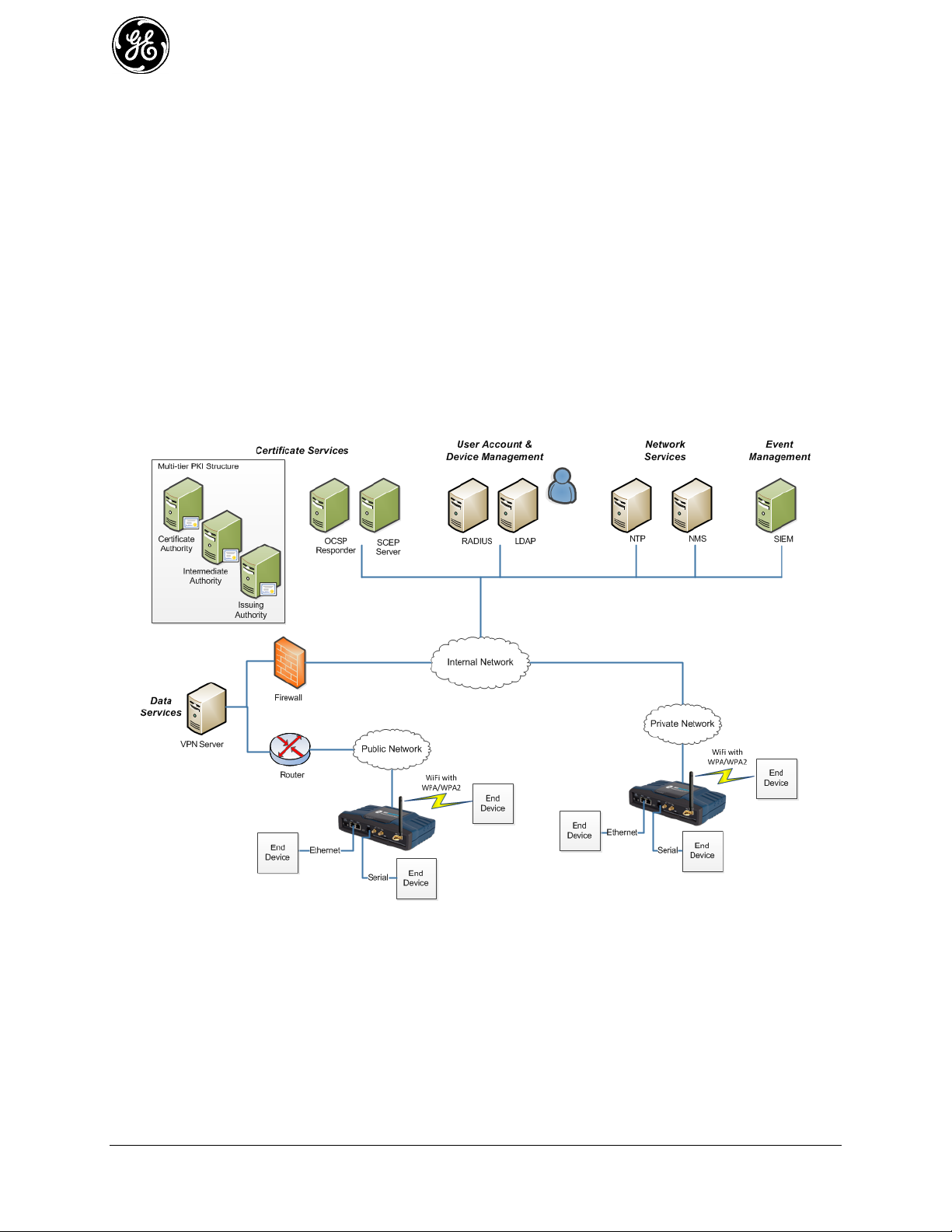
2.4 Typical Applications
The unit provides flexibility in network communications and may be used in a wide variety of
applications. In one common scenario, it provides cellular connectivity to locally-connected devices that
are located on a local/internal/private LAN or WiFi network. The unit acts as an Access Point on the WiFi
interface to provide connectivity to WiFi clients. Figure 2-1 shows an example network in which the unit
provides connectivity to multiple end devices. The end devices are connected via Ethernet, serial and
WiFi links.
Figure 2-1. Typical MCR Application
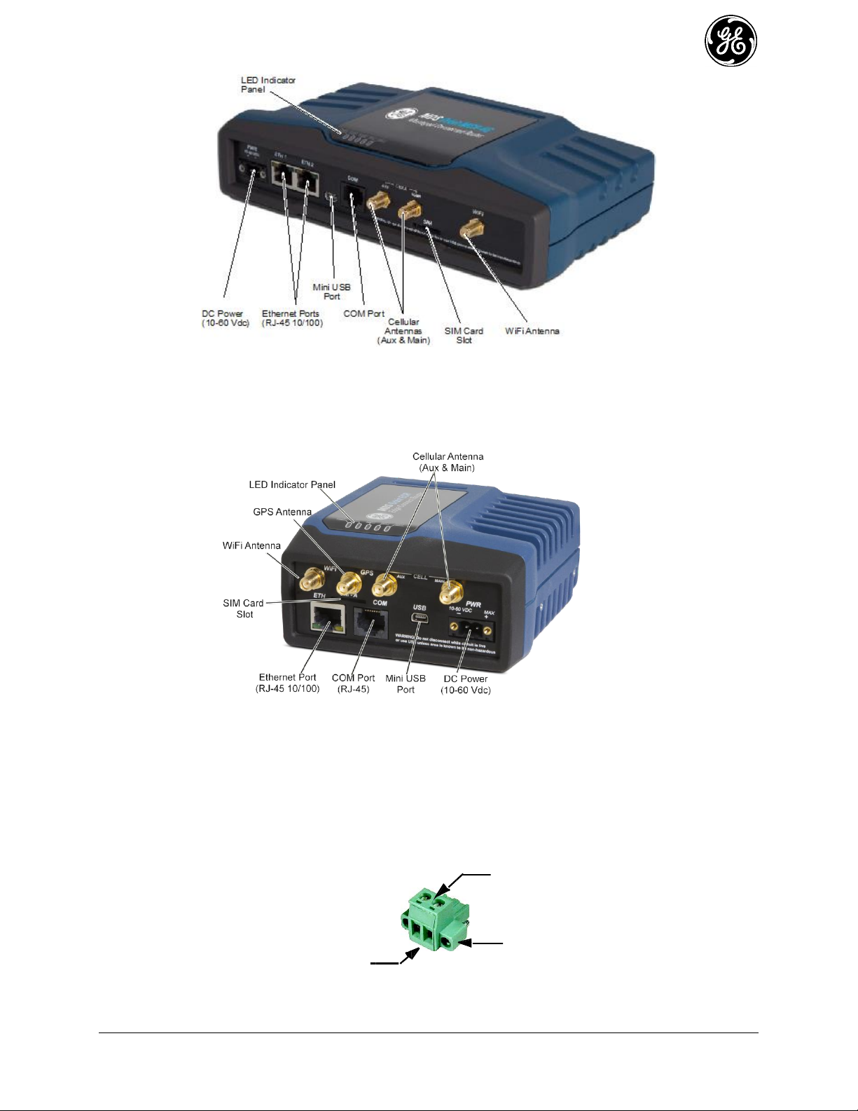
2.5 MCR and ECR Connectors and Indicators
Figure 2-2 shows the unit’s front panel connectors and indicators. These items are referenced in the text
that follows. The unit’s LED Indicator Panel is described in Table 2-5.
.
22 MDS Orbit MCR/ECR Technical Manual MDS 05-6632A01, Rev. G
Page 23
Lead
Screws (2)
Binding
Wire Ports (2)
(Polarity: Left +, Right –)
Retaining
Screws (2)
Figure 2-2. MCR Connectors and Indicators
(Sample configuration with Cell, WiFi, two Ethernet and one Serial port)
Figure 2-3 shows the unit’s front panel connectors and indicators. These items are referenced in the text
that follows. The unit’s LED Indicator Panel is described in Table 2-5.
PWR—Two-conductor DC input connection .
MDS 05-6632A01, Rev. G MDS Orbit MCR/ECR Technical Manual 23
Figure 2-3. ECR Connectors and Indicators
(Sample configuration with Cell, WiFi, Ethernet and Serial port)
- The DC power connector (Figure 2-4) is keyed and can only be inserted one way.
- Use Copper Conductors Only
- Use 18 AWG wire
- Tighten wire clamps to 5 lb-in. (0.6 Nm)
Figure 2-4. DC Power Connector (P/N 73-1194A39)
Page 24

Table 2-1. ETH1/2 Pin Details
Pin
Function
Pin
Function
1
Transmit Data (TX) High
5
Unused
2
Transmit Data (TX) Low
6
Receive Data (RX) Low
3
Receive Data (RX) High
7
Unused
4
Unused
8
Unused
NOTE The unit is designed for use in negative ground DC power systems only. Only use the power
supply provided by the manufacturer for the product or a certified LPS power supply rated for
nominal power 11-55 VDC, 4.5 A maximum must be used. Otherwise, safety of the product
may be impaired. In case of doubt, please consult the local authorized suppliers.
Input voltage to the unit must be well filtered and within the nominal range of 11-55 VDC . The
maximum rated power consumption of the device is 15 watts, but actual power may be much less,
depending on configuration. The power supply must be capable of supplying the expected maximum
power for the installation. For expected power requirements in common configurations, see “Technical
Specifications” on Page 393.
ETH1 / ETH2— Ethernet connection port. These ports support both device management and payload
data transport. Depending on ordered options, the unit may have one or two Ethernet ports. This is a
standard RJ-45 jack and features MDIX auto-sensing capability, allowing straight-through or crossover
cables to be used.
Connecting to the unit via SSH supports device management and provides the same user interface
available using the unit’s COM1 serial port. Various options are available for passing Ethernet data,
allowing system administrators to optimize the configuration for maximum efficiency, based on the
system’s operating characteristics.
(As viewed from the outside the unit)
USB Port—This port allows for connection of a laptop or PC. The port provides a local console for
management of the device. A standard host-to-mini device USB 2.0 cable may be used.
COM1/COM2 Port—This connector serves as the serial interface port for both console management and
payload data. Depending on ordered options, the unit may have one or two COM ports. By default, the
port is enabled for local console control. The COM port serves as the primary interface for connecting the
unit to an external DTE serial device supporting RS-232 or RS-485. If necessary, an adapter may be used
to convert the unit’s RJ-45 serial jack to a DB-9F type (GE MDS 73-2434A25).
NOTE Not all PCs include a serial port. If one is not available, the unit’s USB port may be used to
access the device management interface. Alternatively, a PC’s USB port may be used with a
USB-to-Serial adapter and appropriate driver software. These devices are available from several
manufacturers. A video covering USB driver installation may be accessed from the following
link: http://tinyurl.com/pey2ull
The COM port supports a serial data rate of 1200-230400 bps (115200 default, asynchronous only). The
unit is hardwired as a DCE device. Supported data formats for the COM port are:
24 MDS Orbit MCR/ECR Technical Manual MDS 05-6632A01, Rev. G
8N1 - 8 char bits, no parity, 1 stop bit (Default setting)
8N2 - 8 char bits, no parity, 2 stop bits
Page 25

8O1 - 8 char bits, odd parity, 1 stop bit
Pin
Number
Input / Output
Pin Description
1
OUT
COM1 only: ALARM Output (refer to “Alarms” on Page 162 )
2
OUT
DCD (Data Carrier Detect)
3
Reserved
--
4
Ground
Connects to ground (negative supply potential) on chassis
5
OUT
RXD (Received Data)—Supplies received data to the connected device
6
IN
TXD (Transmitted Data)—Accepts TX data from the connected device
7
OUT
CTS (Clear to Send)
8
IN
RTS (Request to Send)
8O2 - 8 char bits, odd parity, 2 stop bits
8E1 - 8 char bits, even parity, 1 stop bit
8E2 - 8 char bits, even parity, 2 stop bits
7N1 - 7 char bits, no parity, 1 stop bit
7N2 - 7 char bits, no parity, 2 stop bits
7O1 - 7 char bits, odd parity, 1 stop bit
7O2 - 7 char bits, odd parity, 2 stop bits
7E1 - 7 char bits, even parity, 1 stop bit
7E2 - 7 char bits, even parity, 2 stop bits.
The tables on the following page provide pin descriptions for the COM1 data port in RS-232 mode and
RS-485 modes, respectively.
NOTE The COM2 port, if present, is restricted to RS-232 mode; it cannot be used for RS-485.
(As viewed from the outside the unit)
Table 2-2. COM1/2 Port Pin Details (RS-232)
MDS 05-6632A01, Rev. G MDS Orbit MCR/ECR Technical Manual 25
Page 26
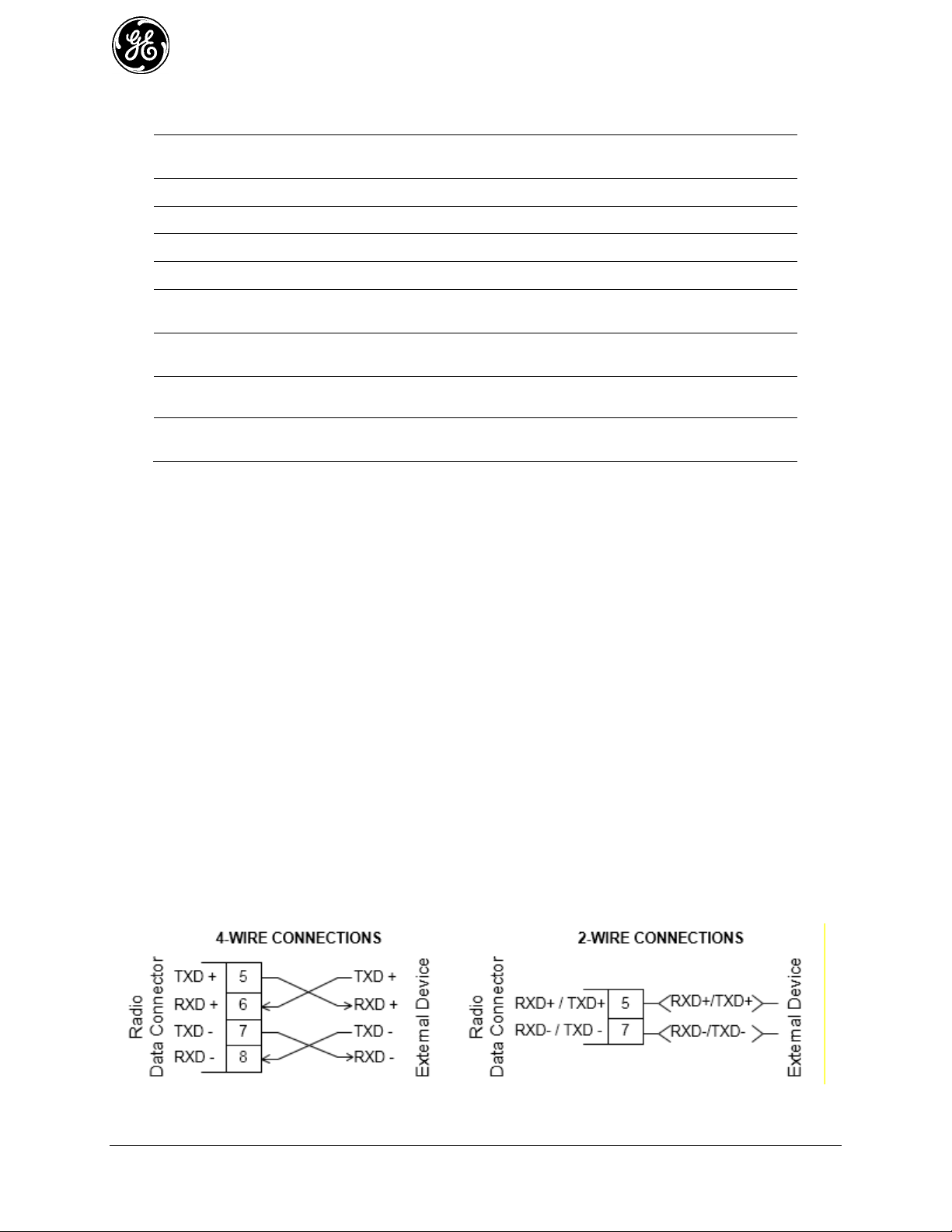
Table 2-3. COM1 Port Pin Details (RS-485)
Pin
Number
Input/Output
Pin Description
1
OUT
ALARM Output (refer to “Alarms” on Page 162)
2
OUT
DCD (Data Carrier Detect)
3
Reserved
-- 4 Ground
Connects to ground (negative supply potential) on chassis
5
OUT
TXD+/TXB (Transmitted Data +)—Non-inverting driver output. Supplies
received payload data to the connected device.
6
IN
RXD+/RXB (Received Data +) — Non-inverting receiver input. Accepts
payload data from the connected device.
7
OUT
TXD-/TXA (Transmitted Data -)—Inverting driver output. Supplies
received payload data to the connected device.
8
IN
RXD-/RXA (Received Data -) — Inverting receiver input. Accepts
payload data from the connected device.
COM1 Port notes and wiring arrangements (for RS-485)
The COM1 port supports 4-wire and 2-wire RS-485 mode as follows:
- RXD+ / RXB and RXD– / RXA are data sent into the unit
- RXD+ / RXB is positive with respect to RXD– / RXA when the line input is a “0”
- TXD+ / TXB and TXD– / TXA are data sent out by the unit
- TXD+ / TXB is positive with respect to the TXD– / TXA when the line output is a “0”
2-wire RS-485 mode connections:
- Connect pins 5&6 (TXD+/RXD+) together and connect to (TXD+/RXD+) tied together on
connected device
- Connect pins 7&8 (RXD-/TXD-) together and connect to (TXD-/RXD-) tied together on
connected device
4-wire RS-485 mode connections:
- Connect pin 5 (TXD+) to RXD+ of connected device
- Connect pin 6 (RXD+) to TXD+ of connected device
- Connect pin 7 (TXD-) to RXD- of connected device
- Connect pin 8 (RXD-) to TXD- of connected device
Figure 2-5 illustrates the 2-wire and 4-wire connections described above.
Figure 2-5. EIA-485 4-Wire/2-Wire Connections
26 MDS Orbit MCR/ECR Technical Manual MDS 05-6632A01, Rev. G
Page 27
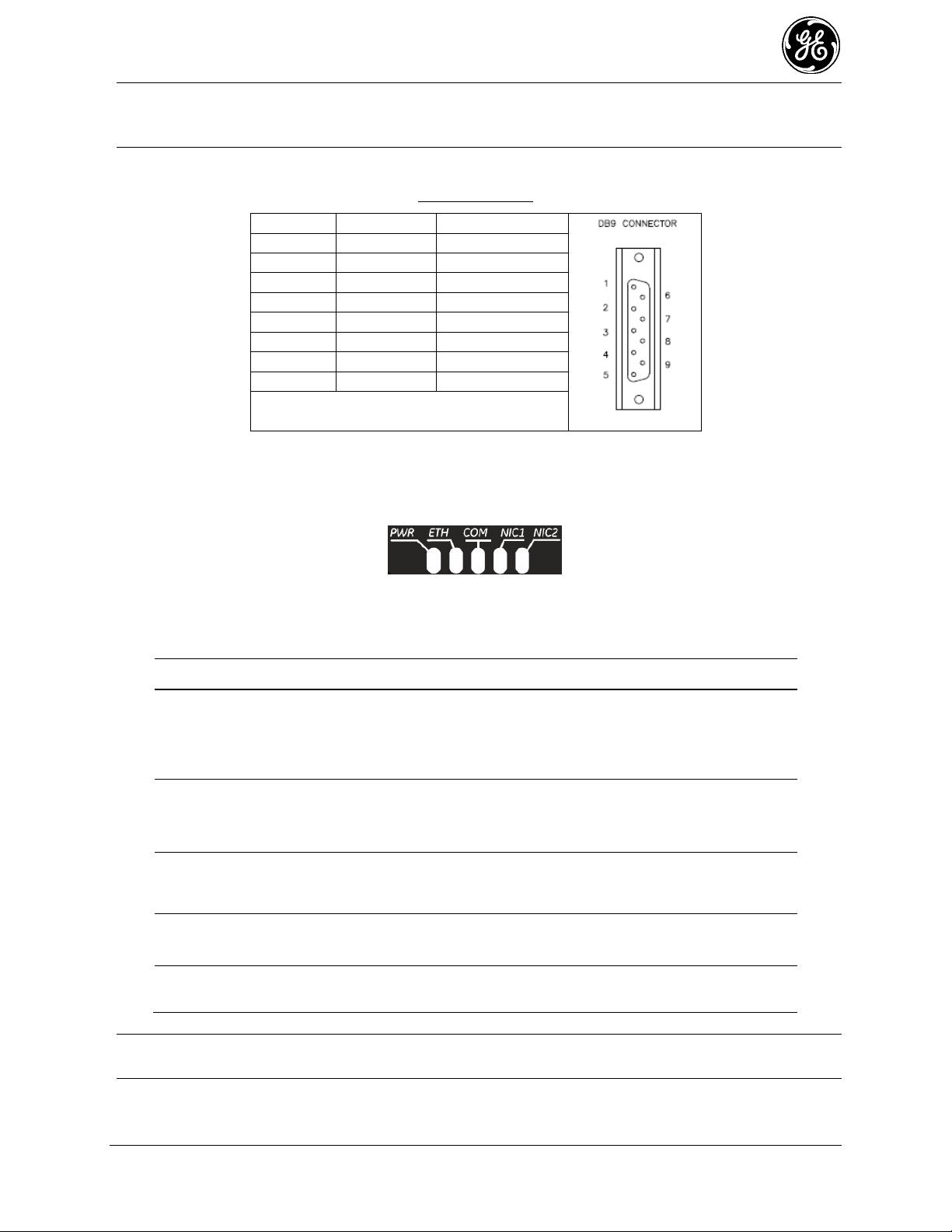
NOTE GE MDS part number 73-2434A25 provides a custom RJ45 to DB9 Adapter for use with the
RJ-45 PIN
FUNCTION
DB9 PIN
1
DSR
6
2
DCD 1 3
DTR
4
4
GND 5 5
RXD 2 6
TXD 3 7
CTS 8 8
RTS
7
Table 2-4. Description of LED Status Indicators
LED Name
LED State
Description
PWR
(DC Power)
Off
Solid Green
Fast Blink/Red (1x/sec.)
No power to unit
Unit is powered, no problems detected
Alarm indication
ETH
(Ethernet)
Off
Solid Green
Blinking Green
No Ethernet link to network
Ethernet link present
Ethernet traffic in/out
COM
(Serial Comm. Port)
Off
Blinking Green
No serial connection, or idle
Serial traffic in/out
NIC1
Off
Green
Interface disabled
Interface enabled/working
NIC2
Off
Green
Interface disabled
Interface enabled/working
Orbit MCR and other GE MDS products. The chart below provides details for connections
made using this adapter.
WIRING CHART
LED Status Indicators—The LEDs on the unit provide visual indications of the status of the device as
shown in the following chart:
Figure 2-6. LED Status Indicators
NOTE In addition to the LEDs above, the Ethernet connector has two embedded LEDs. A yellow
indicates a link at 100 Mbps operation. A flashing green indicates Ethernet data traffic.
MDS 05-6632A01, Rev. G MDS Orbit MCR/ECR Technical Manual 27
Page 28

Product Configuration
NIC1
NIC2
MCR-4G + WiFi
Cellular
WiFi
MCR-4G Only
Cellular
Off
MCR-3G + WiFi
Cellular
WiFi
MCR-3G Only
Cellular
Off
MCR-WiFi only
Off
WiFi
MCR-900 + 4G
Cellular
900 ISM (NxRadio)
MCR-900 + WiFi
WiFi
900 ISM (NxRadio)
MCR-900 + 3G
Cellular
900 ISM (NxRadio)
MCR-900 Only
Off
900 ISM (NxRadio)
MCR-LN + 3G
Cellular
Lic. Narrowband (LnRadio)
MCR-LN + WiFi
WiFi
Lic. Narrowband (LnRadio)
MCR-LN + 3G
Cellular
Lic. Narrowband (LnRadio)
MCR-LN Only
Off
Lic. Narrowband (LnRadio)
Product Configuration
NIC1
NIC2
ECR-4G + WiFi
WiFi
Cellular
ECR-4G Only
Off
Cellular
ECR-3G + WiFi
WiFi
Cellular
ECR-3G Only
Off
Cellular
ECR-WiFi only
WiFi
Off
ECR-900 + WiFi
WiFi
900 ISM (NxRadio)
ECR-900 Only
Off
900 ISM (NxRadio)
ECR-LN + WiFi
WiFi
Lic. Narrowband (LnRadio)
ECR-LN Only
Off
Lic. Narrowband (LnRadio)
Depending on the interfaces ordered, the NIC1 and NIC2 slot can be populated with a Cellular modem, a
WiFi interface, LnRadio interface, or an NxRadio interface. LED associations for NIC1 and NIC2 follow
the physical left-to-right order of the physical connector positions as labeled on the faceplate.
See detail described in Table 2-5 and Table 2-6 below, based on the product configuration ordered.
Table 2-5. MCR NIC LED Descriptions
Table 2-6. ECR NIC LED Descriptions
2.6 Grounding Considerations
To minimize the chance of damage to the unit and its connected equipment, a safety ground (NEC Class 2
compliant) is recommended, which bonds the chassis, antenna system(s), power supply and connected
data equipment to a single-point ground, keeping all ground leads as short as possible.
28 MDS Orbit MCR/ECR Technical Manual MDS 05-6632A01, Rev. G
Page 29

Normally, the unit is adequately grounded if mounted with the flat brackets to a well-grounded metal
5.3" 1.0" (2X)
.75" (2X)
6-32 Screw (6X)
Tap in Enclosure
2.75" (2X)
4.81"
9.25"
8.5"
1.5" (2X)
8.0"
2.65"
surface. If the unit is not mounted to a grounded surface, it is recommended that a safety ground wire be
attached to the screw provided on the bottom corner of the enclosure, in the recessed flat area.
Alternatively, a safety ground wire may be attached to one of the mounting bracket screws.
The use of a lightning protector is recommended where the antenna cable enters the building; Bond the
protector to the tower ground, if possible. All grounds and cabling must comply with applicable codes
and regulations. One source for lightning protection products may be found online at
http://www.protectiongroup.com/PolyPhaser.
2.7 Mounting Options
The unit may be mounted with flat mounting brackets or an optional 35 mm DIN rail attachment. Figure
2-7 shows the mounting dimensions for a unit equipped with flat mounting brackets.
Figure 2-7. MCR Flat Mounting Bracket Dimensions
MDS 05-6632A01, Rev. G MDS Orbit MCR/ECR Technical Manual 29
Page 30
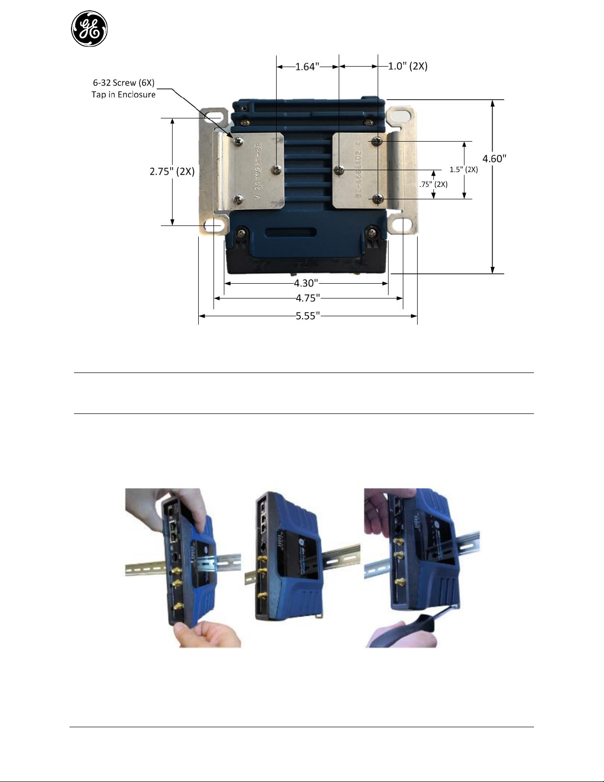
Figure 2-8. ECR Flat Mounting Bracket Dimensions
NOTE To prevent moisture from entering the unit, do not mount the case with the cable connectors
pointing up. Also, dress all cables to prevent moisture from running along the cables and into
the unit.
Optional DIN Rail Mounting 2.7.1
If ordered with the DIN rail mounting option, the unit is supplied with a DIN rail clip attached to the case.
The integrated bracket on the unit’s case allows for quick installation and removal from a DIN mounting
rail as shown in Figure 2-9.
Figure 2-9. DIN Rail Attachment and Removal
(Pull down tab to release from rail)
30 MDS Orbit MCR/ECR Technical Manual MDS 05-6632A01, Rev. G
Page 31

2.8 Antenna Planning and Installation
Consideration must be taken to select appropriate antennas for optimal RF performance. This section
reviews the key factors involved in selecting and installing antennas for the Orbit MCR and ECR. Only
approved antennas may be used on the unit’s RF output connectors. These antennas are listed in each
applicable section for each RF type. The use of non-approved antennas may result in a violation of FCC
rules and subject the user to FCC enforcement action. Note that with any installation, there needs to be a
minimum 20 cm spacing between all transmit antennas to avoid co-location difficulties.
Cell Antennas (Aux and Main)—These SMA coaxial connectors are for attachment of cellular antennas.
The MAIN connection is for basic cellular transmission/reception and the AUX connector is for
attachment of a receive-only antenna which provides MIMO receive operation (diversity) with standard
Cell modules, improving signal quality in many installations. In general, both antennas should always be
used for cellular operation. The GE MDS part number for this antenna type is 97-2485A04.
Figure 2-10. Directly-Connected Cellular Antenna (Typical Style)
(GE MDS Part No. 97-2485A04)
WiFi Antenna—Antenna connection for 2.4 GHz WiFi service. The connector appears similar to the
cellular connectors discussed above, but is a Reverse-SMA type. It contains a pin that matches with an
SMA-F connector. The GE MDS part number for this antenna is 97-4278A34.
To connect an external WiFi antenna, 97-4278A48, a Reverse SMA to N-Female cable and antenna
mount is required. These are not sold from GE MDS but are available from many retailers.
900 MHz ISM Antennas —Antenna connection is a TNC connector. Multiple options are available for
this unlicensed operation.
NOTE For 900MHz ISM operation (NX915 NIC) professional installation is required.
NOTE For Australia and New Zealand the maximum EIRP must be limited to 30 dBm. If ((antenna
gain - feed line loss) + power output setting) > 30), then the power output of the
NX915 must be reduced.
NOTE For regions governed by FCC/IC compliance the maximum EIRP must be limited to 36 dBm. If
((antenna gain - feed line loss) + power output setting) >36), then the power
output of the NX915 must be reduced.
MDS 05-6632A01, Rev. G MDS Orbit MCR/ECR Technical Manual 31
Page 32

Table 2-7. Special Accessories for 900MHz ISM
Item
Description
Part Number
Bandpass Filter
Antenna system filter that helps
eliminate interference from nearby
paging transmitters.
20-2822A02
Licensed Narrowband Antennas —Antenna connection is a TNC connector. Multiple options are
available based on radio type and site-specific licensing rules.
32 MDS Orbit MCR/ECR Technical Manual MDS 05-6632A01, Rev. G
Page 33

Antenna Type and Orientation (Cell & Wi-Fi)
It is important to use antennas designed to operate in the applicable cellular coverage bands with a Return
Loss of 10 dB or better. Placement of the antennas also plays a key role in the coverage of the system.
While the antennas can be placed directly on the face of the unit in some short range installations, the best
performance is obtained when mounting antennas remotely using low loss coaxial cable. Antennas
mounted in close proximity to each other can couple signals between them and desensitize the RF
module.
When placing the indoor SMA style “paddle” antennas on the face of the unit, position them with a 90
degree angle of separation to improve the isolation. A “V” or an “L” configuration is a common approach
to use with the Main channel typically mounted for vertical polarization. The multipath nature of Cellular
systems means that polarization for indoor use is not normally a critical factor. Isolation between the
antennas is more important.
Indoor use case:
This scenario employs direct mounting of an LTE paddle antenna (GE MDS PN: 97-2485A04) on the
Main and Aux Cell channels and cabled mounting of the Wi-Fi antenna (GE MDS PN: 97-4278A34)
using a magnetic mount (GE MDS PN: 97-4278A78). This configuration offers easy mobility for
evaluation purposes or indoor applications with good cellular signal coverage (see Figure 2-11).
Figure 2-11. Direct Mounting of Cell Antenna; Cabled WiFi Antenna
Minimum 8-inch (20.32 cm) separation between cell and WiFi antennas
This arrangement employs cabled mounting of the LTE paddle antennas (GE MDS 97-2485A04) on the
Main and AUX Cell channels and cabled mounting of the Wi-Fi antenna (GE MDS 97-4278A34) using a
magnetic mount (GE MDS 97-4278A78). The Wi-Fi antenna may also be directly attached to the unit, if
desired. This configuration works well for indoor installations in equipment closets, or for more
permanent applications.
Outdoor use case:
External enclosures—If the system is going to be installed in a weathertight enclosure and mounted
outside in the elements, cabled use of external LTE antennas (GE MDS PN: 97-2485A05) on the Main
and AUX Cell ports, with cabled use of the External Wi-Fi antenna (GE MDS PN: 97-4278A48) is a
good solution. This configuration requires a suitable metallic ground plane for the Cellular antennas (8"
diameter disc minimum for the 97-2485A05 series) or a suitable counterpoise for frequencies as low as
698 MHz Metal enclosures work well for ground plane requirements, when ground contact inside the box
is not impeded by painted surfaces.
Do not use internally mounted antennas inside of metal enclosures.
Other antenna configurations can be easily customized for applications not listed here. Consult your
factory representative for installation matters.
MDS 05-6632A01, Rev. G MDS Orbit MCR/ECR Technical Manual 33
Page 34

Cable Type
10 Feet
(3 Meters)
50 Feet
(15 Meters)
100 Feet
(30.5 Meters)
200 Feet
(61 Meters)
RG-8A/U
0.51 dB
2.53 dB
5.07 dB
10.14 dB
½ inch HELIAX
0.12 dB
0.76 dB
1.51 dB
3.02 dB
7/8 inch HELIAX
0.08 dB
0.42 dB
0.83 dB
1.66 dB
1-1/4 inch HELIAX
0.06 dB
0.31 dB
0.62 dB
1.24 dB
1-5/8 inch HELIAX
0.05 dB
0.26 dB
0.52 dB
1.04 dB
Antenna Installation Guidance (Licensed Narrowband)
Antennas:
LN transceivers may be used with a number of different antennas. The exact style and gain factor depend
on regulatory constraints and the physical size/layout of your system. Connection is made to the radio via
a TNC coaxial connector. A directional Yagi (Figure 2-12) or corner reflector antenna is generally used at
remote sites to minimize interference to and from other users. Antennas of this type are available from
several manufacturers, including GE MDS. Contact your sales representative for details.
Figure 2-12. Typical Yagi Antenna (mounted to mast)
Feedlines:
Selection of an antenna feedline is very important. Poor quality cable should be avoided as it will result in
power losses that may reduce the range and reliability of the radio system. The tables which follow show
the approximate losses that will occur when using various lengths and types of coaxial cable. Regardless
of the type used, the cable should be kept as short as possible to minimize signal loss.
Table 2-8. Signal Loss In Coaxial Cables (at 400 MHz)
34 MDS Orbit MCR/ECR Technical Manual MDS 05-6632A01, Rev. G
Page 35

Cable Type
10 Feet
(3 Meters)
50 Feet
(15 Meters)
100 Feet
(30.5 Meters)
200 Feet
(61 Meters)
½ inch HELIAX
0.20 dB
0.98 dB
1.96 dB
3.91 dB
7/8 inch HELIAX
0.11 dB
0.55 dB
1.10 dB
2.19 dB
1-1/4 inch HELIAX
0.08 dB
0.39 dB
0.78 dB
1.57 dB
Cable Type
10 Feet
(3 Meters)
50 Feet
(15 Meters)
100 Feet
(30.5 Meters)
500 Feet
(152 Meters)
RG-214
0.76 dB
3.80 dB
7.60 dB
Unacceptable Loss
LMR-400
0.39 dB
1.95 dB
3.90 dB
Unacceptable Loss
1/2 inch HELIAX
0.23 dB
1.15 dB
2.29 dB
11.45 dB
7/8 inch HELIAX
0.13 dB
0.64 dB
1.28 dB
6.40 dB
1-1/4 inch HELIAX
0.10 dB
0.48 dB
0.95 dB
4.75 dB
1-5/8 inch HELIAX
0.08 dB
0.40 dB
0.80 dB
4.00 dB
Table 2-11. Accessories & Ancillary Items
Item
Description
Part Number
DC Power Plug, 2-pin, polarized
Mates with power connector on the
unit’s case. Screw terminals are
provided for wires, threaded locking
screws to prevent accidental
disconnect.
73-1194A53
Setup Guide
(for installation instructions)
Describes the installation and setup
of the unit. It is a companion to this
Technical Manual. PDF copy
available free at www.gemds.com.
05-6709A01
Flat Mounting Bracket Kit
Brackets that attach to the bottom
of the unit, used for mounting to a
flat mounting surface.
03-4123A14
COM Port Adapter
Converts the unit’s RJ-45 serial jack
to a DB-9F type.
73-2434A25
Table 2-9. Signal Loss In Coaxial Cables (at 700 MHz)
Table 2-10. Signal Loss In Coaxial Cables (at 900 MHz)
Accessories and Spares
The table below lists common accessories and spare items for use with the MCR. GE MDS also offers an
Accessories Selection Guide listing an array of additional items that may be used with the product.
Contact your factory representative or visit www.gemds.com to obtain a copy of the guide.
MDS 05-6632A01, Rev. G MDS Orbit MCR/ECR Technical Manual 35
Page 36

Table 2-11. Accessories & Ancillary Items
Item
Description
Part Number
Ethernet Surge Suppressor
Surge suppressor for protection of
the Ethernet port against lightning.
29-4018A01
Mini USB 2.0 Cable, 3 ft
USB Type A (M) to mini-USB Type
B (M) cable to provide console
access through the radio’s mini
USB connector.
97-6694A05
DIN Rail Mounting Kit
Hardware for DIN Rail Mounting
03-4125A06
36 MDS Orbit MCR/ECR Technical Manual MDS 05-6632A01, Rev. G
Page 37

MDS 05-6632A01, Rev. G MDS Orbit MCR/ECR Technical Manual 37
Page 38

3.0 Device Management
This section describes the steps for connecting a PC, logging in and setting unit parameters. The focus
here is on the local serial console interface, but other methods of connection are available and offer
similar capabilities. The key differences are with initial access and appearance of data.
The MCR offers several interfaces to allow device configuration and monitoring of status and
performance. These include local serial console, USB, NETCONF, HTTPS and Secure Shell (SSH) for
local and remote access via the WAN and LAN networks. The serial console, USB and SSH services
offer a command line interface (CLI). There are three user accounts/roles for management access: admin,
tech and oper. User accounts can be centrally managed with a RADIUS server. RADIUS accounts can be
mapped to one of the three user accounts/roles (See “User Management and Access Controls” on Page
176).
NOTE The Orbit MCR device is designed for high security environments. As such, management of the
device does not support Telnet, but instead implements the more secure SSH protocol.
Configuring and managing the Orbit MCR is done by changing configuration data via the Web User
Interface (UI) or from the Command Line Interface (CLI). Either way requires two steps. The first step is
to use a user interface to add, remove, or alter a piece of configuration data. The second step is to use the
user interface to commit the change. Multiple changes can be made prior to committing them. This twostep process allows users to make multiple changes to the configuration and apply them in a bulk commit.
Additionally, the device can validate the bulk commit and reject it if there is an error.
The Device Manager is a built-in software tool that works with your PC’s browser to provide an intuitive,
web-style presentation of all unit information, settings, and diagnostics. Web management uses the unit’s
Ethernet RJ-45 connector
NOTE For security, web access can be enabled/disabled via the CLI using the command: % set
services web http(s) enabled true/false
To connect to the unit and manage it via the Device Manager, you will need the following:
A PC with a web browser program installed.
An Ethernet cable connected between the PC and the MCR as shown in PC Connection for
Web Management.
The unit’s IP address. Check with your Network Administrator, or determine the address via a
command line interface connection. The default address for a factory supplied unit is
192.168.1.1.
The user name and password for the unit. Check with your Network Administrator, or, if a
username and password have not been set, use the factory defaults of admin for both entries.
(For security, a new password should be established as soon as possible after login.)
Figure 3-1. PC Connection for Web Management
Use of a modern browser is highly recommended.
38 MDS Orbit MCR/ECR Technical Manual MDS 05-6632A01, Rev. G
Page 39

Table 3-1. Browser Support
Browser Type
Version
Microsoft ™ Internet Explorer
10.x or newer
Mozilla Firefox
39.0 or newer
Apple Safari (Mac OS X only)
10.0 or newer
Google Chrome
26.x or newer
Logging On
Connect the unit to a PC via an Ethernet connection. 1.
Configure your PC network settings to an IP address on the same subnet as the unit. The default 2.
subnet mask is 255.255.255.0.
NOTE For IP addressing the Orbit MCR uses a routing prefix expressed in CIDR notation instead of
the specifying a subnet mask. The CIDR notation is the first address of a network, followed by
a slash character (/), and ending with the bit-length (max 32) of the prefix. A subnet mask is
expressed in dot-decimal notation. For example, 192.168.1.0/24 is equivalent to specifying
192.168.1.0 with a subnet mask of 255.255.255.0.
Enter the unit’s IP address in a web browser window, just as you would enter a website address. 3.
When the login screen appears (Figure 3-2. Login Screen), enter the User Name and Password for
the unit. The default entries for a new unit are both admin. Click OK.
Figure 3-2. Login Screen
Getting an Overview of Unit Settings
To get a top-level view of the key settings and operating parameters for the unit, select Home in the upper
left hand side of the screen and a summary screen will be displayed. When finished, log out of the Device
Manager by clicking Logout in the upper right hand side of the screen.
MDS 05-6632A01, Rev. G MDS Orbit MCR/ECR Technical Manual 39
Page 40
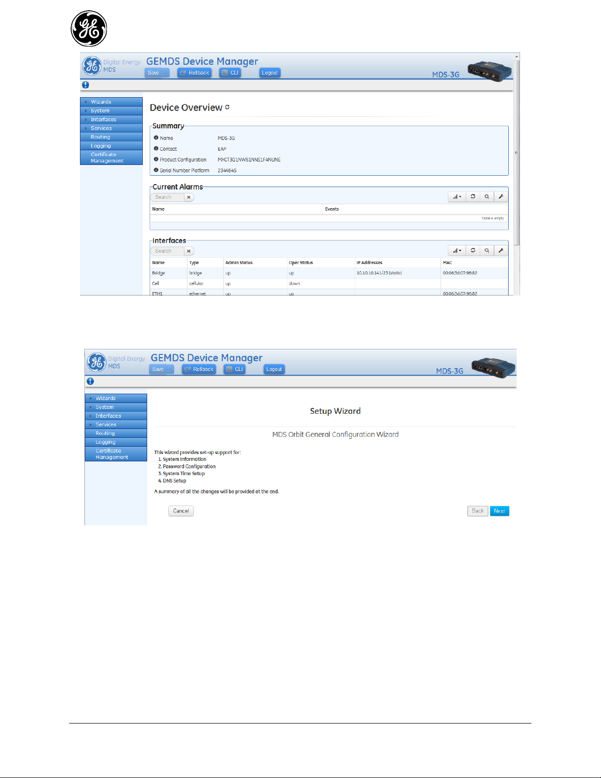
Figure 3-3. Device Manager, Overview Screen
For initial configuration, the Setup Wizard will appear and provide guidance in typical setups. This will
be disabled after initial setup is completed, but may be re-run at any time from the Wizards page.
Figure 3-4. Initial Setup Wizard Starting Page
40 MDS Orbit MCR/ECR Technical Manual MDS 05-6632A01, Rev. G
Page 41

In addition to the Setup Wizard other Configuration Wizards are available to assist Services and
Networking. The Basic Interface Setup wizard can be particularly helpful for initial device configuration.
From the Web UI changes made on the screens are not saved or implemented until via the save button or
commit command. The Save button in the banner on the top left of every page. Normally this is not
highlighted and blue in color as shown below:
Figure 3-5. Save Button—No changes to commit
When there are changes to commit, the button is highlighted and colored green. Options available are:
View, Validate and Cancel. Clicking the button defaults to Validate and saves the changes.
Figure 3-6. Save Button—Changes to commit
From the CLI, all changes are made and committed using by using the commit command and enter.
% commit
3.1 Initial Settings Overview
Setting Basic Parameters—First Steps 3.1.1
There are three tasks that should be performed after initial startup and connection to a PC, as follows:
Create One-Time Programmable passwords for device recovery in the event a password is lost. 1.
Change the login passwords. 2.
Evaluate the default factory configuration and set it to the user's required security level. 3.
One-Time “Recovery” Passwords 3.1.2
The MDS Orbit platform employs extensive security measures to prevent unauthorized access. As such,
there are no hidden manufacturer passwords or other “back doors” found in less secure products. If a
MDS 05-6632A01, Rev. G MDS Orbit MCR/ECR Technical Manual 41
Page 42
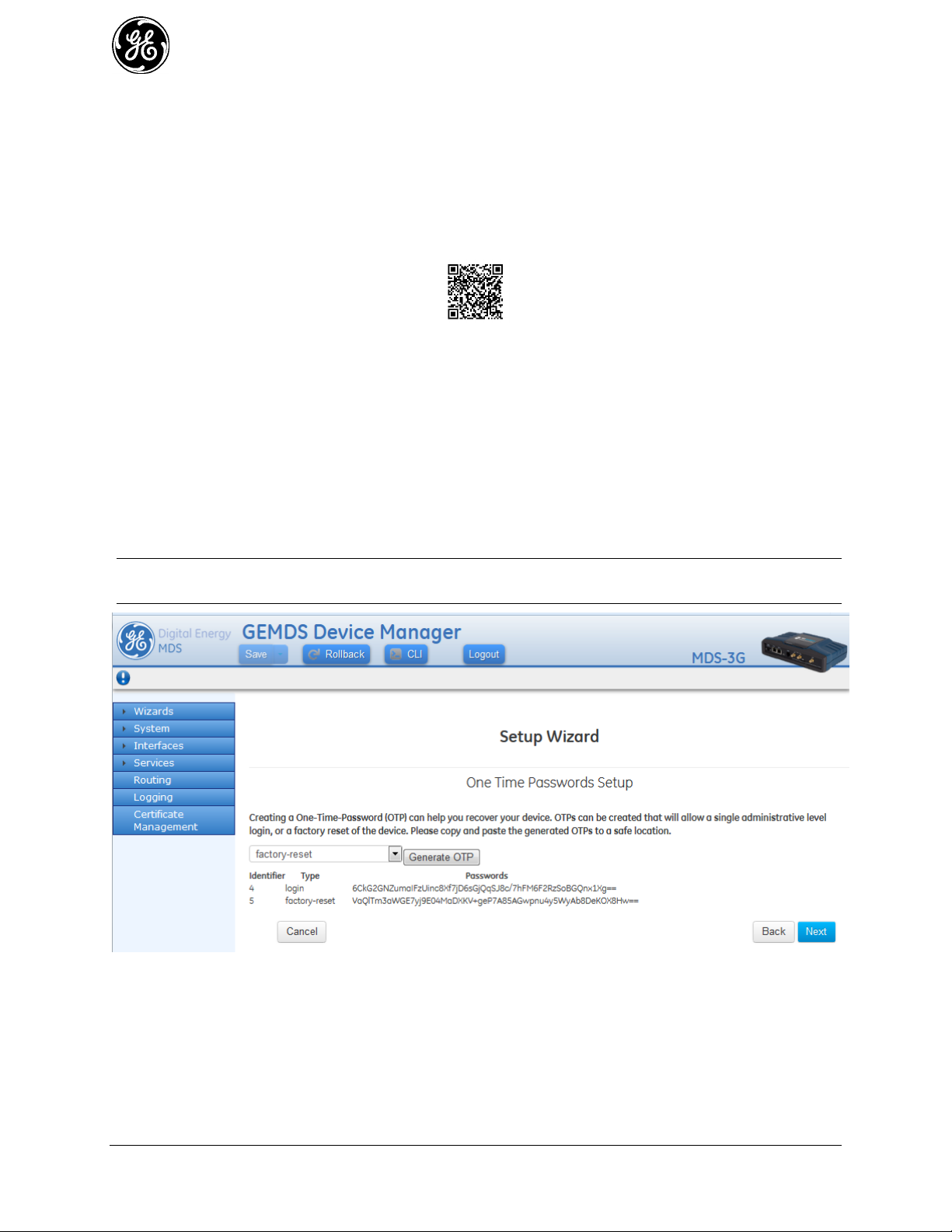
password is lost, there is no way to access the unit, except by using a one-time password (OTP) for
recovery. This must be established by the user beforehand. Without a one-time password, the unit will not
be accessible and the hardware will need to be returned to the factory to be re-imaged to defaults.
Technical Support will not be able to assist you if a password is lost, so creating a one-time password is
strongly encouraged. A device with a lost password
Refer to instructional video:
https://www.youtube.com/watch?v=qHiFg-QZP_Q&list=UUWEcxa9_FSdEqowzxNbNLsw&index=35
Associated QR Code:
One-Time Passwords: How They Work
One-time recovery passwords put control directly and exclusively in the user’s hands. They are similar to
spare keys for a lock. If you make a spare key and put it away safely, you can take it out to quickly gain
entry when your primary key is lost. If you don’t make a spare, you are always at risk of locking yourself
out.
A one-time recovery password is different from the one used to log into the unit on a routine basis. It is
only for use when the primary password is lost or forgotten. When a one-time password is used to log in,
that password is automatically revoked from the list of passwords created. You may create up to five onetime passwords at one time and more can be created if some get used. A password cannot be used again
for log in to the unit, hence the name “one-time” password.
NOTE One-time passwords are only displayed at the time of creation. The password must be saved and
archived at that time. There is no way to view this password again.
Figure 3-7. One-Time Password Add in Setup Wizard
Logging in With a One-Time Password
To use the one-time password for log-in, proceed as follows:
42 MDS Orbit MCR/ECR Technical Manual MDS 05-6632A01, Rev. G
Page 43

At the username prompt, enter the word “recovery”. 1.
At the password prompt, paste in the one-time-password saved earlier on your PC. Using a one-2.
time-password forces the unit to perform the function which was previously defined when the
password was created:
- factory-reset — The unit resets its entire configuration to factory defaults
- login — The unit allows logging in with admin privileges
Special case: If someone has disabled console access on the COM port, the login prompt will still be
present on that console, but only one-time passwords will be accepted. This is done to provide a way to
recover the unit in the case where the COM1 port has been disabled and the unit cannot be accessed via
TCP (for example; SSH).
Deleting a One-Time Password
As noted earlier, a one-time password is automatically revoked when it is used for log-in. A revoked
password may be replaced, but it must first be removed from the list so a new one can be generated. Any
of the five stored passwords may be removed on demand. As long as there is a free slot, an additional
password can be created, up to the maximum number of five. Logs are generated when the user creates,
deletes or logs in with a one-time-password.
Managing One-Time Passwords
One-Time passwords can be created as part of the Initial Setup Wizard, as shown in the example below.
To view currently configured One-Time Passwords, navigate to
Troubleshooting ---> Status / Recovery Information / Passwords
Figure 3-8. One-Time Password Display Screen
To edit or delete (revoke) a One-Time Password, navigate to:
Troubleshooting ---> Actions / One Time Passwords
MDS 05-6632A01, Rev. G MDS Orbit MCR/ECR Technical Manual 43
Page 44

Figure 3-9. One Time Passwords Management Screen
Up to 5 passwords may be added. They may also be deleted. Remember to replace a used password which
is automatically revoked. It must be deleted if there are no more password slots available.
Change Default Passwords 3.1.3
For security purposes it is highly advised to change the default passwords for all user roles. This is
accomplished on the “Change Password” Screen shown below located at:
User Authentication ---> Actions / Change Passwords
Figure 3-10. Change User Password Screen
This feature is also a part of the Initial Setup Wizard, as shown in the Figure below.
44 MDS Orbit MCR/ECR Technical Manual MDS 05-6632A01, Rev. G
Page 45
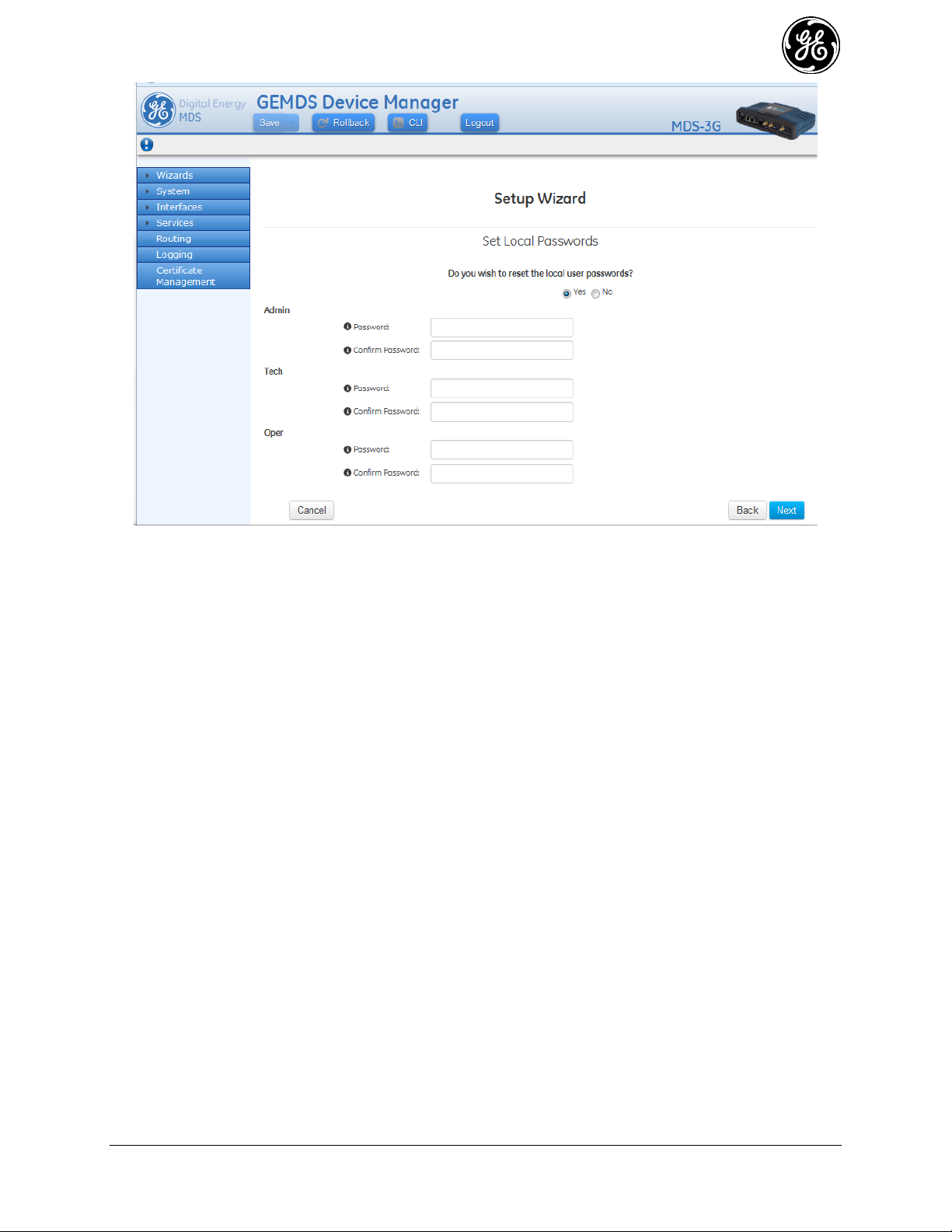
Figure 3-11. User Password Initial Setup Wizard Change Screen
The selected password(s) must follow the rules established on the “Password Options” screen located
under the Basic Config tab of the User Authentication section. These rules may be modified to conform
to the local security requirements.
Security Review 3.1.4
The Orbit MCR provides strong cyber security capabilities that may be customized to meet enterprise
security policy requirements. By default the Orbit MCR is configured with a light level of security. There
are many features and parameters that should be considered and adjusted according to the security policy.
Some of the areas to consider are:
User Authentication 1.
- Update factory default passwords.
- Secure login access into Orbit with local or RADIUS based user authentication.
Device Management 2.
- Secure access to Orbit for device management by enabling/disabling HTTP/HTTPS/SSH.
- It is recommended that HTTP be disabled.
- It is recommended that SNMPv1/v2c be disabled and SNMPv3 be enabled
Static Routing - Limit local broadcast and multicast traffic from being shared with specified 3.
interfaces.
Packet Filtering – Prevent ingress/egress of unwanted traffic by configuring firewall/NAT. 4.
Secure end-to-end network links using IPsec VPN with pre-shared-key or certificate based setup. 5.
Cellular Security – Utilize IPSec VPN to secure end-to-end cellular link over public cellular 6.
networks.
WiFi Security – Secure Wi-Fi link with pre-shared key or EAP-TLS/RADIUS using certificates. 7.
NX915 Security – Secure 900MHz link pre-shared key or EAP-TLS/RADIUS using certificates. 8.
MDS 05-6632A01, Rev. G MDS Orbit MCR/ECR Technical Manual 45
Page 46

LN Security – Secure Licensed Narrowband link pre-shared key or EAP-TLS/RADIUS using 9.
certificates.
Event Logging – Securely send event logs to central SYSLOG server by configuring SYSLOG over 10.
TLS.
PKI/Certificate Management – Generate/upload private keys/certifications for use in certificate 11.
based security setup.
Tamper Detection – Enable tamper detection to detect unauthorized device enclosure removal and 12.
physical movement from authorized install site.
3.2 Preconfigured Settings
The GE MDS factory configuration establishes typical settings based on the types of modules ordered.
The intent is to provide as much out-of-box functionality as possible. For example, in WiFi/Cell
configurations, the unit is configured as a WiFi hotspot.
The Orbit MCR is highly configurable to meet field requirements, but comes preconfigured as
follows:
- The COM and USB ports are enabled for local console operation.
- When applicable, interfaces are preconfigured as members of a bridge.
- A DHCP server is enabled for WiFi clients and the Ethernet LAN ports.
Units are configured with a set of pre-defined defaults set by the factory.
- Default Ethernet IP address 192.168.1.1
- Firewall/NAT/DNS proxy enabled
- DHCP server enabled
Other defaults
WiFi (hotspot):
- Set as Access Point (AP)
- SSID = GEMDS_<SERNUM> SERNUM refers to the unit’s serial number, printed on a
chassis sticker.
- The Ethernet ports are bridged with the WiFi AP.
- SSID broadcast enabled
- Security = WPA2-PSK, CCMP with passphrase: GEMDS_ORBIT
Cellular modem:
- 4G Cellular interface is enabled by default since network can enable connectivity on default
APN.
- 3G Cellular interface is disabled by default since it requires carrier specific APN to be
configured.
ISM Unlicensed 900 MHz radio (NX915):
- Radio Mode set to Remote
- Modem Mode 500kbps
- Power at 30 dBm
Licensed Narrowband radio (LN400/LN700/LN900):
46 MDS Orbit MCR/ECR Technical Manual MDS 05-6632A01, Rev. G
Page 47

- Radio Mode set to Remote
Step
Applicable Manual Section
Comment / Additional
Information
Establish connection to
the device (SSH/ Serial/
USB/ Web)
Initial Settings Overview
Specific Application Examples Using Device
Manager
Using the Command Line Interface (CLI)
With serial/USB/SSH
interfaces the "Command
Line Interface" (CLI) is
provided.
Create One-Time
Programmable
passwords for device
recovery in the event a
password is lost
One-Time “Recovery” Passwords
This is extremely important
for recovering a unit if a
admin password is lost.
Note - this is part of the
Initial Setup Wizard
Change the login
passwords/configure
users
Change Default Passwords
For security purposes it is
highly recommended that
password for all user type
be changed from their
defaults.
Note - this is part of the
Initial Setup Wizard
Review factory default
configuration
Preconfigured Settings
Disable DHCP if using
Static IP Addresses for
WiFi and Ethernet
port(s)
3.8.13 - DHCP Service
Set Date /Time or NTP
Server
3.7.1 - Date, Time and NTP
Note - this is part of the
Initial Setup Wizard
Set Geographic
Location (if desired)
3.7.2- Geographical-location
Note - this is part of the
Initial Setup Wizard
- Adaptive Modulation enabled
- FEC set to low gain
- Power at 40 dBm
These configuration settings allow a connection to a PC to the unit via WiFi or the LAN port and access
to the Internet via cellular, if equipped and supported by a suitable service plan.
3.3 Specific Application Examples Using Device Manager
The following examples illustrate the set of steps to configure the MCR for specific scenarios. The “Step”
column is the high level concept, The “Manual Section” provides a link to the manual section that can
explain in more detail and the “Comment...” column provides additional information or specific settings
pertinent to the example. More examples can be found in 05-6909A01 Orbit MCR Cookbook available
ton the GE MDS website.
Initial Setup Example
During the initial configuration of a device the following checklist in Table 3-2 should be consulted to
commission the unit for operation.
Table 3-2. Checklist for Initial Setup/Configuration
MDS 05-6632A01, Rev. G MDS Orbit MCR/ECR Technical Manual 47
Page 48

Step
Applicable Manual Section
Comment / Additional
Information
Configure WiFi (if
present)
3.5.3 - WiFi
Configure Cell interface
(if present)
3.5.2 - Cell
10.0 - APPENDIX E – Obtaining
Provisioned 4G/LTE Service (Verizon)
A guide to setting up
cellular service in the listed
Appendix
Configuring for 900MHz
operation (if present)
3.5.4 - Unlicensed 900 MHz ISM (NX915)
NX915 is the hardware
module that provides the
900 MHz operations. It is
factory configured based
on country codes for legal
operations.
Configuring for
Licensed Narrowband
operation (if present)
3.5.5 - Licensed Narrowband (LN)
LNxxx hardware modules
provide operation in
various narrowband global
frequencies. User
configuration is required to
match conditions of
license.
48 MDS Orbit MCR/ECR Technical Manual MDS 05-6632A01, Rev. G
Page 49

Application Example #1
Step
Applicable Manual
Section
Comment / Additional Information
Configure WiFi
3.5.3 - WiFi
Enable unit as Access Point
Set SSID mysid
Configure network
3.8.5 - Bridging
Add ETH1 and WiFi to the bridge
Set the Bridge IP
address
3.8.5 - Bridging
Set ipv4 address 192.168.1.21
Set prefix-length 24
Configure DHCP
Server
3.8.13 - DHCP Service
Set v4subnet 192.168.1.0/24
Set domain-name gemds
Set range-start 192.168.1.10
Set range-end 192.168.1.19
Set router 192.168.1.1
Set broadcast-address 192.168.1.255
In the figure below, the Orbit MCR is functioning as a WiFi Access Point to provide connectivity
between a set of laptops and a handheld device. The MCR is also acting as a DHCP server for the laptops
and handheld device.
Figure 3-12. Example 1: Unit Providing Laptop and Handheld Device Connectivity
By default the unit is configured in this basic configuration. Refer to Preconfigured Settings for accessing
the unit using the default setting for the Ethernet ports, WiFi and the bridge.
The following chart lists the required steps to configure the MCR for this specific scenario. Note that for
each step the linked manual section is provided as well as detailed information for use in recreating the
example.
MDS 05-6632A01, Rev. G MDS Orbit MCR/ECR Technical Manual 49
Page 50

Step
Applicable Manual Section
Comment / Additional
Information
Orbit MCR #1: Configure
WiFi as an Access Point
3.5.3 - WiFi
Enable Access Point mode
Create SSID of myssid
Orbit MCR #1: Configure to
bridge traffic from ETH1 and
WiFi
3.8.5 - Bridging
Add ETH1 and WiFi to the bridge
Orbit MCR #1: Set bridge IP
address
3.8.5 - Bridging
Set to 192.168.1.21
prefix-length 24
Orbit MCR #1: Enable
DHCP Server on bridge
3.8.13 - DHCP Service
Set v4subnet 192.168.1.0/24
Set domain-name: gemds
Set range-start: 192.168.1.10
Set range-end:192.168.1.19
Set router: 192.168.1.1
Set broadcast-address:
192.168.1.255
Orbit MCR #2: Configure
WiFi as an Station
connecting to Orbit MCR #1
3.5.3 - WiFi
Enable Station mode
Connect to AP SSID of myssid
Orbit MCR #2: Configure to
bridge traffic from ETH1 and
WiFi
3.8.5 - Bridging
Add ETH1 and WiFi to the bridge
Orbit MCR #2: Set bridge IP
address
3.8.5 - Bridging
Set to 192.168.1.22
prefix-length 24
Application Example #2
In the figure below, there are two Orbit MCR devices, one acting as a WiFi Access Point, the other as a
WiFi Station. Together, they provide a wireless bridge between the laptop and the SCADA device.
Figure 3-13. Example 2: Units Providing Wireless Bridge Between Laptop & SCADA Device
50 MDS Orbit MCR/ECR Technical Manual MDS 05-6632A01, Rev. G
Page 51

Application Example #3
Step
Applicable Manual Section
Comment / Additional Information
Orbit MCR #1: Configure
WiFi as an Access Point
3.5.3 - WiFi
Enable Access Point mode
Create SSID of myssid
Orbit MCR #1: Configure to
bridge traffic from ETH1 and
WiFi
3.8.5 - Bridging
Add ETH1 and WiFi to the bridge
Orbit MCR #1: Set bridge IP
address
3.8.5 - Bridging
Set to 192.168.1.21
prefix-length 24
Orbit MCR #1: Enable
DHCP Server on bridge
3.8.13 - DHCP Service
Set v4subnet 192.168.1.0/24
Set domain-name gemds
Set range-start 192.168.1.10
Set range-end 192.168.1.19
Set router 192.168.1.1
Set broadcast-address
192.168.1.255
Orbit MCR #2: Configure
WiFi as an Station
connecting to Orbit MCR #1
3.5.3 - WiFi
Enable Station mode
connect to AP SSID of myssid
Orbit MCR #2: Configure to
bridge traffic from ETH1 and
WiFi
3.8.5 - Bridging
Add ETH1 and WiFi to the bridge
Orbit MCR #2: Set bridge IP
address
3.8.5 - Bridging
Set to 192.168.1.22 prefix-length 24
Set up Terminal Server
COM1
3.8.14 - Terminal Service
Set mode udp
port 30000
remote addr: 192.168.1.11
port 30001
The figure below shows the Orbit MCR #2 device acting as a terminal server to provide connectivity to
the serial-based SCADA device via UDP.
Figure 3-14. Example 3: Unit Providing Connectivity to Serial-Based SCADA Device via UDP
NOTE The configuration for Orbit MCR #1 in Example 3: Unit Providing Connectivity to Serial-
Based SCADA Device via UDP is identical to the configuration shown in the previous example
(Example #2).
MDS 05-6632A01, Rev. G MDS Orbit MCR/ECR Technical Manual 51
Page 52

Step
Applicable Manual Section
Comment / Additional
Information
Configure ETH1 to be in
Bridge
3.8.5 - Bridging
Add ETH1 to the bridge.
Configure Bridge for an
IP address
3.8.5 - Bridging
Set address to 192.168.1.1
prefix length 24
Enable the firewall for
local address space
3.8.8 - Access Control List (Packet
Filtering / Firewall)
Enable firewall
Configure the incoming
out of network address
to accept only ICMP
3.8.8 - Access Control List (Packet
Filtering / Firewall)
Set Rule 1
protocol ICMP,
Action accept
Configure the incoming
out of network address
to drop all other traffic
(IN_UNTRUSTED)
3.8.8 - Access Control List (Packet
Filtering / Firewall)
Set Rule 10
protocol all,
Action drop
Configure the outgoing
destination to allow
local network
(OUT_UNTRUSTED)
3.8.8 - Access Control List (Packet
Filtering / Firewall)
Set Rule 1
src Address: LOCAL-NETS
Add Interface address; true
Action accept
Configure the outgoing
destination to drop
other network destined
packets
(OUT_UNTRUSTED)
3.8.8 - Access Control List (Packet
Filtering / Firewall)
Set Rule 10
protocol all
Action drop
Enable Firewall NAT to
masquerade
3.8.8 - Access Control List (Packet
Filtering / Firewall)
rule-set: MASQ
Enable Firewall NAT
rule
3.8.9 - Source NAT (Masquerading)
Set Rule 1
source-nat : interface
Enable Cell interface
3.5.2 - Cell
Apply Firewall
IN_UNTRUSTED and
OUT_UNTRUSTED
filters to Cell interface
3.8.8 - Access Control List (Packet
Filtering / Firewall)
Set Cell input filter to
IN_UNTRUSTED
Set Cell output filer to
OUT_UNTRUSTED
Set NAT on Cell
interface to
masquerade
3.8.9 - Source NAT (Masquerading)
Set cell NAT source to MASQ
Application Example #4
In the figure below, an Orbit MCR provides internet access for a laptop that is accessing a public web
page.
Figure 3-15. Example 4: Unit Providing Internet Access for Laptop
SIM Type: In this scenario, the MCR-4G has a SIM card installed that simply provides Internet access.
52 MDS Orbit MCR/ECR Technical Manual MDS 05-6632A01, Rev. G
Page 53

3.4 Using the Command Line Interface (CLI)
ENTER
ENTER
Differences between Serial and SSH 3.4.1
Serial and SSH both present identical management capabilities, but the method of access is different for
each. Serial involves an RS-232 serial connection from a PC to the unit’s COM port. SSH uses an
Ethernet PC connection to the unit’s ETH port. Maximum recommended cable length for a serial
connection is 50 feet (15 meters). SSH can be connected to the unit from any network point that has
connectivity with the PC, including remotely over the Internet, or using other networks.
The focus of these instructions is on Serial access, but SSH may also be used by following these
additional points, which replace Steps 1-3 below:
Connect to the unit with a PC that is in the same IP network as the MCR. Launch an SSH client
program and connect to the unit using its programmed IP address.
The default IP address for the unit is 192.168.1.1. If you do not know the current IP address of the
unit, follow the serial configuration instructions below, where you can determine the address and
continue configuration, or check with your network administrator.
Establishing Communication—Serial Interface 3.4.2
Follow these steps to configure the unit for its first use with serial console interface:
Connect a PC to the unit’s COM port as shown in Figure 3-16. Maximum recommended cable 1.
length is 50 ft/15 m.
NOTE Not all PCs include a serial port. If one is not available, the Orbit MCR’s USB port can be used
to access the device management console by using a Mini-USB cable between the device and a
PC. The PC needs to install the device driver.
NOTE If the COM port has been configured for terminal server operation, pressing +++ switches it to
console (management) mode. Serial console mode is required for the following steps.
Launch a terminal communications program, such as HyperTerminal, with the following
communication parameters: 115200 bps (default speed), 8 bits, no parity, one stop bit (8N1) and
flow control disabled. Incorrect parameter settings are a frequent cause of connection difficulties.
Double check to be sure they are correct.
An adapter may be used to convert the unit’s RJ-45 serial jack to a DB-9F type (GE MDS part no.
73-2434A25). If no serial port exist on the PC, a Mini-USB cable may be connected between the
MCR’s USB device port and the PC.
Figure 3-16. PC Connection for Programming/Management
Press the key to receive the Login: prompt. This indicates that the unit is ready to receive 2.
commands.
At the Login: prompt, enter admin (lower case) and press . 3.
MDS 05-6632A01, Rev. G MDS Orbit MCR/ECR Technical Manual 53
Page 54

ENTER
If no password has been previously set, enter the default password (admin) and press ; 4.
otherwise, enter the saved password at the Password: prompt. (Before placing the unit in final
service, it is recommended that the default password be changed to ensure that only authorized
users have access.)
After successful login, the command prompt appears where you may configure and manage a 5.
number of unit settings.
Using the CLI 3.4.3
This section describes how to use the CLI by using an example: changing the name of the unit.
Step 1: Login to the device using the serial console and use the default username admin and the default
password admin.
(none) login: admin
Password:
Welcome to the CLI
admin connected from 127.0.0.1 using console on (none)
Step 2: Instruct the device to enter configuration mode by typing configure and pressing the enter key:
> configure
Entering configuration mode private
Step 3: Change the device name by typing in the following, followed by enter: set system name
Device539
% set system name Device539
Step 4: Verify the change looks correct by reading the data back, using the following, followed by the
enter key: show system name
% show system name
name Device539;
Step 5: Commit the change by typing in the following, followed by the enter key: commit
% commit
Commit complete.
Step 6: Exit the configuration mode by typing the following, followed by the enter key: exit
% exit
Step 7: Exit the login session by typing the following, followed by the enter key: exit
> exit
Device539 login:
Tab Completion Feature
Tab-completion is a powerful feature that presents CLI users with assistance while typing. Depending on
the text that was already entered, tab-completion will display different possible completions. When the
tab key is pressed and no text has been entered, the CLI shows all possible commands that can be typed.
Creating a One-Time Password
To create a one-time recovery password, proceed as follows:
Upon successful log-in, enter the following command:
> request system recovery one-time-passwords create function <selected function>
54 MDS Orbit MCR/ECR Technical Manual MDS 05-6632A01, Rev. G
Page 55

NOTE A one-time password is automatically generated and displayed on the screen. Copy this
Table 3-3. CLI Quick Reference Table
If you wish to...
Enter this CLI command:
Create a one-time password
> request system recovery one-time-password create function
<user function>
View all network interface
status and statistics
> show interfaces-state interface
Create a bridge
% set interfaces interface Bridge type bridge
Add the ETH1 interface to a
bridge
% set interfaces interface Bridge bridge-settings members port
ETH1
Remove the ETH1 interface
from a bridge
% delete interfaces interface Bridge bridge-settings members port
ETH1
Set WiFi AP SSID
% set interfaces interface Wi-Fi wifi-config mode access-point apconfig ap myssid
Enable WiFi WPA2-Personal
security
% set interfaces interface Wi-Fi wifi-config mode access-point apconfig ap myssid privacy-mode wpa2-personal psk-config psk
mypassphrase encryption ccmp
Enable WiFi SSID
Broadcasting
% set interfaces interface Wi-Fi wifi-config ap-config ap myssid
broadcast-ssid true
View Cell Settings
> show configuration interfaces interface Cell cell-config
Monitor Cell Status
> show interfaces-state interface Cell cell-status | repeat 5
View NxRadio Settings
> show configuration interfaces interface NxRadio nx-config
Monitor NxRadio Status
> show interfaces-state interface NxRadio nx-status | repeat 5
View WiFi Settings
> show configuration interfaces interface Wi-Fi wifi-config
password and save it in the desired location on your PC. There is no way to ever view it again
from the command line console, so be sure it is properly saved.
To create additional one-time passwords (up to a total of five), repeat the step above.
Deleting a One-Time Password
To remove an existing password from the list, proceed as follows:
Enter the command request system recovery one-time-passwords delete identifier X, where X is a number
from the currently available one-time passwords. This identifier is not reused. If all five passwords have
been created, then ID 1 can be deleted and the next created password will be at ID 6.
The current list of passwords may be viewed by issuing the command show system recovery one-timepasswords. The following is an example output from that command. On the unit shown, only two
passwords have been stored. Password 1 or 2 can be deleted from this list.
IDENTIFIER FUNCTION STATUS DATE CREATED DATE REVOKED USER
-----------------------------------------------------------------------------------------------------------------------------------------------1 login usable 2012-06-19T00:27:24+00:00
2 login usable 2012-06-19T00:27:25+00:00
CLI Quick Reference Table 3.4.4
Table 3-3 provides a summary listing of commonly needed tasks and the appropriate commands to enter.
The table can be used as a quick reference before consulting the more detailed information, which follows
in this section. Each CLI command is preceded by the symbol > for operational command, or % for a
configuration command.
MDS 05-6632A01, Rev. G MDS Orbit MCR/ECR Technical Manual 55
Page 56

Table 3-3. CLI Quick Reference Table
If you wish to...
Enter this CLI command:
Monitor WiFi Status
> show interfaces-state interface Wi-Fi wifi-status | repeat 5
View the routing table
> show routing
View the event log
> show table logging event-log
Set the admin user’s
password
> request system authentication change-password user admin
password admin1234
Set the device name
% set system name “Mydevice”
Set the baud rate on COM1
% set services serial ports COM1 baud-rate b19200
Download a firmware
package from TFTP server at
192.168.1.10
> request system firmware reprogram-inactive-image filename
mcr-bkrc-4_0_0.mpk manual-file-server { tftp { address
192.168.1.10 } }
Monitor firmware
reprogramming status
> show system firmware reprogram-status
Export configuration file to a
TFTP server at 192.168.1.10
> request system configuration-files export filename
myConfig.xml manual-file-server { tftp { address 192.168.1.10 } }
Reboot device to firmware
inactive image
> request system power restart inactive
56 MDS Orbit MCR/ECR Technical Manual MDS 05-6632A01, Rev. G
Page 57

Specific Examples Using CLI 3.4.5
Example #1
In Figure 3-17, the Orbit MCR is functioning as a WiFi Access Point to provide connectivity between a
set of laptops and a handheld device. The MCR is also acting as a DHCP server for the laptops and
handheld device.
Figure 3-17. Example 1: Unit Providing Laptop and Handheld Device Connectivity
The following commands will configure the MCR for this scenario.
% set interfaces interface Wi-Fi type wifi
% set interfaces interface Wi-Fi wifi-config mode access-point ap-config ap myssid enabled
true
% set interfaces interface Bridge type bridge
% set interfaces interface Bridge bridge-settings members port ETH1
% set interfaces interface Bridge bridge-settings members wifi-ap myssid
% set interfaces interface Bridge ipv4 address 192.168.1.21 prefix-length 24
% set services dhcp enabled true v4subnet 192.168.1.0/24 domain-name gemds range-start
192.168.1.10 range-end 192.168.1.19 router 192.168.1.1 broadcast-address 192.168.1.255
MDS 05-6632A01, Rev. G MDS Orbit MCR/ECR Technical Manual 57
Page 58
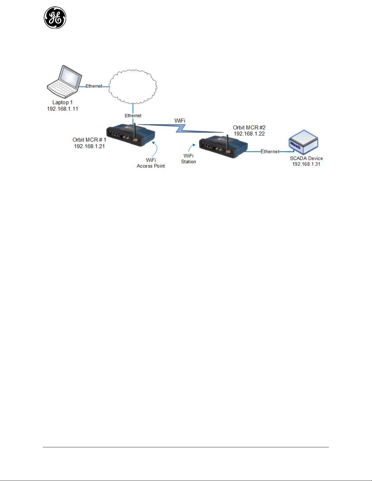
Example #2
In Figure 3-18, there are two Orbit MCR devices, one acting as a WiFi Access Point, the other as a WiFi
Station. Together, the units are providing a wireless bridge between the laptop and the SCADA device.
Figure 3-18. Example 2: Units Providing Wireless Bridge Between Laptop & SCADA Device
The following commands will configure the Orbit MCR #1 for this scenario.
% set interfaces interface Wi-Fi type wifi
% set interfaces interface Wi-Fi wifi-config mode access-point ap-config ap myssid enabled
true
% set interfaces interface Bridge bridge-settings members wifi-ap myssid
% set interfaces interface Bridge ipv4 address 192.168.1.21 prefix-length 24
% set services dhcp enabled true v4subnet 192.168.1.0/24 domain-name gemds range-start
192.168.1.10 range-end 192.168.1.19 router 192.168.1.1 broadcast-address 192.168.1.255
The following commands will configure the Orbit MCR #2 for this scenario.
% set interfaces interface Wi-Fi type wifi
% set interfaces interface Wi-Fi wifi-config mode access-point ap-config ap myssid enabled
true
% set interfaces interface Bridge type bridge
% set interfaces interface Bridge bridge-settings members port ETH1
% set interfaces interface Bridge bridge-settings members wifi-station interface Wi-Fi
% set interfaces interface Bridge ipv4 address 192.168.1.22 prefix-length 24
58 MDS Orbit MCR/ECR Technical Manual MDS 05-6632A01, Rev. G
Page 59

Example #3
Figure 3-19 shows the Orbit MCR #2 device acting as a terminal server to provide connectivity to the
serial-based SCADA device via UDP.
NOTE The configuration for Orbit MCR #1 in Figure 3-19. Example 3: Unit Providing Connectivity to
Serial-Based SCADA Device via UD is identical to the configuration shown in the previous
example (Example #2).
Figure 3-19. Example 3: Unit Providing Connectivity to Serial-Based SCADA Device via UDP
The following commands will configure the Orbit MCR #2 for this scenario.
% set interfaces interface Wi-Fi type wifi
% set interfaces interface Wi-Fi wifi-config mode access-point ap-config ap myssid enabled
true
% set interfaces interface Bridge type bridge
% set interfaces interface Bridge bridge-settings members port ETH1
% set interfaces interface Bridge bridge-settings members wifi-station interface Wi-Fi
% set interfaces interface Bridge ipv4 address 192.168.1.22 prefix-length 24
% set services serial terminal-server server COM1 mode udp port 30000 remote address
192.168.1.11 port 30001
MDS 05-6632A01, Rev. G MDS Orbit MCR/ECR Technical Manual 59
Page 60
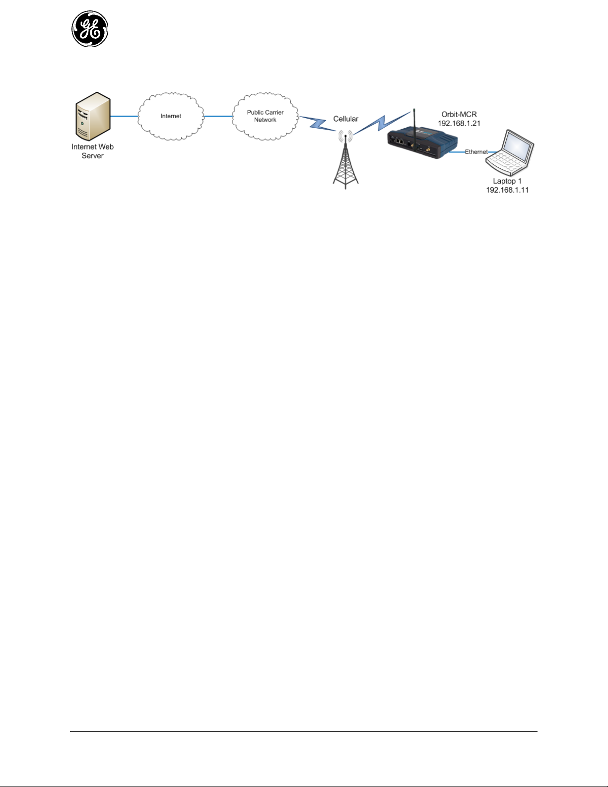
Example #4
In Figure 3-20, an Orbit MCR provides internet access for a laptop that is accessing a public web page.
Figure 3-20. Example 4: Unit Providing Internet Access for Laptop
SIM Type: In this scenario, the MCR-4G has a SIM card installed that simply provides Internet access.
The following commands will configure the MCR-4G for this scenario.
% set interfaces interface Bridge type bridge
% set interfaces interface Bridge bridge-settings members port ETH1
% set interfaces interface Bridge ipv4 address 192.168.1.1 prefix-length 24
% set services firewall enabled true
% set services firewall address-set LOCAL-NETS addresses [192.168.1.0/24]
% set services firewall filter IN_UNTRUSTED rule 1 match protocol icmp
% set services firewall filter IN_UNTRUSTED rule 1 actions action accept
% set services firewall filter IN_UNTRUSTED rule 10 match protocol all
% set services firewall filter IN_UNTRUSTED rule 10 actions action drop
% set services firewall filter OUT_UNTRUSTED rule 1 match src-address address-set
LOCAL-NETS
% set services firewall filter OUT_UNTRUSTED rule 1 match src-address add-interface-
address true
% set services firewall filter OUT_UNTRUSTED rule 1 actions action accept
% set services firewall filter OUT_UNTRUSTED rule 10 match protocol all
% set services firewall filter OUT_UNTRUSTED rule 10 actions action drop
% set services firewall nat source rule-set MASQ
% set services firewall nat source rule-set MASQ rule 1 source-nat interface
% set interfaces interface Cell type cell enabled true
% set interfaces interface Cell filter input IN_UNTRUSTED
% set interfaces interface Cell filter output OUT_UNTRUSTED
% set interfaces interface Cell nat source MASQ
60 MDS Orbit MCR/ECR Technical Manual MDS 05-6632A01, Rev. G
Page 61
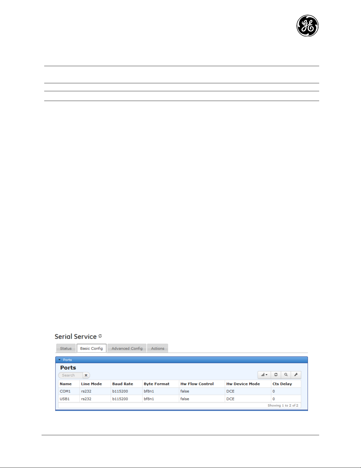
The following sections describe key operational features of the MCR unit and list configuration options
for them. Each major heading begins at the top of a new page. For this reason, large areas of white space
exist at the end of some sections. This is done to provide a clear delineation between major sections.
NOTE The LAN port should be assigned IP addresses only if it is a routed interface (that is, not in a
bridge).
NOTE The commands that follow in this section vary depending on the Orbit MCR options ordered.
3.5 Interface Configuration
Serial Interface 3.5.1
Understanding
Orbit supports COM ports (RJ45) that can be used for either console access (the CLI) or payload data.
Depending on ordered options, the unit may have multiple COM ports. COM ports serves as the primary
interface for connecting the unit to an external DTE serial device supporting RS-232 or RS-485. By
default, a COM ports are enabled for local console control, using 115200 bps with 8N1 format.
A mini-USB-to-USB cable may also be used to connect to a Computer in case no physical serial device
exists. If a mini-USB connection is used, the computer must contain the appropriate device driver. A
driver for serial operation can be found on GE MDS website.
Orbit considers the COM ports and the USB as members of a broader interface category called “serial
ports”. In Orbit, serial ports include any user addressable interfaces that pass serial bytes. Depending on
configuration, serial ports may also include virtual ports that provide access to the serial data stream of
internal Orbit interfaces. This is useful, for example, to allow the Orbit to access the over-the-air serial
data stream of legacy licensed narrowband MDS radios.
Serial ports in Orbit can be used in one of three ways:
Console / Command Line access – the CLI for administering the unit 1.
Terminal Server – conversion between serial and IP 2.
Serial Pass-Through – direct connection between serial interfaces 3.
Configuring
The screens below shows examples for how to configure the COM1 and USB serial ports:
Navigate to: Serial ---> Basic Config / Ports
Click on COM1 to get:
MDS 05-6632A01, Rev. G MDS Orbit MCR/ECR Technical Manual 61
Page 62

Figure 3-21. COM1 Configuration Screen
Line Mode - Selection of the operation line mode of the serial port. Choices are:
- RS232 (DEFAULT)
- RS485 - 2 Wire
- RS485 - 4 Wire
Baud Rate - The serial port baud rate in bps. Choices are 1200, 2400, 4800, 9600, 19200, 38400,
57600, 115200 (DEFAULT), 230400.
Byte Format - The data byte format in bits, parity and stop bits: Choices are:
- 7N1 - 7 char bits, no parity, 1 stop bit
- 7E1 - 7 char bits, even parity, 1 stop bit
- 7O1 - 7 char bits, odd parity, 1 stop bit
- 7N2 - 7 char bits, no parity, 2 stop bits
- 7E2 - 7 char bits, even parity, 2 stop bits
- 7O2 - 7 char bits, odd parity, 2 stop bits
- 8N1 - 8 char bits, no parity, 1 stop bit (DEFAULT)
- 8E1 - 8 char bits, even parity, 1 stop bit
- 8O1 - 8 char bits, odd parity, 1 stop bit
- 8N2 - 8 char bits, no parity, 2 stop bits
- 8E2 - 8 char bits, even parity, 2 stop bits
- 8O2 - 8 char bits, odd parity, 2 stop bits
Hw Flow Control - Hardware flow control enable/disable (DEFAULT) using RTS/CTS lines
Vmin - Receive Buffer Size - The minimum number of data bytes that will be buffered by the serial
port before handling of the data to be processed by the terminal server. (255 = DEFAULT).
Vtime - Receive Inter-Byte Timeout - The amount of time between bytes of data on the serial port in
milliseconds, that indicate the end of a serial message ready to be processed by the terminal server.
(100 = DEFAULT)
62 MDS Orbit MCR/ECR Technical Manual MDS 05-6632A01, Rev. G
Page 63
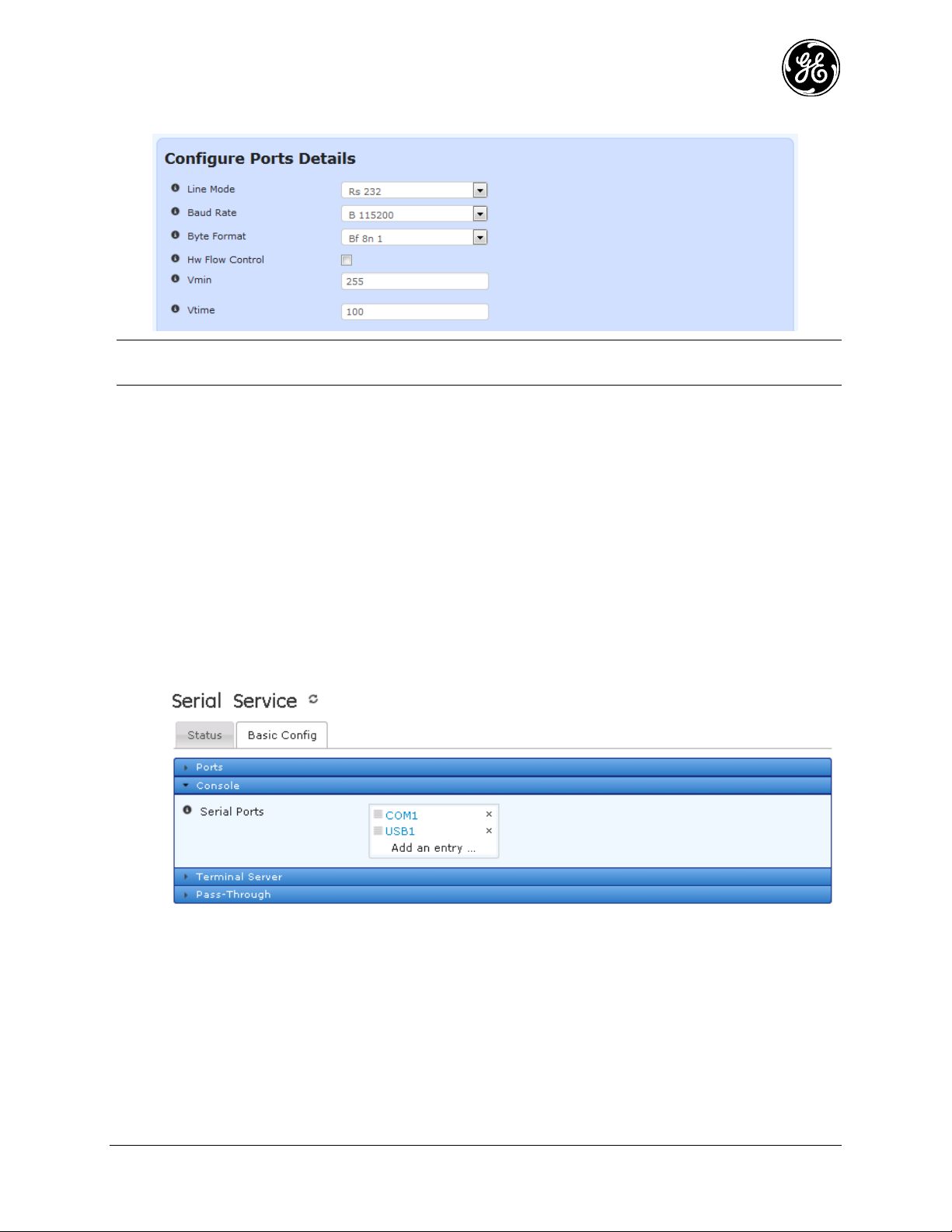
Click on the USB1 to get:
NOTE For serial ports other than physical COM ports, the only useful attributes are Vmin and Vtime.
Other settings like line mode, baud rate, and flow control are ignored.
Vmin - Receive Buffer Size - The minimum number of data bytes that will be buffered by the serial
port before handling of the data to be processed by the terminal server. (255 = DEFAULT).
Vtime - Receive Inter-Byte Timeout - The amount of time between bytes of data on the serial port in
milliseconds that indicates the end of a serial message ready to be processed by the terminal server.
(100 = DEFAULT)
Console Settings
Any physical serial port can be set up as a console port by adding the port under the Console tab.
Navigate to: Serial ---> Basic Config / Console
From the CLI, this sequence shows how to add console access to the COM1 and COM2 serial ports and
set the COM2 baud rate to 19200 bps:
% set services serial console serial-ports [COM1 COM2]
% set services serial ports COM2 baud-rate b19200
% commit
MDS 05-6632A01, Rev. G MDS Orbit MCR/ECR Technical Manual 63
Page 64

Terminal Server Settings
When configuring a serial port that will be used as a terminal server the VMIN and VTIME settings need
additional explanation. As described above VMIN is a number describing bytes that are received from the
interface, while VTIME is a delay value in milliseconds. These parameters act together to control serial
data collection and transmission as described below:
VMIN == 0; VTIME == 0: The terminal server will continuously read to see if a byte if data is
available and process each byte.
NOTE While this is a valid mode in most cases this causes a high processing load on the device that
may impact performance of other operations of the device.
VMIN > 0; VTIME == 0: The terminal server waits to process data until at least VMIN bytes
of serial data are received.
VMIN == 0; VTIME > 0: If serial data is received, the terminal server will continuously read
the number of bytes available until VTIME has elapsed then process the data.
VMIN > 0; VTIME > 0: Once an initial byte of input becomes available the terminal server
waits until the MIN bytes have been read, or when the inter-byte timeout expires. The timer is
restarted after each further byte is received and because the timer is started only after the initial
byte is received, at least one byte will be read.
For more information on Terminal Server configuration see 3.8.14.
Pass-Through Settings
Orbit offers Serial Pass-Through operation as a low-overhead means to transport serial data. Unlike
Terminal Server operation, there is no need to convert the serial data to IP.
A Pass-Through Instance defines the connection between the two serial ports.
Navigate to: Serial ---> Basic Config / Pass-Through
64 MDS Orbit MCR/ECR Technical Manual MDS 05-6632A01, Rev. G
Page 65

The example below defines a Pass-Through Instance to connect COM1 to an Orbit LN operating in
transparent-serial mode (backward compatible to x710). First the instance is named as shown:
Next the connection is specified between the ports, labeled Port 1 and Port 2.
Clicking the “…” button provides the serial port choices. In this example, COM1 is the physical serial
port; LnRadio-serial is the virtual serial port created automatically when an Orbit LN interface is
configured for “transparent-serial” operation.
MDS 05-6632A01, Rev. G MDS Orbit MCR/ECR Technical Manual 65
Page 66

The last image below shows the final configuration prior to selecting the “Finish” button.
Note that the“Display Banner” check-box at the bottom applies to ports that also function as Console
ports. It indicates whether or not an informational message is displayed on startup describing that the port
is going into data mode and not available for console use.
Serial Hardware Flow Control
Hardware Flow Control: When operating in CTSKEY mode, all serial ports in the data path are required
to be set to the same baud rate, and that VMIN and VTIME remain at the defaults for serial data packets
less than or equal to 255 bytes. For serial packets over 255 bytes it is recommended that a cts-delay time
of at least 90ms be used to account for the VTIME delay of the over-the-air sending unit.
Hardware Flow Control Modes:
DCE 1.
CTS follows RTS after a programmable CTS delay.
If the unit’s input buffer approaches a full condition it can deassert CTS regardless of state of
RTS.
CTSKEY 2.
Based on legacy MDS devices including TransNET and SD, the device will act similar to a
DTE but will provide signaling on the CTS line instead of the RTS line.
When the first character of a transmission is ready to be sent to the serial port, the unit shall
assert CTS and delay for CTS delay time expiration before outputting the first character.
After the last character of a transmission is output from the serial port, the unit shall keep CTS
asserted until the expiration of CTS hold time.
CTSKEYPLUS 3.
The unit shall support flow control (Throttling) on the RTS pin. The device is expected to be
wired via null modem to an external DCE device. The CTS line of the external DCE device
drives the RTS line of the unit.
Outlined Configuration: Orbit MCR: Hardware Flow Control
Configure Serial Port under test for Hardware Flow Control 1.
Configure Hw Flow Control to true
Configure Hw Device Mode: DCE, CTSKEY, CTSKEYPLUS
Configure any remaining parameters, Cts Delay, Cts Hold, VMIN, VTIME
66 MDS Orbit MCR/ECR Technical Manual MDS 05-6632A01, Rev. G
Page 67

Save/Commit Configuration 2.
Step by step Web based Walkthrough:
On the left hand side of the Web GUI, click Services. 1.
Click Serial from the Services drop down. 2.
Click the Serial Port Name on the Basic Config tab to configure Hardware Flow Control. 3.
NOTE Cts Hold -The CTS hold parameter is applicable only when h/w device mode = CTSKEY or
CTSKEYPLUS. This parameters specifies the time (in milliseconds) to hold CTS up after data
is transmitted.
To enable Hardware Flow Control, click the Hw Flow Control checkbox. 1.
Adjust the new parameters to fit the system, Hw Device Mode, Cts Delay, Cts Hold. 2.
This is also where VMIN and VTIME can be adjusted. 3.
Save the Configuration. 4.
CLI Configuration Commands
Change ITALICS to fit the system
Configure the following as an example:
% set services serial ports COM1 hw-flow-control true hw-device-mode CTSKEY cts-delay 90
cts-hold 40
% commit
Monitoring
From the Web UI, the Serial Ports screen shows the settings:
Navigate to: Serial ---> Basic Config / Ports
MDS 05-6632A01, Rev. G MDS Orbit MCR/ECR Technical Manual 67
Page 68

NOTE Vmin and Vtime are not displayed by default. To modify the view, click the button and
add them to the view.
From the CLI in operational mode, follow the example below to view the state and statistics:
> show configuration services serial | details
ports COM1 {
line-mode rs232;
baud-rate b115200;
byte-format bf8n1;
hw-flow-control false;
vmin 255;
vtime 1;
capability rs485-2-wire,rs485-4-wire;
}
ports COM2 {
line-mode rs232;
baud-rate b19200;
byte-format bf8n1;
hw-flow-control false;
vmin 255;
vtime 1;
capability "";
}
console {
serial-ports [ COM1 COM2 ];
}
Cell 3.5.2
Understanding
Orbit MCR product family is available with following cellular modem options:
Verizon Wireless 4G LTE modem
3G GSM/UMTS/HSPA+ modem
4G LTE GSM (EMEA/APAC)
4G LTE GSM (North America)
68 MDS Orbit MCR/ECR Technical Manual MDS 05-6632A01, Rev. G
Page 69

NOTE GE MDS is continually certifying the product for different countries and carriers, please contact
Application
Location
Frequency
Range
Gain
Antenna Description
GE MDS Part
Number
3G/4G
Cellular
Indoor
698-2700MHz
CELL BANDS
2 dBi
Direct Connect, - SMA Paddle
antenna
97-2485A04
3G/4G
Cellular
Outdoor
698-2700MHz
CELL BANDS
4.5 dBi
External Mount, Omni Ant. with
N-Female connector - no cable
Note: requires a metal Ground
Plane
97-2485A05
3G/4G
Cellular
Outdoor
698-2700MHz
CELL BANDS
1 dBi
External Mount, Dipole Omni with
N-Female connector - no cable
97-2485A06
LED - NIC1
State
Description
Cell Interface
Off
Solid green
No cellular connection
Cell connection
GE MDS sales or technical support to inquire about the current certification status for particular
country/carrier.
Orbit MCR supports routing of TCP/UDP/IP data from the Cellular WAN network interface to any of the
other network interfaces (including WiFi or LAN) using the IPsec VPN or network address and port
translation (NAPT) feature and to the COM1 (or COM2) serial port using the terminal server service. The
configuration of these use cases is specified in the respective sections on VPN, Firewall and NAT and
Terminal Service.
The cellular modem inside the unit supports main (primary) and secondary antenna (for receive diversity).
The primary antenna must be installed for the cell modem to register with the cellular network. It is
strongly recommended that a secondary antenna be installed for achieving a robust cellular link. There
should be no physical obstructions around the antennas. The main and diversity antennas must have at
least 27 dB of isolation from each other to ensure optimal operation of the cellular modem. For Antenna
Installation assistance, see “Antenna Planning and Installation” on Page 31 or contact your local GE MDS
representative. See the below table for approved Antenna Types.
Table 3-4. Approved Cell Antenna Types
Table 3-5 describes the Orbit MCR’s LED behavior when using the cellular interface.
Table 3-5. Cell Interface LED Descriptions
SIM Port(s) - These ports accept a mini SIM card (2FF type) for cell operation. The unit’s cellular
interface will not function without a valid SIM card installed. Users are responsible for obtaining a
provisioned SIM card for the appropriate service plan from their cellular provider. Information on
determining the cell module’s IMSI/IMEI (typically required for provisioning) is provided on Page 79 of
this manual.
CAUTION: Do not insert the SIM card when the unit is powered on.
Card Insertion: The SIM card only inserts one way; do not force it. It should be inserted with the printed
label facing up and the cut-off corner on the left side (see figure below). A small instrument, such as a
flathead screwdriver, may be helpful to gently push the SIM all the way in until it locks.
MDS 05-6632A01, Rev. G MDS Orbit MCR/ECR Technical Manual 69
Page 70

Figure 3-22. Steps for Inserting the SIM Card
NOTE The insertion example above shows the default SIM slot (Slot A). Units equipped with multiple
SIM ports will label the upper slot SIM B and the lower slot SIM A.
NOTE Dual SIM functionality is a selective order-entry feature. Default units are shipped with only
SIM-A enabled; SIM-B is not supported.
Configuring
A Connection Profile must be configured for the unit to establish a data connection with the cellular
network. A connection profile allows the user to configure various parameters related to the cellular
connection. One or more connection profiles can be configured on the unit. The order of the connection
profiles can be chosen by the user. The unit will use the first connection profile to establish connection
with the cellular network. If connection profile switching (described later) is enabled, then the unit will
switch to second profile in the list if it is unable to establish a connection using the first profile after a
configurable, specified timeout.
An Orbit MCR equipped with a Verizon 4G LTE modem is shipped out of the factory with the cellular
interface enabled and a connection profile (named PROFILE-1) configured to connect with Verizon's
Internet Packet Data Network (PDN).
An Orbit MCR equipped with a 3G GSM modem is shipped out of the factory with the cellular interface
disabled. The user will need to create a connection profile with the cellular network specific parameters
prior to enabling the interface to allow unit to connect to the network.
In the UI, start on the following page: Interfaces / Cell ---> Basic Config / Cellular
Figure 3-23. Connection and Connection Profile Switching UI Screen
70 MDS Orbit MCR/ECR Technical Manual MDS 05-6632A01, Rev. G
Page 71

The cellular configuration is configured by creating a “Connection Profile” to describe the connection and
consists of four major groups of information:
Network Configuration - contains various parameters related to how the modem registers with the
cellular network.
Bearer Configuration - parameters related to data connection with the cellular network.
Keep Alive - Keep alive configuration for sending ICMP Echo messages to a remote host/server
periodically to keep the connection alive
Service Recovery - Service recovery configuration
If multiple cellular providers are supported, the “Connection Profile Switching” choices may need to be
configured.
The following is an example UI screen to create a connection profile named ORBIT1 by clicking on the
ADD button and naming the profile as such.
Figure 3-24. Example Connection Profile
Each Connection Profile has grouped information that contains specific information to be selected. The
choices are described below:
Network Configuration - contains various parameters related to how the modem registers with
the cellular network.
MDS 05-6632A01, Rev. G MDS Orbit MCR/ECR Technical Manual 71
Page 72

Technology-selection - The user can configure the modem to automatically select the network
technology to connect to (automatic) or force it to register only on:
- Automatic (DEFAULT)
- 2G GSM (geran),
- 3G UMTS (utran),
- 4G LTE (e-utran),
- 2G CDMA(cdma-1xrtt)
- 3G CDMA EV-DO (cdma-evdo).
Service Domain - Network Service Domain - choices are:
- Circuit Switched (CS) and Packet Switched (PS)
- Packet Switched (PS) Only
If cellular network does not support CS then configure as PS Only. Consult your service provider for this
information. Typically, this field is left as default.
Bearer Configuration - parameters related to data connection with the cellular network.
Apn - Once the unit has registered to the cellular network, it sets up the IP data connection
with a specific Packet Data Network (PDN) identified by the Access Point Name (APN). APN
is a string identifier. An Orbit MCR equipped with a Verizon 4G LTE modem comes
preconfigured with an APN of vzwinternet. Hence, it attempts to set up a data connection
towards Verizon's internet PDN that provides internet connectivity. For this data connection to
succeed, a SIM card that has been provisioned for internet access needs to be obtained from
the Verizon Wireless and installed in the unit. See “ APPENDIX E – Obtaining Provisioned
4G/LTE Service (Verizon)” on Page 429. If a private network (PN) account has been set up
with Verizon wireless, a SIM card will be issued from that account. When the modem is
powered up with such a SIM, the default APN on the modem is automatically updated to the
one that identifies the user’s private network. This procedure is called OTA APN update. This
procedure might not always succeed and hence, may require the user to manually update the
APN on the MCR.
The following example shows how to update the APN to, MYAPN.GW6.VZWENTP, manually,
via the CLI:
% set interfaces interface Cell cell-config connection-profile PROFILE-1 bearer-config
apn MYAPN.GW6.VZWENTP
% commit
An Orbit MCR equipped with a 3G GSM modem is shipped out of factory with cellular
interface disabled. The following example shows how to create a connection profile to allow it
to connect to, for example, AT&T's 3G GSM network with an APN entitled "Broadband":
% set interfaces interface Cell cell-config connection-profile AT&T bearer-config apn
Broadband
% set interfaces interface Cell enable true
% commit
Protocol - This parameter specifies the Packet Data Protocol (PDP) type. DEFAULT - “IP”.
NOTE The user should leave this parameter to the default value of IPv4 - IPv6 functionality is not
currently supported.
Auth-type, Username, Password - These parameters should be set if the cellular network
provider requires a username and a password along with authentication protocol (PAP, CHAP
or PAP/CHAP) to be specified. The user does not need to configure the MCR with 4G LTE
modem with these parameters. The user may need to configure MCR with 3G GSM modem
parameters, depending on the cellular network.
72 MDS Orbit MCR/ECR Technical Manual MDS 05-6632A01, Rev. G
Page 73

Mtu - Maximum Transmission Unit in bytes - leave at the default value of 1500, unless
directed by technical support to change.
Request DNS – If enabled, the DNS servers used by the system are obtained by the DHCP
client running on this interface.
Request Routers - If enabled, default route used by the system is obtained by the DHCP
client running on this interface.
NOTE If multiple interfaces are configured to obtain addresses using DHCP, only, one of the
interfaces should enable request-dns and request-routers parameters.
Keep Alive - The keep-alive feature allows the cellular modem to maintain connection in situations
where no traffic is passed over the cellular link for long periods of time or when the traffic is
traversing through a NAT middle box in the network and where the mobile terminated traffic can be
sent only if the NAT entries exist for corresponding mobile originated traffic. The keep-alive
mechanism sends an ICMP echo message to the configured address/name at the configured interval.
This feature should be used only if an application is passing data very infrequently over a cellular
connection (i.e., if data is passed at a rate of less than once per hour).
Address - This parameter specifies the address or DNS name of the destination host to which
keep-alive messages should be sent
Interval - This parameter specifies the time interval (in minutes) between keep-alive messages
Recovery on Timeout - This parameter enables the connectivity recovery mechanism to reset
the cellular modem if no response to the keep-alive messages are received up to max-numretries attempts. DEFAULT - true if the keep-alive feature is configured
Max Num Retries - This parameter specifies the number of keep-alive messages that are sent
before modem recovery is attempted. DEFAULT - 15 - configurable only when recovery-ontimeout is enabled.
Service Recovery - The service recovery configuration block contains various parameters related to
service recovery feature. The service recovery mechanism is meant as a watchdog mechanism for the
cellular connection, where the cellular modem is reset by the following conditions:
- The unit is unable to register at all on the network.
- The unit is unable to register specifically to the LTE service.
General Recovery Interval - This parameter specifies the time interval after which the
cellular modem is reset if the modem-state does not transition out of the 'unknown' state.
DEFAULT - 300 sec (5 min).
Lte Recovery – For an Orbit MCR equipped with an LTE modem, this parameter enables
LTE service recovery. The LTE service recovery mechanism resets the cellular modem if it is
stuck in 3G service-state (EV-DO or UMTS) for more than the lte-recovery-interval. This is
enabled by default. This parameter affects only units with LTE capable modem.
Lte Recovery Interval - For an Orbit MCR with an LTE modem, this parameter specifies the
time interval (in sec) after which, the cellular modem is reset if the modem-state does not
transition to 'LTE' service-state. DEFAULT - 900 sec (15 min).
% set interfaces interface Cell cell-config service-recovery lte-recovery false
% commit
NOTE The Lte Recovery mechanism should be disabled if the unit is deployed in areas that either lack
or have poor LTE coverage. Otherwise, the cellular modem and hence the cellular data
connection will be unnecessarily reset every 'lte-recovery-interval' seconds.
sim-slot - This parameter specifies the SIM slot that should be used to read the SIM card.
Orbit MCR units equipped with cell may have one or two SIM slots: SIM-A and SIM-B.
DEFAULT - SIM-A. The slots are located on the outside of the case, on the front panel. If
MDS 05-6632A01, Rev. G MDS Orbit MCR/ECR Technical Manual 73
Page 74

multiple slots are provided, the upper slot will be labeled SIM-B and the lower slot will be
labeled SIM-A.
NOTE The sim-slot option will not be visible unless Dual SIM functionality is installed in the factory
as part of the selective order-entry feature, for the 3G module. By default units are shipped with
only SIM-A enabled; SIM-B is not supported.
In addition to the Connection Profile configuration, the Connection Profile Switching feature allows a
user to enable switching when one or more profiles are configured on a unit. This feature can be used to
implement dual SIM functionality, where the user obtains and configures a unit with two SIM cards, each
from a different cellular provider. This can help increase the reliability of the connection by allowing the
unit to switch to a different SIM card if data connection with the other SIM card fails for any reason (for
example, due to reduced signal strength and so on).
For example, the UI screen for a Connection Profile Switching is shown below:
Interfaces / Cell ---> Basic Config / Cellular
Figure 3-25. Connection Profile Switching Example
Switch to Next on Roaming - This parameter enables connection profile switching when the
roaming-state of current connection changes to roaming. DEFAULT - FALSE (disabled).
Switch to Next on Failure - This parameter enables connection profile switching when data
connection failure occurs when using the current profile. DEFAULT - FALSE (disabled).
Switch to Next on Failure Timeout - This parameter specifies the time interval for which
data connection is attempted using the current connection profile before switching to next one
in the list. DEFAULT - 30 min.
Switch to First on Timeout - This parameter enables switching of connection profile to the
first one in the list irrespective of current connection status. DEFAULT - FALSE (disabled).
Switch to First Timeout - This parameter specifies the time interval after which data
connection is attempted using the first profile in the list regardless of current connection status.
DEFAULT - 60 min.
NOTE The cellular provider network can disconnect the cellular connection if any packets get routed
from LAN to Cellular interface without undergoing masquerading (Source Network Address
Translation (NAT) before exiting the cellular interface. Therefore, always configure
masquerading on the cellular interface. See “Source NAT (Masquerading)” on Page 236 for
more information on NAT configuration.
Use of the “Connection Profile Switching” feature requires the user to configure two profiles; each with
specific cellular provider information for the respective SIM slot. For example, say the SIM card from
carrier A is inserted in SIM-A and the SIM card from carrier B is inserted in SIM-B.
Configure a profile for carrier A to use SIM-A:
% set interfaces interface Cell cell-config connection-profile CARRIER_A bearer-config apn
carrierA.apn
% set interfaces interface Cell cell-config connection-profile CARRIER_A sim-slot SIM-A
Configure a profile for carrier B to use SIM-B:
74 MDS Orbit MCR/ECR Technical Manual MDS 05-6632A01, Rev. G
Page 75

% set interfaces interface Cell cell-config connection-profile CARRIER_B bearer-config apn
carrierB.apn
% set interfaces interface Cell cell-config connection-profile CARRIER_B sim-slot SIM-B
Enable connection profile switching on connection failure
% set interfaces interface Cell cell-config switch-to-next-on-failure true
Enable cell and commit configuration
% set interfaces interface Cell enable true
% commit
NOTE Dual SIM functionality is a selective order-entry feature. Default units are shipped with only
SIM-A enabled; SIM-B is not supported.
Monitoring
From the Web UI, status of the cell module can be reviewed on the page:
Interfaces / Cell ---> Status / General
Figure 3-26. Cell Interface Status Screen
Type - The type of the interface
Admin Status - The desired state of the interface.
Oper Status - The current operational state of the interface.
If Index - The if Index value for the if Entry represented by this interface. Valid values: 1—
2147483647
Phys Address - The interface's address at its protocol sub-layer. For example, for an 802.x
interface, this object normally contains a MAC address.
MDS 05-6632A01, Rev. G MDS Orbit MCR/ECR Technical Manual 75
Page 76
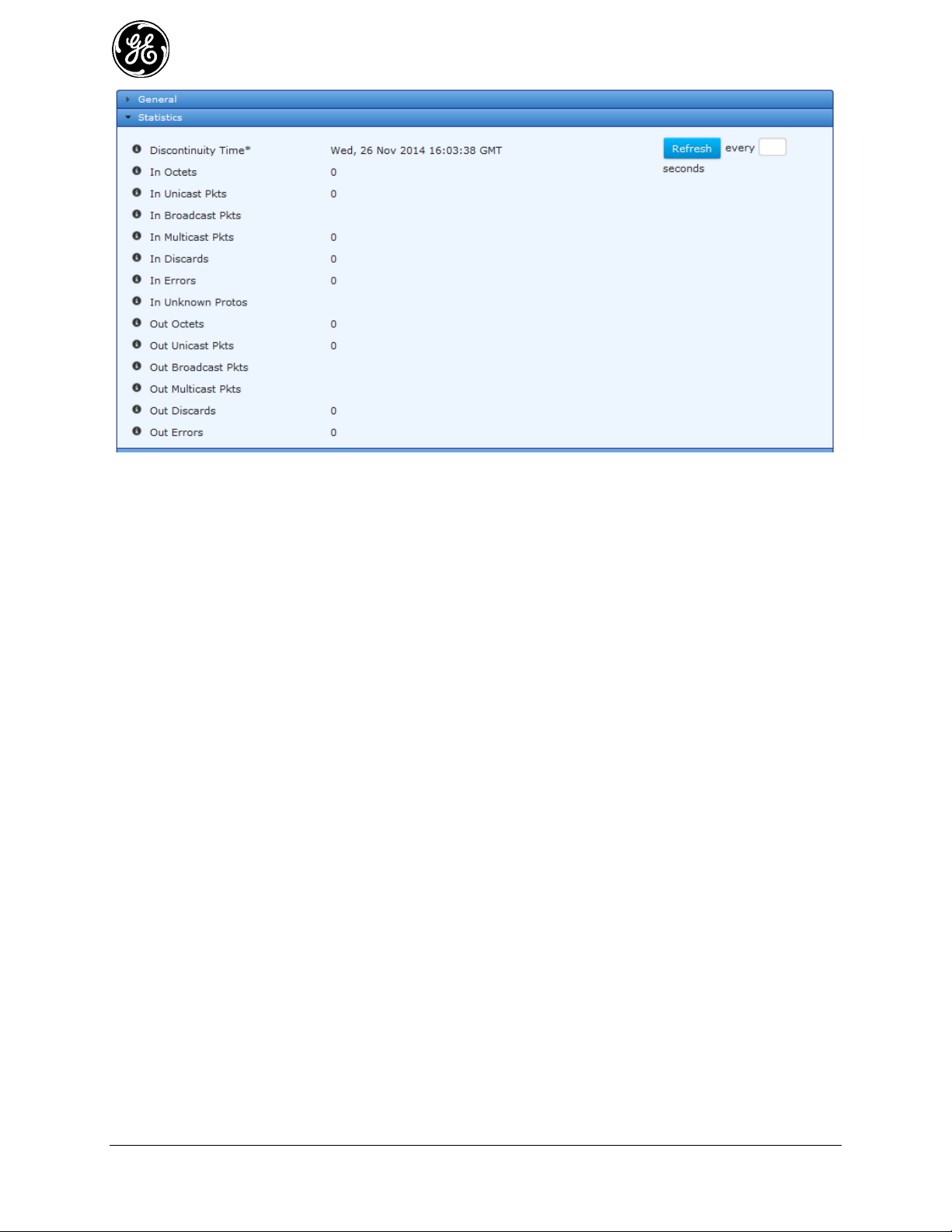
Figure 3-27. Cell Interface Statistics Screen
Discontinuity Time - The time on the most recent occasion at which any one or more of this
interface's counters suffered a discontinuity or interruption of service.
In Octets - The total number of octets received on the interface, including framing characters.
In Unicast Pkts - The number of packets, delivered by this sub-layer to a higher (sub-)layer,
which were not addressed to a multicast or broadcast address at this sub-layer.
In Broadcast Pkts - The number of packets, delivered by this sub-layer to a higher (sub-
)layer, which were addressed to a broadcast address at this sub-layer.
In Multicast Pkts - The number of packets, delivered by this sub-layer to a higher (sub-)layer,
which were addressed to a multicast address at this sub-layer.
In Discards - The number of inbound packets which were chosen to be discarded even though
no errors had been detected to prevent their being deliverable to a higher-layer protocol. One
possible reason for discarding such a packet could be to free up buffer space.
In Errors - For packet-oriented interfaces, the number of inbound packets that contained
errors preventing them from being deliverable to a higher-layer protocol.
In Unknown Protos - For packet-oriented interfaces, the number of packets received via the
interface which were discarded because of an unknown or unsupported protocol.
Out Octets - The total number of octets transmitted out of the interface, including framing
characters.
Out Unicast Pkts - The total number of packets that higher-level protocols requested be
transmitted, and which were not addressed to a multicast or broadcast address at this sub-layer,
including those that were discarded or not sent.
Out Broadcast Pkts - The total number of packets that higher-level protocols requested be
transmitted, and which were addressed to a broadcast address at this sub-layer, including those
that were discarded or not sent.
Out Multicast Pkts - The total number of packets that higher-level protocols requested be
transmitted, and which were addressed to a multicast address at this sub-layer, including those
that were discarded or not sent.
Out Discards - The number of outbound packets which were chosen to be discarded even
though no errors had been detected to prevent their being transmitted.
76 MDS Orbit MCR/ECR Technical Manual MDS 05-6632A01, Rev. G
Page 77

Out Errors - For packet-oriented interfaces, the number of outbound packets that could not be
transmitted because of errors.
3.5.2.1 Cell Status (Including the Module’s IMSI/IMEI)
When provisioning the cell module for network service, the cellular provider typically requires the
International Mobile Subscriber Identity code (IMSI) or International Mobile Station Equipment Identity
code (IMEI) to be provided. The Cell Status page contains this information.
Navigate to Interfaces / Cell ---> Status / Cellular
Figure 3-28. Cell Operational Status Screen
Imsi - International mobile subscriber identity
Imei - International mobile equipment identity
Iccid - Unique serial number of the SIM card
Mdn - Mobile directory number.
Apn - Access Point Name
App Sw Version - Application software version.
Modem Sw Version - Modem software version
Sim State - SIM state - (Inserted, Not Inserted)
Modem State - Device state of the cellular modem
Roaming State - Roaming state of the cellular modem
Service State - Service state of the cellular modem
Modem Type - This parameter identifies the type of modem inside the unit.
Rssi - Received signal strength indicator (dBm) of cellular modem.
Monitoring via the CLI
Ensure the CLI is in Operational mode.
MDS 05-6632A01, Rev. G MDS Orbit MCR/ECR Technical Manual 77
Page 78

Check cell status
The example on the following page shows cell status of a unit with 3G GSM modem operating on AT&T
network:
> show interfaces-state interface Cell cell-status
cell-status imsi 310410635138718
cell-status imei 351579050793072
cell-status iccid 89014103276351387185
cell-status mdn 15857544129
cell-status apn ccspbsc210.acfes.org
cell-status app-sw-version 0.0.5
cell-status modem-sw-version 12.00.024
cell-status sim-state ready
cell-status modem-state connected
cell-status roaming-state home
cell-status service-state hsdpa
cell-status rssi -71
The example below shows cell status of a unit with Verizon Wireless 4G LTE modem operating:
> show interfaces-state interface Cell cell-status
cell-status imsi 311480023786469
cell-status imei 990000947614196
cell-status iccid 89148000000234127091
cell-status mdn 5854724645
cell-status apn VZWINTERNET
cell-status app-sw-version 0.0.5
cell-status modem-sw-version "4.08.02 SVN 0 [2012-12-21 10:52:58]"
cell-status sim-state ready
cell-status modem-state connected
cell-status roaming-state home
cell-status service-state lte
cell-status rssi -52
Check Cell Statistics
> show interfaces-state interface Cell statistics
statistics discontinuity-time 2013-01-01T02:16:01+00:00
statistics in-octets 1218
statistics in-unicast-pkts 18
statistics in-multicast-pkts 0
statistics in-discards 0
statistics in-errors 0
statistics out-octets 774
statistics out-unicast-pkts 14
statistics out-discards 0
statistics out-errors 0
78 MDS Orbit MCR/ECR Technical Manual MDS 05-6632A01, Rev. G
Page 79

Check Cell IP Address
> show interfaces-state interface Cell ipv4
ipv4 forwarding true
ipv4 mtu 1500
PREFIX
IP LENGTH ORIGIN
-------------------------------------------------------------------------------------------------------------
166.130.200.173 32 static
LINK LAYER
IP ADDRESS ORIGIN STATE
---------------------------------------------------------------------------------------------------------------
0.0.0.0 19:00:00:00:d0:60 dynamic reachable
Determining the Cell Module’s IMSI/IMEI
When provisioning the cell module for network service, the cellular provider typically requires the
International Mobile Subscriber Identity code (IMSI) or International Mobile Station Equipment Identity
code (IMEI) to be provided. These codes can be determined by entering the following command:
> show interfaces-state interface Cell cell-status
where Cell is the configured name for the cellular device. Cell is the factory default name, but it may have
been changed by a previous user.
When the previous command is entered, a number of items are returned as shown in the example below.
The first two items (highlighted blue) show the IMSI and IMEI codes. These are unique for each unit.
cell-status imsi 311480023631413
cell-status imei 990000947608727
cell-status iccid 89148000000232694605
cell-status mdn 5857948168
cell-status apn VZWINTERNET
cell-status app-sw-version 0.0.5
cell-status modem-sw-version "4.08.02 SVN 0 [2012-12-21 10:52:58]"
cell-status sim-state Ready
cell-status modem-state connected
cell-status roaming-state home
cell-status service-state lte
cell-status rssi -62
3.5.2.2 Cell Modem Reprogramming
Understanding
The cell modem has its own set of firmware supplied by the wireless carrier. Occasionally new versions
of this firmware become available. The user has the option to upgrade the cell modem firmware if they
wish to do so.
GE posts new cell firmware at:
http://www.gegridsolutions.com/communications/mds/software.asp?directory=Orbit_MCR/Cell
MDS 05-6632A01, Rev. G MDS Orbit MCR/ECR Technical Manual 79
Page 80

Firmware compatible with North American MCR/ECR 4G LTE modules with FCC ID: N7NMC7355 /
IC ID: 2417C-MC7355 (see product bottom label)
cell-4g1-x.x.x.mpk = Orbit cell firmware image (4G1*), AT&T
cell-4g2-x.x.x.mpk = Orbit cell firmware image (4G2*), Rogers
cell-4g3-x.x.x.mpk = Orbit cell firmware image (4G3*), Telus
cell-4g4-x.x.x.mpk = Orbit cell firmware image (4G4*), Bell Canada
cell-4g5-x.x.x.mpk = Orbit cell firmware image (4G3*), Verizon Wireless
Firmware compatible with Europe, Middle East and APAC MCR/ECR 4G LTE modules:
cell-e4s-x.x.x.mpk = Orbit cell firmware image (E4S*), international - not carrier specific
cell-e42-x.x.x.mpk = Orbit cell firmware image (E42*), international - Telstra Specific
*Online store configuration string code corresponding to a 4G LTE carrier specific configuration
Configuring
To start reprogramming the cell modem firmware, navigate to the Reprogram Cellular Modem section.
The following example shows how to upload a cell modem firmware image file through the web browser
and reprogram the cel modem with that image file.
Navigate to Interfaces / Cell ---> Actions / Reprogram
Click on the Begin Reprogramming button once the file source is configured.
Figure 3-29. Reprogram Cellular Modem
The MCR supports file uploads through a web browser from a local file on the user’s PC. The MCR also
supports HTTP, FTP, TFTP, and SFTP file downloads using external remote servers.
File Source - File transfer method to use. Available choices are From Local File (DEFAULT),
From HTTP Server, From FTP Server, From TFTP Server, and From SFTP Server. Local file
uploads are only available through the web UI and not through the CLI
Local File - For a local file, the file to upload as chosen by the file dialog popped up by the
Select File... button
URL - For HTTP, the location of the source file
Server Address - For FTP, TFTP, and SFTP, the remote server's host name or IP address
File Path - For FTP, TFTP, and SFTP, the path to the source file on the remote server
User Name - For FTP and SFTP, the user name on the remote server
80 MDS Orbit MCR/ECR Technical Manual MDS 05-6632A01, Rev. G
Page 81

Password - For FTP and SFTP, the password on the remote server
Control Port - For FTP, the TCP control port (advanced setting - use default)
Data Port - For FTP, the TCP data port (advanced setting - use default)
Block Size - For TFTP, the block size as defined in RFP 2348 (advanced setting - use default)
Timeout - For FTP, TFTP, and SFTP, the timeout in seconds (advanced setting - use default)
The following example shows how to have the device download a cell modem firmware image (named
cell-4g5-1.0.2.mpk) from a TFTP server running on a host (address 192.168.1.10) that is accessible from
the MCR (e.g. a locally connected host or remote host accessible via cellular interface). To start
reprogramming the cell modem firmware from the CLI, enter the following command to download the
firmware image from the TFTP server:
> request interfaces interface Cell firmware reprogram filename cell-4g5-1.0.2.mpk manual-
file-server { tftp { address 192.168.1.10 } }
Monitoring - Reprogram
Once the reprogramming is begun, the process may be cancelled by clicking the Cancel
Reprogramming button. The current status of the reprogramming process is displayed on the web page.
Note that the web page does not display the current status if the device has not been instructed to
reprogram (in other words, if the state is “inactive”).
Figure 3-30. Reprogram Cellular Modem Monitoring
The reprogramming status contains the following items:
Current State – The status of the reprogramming task:
- inactive
- transfering
- processing
- cancelling
- complete
- failure
- cancelled
Detailed Message – The details regarding the operation, such as “Processing cellular modem
firmware image”
MDS 05-6632A01, Rev. G MDS Orbit MCR/ECR Technical Manual 81
Page 82

Application
Location
Frequency
Range
Gain
Antenna Description
GE MDS Part
Number
WiFi
Indoor
2.4-2.5 GHz
3.2 dBi
Direct Connect, RP SMA, Dipole
Whip
97-4278A34
WiFi
accessory
Indoor
--
--
Magnetic Mount, 5 ft./1.52 m
Cable, RP SMA Plug use with
above
97-4278A78
WiFi
Outdoor
2.4-2.5 GHz
2 dBi
External Mount, Omni Ant. with NMale connector - no cable
97-4278A48
WiFi
Outdoor
2.4-2.5 GHz
7.85
dBd
(10dBi)
Enclosed Yagi Ant.
with 18" coax to N-Female
connector
97-4278A01
WiFi
Outdoor
2.4-2.5 GHz
10.85
dBd
(13dBi)
Panel Ant. Linear,
Vertical/Horizontal with N-Female
connector - no cable
97-4278A16
Size – The total number of bytes in the image (not displayed on the web UI)
Bytes Transferred – The number of bytes already transferred or processed (not displayed on
the web UI)
Percent Complete – The percentage complete for the operation
To view the status of the reprogramming process in the CLI, ensure the CLI is in operational mode and
then follow the example below:
> show system firmware reprogram-status
system firmware reprogram-status state complete
system firmware reprogram-status detailed-message “Reprogrammed firmware
successfully. Modem will be restarted shortly.”
system firmware reprogram-status size 34849644
system firmware reprogram-status bytes-transferred 34849644
system firmware reprogram-status percent-complete 100
WiFi 3.5.3
Understanding
The Orbit MCR device may be configured to have an internal WiFi module that has FCC/CE modular
approval. The WiFi module can be configured to operate as an 802.11b/g/n Access Point or Station. The
specifications for the WiFi module are covered in “2.4 GHz WiFi Specifications” on Page 395. The table
below contains the list of GE MDS approved antennas.
Table 3-6. Approved Cell Antenna Types
The unit supports the following WiFi security modes:
None (should be used only to test connectivity) 1.
WPA2 + CCMP/AES Encryption – This mode should be used if all client devices support 2.
WPA2/CCMP.
CCMP/AES Encryption + TKIP Encryption – This mode should be used if there is mix of both 3.
legacy client devices that only support WPA/TKIP and newer devices that support WPA2/CCMP.
In this mode, stations must select only TKIP or AES/CCMP + TKIP. Stations cannot specify only
AES/CCMP. Table 3-7 shows the valid combinations of Station Encryption settings that will work for a
given AP Encryption setting.
82 MDS Orbit MCR/ECR Technical Manual MDS 05-6632A01, Rev. G
Page 83

Table 3-7: WPA Enterprise Combinations
AP Encryption
Station Encryption Choices
AES/CCMP
AES/CCMP
AES/CCMP + TKIP
TKIP
TKIP
AES/CCMP + TKIP
AES/CCMP + TKIP
TKIP
AES/CCMP + TKIP
Table 3-8. WiFi Interface LED Descriptions
LED - NIC1 or NIC2
State
Description
WiFi Interface
Off
Interface disabled
Access Point Mode
Solid Green
Solid Red
Operating as AP and at least one client connection
Operating as an AP and no client connection
Station Mode
Off
Solid Green
No connection
Wi-Fi connection established.
Also, WPA and WPA2 can be configured further in following modes:
Personal – This uses pre-shared keys (passphrases) configured on the MCR and client devices.
Enterprise – This supports EAP-TLS based authentication of client devices (configured with
certificates/keys) via RADIUS.
The default SSID is based on the unit’s serial number and takes the form of: GEMDS_<SERNUM> (the
serial number is printed on the chassis sticker). The default password for WiFi operation is
GEMDS_ORBIT.
The table below describes the Orbit MCR’s LED behavior when using the WiFi interface. The LED for
the NIC varies, depending on the configuration of the MCR. When equipped with 900 MHz support,
WiFi information is in NIC 1; otherwise, it is in NIC 2.
Configuring
Configuring the WiFi begins with the following UI:
Navigate to: Interfaces / Wi-Fi ---> Basic Config / Wi-Fi / Wifi Config
MDS 05-6632A01, Rev. G MDS Orbit MCR/ECR Technical Manual 83
Page 84

Figure 3-31. WiFi Mode /Power Configuration Screen
Mode - WiFi Mode
- Station - makes connection to a WiFi Access Point
- Access Point – provides WiFi connections to multiple Stations
Tx Power - The transmission power of the WiFi interface – Valid Values are 1 to 20 (dBm),
DEFAULT - 15 dBm.
3.5.3.1 AP Mode Configuration
To configure the parameters necessary for Access Point mode, start by using the following section of the
web UI:
Navigate to: Interfaces / Wi-Fi ---> Basic Config / Wi-Fi
Figure 3-32. WiFi AP SSID Configuration Screen
Each AP Profile contains specific information to be selected. For each SSID, however, certain parameters
are shared between each AP. The parameters are:
Channel – IEEE 802.11 channel number to operate on. Valid values 1-11, DEFAULT - 6.
Operation Mode - IEEE 802.11 mode to operate in.
84 MDS Orbit MCR/ECR Technical Manual MDS 05-6632A01, Rev. G
Page 85

- 802.11b
- 802.11g
- 802.11n
NOTE The following are advanced WiFi network settings and should only be modified with the
assistance of a network engineer.
Dtim Period – DTIM (delivery traffic information message) period. The number of beacons
between DTIMs. Valid Values: 1-255, DEFAULT - 2.
Rts Threshold – RTS/CTS Threshold. Valid Values 0-2347, DEFAULT - 2347 (disabled).
Fragm Threshold –Fragmentation Threshold. Valid Values 0-2346, DEFAULT - 2346
(disabled).
To add an AP, click on the ADD button, or to delete an AP, click on the SSID and then the Delete button.
By default, an access point will be configured with the SSID, GEMDS <SERNUM> and the WiFi
password, GEMDS-ORBIT. To edit an AP, click on the SSID of the configured network. In the
following example, the SSID is GEMDS_2344676.
Figure 3-33. WiFi AP Details Configuration Screen
Broadcast Ssid – If checked (true), the SSID will be broadcast.
Station Max – The maximum number of clients that will be allowed to connect to this access
point. Valid values: 1-max (7 = DEFAULT, max = 7 )
Station Timeout – The number of seconds a station may be inactive before the access point
will verify that the station is still within range. Valid values: 1-300 (300 = DEFAULT)
MDS 05-6632A01, Rev. G MDS Orbit MCR/ECR Technical Manual 85
Page 86

Beacon Interval – The number of seconds between WiFi beacon transmissions. Valid values:
15-65535. (100 = DEFAULT)
Privacy Mode – The privacy mode to use on this interface.
- None
- Wpa 2 Personal (DEFAULT)
- Wpa 2 Enterprise
- Wpa 2 Personal Mixed
- Wpa 2 Enterprise Mixed
Encryption – The encryption mode to use
- Ccmp - AES-based encryption mechanism that is stronger than TKIP for WPA2
- Tkip - a stream cipher is used with a 128-bit per-packet key, meaning that it dynamically
generates a new key for each packet for WPA
- Ccmp Tkip – allows a mixture of WPA and WPA2 clients
Key Mgmt – The type of preshared key to use
- Wpa Psk
- Wpa Psk sha 256
- Psk – The Preshared Key 8 to 64 characters, DEFAULT = <blank>.
Vlan Mode – VLAN configuration for the WiFi Interface
- None
- Access - Only one VLAN can be configured on an access interface; traffic carried for
only one VLAN.
- Trunk - Two or more VLANs configured on a trunk port; several VLANs can be carried
simultaneously.
NOTE Remember to click on SAVE when finished.
The CLI commands below show how the WiFi settings are made. The unit must be in Configuration
Mode to make these settings. Each command string begins with the word set:
% set interfaces interface Wi-Fi wifi-config mode access-point ap-config ap GEMDS_<SERNUM>
broadcast-ssid true privacy-mode wpa2-personal psk-config psk GEMDS_ORBIT
3.5.3.2 Dual-SSID Functionality (AP mode only)
The Orbit MCR supports up to two SSIDs to be configured when the Wi-Fi interface is set to an Access
Point. The first SSID should be reserved for high throughput data paths. The second SSID is intended to
support auxiliary applications such as a dedicated management connection or guest LAN access. The
following example demonstrates having a second Wi-Fi AP with the SSID:
86 MDS Orbit MCR/ECR Technical Manual MDS 05-6632A01, Rev. G
Page 87

Figure 3-34. WiFi AP Configuration
To set up a second WiFi access point with the CLI, use the following command by substituting the
different SSID and PSK for the new configuration.
% set interfaces interface Wi-Fi wifi-config mode access-point ap-config channel 3 operation-
mode 80211n ap GEMDS_2_<SERNUM> broadcast-ssid true privacy-mode wpa2-personal
psk-config psk GEMDS_ORBIT2 encryption ccmp-tkip
Operational Notes Regarding Dual SSID
The channel, operation mode, tx-power, dtim-period, rts-threshold and fragm-threshold
parameters are shared between the two SSIDs.
The Orbit MCR organizes the SSIDs in alphabetical order. If an SSID of ssidexample exists
and a second SSID of examplessid is created, this will become the first SSID and the SSID
ssidexample will become the second SSID.
Each SSID is independent of the other, except for the parameters noted above. Each SSID can
be in or out of the bridge. However, to use VLANs, the SSIDs must be bridged.
3.5.3.3 Station Mode
To configure the WiFi interface as a station, start at the following:
Navigate to: Interfaces / Wi-Fi ---> Basic Config / Wi-Fi
Figure 3-35. WiFi Station Configuration
Mode - WiFi Mode
- Station - makes connection to a WiFi Access Point
- Access Point – provides WiFi connections to multiple Stations
Tx Power - The transmission power of the WiFi interface – Valid Values 1 to 20 (dBm),
DEFAULT - 15 dBm.
Select Station from the drop down. In Station Config, add a new AP by clicking on the ADD button. Enter
the SSID of the AP to have the station associate to it. Then, click on the ADD button to enter additional
details about the Wi-Fi AP.
In the following example, the SSID of SOMESSID is used.
MDS 05-6632A01, Rev. G MDS Orbit MCR/ECR Technical Manual 87
Page 88

Navigate to: Interfaces / Wi-Fi ---> Basic Config / Wi-Fi
Figure 3-36. WiFi Configuration Settings
Enabled – Check the box to enable the WiFi interface.
Privacy Mode – The privacy mode to use on this interface.
- None (DEFAULT)
- Wpa 2 Personal
- Wpa 2 Enterprise
- Wpa 2 Personal Mixed
- Wpa 2 Enterprise Mixed
Encryption – The encryption mode to use
- Ccmp - AES-based encryption mechanism that is stronger than TKIP for WPA2
- Tkip - a stream cipher is used with a 128-bit per-packet key, meaning that it dynamically
generates a new key for each packet
- Ccmp Tkip – allows a mixture of WPA and WPA2 clients
Key Mgmt – The type of preshared key to use
- Wpa Psk
- Wpa Psk sha 256
Psk – The Preshared Key 8 to 64 characters, DEFAULT = <blank>.
NOTE Remember to click on the Save button when finished.
Monitoring:
General WiFi status information
The following UI screens are read-only. Navigate to: Interfaces / Wi-Fi ---> Status / General
88 MDS Orbit MCR/ECR Technical Manual MDS 05-6632A01, Rev. G
Page 89

Figure 3-37. WiFi Status Information
Type - The type of the interface
Admin Status - The desired state of the interface. (“Up” - meaning operational)
Oper Status - The current operational state of the interface.
NOTE The following information is useful for are advanced WiFi users for debugging.
If Index - The if Index value for the if Entry represented by this interface. Valid values: 1—
2147483647
Phys Address- The interface's address at its protocol sub-layer. For example, for an 802.x
interface, this object normally contains a MAC address. The interface's media-specific
modules must define the bit and byte ordering and the format of the value of this object. For
interfaces that do not have such an address (e.g., a serial line), this node is not present.
Figure 3-38. WiFi Statistics Information
NOTE The following information is reset on system reboot or power cycle.
Discontinuity Time - The time on the most recent occasion at which one or more of this
interface's counters suffered a discontinuity.
In Octets - The total number of octets received on the interface, including framing characters.
In Unicast Pkts - The number of packets, delivered by this sub-layer to a higher (sub-) layer,
which were not addressed to a multicast or broadcast address at this sub-layer.
MDS 05-6632A01, Rev. G MDS Orbit MCR/ECR Technical Manual 89
Page 90

In Broadcast Pkts - The number of packets, delivered by this sub-layer to a higher (sub-)
layer, which were addressed to a broadcast address at this sub-layer.
In Multicast Pkts - The number of packets, delivered by this sub-layer to a higher (sub-)
layer, which were addressed to a multicast address at this sub-layer.
In Discards - The number of inbound packets which were chosen to be discarded even though
no errors had been detected to prevent their being deliverable to a higher-layer protocol. One
possible reason for discarding such a packet could be to free up buffer space.
In Errors - For packet-oriented interfaces, the number of inbound packets that contained
errors preventing them from being deliverable to a higher-layer protocol.
In Unknown Protos - For packet-oriented interfaces, the number of packets received via the
interface which were discarded because of an unknown or unsupported protocol.
Out Octets - The total number of octets transmitted out of the interface, including framing
characters.
Out Unicast Pkts - The total number of packets that higher-level protocols requested be
transmitted, and which were not addressed to a multicast or broadcast address at this sub-layer,
including those that were discarded or not sent.
Out Broadcast Pkts - The total number of packets that higher-level protocols requested be
transmitted, and which were addressed to a broadcast address at this sub-layer, including those
that were discarded or not sent.
Out Multicast Pkts - The total number of packets that higher-level protocols requested be
transmitted, and which were addressed to a multicast address at this sub-layer, including those
that were discarded or not sent.
Out Discards - The number of outbound packets which were chosen to be discarded even
though no errors had been detected to prevent their being transmitted.
Out Errors - For packet-oriented interfaces, the number of outbound packets that could not be
transmitted because of errors.
3.5.3.4 WiFi Status When Configured as an AP:
Figure 3-39. WiFi AP Status Information
Serial Number – Internal WiFi module serial number
Mode - WiFi Mode
- Station - makes connection to a WiFi Access Point
- Access Point – provides WiFi connections to multiple Stations
Tx Power - The transmission power of the WiFi interface – Valid Values 1-18 (dBm)
Channel – IEEE 802.11 channel number to operate on. Valid values 1-11.
Ap Status - link to information regarding the Ap linked to this station - as shown below
90 MDS Orbit MCR/ECR Technical Manual MDS 05-6632A01, Rev. G
Page 91

3.5.3.5 WiFi AP Status:
Figure 3-40. WiFi AP Status Information
Mac - Hardware Id of connected device.
Rssi - Received Signal Strength Indication - possible values are: -20 to -90 dBm
Authenticated – indicates the client is valid to connect - True/False
Authorized – indicates the client has valid logon credentials - True/False
Inactive – milliseconds since last packet
Rxbytes – received byte count
Rxpackets – received packet count
3.5.3.6 WiFi Status When Configured as a Station:
Figure 3-41. WiFi Station Statistics Information
Ssid - SSID of access point to which the unit is connected - up to 32 characters.
Bssid – Basic SSID of access point to which the unit is connected - up to 32 characters
Rssi - Received Signal Strength Indication - possible values are: -20 to -90 dBm
Authenticated – indicates the client is valid to connect - True/False
Authorized – indicates the client has valid logon credentials - True/False
Inactive – milliseconds since last packet
MDS 05-6632A01, Rev. G MDS Orbit MCR/ECR Technical Manual 91
Page 92

Rxbytes – Received byte count
Rxpackets – Received packet count
Txbitrate – Transmit bit rate
Txbytes – Transmitted byte count
Txpackets – Transmitted packet count
Txfailed – Transmit packet failures
Txretries – Transmit packet retries
3.5.3.7 Using CLI Commands
AP Mode Configuration
The following will configure a basic access point with an SSID of somessid running in 802.11g mode to
verify connectivity:
% set interfaces interface Wi-Fi wifi-config mode access-point ap-config operation-mode
80211g ap somessid
% show interfaces interface Wi-Fi wifi-config | details
mode access-point;
tx-power 15;
ap-config {
ap somessid {
broadcast-ssid true;
station-max 7;
station-timeout 300;
beacon-interval 100;
privacy-mode none;
vlan-mode none;
}
channel 6;
operation-mode 80211g;
dtim-period 2;
rts-threshold 2347;
fragm-threshold 2346;
}
Privacy Mode Configuration via CLI
The default privacy mode is
none.) The following configures the unit to use WPA2-Personal security with the default of CCMP/AES
encryption and disables the broadcasting of the SSID.
% set interfaces interface Wi-Fi wifi-config ap-config ap somessid broadcast-ssid false privacy-
mode wpa2-personal psk-config psk somepassphrase encryption ccmp
% show interfaces interface Wi-Fi wifi-config | details
mode access-point;
tx-power 15;
ap-config {
ap somessid {
broadcast-ssid false;
station-max 7;
station-timeout 300;
beacon-interval 100;
privacy-mode wpa2-personal;
92 MDS Orbit MCR/ECR Technical Manual MDS 05-6632A01, Rev. G
wpa2-personal
. (The privacy mode in the previous example was set to
Page 93

psk-config {
encryption ccmp;
key-mgmt wpa-psk;
psk somepassphrase;
}
vlan-mode none;
}
channel 6;
operation-mode 80211g;
dtim-period 2;
rts-threshold 2347;
fragm-threshold 2346;
}
The next example takes the previous configuration and changes the security to WPA2-Personal with
CCMP/AES + TKIP encryption.
% set interfaces interface Wi-Fi wifi-config ap-config ap somessid broadcast-ssid false privacy-
mode wpa2-personal psk-config psk somepassphrase encryption ccmp-tkip
% show interfaces interface Wi-Fi wifi-config | details
mode access-point;
tx-power 15;
ap-config {
ap somessid {
broadcast-ssid false;
station-max 7;
station-timeout 300;
beacon-interval 100;
privacy-mode wpa2-personal;
psk-config {
encryption ccmp-tkip;
key-mgmt wpa-psk;
psk somepassphrase;
}
vlan-mode none;
}
channel 6;
operation-mode 80211g;
dtim-period 2;
rts-threshold 2347;
fragm-threshold 2346;
}
Other configurations
The following configures the device to broadcast its SSID, support 802.11b/g/n modes and operate on
channel 3.
% set interfaces interface Wi-Fi wifi-config ap-config operation-mode 80211n channel 3 ap
somessid broadcast-ssid true privacy-mode wpa2-personal psk-config psk somepassphrase
encryption ccmp-tkip
% show interfaces interface Wi-Fi wifi-config | details
mode access-point;
MDS 05-6632A01, Rev. G MDS Orbit MCR/ECR Technical Manual 93
Page 94

tx-power 15;
ap-config {
ap somessid {
broadcast-ssid true;
station-max 7;
station-timeout 300;
beacon-interval 100;
privacy-mode wpa2-personal;
psk-config {
encryption ccmp-tkip;
key-mgmt wpa-psk;
psk somepassphrase;
}
vlan-mode none;
}
channel 3;
operation-mode 80211n;
dtim-period 2;
rts-threshold 2347;
fragm-threshold 2346;
}
Dual-SSID Functionality (AP mode only)
The Orbit MCR supports up to two SSIDs to be configured when the Wi-Fi interface is set to an Access
Point. The first SSID should be reserved for high throughput data paths. The second SSID is intended to
support auxiliary applications such as a dedicated management connection or guest LAN access. The
following example sets up a second Wi-Fi AP with the SSID of somessid2 to the previous example’s
SSID somessid.
% set interfaces interface Wi-Fi wifi-config mode access-point ap-config channel 3 operation-
mode 80211n ap somessid2 broadcast-ssid true privacy-mode wpa2-personal psk-config
psk somepassphrase2 encryption ccmp-tkip
% show interfaces interface Wi-Fi wifi-config | details
mode access-point;
tx-power 15;
ap-config {
ap somessid {
broadcast-ssid true;
station-max 7;
station-timeout 300;
beacon-interval 100;
privacy-mode wpa2-personal;
psk-config {
encryption ccmp-tkip;
key-mgmt wpa-psk;
psk somepassphrase;
}
vlan-mode none;
}
ap somessid2 {
broadcast-ssid true;
station-max 7;
94 MDS Orbit MCR/ECR Technical Manual MDS 05-6632A01, Rev. G
Page 95

station-timeout 300;
beacon-interval 100;
privacy-mode wpa2-personal;
psk-config {
encryption ccmp-tkip;
key-mgmt wpa-psk;
psk somepassphrase2;
}
vlan-mode none;
}
channel 3;
operation-mode 80211n;
dtim-period 2;
rts-threshold 2347;
fragm-threshold 2346;
}
Operational Notes Regarding Dual SSID
The channel, operation mode, tx-power, dtim-period, rts-threshold and fragm-threshold parameters
are shared between the two SSIDs.
The Orbit MCR organizes the SSIDs in alphabetical order. If an SSID of somessid exists and a
second SSID of somessid2 is created, this will become the first SSID and the SSID somessid2 will
become the second SSID.
Each SSID is independent of the other, except for the parameters noted above. Each SSID can be in
or out of the bridge. However, to use VLANs, the SSIDs must be bridged.
Station Mode
This sets the unit to act as a WiFi station to connect to an AP with somessid and WPA2 Personal security.
% set interfaces interface Wi-Fi wifi-config mode station station-config ap somessid enabled
true privacy-mode wpa2-personal psk-config psk somepassphrase encryption ccmp
% show interfaces interface Wi-Fi | details
enabled true;
wifi-config {
mode station;
tx-power 15;
station-config {
ap somessid {
enabled true;
privacy-mode wpa2-personal;
psk-config {
encryption ccmp;
key-mgmt wpa-psk;
psk somepassphrase;
}
}
}
}
type wifi;
MDS 05-6632A01, Rev. G MDS Orbit MCR/ECR Technical Manual 95
Page 96

Monitoring
Ensure the CLI is in Operational mode.
Access Point Mode
The examples on the following pages shows status and statistics of the WiFi interface with two stations
connected.
> show interfaces-state interface Wi-Fi wifi-status
wifi-status serial-number n722m3anu000867
wifi-status mode "Access Point"
wifi-status tx-power 15
wifi-status channel 4
wifi-status ap-status ap MDS_ORBIT
client 00:0e:35:ba:67:36
rssi -65
authenticated true
authorized true
inactive 16940
rxbytes 29134
rxpackets 622
txbitrate 1
txbytes 25987
txpackets 265
txfailed 0
txretries 0
> show interfaces-state interface Wi-Fi statistics
statistics discontinuity-time 2013-09-24T13:12:25-04:00
statistics in-octets 3747
statistics in-unicast-pkts 26
statistics in-multicast-pkts 0
statistics in-discards 0
statistics in-errors 0
statistics out-octets 55511
statistics out-unicast-pkts 215
statistics out-discards 0
statistics out-errors 0
Station Mode
The following shows status when connected to a configured Wi-Fi AP.
> show interfaces-state interface Wi-Fi wifi-status
wifi-status serial-number N722M33NU000628
wifi-status mode Station
wifi-status tx-power 15
wifi-status channel 4
wifi-status station-status ssid somessid
wifi-status station-status bssid 00:19:70:2c:40:3f
wifi-status station-status rssi -58
wifi-status station-status authenticated true
wifi-status station-status authorized true
wifi-status station-status inactive 29270
wifi-status station-status rxbytes 27119
96 MDS Orbit MCR/ECR Technical Manual MDS 05-6632A01, Rev. G
Page 97

wifi-status station-status rxpackets 564
wifi-status station-status txbitrate 54
wifi-status station-status txbytes 897
wifi-status station-status txpackets 9
wifi-status station-status txfailed 0
wifi-status station-status txretries 0
> show interfaces-state interface Wi-Fi statistics
statistics discontinuity-time 2013-09-24T13:12:25-04:00
statistics in-octets 288
statistics in-unicast-pkts 2
statistics in-multicast-pkts 0
statistics in-discards 0
statistics in-errors 0
statistics out-octets 752
statistics out-unicast-pkts 7
statistics out-discards 0
statistics out-errors 0
Unlicensed 900 MHz ISM (NX915) 3.5.4
Understanding
The 900 MHz ISM Module (NX915) interface provides operation in the 900 MHz unlicensed ISM band.
The module provides long-distance communications with data rates ranging from 125 kbps to 1.25 Mbps,
suitable to interface both Ethernet and Serial controllers such as PLCs, RTUs and SCADA systems. The
module utilizes a combination of FHSS (Frequency Hopping Spread Spectrum), DTS (Digital
Transmission System) and hybrid FHSS/DTS technologies to provide dependable wireless
communications.
The GE MDS NX915 NIC module is a point-to-multipoint, medium speed, long range (>20 miles),
spread-spectrum, wireless data transmission product. It operates as a Frequency-Hopping Spread
Spectrum (FHSS) or a Digital Transmission System (DTS) in the 902 to 928 MHz license-free ISM band.
The NIC can operate as an Access Point, a Remote, or a Store and Forward (SAF) device. It will operate
as an intentional radiator in accordance with FCC Rule Part 15.247 under full modular rules per DA 00-
1407.
The specifications for the 900 MHz NX915 NIC module:
Frequency Range: 902 to 928 MHz
Power Output: 20 dBm to 30 dBm in 1.0 dBm steps (DEFAULT = 30 dBm)
Output Impedance: 50 Ohms
Permissible Antennas: See Table 3-10 below
Antenna Connector: TNC female
Number of Frequency Channels: Selectable 50 to 81 for FHSS, 1 to 18 for DTS
Channel Separation: 307.5 kHz minimum
Modulation Type: 2-Level GFSK / 4-Level GFSK
Data Rates: 125, 250, 500, 1000, 1000W, 1250 kbps
Peak Frequency Deviation: 1250 kbps / 4-level GFSK: 550 kHz
Beacon Interval: 10 to 300 ms (DEFAULT is 150)
Dwell Time: 10 to 400 ms (DEFAULT is 50)
MDS 05-6632A01, Rev. G MDS Orbit MCR/ECR Technical Manual 97
Page 98

Table 3-9. Modulation and Bandwidth Combinations
125
250
500
1000N*
1000W*
1250
Mode
FHSS
FHSS
DTS
DTS
DTS
DTS
Rate (kbps)
125
250
500
1000
1000
1250
Channels
80
80
27
18
15
13
Modulation
2-GFSK
2-GFSK
2-GFSK
4-GFSK
4-GFSK
4-GFSK
RF Bandwidth
152 kHz
(20dB)
300 kHz
(20dB)
505 kHz
(6 dB)
680 kHz
(6 dB)
933 kHz
(6 dB)
1320 kHz
(6 dB)
Sensitivity 1x10⁶
-105 dBm
-103 dBm
-99 dBm
-92 dBm
-95 dBm
-95 dBm
Application
Location
Frequency
Range
Gain
Antenna Description
GE MDS Part
Number
900 MHz
(NX915)
Indoor
902-928MHz
2 dBi
Omni Indoor Flex
97-2952A01
900 MHz
(NX915)
Indoor
902-928MHz
5 dBi
Omni with 16” N-F Connect and
Mount
97-3194A16
900 MHz
(NX915)
Outdoor
902-960MHz
10 dBd
(12.15
dBi)
Yagi 6 Element, N-Female - no cable
97-3194A14
900 MHz
(NX915)
Outdoor
902-960MHz
10 dBd
(12.15
dBi)
Yagi 6 Element, N-Female - with 10’
Jumper N-M and Mount
97-3194A14A
900 MHz
(NX915)
Outdoor
902-960MHz
10 dBd
(12.15
dBi)
Yagi 6 Element, N-Female - with 15’
Jumper N-M and Mount
97-3194A14B
900 MHz
(NX915)
Outdoor
902-960MHz
6.4 dBd
(8.55 dBi)
Yagi 3 Element N-Female - no cable
97-3194A13
900 MHz
(NX915)
Outdoor
902-960MHz
6.4 dBd
(8.55 dBi)
Yagi 3 Element N-Female – with 10’
Jumper N-M and Mount
97-3194A13A
FCC Part 15.247 under modular rules per DA00-1407
FCC ID: E5MDS-NX915
ICID: 101D-NX915
Six modulation rate / bandwidth combinations; as seen in Table 3-9:
*1000N occupies 250 kHz less spectrum bandwidth than 1000W which is why it has a "narrower bandwidth", this
comes with a ~2-3 dBm reduction in sensitivity when compared to 1000W kbps. For clear spectrum, use 1000W, for
unknown or busy spectrum it's safer to use the narrow 1000N modem.
Table 3-10. Approved NxRadio Antenna Types
98 MDS Orbit MCR/ECR Technical Manual MDS 05-6632A01, Rev. G
Page 99

900 MHz
(NX915)
Outdoor
902-960MHz
6.4 dBd
(8 55 dBi)
Yagi 3 Element N-Female – with 15’
Jumper N-M and Mount
97-3194A13B
900 MHz
(NX915)
Outdoor
902-960MHz
6.4 dBd
(8.55 dBi)
Yagi 3 Element N-Female – with 25’
Jumper N-M and Mount
97-3194A13C
900 MHz
(NX915)
Outdoor
902-928MHz
7 dBd
(9.15 dBi)
5/8-wavelength Omni Ant. with 16"
coax to N-Female connector
97-3194A17
For the 900MHz radio (NX915) – If the installed antenna network does not provide the proper load matching, an
Selected Modem Modes
Hop Set / Channels
125
250
500
1000
1000W
1250
A
80
80
27
18
15
13
B
0 0 27
20
15
12
C
0 0 26
20
16
12
D
0 0 0
20
16
13
E
0 0 0 0 16
13
F
0 0 0 0 0
13
alarm is generated by the unit to indicate a VSWR Error condition. This must be corrected in order for the radio to
operate properly and to ensure optimal operation.
NOTE The only required steps for basic configuration are programing a network name in all units and
establishing one unit as the AP.
Minimal configuration is necessary but several advanced tuning facilities are provided.
Frequency operating range is restricted by pre-set factory calibration to ensure compliance with
applicable country-specific regulatory requirements. Frequency operating range can be further restricted
by user input to avoid select portions of the operating band. This is sometimes helpful when attempting to
collocate a network with another 900MHz network, such as the MDS iNET or TransNET. For example
the iNET network can be configured to operate in the top half of the band while the Orbit can have its
NX915 module configured for the lower half.
By default the radio ships from the factory with the 500kbps modem selected. Dwell time is set to 50ms
and Hop Set A is enabled. For typical configuration (e.g., North America) this provides 27 discrete
channels over which to hop.
Hop Sets provide a way of specifying the minimum channel spacing within the band and implicitly define
the maximum number of hops. Hop Set A uses 307.5 kHz spacing and provides 80 channels. (Required
for Modem selections 125kbps and 250kbps).
Table 3-11. Selected Modem Modes
See “APPENDIX F – NX915 Module Frequencies” on Page 430 for a chart listing RF
channels/frequencies in each hop set, as they apply to each modem selection.
Other items of interest for tuning configuration include Modem Mode (125kbps, 250kbps, 500kbps, etc.)
and dwell time. For remotes, setting modem mode to “auto” allows remotes to automatically follow the
configuration of the AP. Setting the remote to use a specific modem trades faster sync times for system
flexibility. Dwell time determines how frequently the radio switches channels. Longer dwell times are
more efficient for data transport and provide higher throughput; but smaller dwell times provide faster
synchronization and are more robust in weak signal environments or in the presence of interferers.
MDS 05-6632A01, Rev. G MDS Orbit MCR/ECR Technical Manual 99
Page 100

Table 3-12. Country Limitations Example
Country
Limitation
Brazil
Operate only in the band 902-907 and 915-928 MHz
Australia/Chile
Operate only in the band 915-928 MHz
New Zealand
Operate only in the band 921-928 MHz
LED - NIC2
State
Description
NxRadio Interface
Off
Interface disabled
Access Point Mode
Blink Red
Solid Red
Solid Green
NIC Initialization
No Remotes connected
Linked with at least 1 Remote
Remote Mode
Blink Red
Solid Green
NIC Initialization / Not linked to an Access Point
Linked with Access Point
For the advanced user, the module supports configuring more items including:
Data Retries - Number of times to retry unicast data before declaring NACK.
Fragment Threshold - Fragmentation threshold
Lna State - Controls the low noise amplifier
Mcast Repeat - Number of times to repeat downstream broadcast and multicast data.
Propagation Delay - Correction for the propagation delay of the RF signal.
Stale Packet Timeout - If the MAC is unable to transmit a packet in this time, it will drop the packet.
In general, it is recommended that users start with the simplest configuration and then make parameter
changes as necessary to meet specific needs.
NOTE Frequency blocking to meet country specific regulatory requirements may be configured for by
the factory to disallow operation. These settings can NOT be changed or modified by the user.
See the table below:
Table 3-13. NxRadio Interface LED Descriptions
Important Notes and Information Regarding LQI
LQI is dependent on the modulation format and should be used as a relative measurement of the link
quality. A low LQI value indicates a better link quality than a high value. Algorithmically, using GFSK
modulation, the transceiver calculates the value by measuring the frequency of each "bit" and compares it
with the expected frequency based on the channel frequency and the deviation and the measured
frequency offset.
- LQI is a metric of the quality of the received signal. It is a dynamic value that is computed only
when data is received on the RF interface, and should be refreshed accordingly.
- Unlike RSSI which simply measures signal strength, LQI is only a measurement of the
"correctness" of this signal. (This means how easily the received signal can be correctly
demodulated.)
- In general the lower the LQI the better the quality.
- LQI should be used as a "relative" measurement. Precision is fairly loose and subject to
variation from radio to radio and modulation format.
100 MDS Orbit MCR/ECR Technical Manual MDS 05-6632A01, Rev. G
 Loading...