

Page 1
MDS SD Series
Secure, Long Range IP/Ethernet & Serial
Technical Manual
Covering ES/SS Units with Firmware Version 4.3.x
Applies to all models EXCEPT
operation, refer to Publication 05-4670A01.
MDS 05-4846A01, Rev. G
those operated in x710 Mode. For x710 mode
July 2012
t
a
Fe
Installation and Operation Guide
d
e
s
a
B
-
b
e
W
ng
i
r
u
D
M
e
c
i
v
e
r
ge
a
n
a
Page 2

Quick-Start instructions for this product are contained in publication 05-4847A01.
All GE MDS manuals and updates are available online at www.gemds.com.
Page 3

TABLE OF CONTENTS
1.0 INTRODUCTION ............................................................................................................ 1
1.1 Conventions Used in This Manual ..........................................................................................1
2.0 PRODUCT DESCRIPTION............................................................................................. 3
2.1 Front Panel Connectors and Indicators .................................................................................. 3
2.2 Key Product Features ............................................................................................................. 4
Media Access Control (MAC).................................................................................................... 4
VLAN Capability........................................................................................................................ 5
Terminal Server Capability........................................................................................................ 5
Store and Forward Capability....................................................................................................5
2.3 SD Model Offerings ................................................................................................................ 6
2.4 Operating Modes and Applicable Manuals ............................................................................. 6
2.5 Accessories and Spares ......................................................................................................... 7
Protected Network Station........................................................................................................ 7
Dual Protected Configurations.................................................................................................. 8
3.0 TYPICAL APPLICATIONS............................................................................................ 10
3.1 Operating Parameters .......................................................................................................... 10
3.2 Example Systems ..................................................................................................................11
Multiple Address Systems (MAS) ............................................................................................11
Point-to-Point System..............................................................................................................11
IP/Ethernet Polling and Terminal Server Operation................................................................ 12
Port Sharing with Multiple Hosts............................................................................................. 13
Push Communication (Report-by Exception).......................................................................... 14
IP Polling of Serial Remotes................................................................................................... 14
Serial Remotes with Two Serial Ports..................................................................................... 15
4.0 INSTALLATION PLANNING ......................................................................................... 17
4.1 Mounting Options ................................................................................................................. 18
Optional DIN Rail Mounting .................................................................................................... 18
4.2 Antennas and Feedlines ....................................................................................................... 19
Antennas................................................................................................................................. 19
Feedlines ................................................................................................................................ 19
4.3 DC Power Connection .......................................................................................................... 20
4.4 Grounding Considerations .................................................................................................... 21
4.5 Ethernet Data Interface (RJ-45) ........................................................................................... 21
4.6 Serial Data Interfaces ........................ ... ... ... .... ... ... ... .... ... ... ... ................................................ 22
COM1 (Serial) Connection...................................................................................................... 22
COM2 (Data) Connections...................................................................................................... 24
5.0 STEP-BY-STEP INSTALLATION.................................................................................. 26
MDS 05-4846A01, Rev. G SD Series Technical Manual i
Page 4

5.1 Initial Configuration ............................................................................................................... 27
Web-Based Management....................................................................................................... 27
Alternative Management Methods....................... ................................................................... 27
Web Browser Connection ....................................................................................................... 28
5.2 Initial Startup & Checkout ............................................ ... ... ... .... ... ... ... ... .... ............................ 30
Ethernet Connector LEDs....................................................... .... ... ... ... ... .... ... ... ... .... ............... 31
5.3 Optimizing the Radio Network .............................................................................................. 31
Modem Type Setting............................................................................................................... 31
Inter-Packet Gap Settings.......................................................................................................32
Baud Rate Setting................................................................................................................... 32
Ethernet Settings ....................................... ... .... ...................................... .... ... ... ... .... ... ... ......... 32
Antenna SWR Check.............................................................................................................. 33
6.0 USING THE DEVICE MANAGER................................................................................. 34
6.1 Navigating the Screens ........................................................................................................ 34
Overview Screen..................................................................................................................... 35
6.2 Management Tasks .............................................................................................................. 36
6.3 Configuration Screens .......................................................................................................... 41
Radio....................................................................................................................................... 41
Store and Forward Operation.................................................................................................. 45
Features.................................................................................................................................. 50
Understanding the Use of Virtual Radio Channels (VRCs)..................................................... 55
Using the Terminal Server—Typical Example......................................................................... 58
Communications Ports............................................................................................................62
Security................................................................................................................................... 65
6.4 Maintenance & Status Screen ..............................................................................................68
Event Log................................................................................................................................ 68
Alarm Summary......................... ... ....................................... ... .... ... ... ... ... .... ... ......................... 69
Performance ........................................................................................................................... 71
Radio Test............................................................................................................................... 73
Firmware Utilities .................................................................................................................... 76
Configuration Files......................................................... ... ... ... .... ... ......................................... 80
7.0 TROUBLESHOOTING................................................................................................. 83
7.1 LED Indicators ...................................................................................................................... 84
7.2 Checking for Alarms/Events ................................................................................................. 85
Major Alarms vs. Minor Alarms............................................................................................... 85
Status and Informational Events............................................................................................. 85
Event Code Definitions ........................................................................................................... 86
7.3 Operating Constraints ........................................................................................................... 87
8.0 TECHNICAL REFERENCE ..........................................................................................89
8.1 Performing Network-Wide Remote Diagnostics ................................................ .... ... ... ... ... ... 89
Setting Up Diagnostics............................................................................................................ 90
8.2 Over-the-Air Firmware Upgrades ......................................................................................... 90
Intrusive vs. Passive (Non-Intrusive) Mode ............................................................................ 91
OTA Reprogramming Overview.............................................................................................. 92
Cancelling OTA Reprogramming............................................................................................ 93
Error Conditions/Recovery...................................................................................................... 93
ii SD Series Technical Manual MDS 05-4846A01, Rev. G
Page 5
Execution and Screen Examples............................................................................................ 93
RF Exposure
l'exposition aux RF
8.3 COM1 Operating Modes ...................................................................................................... 94
Changing COM1 Modes ......................................................................................................... 94
8.4 Implementing Sleep Mode .................................................................................................... 95
8.5 User-Programmable I/O Functions ....................................................................................... 96
8.6 Technical Specifications ...................................................................................................... 96
8.7 dBm-Watts-Volts Conversion Chart ...................................................................................... 99
9.0 GLOSSARY OF TERMS & ABBREVIATIONS ........................................................... 100
Copyright and Trademark
This manual and all software described herein is protected by Copyright: 2012 GE MDS, LLC. All
rights reserved. GE MDS, LLC reserves its right to correct any errors and omissions in this publi-
®
cation. Modbus
is a registered trademark of Schneider Electric Corporation. All other trademarks
and product names are the property of their respective owners.
RF Safety Notice (English and French)
Concentrated energy from a directional antenna may pose a health hazard to
humans. Do not allow people to come closer to the antenna than the distances
listed in the table below when the transmitter is operating. More information on
RF exposure can be found online at the following website:
www.fcc.gov/oet/info/documents/bulletins.
Concentré d'énergie à partir d'une antenne directionnelle peut poser un risque
pour la santé humaine. Ne pas permettre aux gens de se rapprocher de l'antenne
que les distances indiquées dans le tableau ci-dessous lorsque l'émetteur est en
marche. Plus d'informations sur l'exposition aux RF peut être trouvé en ligne à
l'adresse suivante: www.fcc.gov / oet / info / documents et bulletins.
Antenna Gain vs. Minimum RF Safety Distance
Antenna Gain
0–5 dBi 5–10 dBi 10–16.5 dBi
Safety Distance (SD4) 0.79 meter 1.41 meters 3.05 meters
Safety Distance (SD9) 0.46 meter .82 meters 1.74 meters
For SD1, maintain an RF safety distance of
Safety Distance (SD1)
Safety Distance (SD2)
Safety Distance
(Other SD models):
1.80 meters for a 7 dBd (9.15 dBi) antenna.
Use of higher gain antennas means
increasing the distance accordingly.
For SD2, maintain an RF safety distance of
1.50 meters for a 7 dBd (9.15 dBi) antenna.
Use of higher gain antennas means
increasing the distance accordingly.
Consult factory prior to operation.
MDS 05-4846A01, Rev. G SD Series Technical Manual iii
Page 6

FCC Part 15 Notice
Operation is subject to the following two conditions: (1) this device may not cause harmful interference, and (2) this device must accept any interference received, including interference that may
cause undesired operation. Any unauthorized modification or changes to this device without the
express approval of the manufacturer may void the user’s authority to operate this device. Furthermore, this device is intended to be used only when installed in accordance with the instructions outlined in this manual. Failure to comply with these instructions may void the user’s authority to
operate this device.
Industry Canada Notice
This Class A digital apparatus complies with Canadian ICES-003.
Cet appareil numérique de la classe A est conforme à la norme NMB-003 du Canada.
Servicing Precautions
When servicing energized equipment, be sure to wear appropriate Personal Protective Equipment
(PPE). During internal service, situations could arise where objects accidentally contact or short
circuit components and the appropriate PPE would alleviate or decrease the severity of potential
injury. When servicing radios, all workplace regulations and other applicable standards for live
electrical work should be followed to ensure personal safety.
Manual Revision and Accuracy
This manual was prepared to cover a specific version of firmware code. Accordingly, some screens
and features may differ from the actual unit you are working with. While every reasonable effort
has been made to ensure the accuracy of this publication, product improvements may also result in
minor differences between the manual and the product shipped to you. If you have additional questions or need an exact specification for a product, please contact GE MDS using the information at
the back of this guide. In addition, manual updates can be found on our web site at
www.gemds.com
Environmental Information
The manufacture of this equipment has required the extraction and use of natural resources.
Improper disposal may contaminate the environment and present a health risk due to hazardous
substances contained within. To avoid dissemination of these substances into our environment, and
to limit the demand on natural resources, we encourage you to use the appropriate recycling systems for disposal. These systems will reuse or recycle most of the materials found in this equipment
in a sound way. Please contact GE MDS or your supplier for more information on the proper disposal of this equipment.
Battery Disposal—This product may contain a battery. Batteries must be disposed of properly, and
may not be disposed of as unsorted municipal waste in the European Union. See the product documentation for specific battery information. Batteries are marked with a symbol, which may
include lettering to indicate cadmium (Cd), lead (Pb), or mercury (Hg). For proper recycling return
the battery to your supplier or to a designated collection point. For more information see:
www.weeerohsinfo.com.
iv SD Series Technical Manual MDS 05-4846A01, Rev. G
Page 7

Product Test Data Sheets
EXPLOSION
HAZARD!
Test Data Sheets showing the original factory test results for this unit are available upon request
from the GE MDS Quality Leader. Contact the factory using the information at the back of this
manual. Serial numbers must be provided for each product where a Test Data Sheet is required.
CSA/us Notice
This product is approved for use in Class 1, Division 2, Groups A, B, C & D Hazardous Locations.
Such locations are defined in Article 500 of the National Fire Protection Association (NFPA) publication NFPA 70, otherwise known as the National Electrical Code. The transceiver has been recognized for use in these hazardous locations by the Canadian Standards Association (CSA) which
also issues the US mark of approval (CSA/US). The CSA Certification is in accordance with CSA
STD C22.2 No. 213-M1987.
CSA Conditions of Approval: The transceiver is not acceptable as a stand-alone unit for use in the
hazardous locations described above. It must either be mounted within another piece of equipment
which is certified for hazardous locations, or installed within guidelines, or conditions of approval,
as set forth by the approving agencies. These conditions of approval are as follows: The transceiver
must be mounted within a separate enclosure which is suitable for the intended application.The
antenna feedline, DC power cable and interface cable must be routed through conduit in accordance with the National Electrical Code. Installation, operation and maintenance of the transceiver
should be in accordance with the transceiver's installation manual, and the National Electrical
Code. Tampering or replacement with non-factory components may adversely affect the safe use
of the transceiver in hazardous locations, and may void the approval. A power connector with
screw-type retaining screws as supplied by GE MDS must be used.
Do not disconnect equipment unless power has been switched off or the area is known to
be non-hazardous. Refer to Articles 500 through 502 of the National Electrical Code
(NFP A 70) for further information on hazardous locations and approved Division 2 wiring
methods.
BSD License Information
The SD Series products contain source code originally released as part of “WPA Supplicant” which
is copyrighted as indicated below and is redistributed under the terms of the BSD license:
WPA Supplicant
Copyright (c) 2003-2010, Jouni Malinen <j@w1.fi> and contributors
All Rights Reserved.
BSD License
------Redistribution and use in source and binary forms, with or without modification, are permitted pro-
vided that the following conditions are met:
1. Redistributions of source code must retain the above copyright notice, this list of conditions and
the following disclaimer.
MDS 05-4846A01, Rev. G SD Series Technical Manual v
Page 8

2. Redistributions in binary form must reproduce the above copyright notice, this list of conditions
and the following disclaimer in the documentation and/or other materials provided with the distribution.
3. Neither the name(s) of the above-listed copyright holder(s) nor the names of its contributors may
be used to endorse or promote products derived from this software without specific prior written
permission.
THIS SOFTWARE IS PROVIDED BY THE COPYRIGHT HOLDERS AND CONTRIBUTORS
“AS IS” AND ANY EXPRESS OR IMPLIED WARRANTIES, INCLUDING, BUT NOT LIMITED TO, THE IMPLIED WARRANTIES OF MERCHANTABILITY AND FITNESS FOR A
PARTICULAR PURPOSE ARE DISCLAIMED. IN NO EVENT SHALL THE COPYRIGHT
OWNER OR CONTRIBUTORS BE LIABLE FOR ANY DIRECT, INDIRECT, INCIDENTAL,
SPECIAL, EXEMPLARY, OR CONSEQUENTIAL DAMAGES (INCLUDING, BUT NOT
LIMITED TO, PROCUREMENT OF SUBSTITUTE GOODS OR SERVICES; LOSS OF USE,
DATA, OR PROFITS; OR BUSINESS INTERRUPTION) HOWEVER CAUSED AND ON
ANY THEORY OF LIABILITY, WHETHER IN CONTRACT, STRICT LIABILITY, OR TORT
(INCLUDING NEGLIGENCE OR OTHERWISE) ARISING IN ANY WAY OUT OF THE USE
OF THIS SOFTWARE, EVEN IF ADVISED OF THE POSSIBILITY OF SUCH DAMAGE.
vi SD Series Technical Manual MDS 05-4846A01, Rev. G
Page 9
1.0 INTRODUCTION
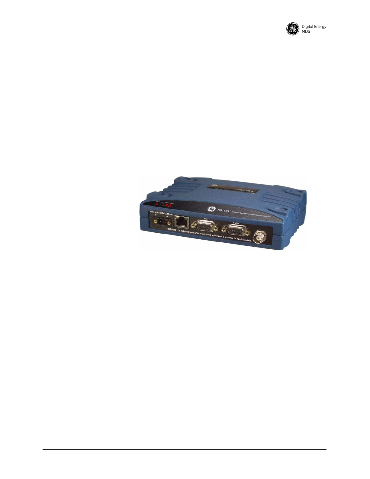
This manual is one of two publications for users of the MDS SD Series
Transceiver shown in Figure 1. It contains an overview of common
applications, installation planning data, specifications, troubleshooting,
and instructions for using the web-based Device Manager. This manual
is intended for technical personnel who perform network design, configuration, and troubleshooting of the equipment.
A companion Setup Guide is also available (Part no. 05-4847A01). The
scope of the Setup Guide is limited to installing the transceiver and
placing it in service for the first time. All product documentation may be
downloaded free of charge from the GE MDS website at
www.gemds.com. The website also contains links to Application Bulletins
and other product information.
Invisible place holder
Software & Device Manager Notations
Model Number Notations
Figure 1. MDS SD Series Transceiver
1.1 Conventions Used in This Manual
This product is designed for software control via a connected PC. To
show the names of screen items, keyboard entries, or other information
displayed on a PC, a distinctive bolded font is used throughout the
manual that appears as follows:
Bolded font example (for screen names and keyboard entr ies)
To show the navigation path leading to a particular screen, this same
font is used with forward-pointing arrows between screen names. For
example, suppose you wish to access the radio’s
The navigation string shown for it would appear as follows:
Configuration>>Packet Settings
The term “SD” or “SD Series” is used in this manual to denote all
models in the SD product line. Specific model numbers such as MDS
SD1 (150-174 MHz), SD2 (216-235 MHz), SD4 (300-512 MHz), and
SD9 (928-960 MHz) are used only when necessary to reference
model-specific features.
Packet Settings Screen.
MDS 05-4846A01, Rev. G SD Series Technical Manual 1
Page 10

Authorization Features
Some features of the radio are dependent on purchased options and
applicable regulatory constraints. A “key” icon is shown near the
heading of any such features. In some cases a feature upgrade may be
available. Contact your sales representative for additional information.
2 SD Series Technical Manual MDS 05-4846A01, Rev. G
Page 11
2.0 PRODUCT DESCRIPTION
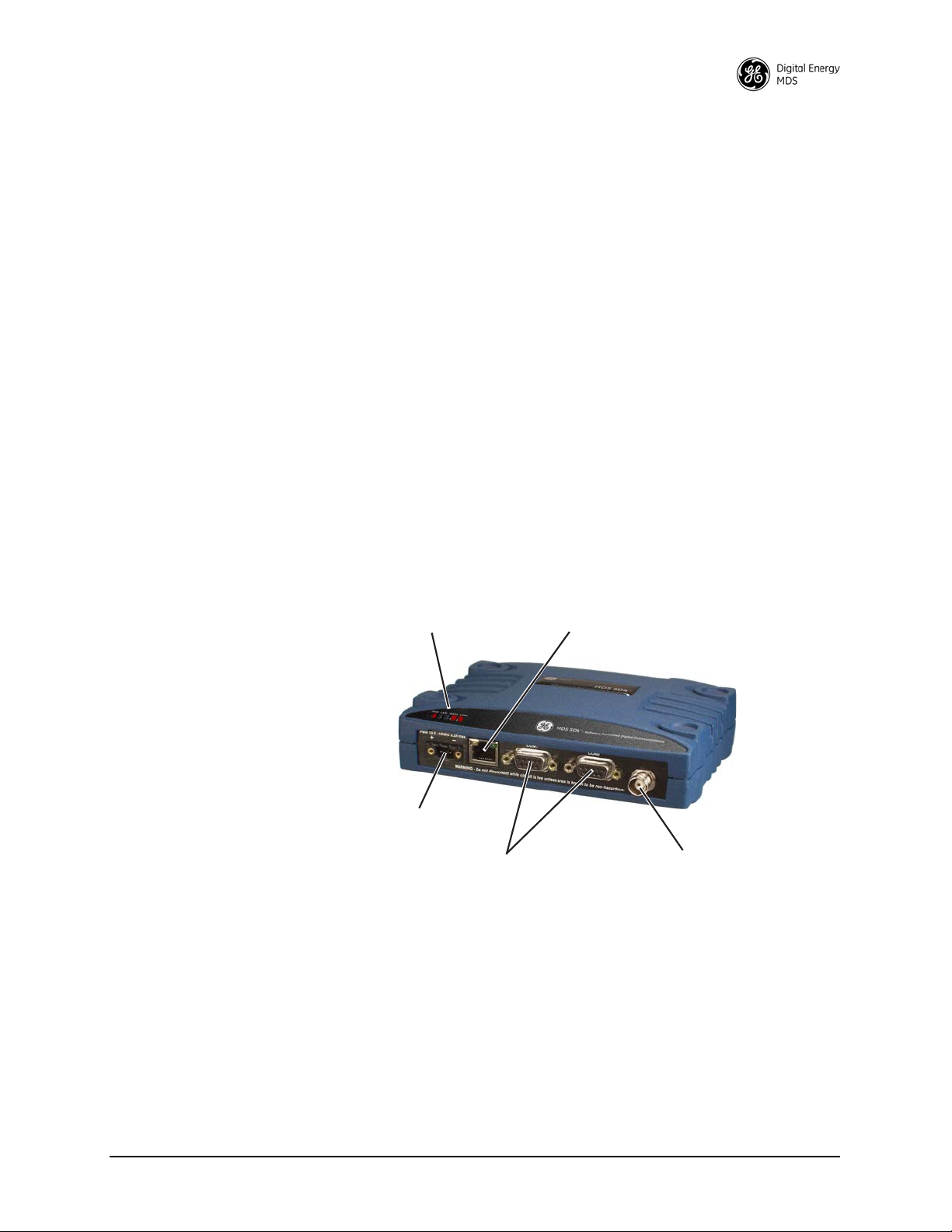
ANTENNA
CONNECTOR (TNC)
SERIAL DATA
CONNECTORS (DB-9)
DC INPUT
POWER
LED INDICATOR
PANEL
ETHERNET
CONNECTOR (RJ-45)
COM1 used for radio management
The transceiver is a software-configurable, industrial radio for use in
licensed data acquisition networks. It may be interfaced with a variety
of data control equipment including remote terminal units (RTUs), programmable logic controllers (PLCs), flow computers, and similar
devices. Data interface connections may be made for both serial
(RS-232/RS-485) and Ethernet protocols. It is designed for use in both
polled networks and report-by-exception (push) systems.
The radio employs digital signal processing (DSP) technology and a
fully digital transmit and receive IF chain to provide robust communications even under adverse conditions. DSP technology also helps eliminate the effects of component variations or temperature changes,
resulting in optimized performance.
2.1 Front Panel Connectors and Indicators
Figure 2 shows the transceiver’s front panel connectors and indicators.
These items are referenced in the installation steps and in various other
locations in the manual. The transceiver’s LED functions are described
in Table 10 on Page 31.
Invisible place holder
Figure 2. Front Panel Connectors & Indicators
MDS 05-4846A01, Rev. G SD Series Technical Manual 3
Page 12

2.2 Key Product Features
The transceiver is designed to meet the demanding needs of today’s
wireless networks in a compact, and rugged package. It offers an array
of features in a single hardware platform:
• Software-configurable via a built-in Device Manager—no manual controls or adjustments.
• Media Access Control (MAC) to prevent data collisions when two
or more radios try to use the radio channel at the same time.
• Available encryption of payload data (AES 128-bit)
• Supports Virtual LAN (VLAN) operation
• Terminal Server capability to enable IP addressing of serial
interface ports on individual radios
• Store and Forward capability
• Supports a wide variety of modem speeds and bandwidths for regulatory compliance in virtually all regions of the world
• Ethernet & serial interfaces—ideal for migration to IP networks
• Dual serial functionality (RS-232 and RS-485)
• Over-the-air reprogramming of remote units—no unnecessary
trips to radio sites
• Licensed 5-watt design, maximizes communications range with
low interference risk from other users
• Configurable via software as a Remote or a Master unit
• Low power “sleep mode”—ideal for battery-powered solar sites
• Virtual Radio Channels (VRC) support multiple polling applications on one radio
NOTE: Some features may not be available on all units, depending on the
options purchased and regulatory constraints for the region in which
the radio will operate.
Media Access Control (MAC)
An important feature of the transceiver is Media Access Control (MAC).
The radio’s MAC is specifically designed for use with narrow bandwidth, half duplex radio networks such as those commonly used in
licensed telemetry systems. When the MAC is enabled, it provides efficient support of multiple data traffic models including multiple hosts,
synchronous and asynchronous polls, and report-by-exception (push
traffic). MAC ensures that every transceiver in the network has an equal
probability of gaining access to the radio channel when it has data to
send.
Coordination of Channel Access
The main objective of the MAC is to coordinate channel access for all
radios in the network, preventing data “collisions” that can occur with
simultaneous transmissions from radios on the same RF channel. With
MAC operation a single radio is configured as an Access Point (AP) and
other units are designated as Remotes. The AP serves as the controller
4 SD Series Technical Manual MDS 05-4846A01, Rev. G
Page 13

of the RF network. Remotes request permission from the AP to use the
RF channel before sending payload data, thus avoiding collisions of
data, and creating a highly reliable wireless network. The MAC is
responsible for allocating which unit gets access to the broadcast
medium (the RF channel), when, and for how long.
Data Validation Additionally, the MAC validates all messages and purges corrupted data
from the system. Successful delivery of data is ensured through the use
of retries and acknowledgements. Minimal overhead is used to accomplish these tasks, which translates to increased bandwidth efficiency of
the radio channel with minimal latency, ensuring that messages are
delivered in a timely manner.
VLAN Capability
A Virtual Local Area Network (VLAN) is essentially a limited broadcast domain, meaning that all members of a VLAN receive broadcast
frames sent by members of the same network, but not frames sent by
members of a different network.
The radio supports port-based VLAN at the Ethernet interface and over
the air, according to the IEEE 802.1Q standard. When VLAN Mode is
enabled, the wireless ports of both AP and Remote radios act as a “trunk
port” to carry data.
Terminal Server Capability
The unit’s Terminal Server option allows serial port data to be sent over
the air in the form of IP packets. It works by encapsulating data from the
serial (
COM1/COM2) ports as IP packets, then transmitting it over the air.
At the receiving end, the data is decapsulated and delivered to the appropriate COM port. See “Terminal Server COM1/2 Configuration” on
Page 56 for more information.
Store and Forward Capability
Store and forward (SAF) capability is available in Packet w/MAC mode.
It allows a radio to store up incoming data, and retransmit it a short time
later to other stations. This can be used to link outlying remote stations
to the AP when direct communication is not possible due to terrain, distance, or other obstructions.
Communication routes are automatically discovered and traffic is intelligently filtered so that only store and forward traffic is sent through the
SAF unit, conserving critical bandwidth in your network.
MDS 05-4846A01, Rev. G SD Series Technical Manual 5
Page 14

2.3 SD Model Offerings
The radio is offered in three model types, using one hardware platform:
• Ethernet—All SD features and functionality
• Standard—All SD features, except over-the-air Ethernet data
• x710—Direct, drop-in compatibility for networks using a mix of
SD and older MDS x710 radios
Model Number Codes
Standard Modes (Modes covered by this manual)
The unit’s complete model number is printed on the bottom label. Additional unit details are available through the Device Manager, described
later in this manual.
2.4 Operating Modes and Applicable Manuals
In addition to the model offerings above, the radio may be configured to
operate in any of the following modes:
• Packet Mode—Payload data from the radio’s serial and Ethernet
ports is assembled into packets and transmitted over the air.
Packet mode supports Ethernet Bridging, AES 128-bit encryption, and Virtual Radio Channels (VRC). This mode requires an
all-SD radio network.
• Packet w/MAC—This mode is similar to Packet Mode above,
but adds a Media Access Control (MAC) layer to the feature set.
The MAC provides robust collision avoidance, with an AP controlling which unit can access the communication channel, and
when, for maximum efficiency of the radio channel. This mode
supports push traffic, data retry, and store and forward operation.
This mode requires an all-SD radio network.
• Transparent Mode—This mode is over-the-air compatible with
MDS x710 transceivers, while supporting payload data encapsulated in IP at the Ethernet port. This mode is ideal for mixed networks containing SD and older MDS x710 radios. It allows
currently deployed x710 networks to add support for Ethernet
data at either the master or remote radios. Note that Ethernet
Bridging is not supported in this mode.
x710 Mode: Different Manual Required
• x710 Mode—This mode provides direct, drop-in compatibility
with MDS x710 (4710 or 9710) transceivers, and uses the same
core command set as these radios. It is designed for use in systems
containing a mix of newer SD radios and legacy MDS x710 units.
IMPORTANT: This manual does not
cover x710 Mode operation. Refer instead to the following manuals for x710 instructions:
• Start-Up Guide (x710 Mode)— Part No. 05-4669A01
• Technical Manual (x710 Mode)—Part No. 05-4670A01
6 SD Series Technical Manual MDS 05-4846A01, Rev. G
Page 15
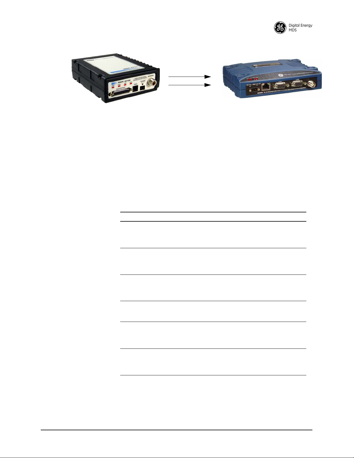
Invisible place holder
Figure 3. SD Transceivers offer compatibility with older MDS x710
Transceivers (left), and may be used for replacement and/or
interoperability in these networks. A retrofit kit is available for
connector conversion (see Table 1).
2.5 Accessories and Spares
Table 1 lists common accessories and spare items for the transceiver.
GE MDS also offers an Accessories Selection Guide listing additional
items that may be used with the product. Visit www.gemds.com or contact
your factory representative to obtain a copy of the guide.
Table 1. Accessories & Spare Items
Accessory Description Part Number
Retrofit Kit, Digital Contains adapters and connectors
Retrofit Kit, Analog Contains adapters and connectors
DC Power Plug,
2-pin, polarized
Setup Guide
(for Packet and
Transparent Modes)
Flat Mounting
Bracket Kit
DIN Rail Mounting
Bracket Kit
needed to facilitate the replacement
of an existing MDS x710A/C/M
digital transceiver.
needed to facilitate the replacement
of an existing MDS x710A/C/M
analog transceiver.
Mates with power connector on radio
case. Screw terminals provided for
wires, threaded locking screws to
prevent accidental disconnect.
Describes the installation and setup
of the transceiver. A companion to
this Technical Manual.
Brackets that attach to the bottom of
the unit. Used for mounting to a flat
mounting surface. Fits the mounting
footprint of MDS x710 transceivers.
Contains bracket for mounting the
transceiver to standard 35 mm DIN
rails commonly used in equipment
cabinets and panels.
03-4696A01
03-4697A01
73-1194A53
05-4847A01
03-4123A14
03-4125A04
Protected Network Station
The transceiver is available in a protected network configuration, known
as the SDxP (Figure 4), where x denotes the particular model of SD
transceiver installed inside the chassis (i.e., SD1, 2, 4, 9, etc.).
MDS 05-4846A01, Rev. G SD Series Technical Manual 7
Page 16
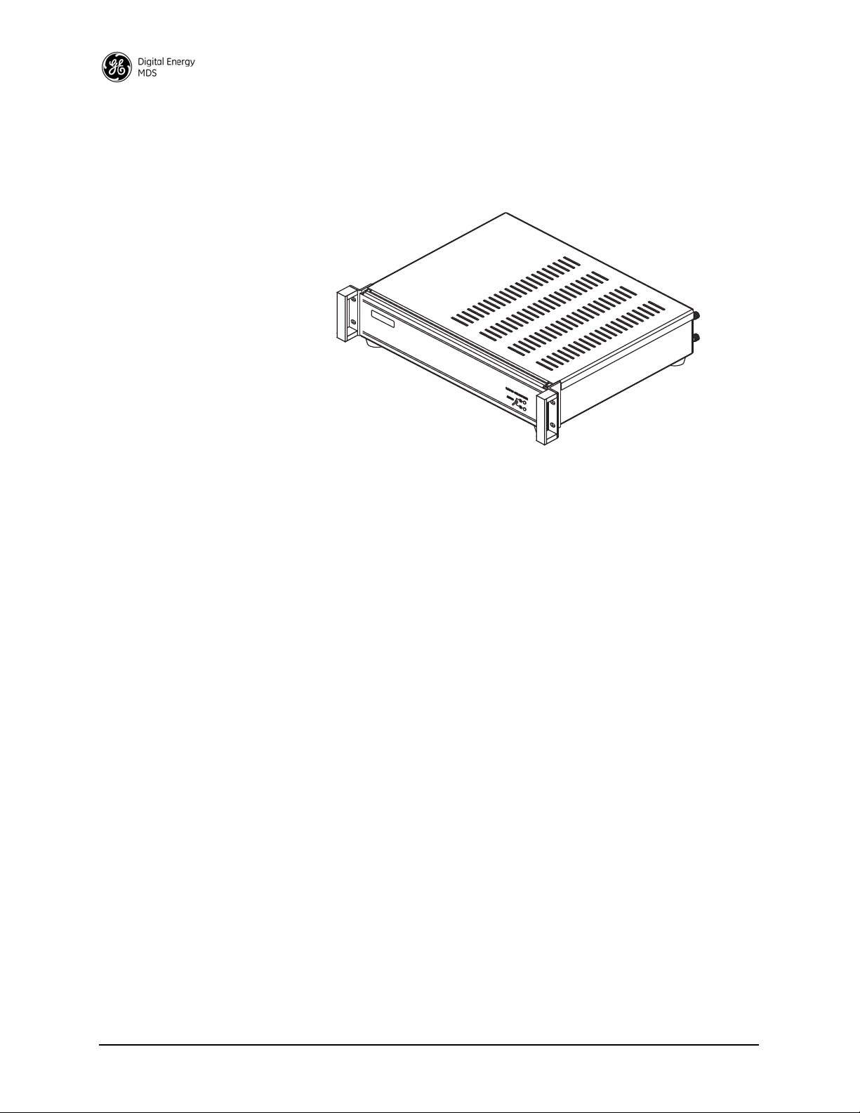
The SDxP is a tabletop or rack-mount unit designed to hold two transceivers, two power supplies, and a switchover logic board that automatically selects between transceiver A or B as the active unit. Manual
selection may also be made using a front panel switch.
Invisible place holder
Figure 4. Protected Network Station
With two transceivers and two power supplies installed, the unit continues to communicate even if a failure occurs in one of the transceivers,
or its associated power supply. This capability is important in critical
applications where uninterrupted service is required. Refer to publication 05-4161A01 for detailed information on this product.
SDxDT Configuration
Dual Protected Configurations
Two dual transceiver configurations are offered for the SD Series. They
are known as the SDxDT and the SDxDP. These configurations are used
for the following purposes:
• When full duplex operation is desired using dedicated Transmit
and Receive transceivers.
• When a Master or Repeater site requires bandpass duplexers due
to the presence of co-located antennas.
• When streaming Repeater operation is desired using dedicated
Transmit and Receive transceivers
The SDxDT uses the same chassis as the SDxP described above. However, one radio is configured with the transmit frequency and the other
for the receive frequency, with appropriate connections between them.
It also includes a bandpass duplexer tuned to a specific frequency for
simultaneous transmission and reception (full duplex) operation. Note
that the SDxDT provides one serial port and one Ethernet port for user
equipment.
8 SD Series Technical Manual MDS 05-4846A01, Rev. G
Page 17

SDxDP Configuration
The SDxDP is a protected, full duplex Master or Repeater site configuration. This consists of two SDxP chassis described earlier, with appropriate interconnect cabling between the units. The radios in one SDxP
are configured with the transmit frequency and the radios in the other are
configured with the receive frequency. The SDxDP also includes a
bandpass duplexer tuned to a specific frequency for simultaneous transmission and reception (full duplex) operation.
MDS 05-4846A01, Rev. G SD Series Technical Manual 9
Page 18

3.0 TYPICAL APPLICATIONS
This section describes common scenarios the transceiver may be used
in. A number of variations are possible; If you have unique requirements
not found here, it is recommended that you consult a support specialist
at GE MDS. Contact information is provided at the back of this manual.
3.1 Operating Parameters
The transceiver can operate in both poll-response and “push” communication/report-by-exception networks. In poll-response networks a central Master unit communicates with a number of Remote radios one at a
time. The Master exchanges data with the currently-connected Remote,
and when finished, it establishes a new connection with the next Remote
in the polling order. In push communication/Report by Exception networks, a Remote can also transmit if it has data to send, typically
prompted by a change in status conditions from connected data equipment.
The radio includes a number of parameters which may be set to suit the
requirements of a particular application. Table 2 provides a summary of
common applications, protocols, and radio modes used. Refer to the
table to determine what applications can be supported and the required
radio mode settings.
Table 2. Application Types vs. Key Radio Settings
Application
Polled Bridged Ethernet MODBUS TCP Packet w/MAC May also use Packet mode and enable LBT
Bridged Ethernet IP(ICMP/TCP/UDP/
Mixed Serial and Bridged
Ethernet
Report by Exception Serial and/or IP Packet w/MAC
Single Poll Multiple
Response
Two or more concurrent
serial polling applications
(COM2, COM1, and /or
IP Payload at master
Single Port Serial Polling
with encryption (COM2 or
COM1)
Single Port Serial Polling
without encryption
(COM2, COM1, or IP
Payload at master)
Protocol
(Example)
MODBUS TCP)
MODBUS RTU & IP Packet w/MAC May also use Packet mode with Multihost
Serial and/or IP Packet w/MAC
DNP3 and Modbus
RTU
Modbus RTU Packet AES On
Modbus RTU Transparent AES Off
Recommended
Radio Mode
Packet w/MAC May also use Packet mode and enable LBT
Packet w/MAC May also use Packet mode with Multihost
Notes
with Listen on RX.
with Listen on RX.
feature enabled.
feature enabled.
10 SD Series Technical Manual MDS 05-4846A01, Rev. G
Page 19
3.2 Example Systems
RTU
MASTER STATION
REMOTE RADIO
REMOTE RADIO
RTU
HOST SYSTEM
OR: SDA-Augmented
Master Station
RTU
REMOTE RADIO
RTU
REMOTE RADIO
The following sections describe common system arrangements for the
transceiver. Other variations are possible, and if you have questions
about a specific application not covered here, you may contact your factory representative using the information at the back of this guide. For
typical radio settings in these systems, refer to Table 2 on Page 10.
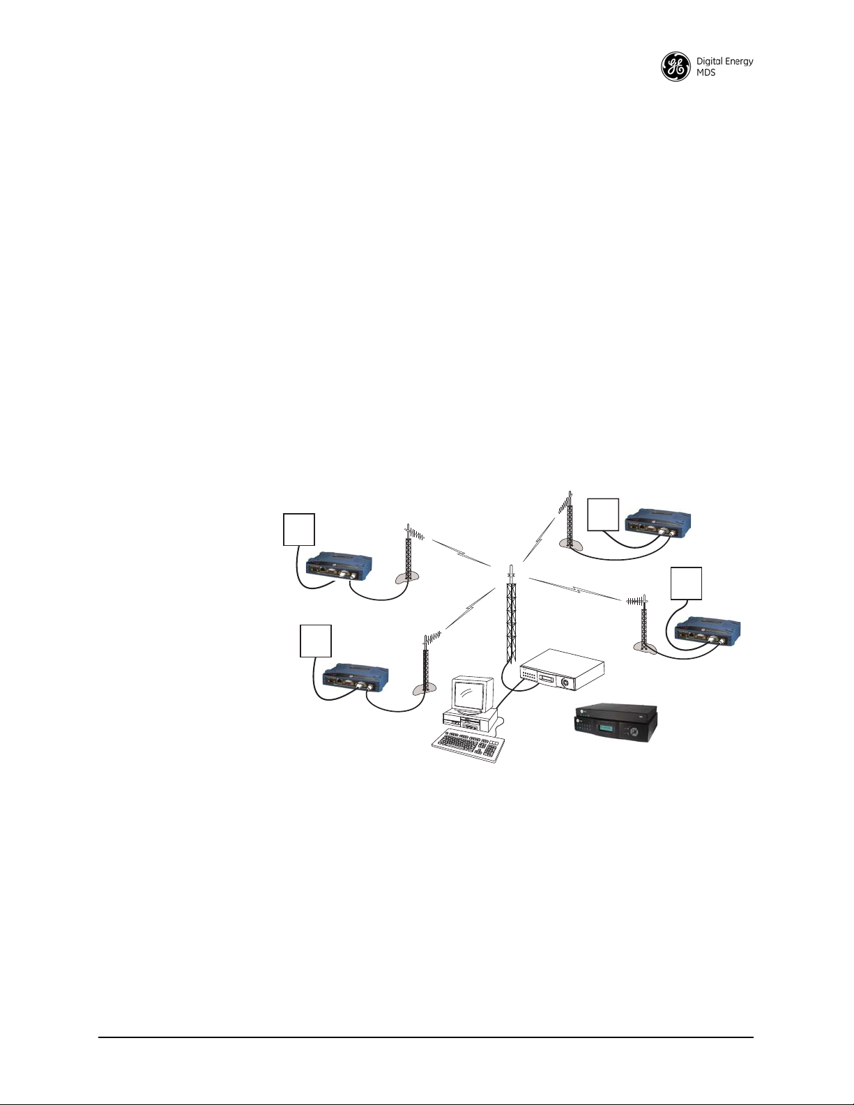
Multiple Address Systems (MAS)
This is a common application for the transceiver. It consists of a central
master unit and several associated remote units as shown in Figure 5. An
MAS network provides communication between a central host computer and remote terminal units (RTUs) or other data collection devices
in the field. Often, such a system is used to carry telemetry data to and
from widely separated remote radios.
Typical MAS applications may be for automatic, remote monitoring of
gas wells, water tank levels, electric power distribution systems, and
similar control and measurement functions.
Invisible place holder
Figure 5. Typical MAS Point-to-Multipoint Network
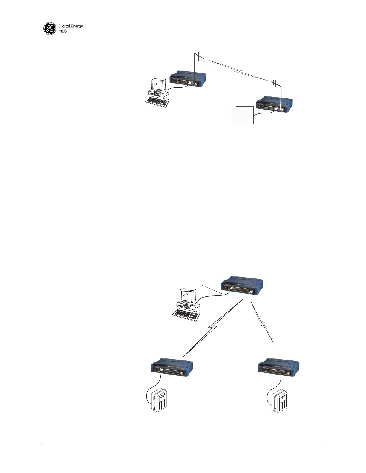
Point-to-Point System
Where permitted, the transceiver may also be used in a point-to-point
arrangement. A point-to-point system consists of just two radios—one
Master and one Remote (see Figure 6). It provides a simplex (or
half-duplex) communications link for the transfer of data between two
locations.
MDS 05-4846A01, Rev. G SD Series Technical Manual 11
Page 20
Invisible place holder
HOST
COMPUTER
REMOTE RADIO
MASTER RADIO
RTU
MASTER UNIT
To Ethernet Port
REMOTE RADIO
(One of several possible sites)
Ethernet
Serial RTU
(Terminal Server Connection)
REMOTE RADIO
(One of several possible sites)
Ethernet RTU
Ethernet
Serial
Figure 6. Typical Point-to-Point Link
IP/Ethernet Polling and Terminal Server Operation
Modern data/control networks often employ IP/Ethernet connectivity
throughout the system. The transceiver is well suited to provide connectivity between such sites using its RJ-45 modular connector on the front
panel and enabling Ethernet Bridging capabilities. Figure 7 shows an
overview of such a system.
Note that the Remote radio on the right side of the illustration uses a
serial connection. The radio’s Terminal Server feature allows direct
IP/addressing of serial ports on selected radios. See “Terminal Server
COM1/2 Configuration” on Page 56 for more details.
Figure 7. IP/Ethernet Polling Example
Invisible place holder
12 SD Series Technical Manual MDS 05-4846A01, Rev. G
Page 21

This type of network can also be used for general Ethernet bridging as
supported by the over-the-air bandwidth of the system. Bridge filters in
the radio may be set to reduce Ethernet traffic over the RF channel, and
improve performance.
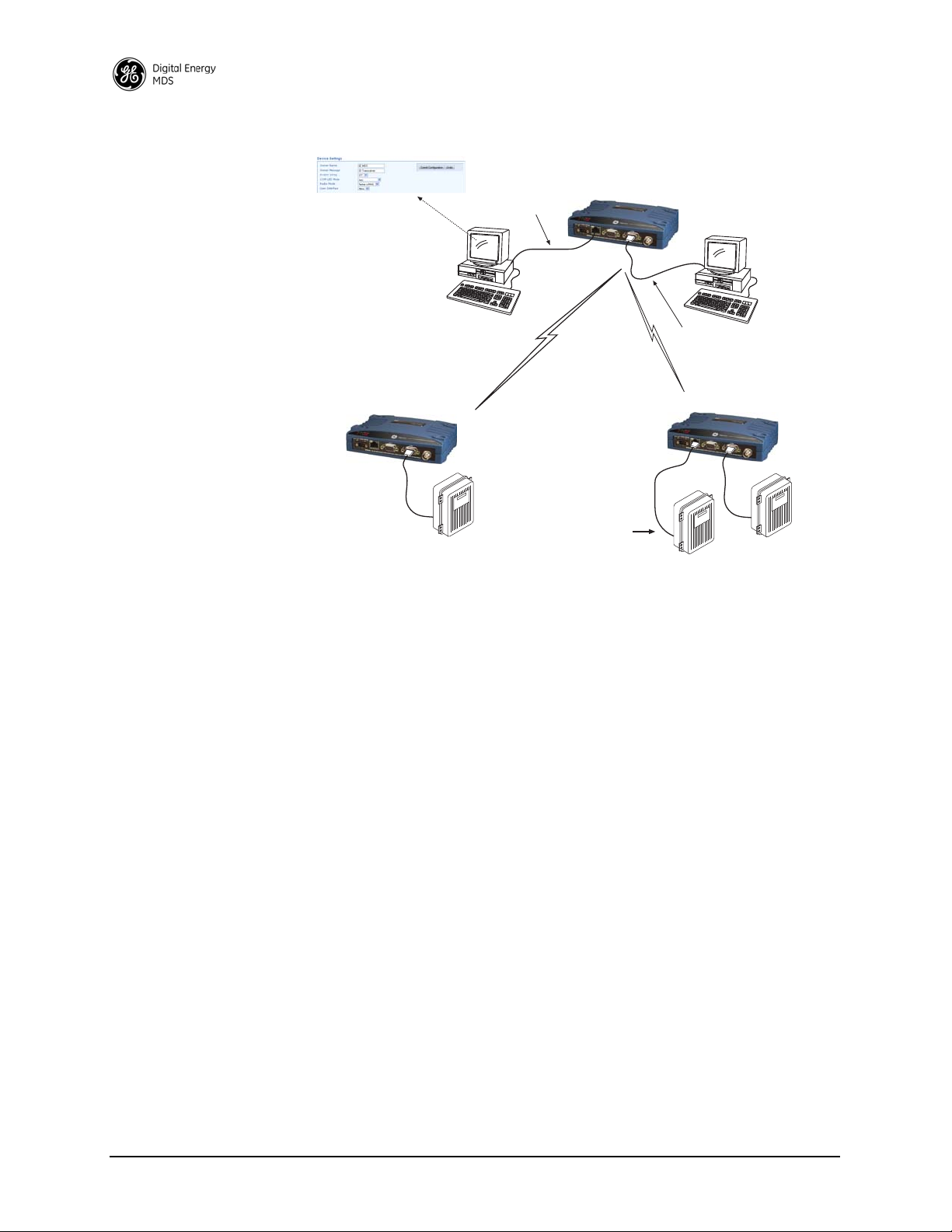
Port Sharing with Multiple Hosts
The transceiver allows for several external data networks to use the
same RF network without confusing the data streams. In such a system,
multiple host computers at the Master Unit poll their respective RTUs,
which may be alone or co-located at the Remote sites. Figure 8 shows
an example of such a system. In this case, two host computers (Host A
and Host B) are connected to the Master Unit via the applicable data
ports.
At the Remote sites, serial and Ethernet-based RTUs are employed, and
responding to a specific host computer. In the case of the Remote shown
on the lower right side of the figure, two RTUs are co-located, but
responding to different host computers and handling entirely different
data streams.
The radio eliminates the need for an external adapter or special external
configuration and handshaking when multiple host systems are connected to the network. The radio automatically controls access to the RF
channel by multiple hosts when Packet w/MAC is activated. Virtual
Radio Channels (VRCs) are used to separate serial data streams on
COM2, COM1, or IP payload ports. Packet With MAC operation provides Media Access Control. It is the recommended method of operation
for port sharing systems.
NOTE: An option exists to operate in Packet mode without MAC.
However, this Packet mode option should only be used for
systems that use legacy methods of collision avoidance
including Multihost and Listen Before Transmit (LBT). The
mode Packet with MAC provides superior performance and
better network reliability, collision avoidance and better
overall throughput. See corresponding sections of this manual
for more information on Packet mode options.
MDS 05-4846A01, Rev. G SD Series Technical Manual 13
Page 22
MASTER RADIO
HOST COMPUTER
(Host A)
To Ethernet Port
REMOTE RADIO
(One of several possible sites)
Radio Mode: Packet w/MAC
Ethernet
HOST C
HOST COMPUTER
(Host B)
Device Settings Screen
Serial
To COM2
Serial Port
Ethernet RTU Responding to
Host A
Serial RTU Responding to
Host B
Ethernet
REMOTE RADIO
(One of several possible sites)
Serial RTU Responding to
Host B
Co-located RTUs
Responding to
Different Hosts
Figure 8. Multihost Arrangement Using Packet w/MAC Mode
Push Communication (Report-by Exception)
Push Communication, sometimes referred to as Report-by-Exception
(RBE), differs from polled response in that a remote radio normally
transmits only when it has data to send. It does not depend on polling
from a master radio to initiate transmission. Some typical characteristics
of push communication systems are as follows:
• Remotes transmit asynchronously
• May contain large amounts of data
• Buffering and flow control are used
DNP3 and IEC 104 are examples of protocols that implement push communication. Note that both the serial and Ethernet versions of DNP3
support push communication.
IP Polling of Serial Remotes
The transceiver is ideal for use in systems employing a mix of serial and
Ethernet protocols. While many variations are possible, Figure 9 shows
a typical arrangement with an Ethernet host at the Master Unit that is
polling serial-based RTUs at Remote sites.
14 SD Series Technical Manual MDS 05-4846A01, Rev. G
Page 23
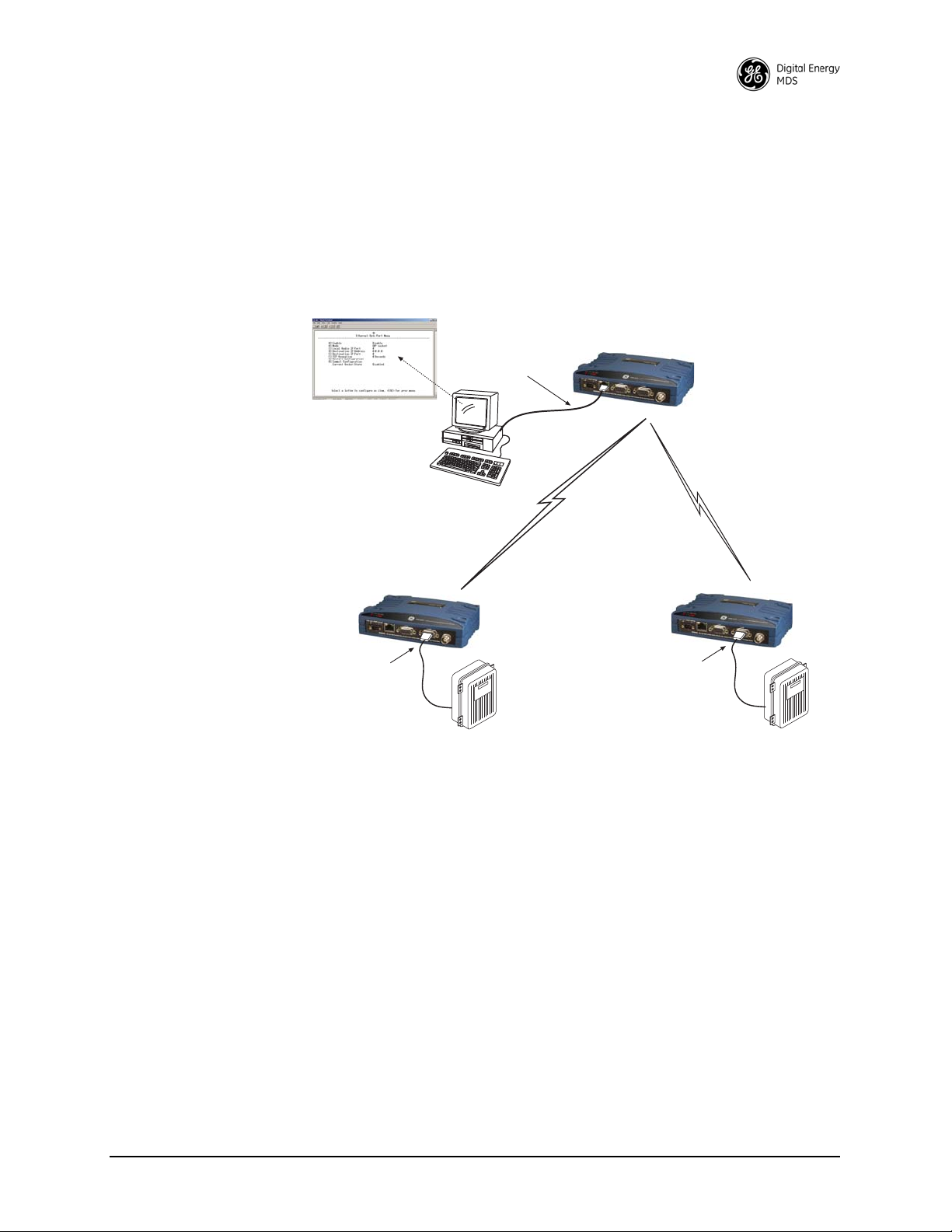
In this example, the Host Computer is connected directly to the radio’s
MASTER RADIO
(TCP Client)
HOST COMPUTER
(TCP Server)
REMOTE RADIO
(One of several possible sites)
MODBUS® SERIAL RTU
To COM2
Serial Port
To Ethernet Port
REMOTE RADIO
(One of several possible sites)
To COM2
Serial Port
Ethernet Data Port Menu
MODBUS RTU
Protocol
MODBUS® SERIAL RTU
Ethernet port, and the RTUs at the Remote sites are connected to the
transceiver via the radio’s COM2 serial data ports. The IP Payload feature, used at the Master, efficiently passes TCP payload over the air, and
eliminates the need for an external terminal server. (COM1 may also be
used for payload data if properly configured via the menu system. See
next example.)
Invisible place holder
MDS 05-4846A01, Rev. G SD Series Technical Manual 15
Figure 9. IP Polling of Serial Remotes
Serial Remotes with Two Serial Ports
In some cases, it is necessary to poll more than one RTU at a Remote
site. Figure 10 shows an example of such a system. Here, two RTUs are
connected to each Remote transceiver, both using the radio’s serial
ports—COM1 and COM2.
By default, the radio’s
COM1 port is configured for serial management
functions with a connected PC, but it may be configured for data service
using the menu system. This arrangement allows two telemetry networks to share a single radio system.
Page 24
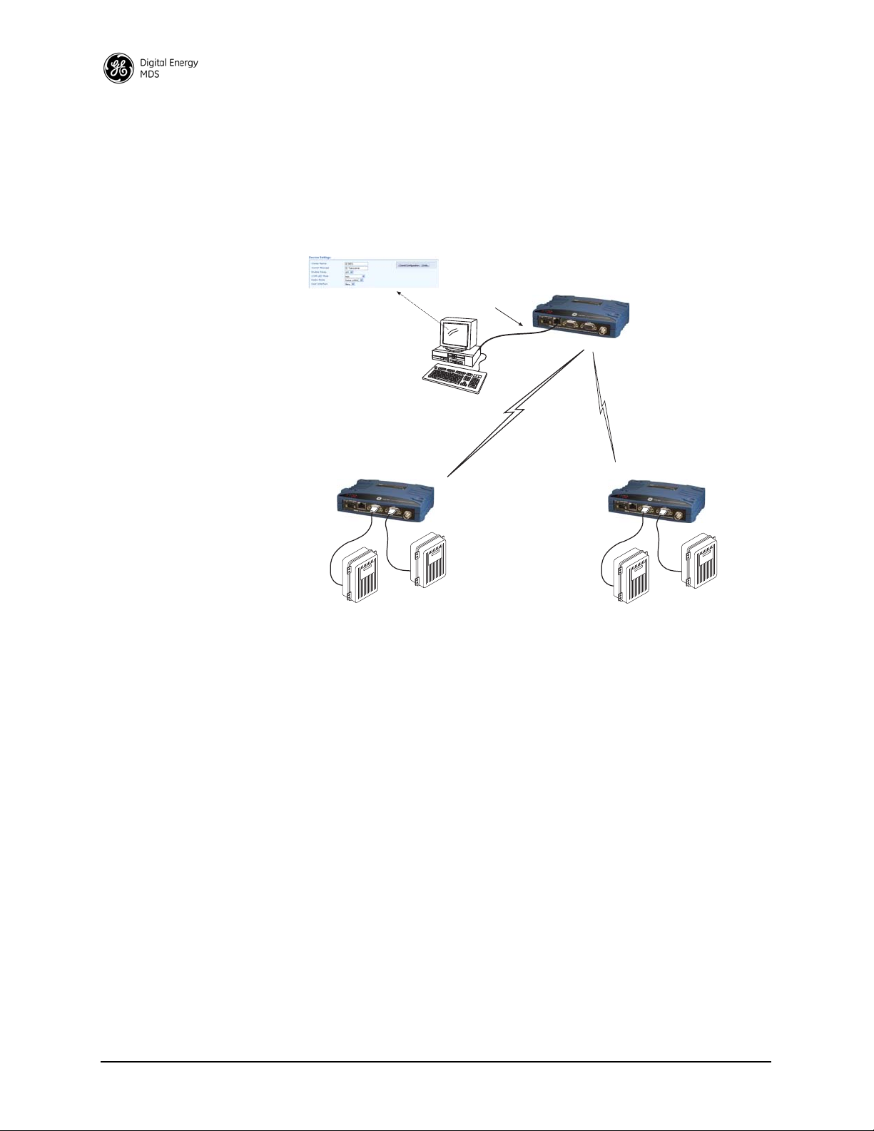
Packet w/MAC is the recommended method of operation when both
MASTER RADIO
HOST COMPUTER
(Host A)
To Ethernet Port
REMOTE RADIO
(One of several possible sites)
TCP Ethernet
REMOTE RADIO
(One of several possible sites)
SERIAL RTU
SERIAL RTU
SERIAL RTU
SERIAL RTU
Radio Mode: Packet w/MAC
Device Settings Screen
serial ports are used to pass payload data if there are two hosts (e.g., Port
Sharing with multiple host case). If there is a single host polling all units,
packet or transparent mode is the preferred option (depending on
whether encryption is required or not) even if there are two RTUs connected to a Remote radio.
Figure 10. Serial Remotes with Two Serial Ports
16 SD Series Technical Manual MDS 05-4846A01, Rev. G
Page 25
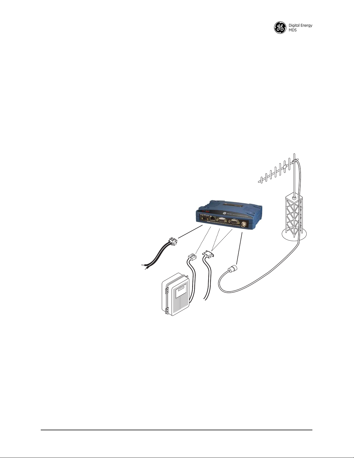
4.0 INSTALLATION PLANNING
TRANSCEIVER
LOW-LOSS FEEDLINE
ANTENNA SYSTEM
ETHERNET
SERIAL
Master Stations typically use
omni-directional antenna
POWER SUPPLY
10–30 VDC @ 2.5A
Negative Ground Only
DATA TELEMETRY DEVICE
OR HOST COMPUTER
OR:
This section covers pre-installation factors that should be considered when
installing the transceiver in the field. Careful planning will help achieve
optimal performance from the transceiver. After reviewing this section, refer
to the step-by-step installation procedures beginning on Page 26.
Figure 11 shows a typical station arrangement. The specific details at an installation site may vary, but there are three main requirements for installing the
transceiver in all cases:
• Adequate and stable primary power
• An efficient and properly installed antenna system
• Correct interface connections between the transceiver and the data
device.
MDS 05-4846A01, Rev. G SD Series Technical Manual 17
Figure 11. Typical Station Arrangement (Remote shown)
Page 26
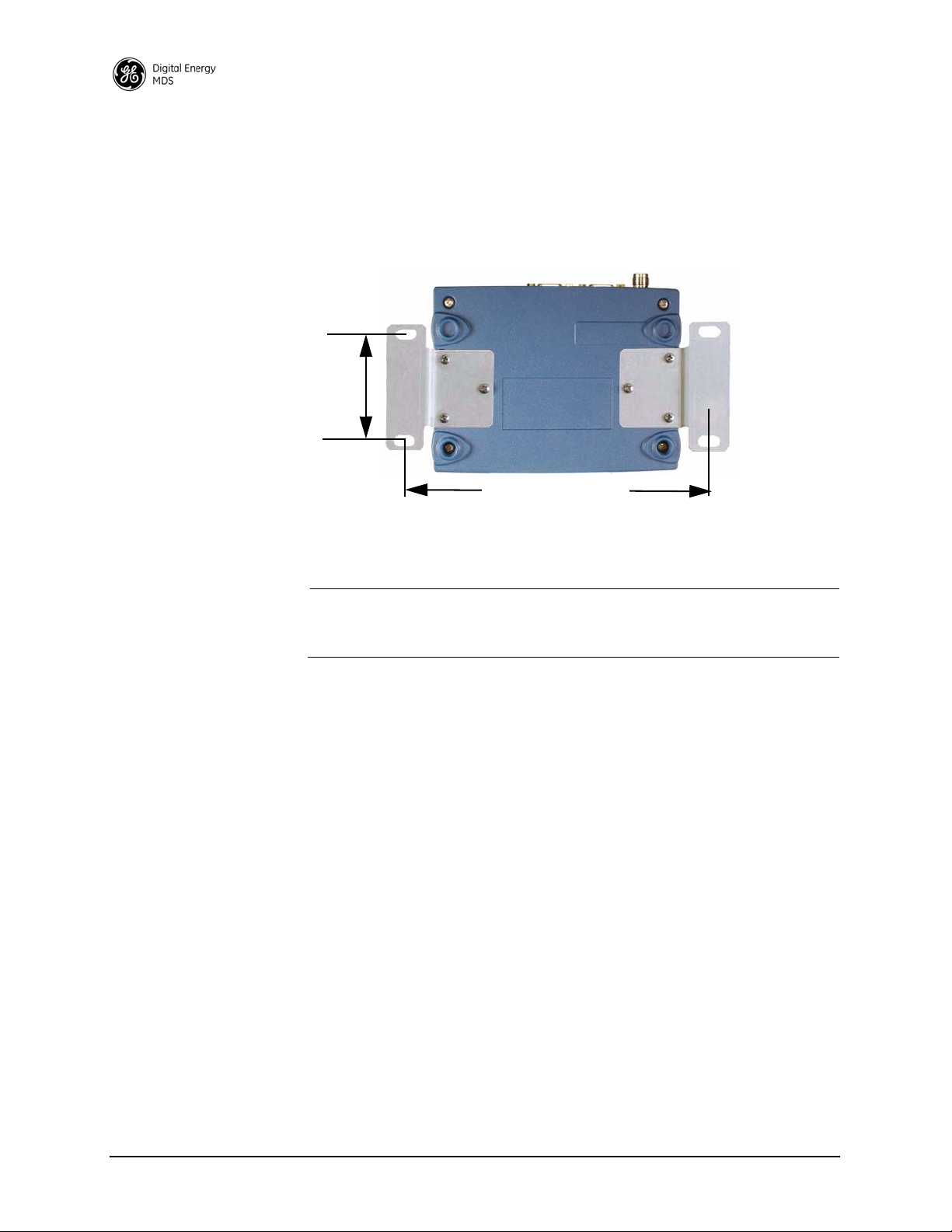
4.1 Mounting Options
6.675˝ (16.95 cm)
2.75˝ (7 cm)
The transceiver is normally provided with flat mounting brackets
attached to the bottom of the radio as shown in Figure 12. An optional
35mm DIN rail mounting bracket is also available, and is described
below.
Invisible place holder
Figure 12. Mounting Bracket Dimensions
NOTE: To prevent moisture from entering the radio, do not mount the case
with the cable connectors pointing up. Also, dress all cables to
prevent moisture from running along the cables and into the radio.
Optional DIN Rail Mounting
The unit may be mounted with an optional 35 mm DIN Rail Mounting
Bracket Kit (Part No. 03-4125A04). Equipment cabinets and racks of
modern design often employ this type of mounting. Once the DIN
bracket is attached to the radio, it allows for quick installation and
removal of the radio from its mounting rail without the need for tools.
The DIN Rail bracket attaches to the unit’s case as shown in Figure 13.
The entire assembly then attaches to the mounting rail.
18 SD Series Technical Manual MDS 05-4846A01, Rev. G
Page 27
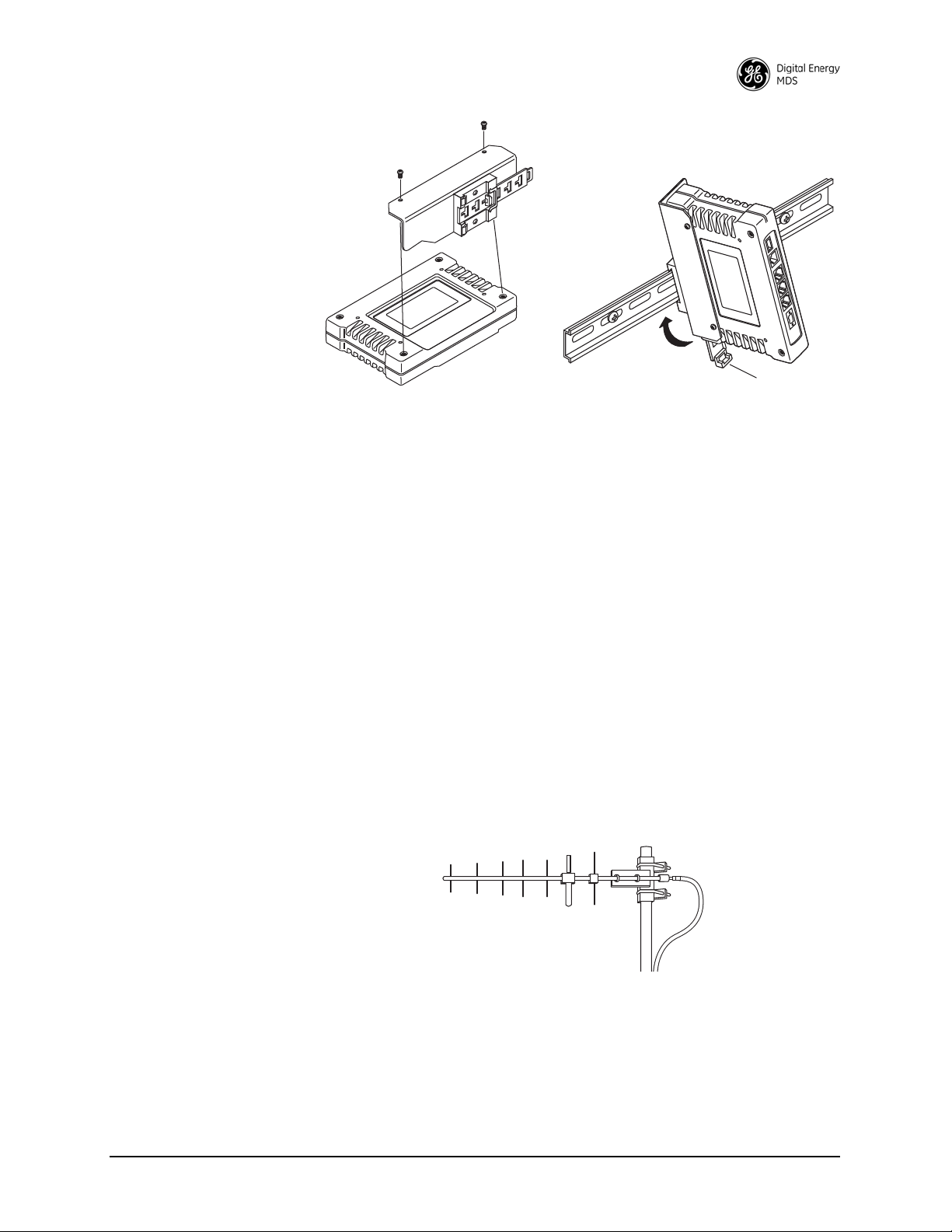
Figure 13. Attachment & Mounting of DIN Rail Bracket
Step 1: Attach the bracket using the
Step 2: Clip the assembly onto the
DIN Rail. Removal is performed by
pulling down on the Release Tab.
Release T ab
two screws provided. (Attach to
the end opposite the unit’s connectors.)
(Unit shown is for example only, and is not an SD Transceiver.)
4.2 Antennas and Feedlines
Antennas
The transceiver may be used with a number of different antennas. The
exact style and gain factor depend on the physical size and layout of
your system. Connection is made to the radio via a TNC coaxial connector.
A directional Yagi (Figure 14) or corner reflector antenna is generally
used at remote sites to minimize interference to and from other users.
Antennas of this type are available from several manufacturers,
including GE MDS. Contact your factory representative for details.
Invisible place holder
MDS 05-4846A01, Rev. G SD Series Technical Manual 19
Figure 14. Typical Yagi Antenna (mounted to mast)
Feedlines
The selection of an antenna feedline is very important. Poor quality
cable should be avoided as it will result in power losses that may reduce
the range and reliability of the radio system.
Page 28

The three tables below show the approximate losses that will occur
when using various lengths and types of coaxial cable in the 200, 400
and 960 MHz bands, respectively. Regardless of the type used, the cable
should be kept as short as possible to minimize signal loss.
Table 3. Signal Loss in Coaxial Cables (at 200 MHz)
10 Feet
Cable Type
RG-8A/U 0.26dB 1.27 dB 2.5 dB 5.07 dB
1/2 inch HELIAX
7/8 inch HELIAX
1-1/4 inch HELIAX
1-5/8 inch HELIAX
(3 Meters)
0.06 dB 0.38 dB 0.76 dB 1.6 dB
0.04 dB 0.21 dB 0.42 dB 0.83 dB
0.03 dB 0.16 dB 0.31 dB 0.62 dB
0.025 dB 0.13 dB 0.26 dB 0.52 dB
50 Feet
(15 Meters)
100 Feet
(30.5 Meters)
200 Feet
(61 Meters)
Table 4. Signal Loss in Coaxial Cables (at 400 MHz)
10 Feet
Cable Type
RG-8A/U 0.51dB 2.53 dB 5.07 dB 10.14 dB
1/2 inch HELIAX
7/8 inch HELIAX
1-1/4 inch HELIAX
1-5/8 inch HELIAX
(3 Meters)
0.12 dB 0.76 dB 1.51 dB 3.02 dB
0.08 dB 0.42 dB 0.83 dB 1.66 dB
0.06 dB 0.31 dB 0.62 dB 1.24 dB
0.05 dB 0.26 dB 0.52 dB 1.04 dB
50 Feet
(15 Meters)
100 Feet
(30.5 Meters)
200 Feet
(61 Meters)
Table 5. Length vs. Loss in Coaxial Cables (at 900 MHz)
10 Feet
Cable Type
RG-8A/U 0.85 dB 4.27 dB 8.54 dB 17.08 dB
1/2 inch HELIAX
7/8 inch HELIAX
1-1/4 inch HELIAX
1-5/8 inch HELIAX
(3.05 Meters)
0.23 dB 1.15 dB 2.29 dB 4.58 dB
0.13 dB 0.64 dB 1.28 dB 2.56 dB
0.10 dB 0.48 dB 0.95 dB 1.90 dB
0.08 dB 0.40 dB 0.80 dB 1.60 dB
50 Feet
(15.24 Meters)
100 Feet
(30.48 Meters)
200 Feet
(61 Meters)
4.3 DC Power Connection
The transceiver may be operated from any well-filtered 10.0 to 30 Vdc
power source. The supply must be capable of providing at least 2.5
Amperes continuously.
NOTE: Early SD4 models supported 10.5 to 16 Vdc power, not 10 to
30 Vdc. Always check the labeling above the power connector
to confirm the operating range for your unit.
20 SD Series Technical Manual MDS 05-4846A01, Rev. G
Page 29

A power connector with screw terminals is provided with each unit (see
Lead
Screws (2)
Binding
Wire Ports (2)
(Polarity: Left +, Right –)
Retaining
Screws (2)
Figure 15). Strip the wire leads to 6 mm (1/4 inch) and insert in the wire
ports, tightening securely. Be sure to observe proper polarity as shown
in Figure 15.
Invisible place holder
Figure 15. DC Power Connector (P/N 73-1194A39)
NOTE: The radio is designed for use in negative ground systems only.
4.4 Grounding Considerations
To minimize the chance of damage to the transceiver and connected
equipment, a safety ground (NEC Class 2 compliant) is recommended
which bonds the antenna system, transceiver, power supply, and connected data equipment to a single-point ground, keeping all ground leads
as short as possible.
Normally, the transceiver is adequately grounded if the supplied flat
mounting brackets are used to mount the radio to a well-grounded metal
surface. If the transceiver is not mounted to a grounded surface, it is recommended that a safety ground wire be attached to one of the mounting
brackets or a screw on the transceiver’s case.
The use of a lightning protector is recommended where the antenna
cable enters the building; Bond the protector to the tower ground, if possible. All grounds and cabling must comply with applicable codes and
regulations.
4.5 Ethernet Data Interface (RJ-45)
The transceiver’s Ethernet Port is used to connect the unit to another
Ethernet device. The port has built-in MDIX (auto-sensing) capability,
allowing either a straight-through or crossover cable to be used.
Figure 16 and Table 6 show pinout data for the Ethernet port. The
Ethernet interface supports both radio management and payload data
transport functions.
For radio management, connecting via a web browser provides
enhanced functionality and ease-of-use over serial (COM1) methods or
Telnet. Web-based management is the preferred and primary means of
accessing the transceiver through the built-in Device Manager.
MDS 05-4846A01, Rev. G SD Series Technical Manual 21
Page 30

Telnet may also be used on this connector, and provides the same
8
1234
56
7
menu-based user interface available via COM1. If you wish to use Telnet
for radio control, refer to the SD Serial/Telnet Management Supplement,
Part No. 05-6193A01.
Various options are available for passing Ethernet data on this connector, allowing system administrators to optimize the configuration for
maximum narrowband efficiency, based on the operating characteristics
of their system.
Figure 16. Ethernet Port (RJ-45) Pinout
(As viewed from the outside of the unit)
Table 6. Ethernet Port (IP/Ethernet) Pinouts
Pin Functions Ref.
1 Transmit Data (TX) High
2 Transmit Data (TX) Low
3 Receive Data (RX) High
4 Unused
5 Unused
6 Receive Data (RX) Low
7 Unused
8 Unused
4.6 Serial Data Interfaces
COM1 and COM2 on the front panel serve as the serial interface ports for
radio management and payload data, respectively. The following sections identify the pin functions used on each interface. These ports are
user-configurable for specific applications. The procedures for changing
their default operation are provided later in this guide.
NOTE: Not all PCs have a serial port. If one is not available, a
USB-to-Serial adapter and appropriate driver software may be
used to provide serial connectivity. These adapters are available from several manufacturers, including GE MDS.
COM1 (Serial) Connection
The default factory settings for the radio’s
assigns it for management or diagnostics of the radio via a serial connection to a PC. COM1 may be used to set basic parameters such as output
power, modem type and operating frequency of the radio, using text
commands.
22 SD Series Technical Manual MDS 05-4846A01, Rev. G
COM1 port (Figure 17)
Page 31

COM1 management provides an alternative to the web-based SD Device
5
96
1
RXD
TXD
GND
2
3
5
RXD
TXD
GND
2
3
5
>
<
DB-9 FEMALE
(COMPUTER)
DB-9 MALE
(RADIO SIDE)
Manager, accessible via the Ethernet RJ-45 port (see Page 21) when
Ethernet connectivity is not available. If you wish to use serial or Telnet
control, refer to the SD Serial/Telnet Management Supplement, Part No.
05-6193A01.
Figure 17. COM1 Connector (DB-9F)
As viewed from outside the unit
For typical applications, a straight-through DB-9 cable may be used for
PC management on COM1. If desired, a cable may be constructed as
shown in Figure 18, using Pins 2 (RXD), 3 (TXD), and 5 (Ground).
Table 7 lists all COM1 pins.
Figure 18. COM1 Wiring for PC Management
Table 7. COM1 Pin Descriptions
Pin
Number
1 -- No function
2OUTRXD (Received Data)—Supplies received data to the
3INTXD (Transmitted Data)—Accepts TX data from the
4 -- No function
5--Ground—Connects to ground (negative supply potential) on
6 -- No function
7 -- No function in most applications—User I/O for special
8 --- No function
9 -- No function in most applications—User I/O for special
Radio
Input/
Output
Pin Description
connected device.
connected device.
chassis.
applications
applications
MDS 05-4846A01, Rev. G SD Series Technical Manual 23
Page 32

COM2 (Data) Connections
5
96
1
Typically, the COM2 port (Figure 19) is used for connecting the radio to
an external DTE serial device supporting the RS-232 or RS-485 serial
data format. The radio supports serial data rates of 300, 1200, 2400,
4800, 9600, 19200, 38400, 57600, and 115200 bps (asynchronous only).
Pin Descriptions— RS-232 and RS-485
Table 8 and Table 9 provide detailed pin descriptions for the COM2 data
in RS-232 mode and RS-485 modes, respectively.
port
NOTE: In addition to RS-485 mode, the radio is capable of operating
in RS-422 mode. RS-485 must be selected in the menu, and the
pin descriptions/wiring arrangements shown in Table 9 apply.
Figure 19. COM2 Connector (DB-9F)
As viewed from outside the radio
NOTE: The radio is hard-wired as a DCE device.
Table 8. COM2 Pin Descriptions—Radio in RS-232 Mode
Pin
Number
Radio
Input/
Output
1OUTDCD (Data Carrier Detect/Link)—A high indicates signal
2OUTRXD (Received Data)—Supplies received data to the
3INTXD (Transmitted Data)—Accepts TX data from the
4INSleep Mode Input—Grounding this pin places the radio in a
5--Signal Ground—Connects to ground (negative supply
6OUTAlarm Output (DSR)—Behavior is user-configurable. Default
7INRTS (Request-to-Send)—Keys the transmitter.
8OUTCTS (Clear-to-Send)—Goes “high” after the programmed
9 -- Reserved—User I/O for special applications
Pin Description
received.
connected device.
connected device.
low power consumption mode.
potential) on chassis.
behavior: An RS-232 high/space (+5.0 Vdc) on this pin
indicates an alarm condition. An RS-232 low/mark (–5.0 Vdc)
indicates normal operation.
CTS delay time has elapsed (DCE), or keys another
connected radio when RF data arrives (CTS KEY).
24 SD Series Technical Manual MDS 05-4846A01, Rev. G
Page 33

Table 9. COM2 Pin Descriptions—Radio in RS-485 Mode
EIA-485 2-WIRE CONNECTIONS
TXD +
RXD +
2
3
7
RADIO
DATA CONNECTOR
8
RXD –
TXD –
EIA-422 4-WIRE CONNECTIONS
RXD+/TXD+
2
3
7
RADIO
DATA CONNECTOR
8
RXD–/TXD–
EXTERNAL DEVICE
EXTERNAL DEVICE
RXD –
TXD +
RXD +
TXD –
RXD –
TXD +
RXD +
TXD –
This jumpering must be provided by user.
Pin
Number
Radio
Input/
Output
Pin Description
1OUTCarrier Detect/Link—A high indicates signal received.
2OUTTXD+/TXA (R eceived Data +)—Non-inverting driver output.
Supplies received payload data to the connected device.
3INRXD+/RXA (Transmitted Data +)— (Transmitted Data +).
Non-inverting receiver input. Accepts payload data from the
connected device.
4INSleep Mode Input—Grounding this pin places the radio in a
low power consumption mode.
5--Ground—Connects to ground (negative supply potential) on
the radio’s PC board.
6OUTAlarm Output—Behavior is user-configurable. Default
behavior: A high on this pin indicates an alarm condition; a low
indicates normal operation.
7INRXD-/RXB (Transmitted Data -)— Inverting receiver input
8OUTTXD-/TXB (Received Data -)—Inverting driver output.
9 -- Reserved—User I/O for special applications
COM2 PORT NOTES & WIRING ARRANGEMENTS:
• RXD+ / RXA and RXD– / RXB are data sent into the radio to be transmitted out
• RXD+ / RXA is positive with respect to RXD– / RXB when the line input is a “0”
• TXD+ / TXA and TXD– / TXB are data received by the radio and sent out
• TXD+ / TXA is positive with respect to the TXD– / TXB when the line output is a “0”
Invisible place holder
MDS 05-4846A01, Rev. G SD Series Technical Manual 25
Figure 20. RS-485 Wiring Arrangements
Page 34

5.0 STEP-BY-STEP INSTALLATION
In most cases, the steps given here are sufficient to install the transceiver. Refer to “INSTALLATION PLANNING” on Page 17 for additional details, as required.
1. Mount the transceiver. Attach the mounting brackets to the bottom
of the transceiver case (if not already done), using the four 6-32 x
1/4 inch (6 mm) screws supplied. Mounting bracket dimensions are
shown in Figure 12 on Page 18. Secure the brackets to a flat,
grounded surface. (If a grounded surface is not available, run a
separate ground wire to the transceiver—see “Grounding
Considerations” on Page 21.)
2. Install the antenna and feedline. The antenna used with the radio
must be designed to operate in the radio’s frequency band, and be
mounted in a location providing a clear path to the associated station(s). At Remote sites, aim directional antennas toward the master
unit. Low loss coaxial feedline should be used and it should be kept
as short as possible.
3. Connect the data equipment. Connection may be made using
IP/Ethernet signaling, Serial protocols (RS-232/RS-485), or both.
• If an Ethernet device is to be used, connect it to the front panel
ETHERNET port to the right of the PWR connector.
• If a serial device is to be used, connect it to COM2 on the front
panel. The radio is hardwired as a DCE device. A straight-through
cable may be used in most applications.
NOTE: Do not connect the radio’s Ethernet port to a LAN with high
traffic levels. Excessive traffic will overload the port and cause
it to be temporarily disabled. In general, traffic levels above 4
Mbps are likely to cause port shutdown. (Traffic limit is less
than 4 Mbps with packet sizes smaller than 64 bytes.)
4. Connect primary power. Input power must be within 10.0 to 30
Vdc and capable of providing at least 2.5 Amperes. (Note that some
older SD4 radios only allow a 10.5 to 16 Vdc range. Always verify
the voltage range by checking the label above the power input
socket.)
A power connector with screw-terminals is provided with the unit
(see Figure 15 on Page 21). Strip the wire leads to 1/4 inch (6 mm)
and insert them into the wire ports. Be sure to observe proper
polarity. Tighten the binding screws securely.
26 SD Series Technical Manual MDS 05-4846A01, Rev. G
Page 35

The unit is designed for use with negative-ground sys-
CAUTION
POSSIBLE
EQUIPMENT
DAMAGE
tems only . The power supply should be equipped with
overload protection (NEC Class 2 rating), to protect
against a short circuit between its output terminals
and the radio’s power connector.
5. Configure Basic Settings. Connect a PC to the radio’s Ethernet
connector. Access the radio’s Device Manager through the PC’s
browser. On a factory default radio, the Device Manager automatically starts the Basic Setup Wizard. The wizard steps you through
the essential radio settings in streamlined fashion. Detailed steps for
starting configuration of the radio are presented in Section 5.1
below.
5.1 Initial Configuration
This section describes setup of the radio for its first on-air operation. A
full description of operating settings is given in Section 6.0 on Page 34.
Web-Based Management
The Device Manager is the recommended method for user management.
It is a built-in software tool that works with your PC’s browser to provide an intuitive, web-style presentation of all radio information, settings, and diagnostics.
The Device Manager also contains a “wizard” function to assist in setting up a radio with a minimum of user actions. Web management uses
the radio’s ETHERNET RJ-45 connector. See “Web Browser Connection” on Page 28 for details.
NOTE: Web access must be enabled via the Device Security Screen
before using this feature. This is the default setting on a factory
supplied radio. If changes are needed, check/activate by
logging into the Device Security Screen. See your Network
Administrator for further assistance.
Alternative Management Methods
The following methods are for use where web-based management is not
available:
• Serial—(COM1 DB9 connector). This is the “console terminal”
method of control commonly used on earlier GE MDS radios.
• Telnet—(ETHERNET RJ-45 connector). Telnet offers essentially
the same capabilities as Serial control, but may be performed
either through a local connection, or over a network.
MDS 05-4846A01, Rev. G SD Series Technical Manual 27
Page 36

For more information on alternative management methods, refer to the
PC Running Web Browser
Transceiver
RJ-45 to Ethernet Port
SD Serial/Telnet Management Supplement, Part No. 05-6193A01, available from the GE MDS website at www.gemds.com.
Web Browser Connection
Requirements The remainder of this se ction describes connection and use of the radio’s
built-in Device Manager. To connect to the radio and manage it via the
Device Manager, you will need the following:
• A PC with a web browser program installed.
• An Ethernet cable connected between the PC and the radio as
shown in Figure 21. (Alternatively, a network connection may be
used, as long as the radio can be reached via its IP address.)
• The radio’s IP address. Check with your Network Administrator,
or determine the address via a serial/console connection (see
Starting Information Screen). The default address for a factory
supplied radio is 192.168.1.1.
• The user name and password for the radio. Check with your Network Administrator, or, if a username and password have not
been set, use the factory defaults of admin for both entries. (For
security, a new password should be established as soon as possible after login.)
Invisible place holder
Logging On
28 SD Series Technical Manual MDS 05-4846A01, Rev. G
Figure 21. PC Connection to Radio for Web Management
1. Connect the radio to a PC via an Ethernet connection.
2. Configure your PC network settings to an IP address on the same
subnet as the radio. The default subnet mask is
255.255.255.0.
3. Enter the radio’s IP address in a web browser window, just as you
would enter a website address. When the login screen appears
(Figure 1), enter the User Name and Password for the radio. The
default entries for a new radio are both admin. Click OK.
Page 37

Invisible place holder
Figure 1. Login Screen
Using the Basic Setup Wizard
4. The Basic Setup Wizard (Figure 22) begins automatically upon connection to a new factory shipped radio. It may also be started manually by selecting
Setup Wizards>>Basic Setup, and then clicking Start.
The Wizard displays a series of screens with key selections as follows:
• TX/RX Frequencies
• RF Output Power
•Radio Mode
• Modem Type
• Com 2 Port Baud Rate
• Bridge Mode
• Encryption Mode
• Device Type
NOTE: TX and RX frequencies may not be set when the radio is
shipped from the factory, depending on ordering options. If no
frequencies have been set, an alarm condition is generated and
the PWR LED flashes. These will be cleared after the frequencies are set. In all cases, users must verify that the frequencies
are properly set according to the station license.
NOTE: Operation on exact multiples of 25 MHz is not supported by
the SD4 transceiver (i.e., 400, 425, 450, 475, and 500 MHz).
Continue through each wizard screen until all selections have been
made. (You may back up to previous screens if required, to review or
change settings.) If you are unsure about a required setting, contact
your Network Administrator for assistance.
MDS 05-4846A01, Rev. G SD Series Technical Manual 29
Page 38

Invisible place holder
Figure 22. Basic Setup Wizard
5. At the conclusion of the wizard, click Done. Configuration is now
complete for the connected radio. Log out of the Device Manager by
clicking Logout in the upper right hand side of the screen. If desired,
you may proceed with the additional functions described below.
Using the Remote Management Wizard
Getting an Overview of Radio Settings
To program the key settings of other radios installed in the wireless network, select Setup Wizards>>Remote Management, and follow the prompts
contained in that tool. At the conclusion of the wizard, click Commit Con-
figuration
, followed by Done. Remote configuration is now complete.
To get a top-level view of the key settings and operating parameters for
the radio, select Overview and a summary screen will be displayed. When
finished, log out of the Device Manager by clicking
Logout in the upper
right hand side of the screen.
5.2 Initial Startup & Checkout
In-service operation of the transceiver is completely automatic. Once
the unit has been properly installed and configured as described above,
operator actions are limited to observing the front panel LED indicators
for proper operation.
If all parameters are correctly set, operation of the radio can be started
by following these steps:
1. Apply DC power. Unit must be powered on
2. Observe the LED status panel for proper indications (Table 10).
30 SD Series Technical Manual MDS 05-4846A01, Rev. G
Page 39

3. If not done earlier, refine the antenna heading of the station to maximize the received signal strength (RSSI) from the Master Unit. The
Maintenance & Status>>Performance screen may be used to observe
RSSI. Turn the antenna heading slowly so that the RSSI display can
be updated.
NOTE: The RSSI facility limits the maximum displayed signal
strength to –60 dBm.
Invisible place holder
Table 10. LED Status Indicators
LED Name Description
PWR • Continuous—Power applied, no problems detected.
• Rapid flash (5 times-per-second)—Alarm indication, or
RX/TX frequencies not set.
LAN • Flashing—Data is being transmitted and received.
• Off—Ethernet signals not detected
DATA 1/DATA2 These LEDs show data activity on the DB-9 serial payload
ports (COM1/COM2).
LINK When lit, indicates that a communication link exists with the
Master Unit.
Ethernet Connector LEDs
The 10/100 Base-T Ethernet connector has two embedded LEDs. A
flashing green indicator shows data activity, and a yellow indicates 100
Mbps operation has been achieved.
5.3 Optimizing the Radio Network
With basic configuration complete, there are several additional settings
that can be made to optimize the radio system. The settings below
should be reviewed and changed as necessary to suit your particular
application.
Modem Type Setting
All radios in the network must be set to the same modem type and speed.
A range of values is available. The default setting is 9600. This setting
may be set/viewed using the
See Page 41 for details.
Configuration>>Radio>>Basic Settings screen.
MDS 05-4846A01, Rev. G SD Series Technical Manual 31
Page 40

In general, the higher the modem baud rate, the faster the communication speed over the air. However, it must be remembered that signal
strength also plays a role in how fast a transmission may be sent. If signals are strong, faster speeds are possible. If signals are fair or poor,
slower speeds may be needed to achieve the best communication results
with the least number of re-transmissions due to errors.
Inter-Packet Gap Settings
For radios operating in Packet Mode, the inter-packet gap is a timing setting used to delimit a packet on the serial interface. Too short of a time
can cause serial streams to be combined into one large packet instead of
two smaller ones. Too long of a time can slow down the communications channel.
Inter-Packet Gap Settings for COM1 and COM2 are made using the Con-
figuration>>Radio
screen in the Packet Settings screen. See Page 44 for
details.
Baud Rate Setting
The higher the baud rate, the faster the communication speed of the
serial link connected to the COM port. However, this setting has no direct
effect on over-the-air transmission speed.
The modem baud rate is set using the Configuration>>Communication
Ports>>COM1/2 Port Settings
window. See Page 62 for details.
NOTE: Baud rate settings that are matched or higher than the modem
speed should be used in all cases.
Ethernet Settings
The local Ethernet connection must be configured to conform to the
needs of the local Ethernet network. The
Ports>>IP Configuration
screen is used to set/view these settings. Here are
Configuration>>Communication
some general points that apply to Ethernet settings:
• The radio's Ethernet settings must be configured in order to communicate over the LAN to which it is connected.
• It must be known whether or not a DHCP server is active in a network to make use of the radio’s DHCP setting.
• If DHCP is available, it can be enabled. Once enabled, it can take
a few minutes before the radio obtains an IP address, which will
be displayed in the
Current IP Address field.
• If DHCP operation is unavailable (or is not desired), then a static
IP address may be manually set. IP network setup is beyond the
scope of this manual. Consult your network administrator.
• As a quick reference, a typical LAN setup might appear as follows:
Static IP Address 192.168.1.101
32 SD Series Technical Manual MDS 05-4846A01, Rev. G
Page 41

Static IP Netmask 255.255.255.0
Static Default Gateway 192.168.1.1
DHCP Disabled
See Page 64 for more information on Ethernet settings.
Antenna SWR Check
Before placing the radio into final service, a check should be made of
the antenna system’s standing wave ratio (SWR). Use a directional wattmeter suited to the frequency of operation for this check. High SWR
(above 2:1) may indicate an antenna, connector, or feedline problem,
and should be corrected.
MDS 05-4846A01, Rev. G SD Series Technical Manual 33
Page 42
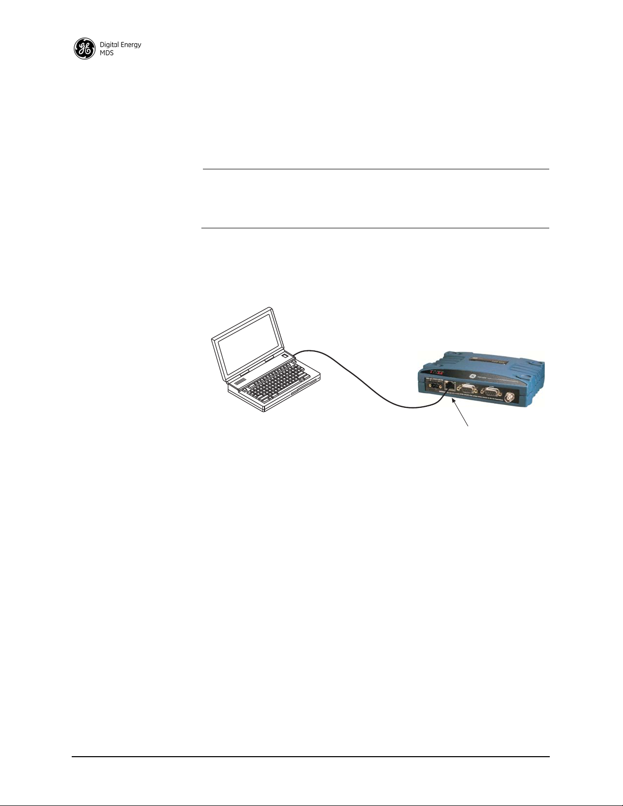
6.0 USING THE DEVICE MANAGER
PC Running Web Browser
Transceiver
RJ-45 to Ethernet Port
The radio contains a built-in management system known as a Device
Manager. This web-based tool is accessed with a PC connected to the
radio’s Ethernet port as shown in Figure 23. It offers an intuitive method
for managing your radio and performing common maintenance tasks.
NOTE: The Device Manager is the preferred method for managing the
transceiver. Menu-based Serial or Telnet management is also
possible. Refer to the SD Serial/Telnet Management Supple-
ment, Part No. 05-6193A01 for details.
If you are using the Device Manager for the first time, refer to “Web
Browser Connection” on Page 28 for instructions on connecting a PC to
the radio and logging into the Device Manager for basic radio setup,
including use of the Setup Wizards.
Figure 23. PC Connection to Radio for Web Management
6.1 Navigating the Screens
Upon login into the Device Manager, the Overview screen appears as
shown in Figure 24. The selection pane at the left side of this screen provides access to any of the available screens. Simply click an item of
interest, and the new screen appears. Sub-level screens are displayed
under the main heading, and may be clicked to open them.
With a desired screen displayed, simply scroll up or down to reach a
required setting or indication. Drop-down boxes or blank fields are provided for entering new information. Once a new parameter is entered,
click Commit Configuration on the right-hand side of the screen to apply
the setting, or select
Undo to cancel it.
34 SD Series Technical Manual MDS 05-4846A01, Rev. G
Page 43

Invisible place holder
Figure 24. Overview Summary Screen
Overview Screen
The Overview screen (Figure 24) provides a read-only view of all key
settings and operating conditions for the radio. The Health & Maintenance
Summary, in particular, can help you quickly spot changes in operating
conditions. By becoming familiar with expected readings, you can identify parameters that are outside their normal ranges, and take corrective
action.
Printout Option Clicking the Printer friendly configuration label at the bottom of the screen
brings up a print-ready report that includes not only the Overview
screen, but all settable items and indications. Printing this report and
keeping it with the manual provides a convenient way of reviewing the
settings for a particular unit at any point in the future.
Logging Out To exit the Device Manager, click Logout in the upper right hand side of
any screen. The session is terminated.
NOTE: To maintain security, it is best to log-out of the Device
Manager as soon as you are done working with it. If you do not
log out, the session automatically ends after 10 minutes of
inactivity.
MDS 05-4846A01, Rev. G SD Series Technical Manual 35
Page 44

6.2 Management Tasks
Table 11 shows a listing of commonly-needed tasks and the appropriate
sections of the Device Manager to refer to. The table can be used as a
quick reference before consulting the more detailed screen information
which follows in this section.
Table 11. Device Manager Quick Reference
Task
Category
View Overall
Status & Performance
If you wish to... Refer to this Screen/Section
View top-level unit information (Owner
Name/Message, Unit Number, IP Address,
Serial No., Firmware version, Run time, Alarm
presence, etc.)
View Radio Performance data (Power Output,
Signal-to-Noise Ratio, Received Signal
Strength, DC Input voltage, operating
temperature)
View Serial No., Model 1 (software), Model 2
(hardware) version, Firmware Version, Build
Date
Information
View Bootloader version information, Active
Firmware Image, Firmware Version level
View Alarm/Event information, I/O Statistics,
Ethernet Statistics
Overview, Page 35
Maintenance & Status>>
Radio Performance,
Page 70
Or: Overview>>
Health & Maintenance
Summary (shows uptime),
Page 35
Overview>>
SD Summary, Page 35
Maintenance & Status>>
Firmware Utilities>>
Version Informati on ,
Page 76
Maintenance & Status>>
Alarm Summary, Page 68
Maintenance & Status>>
Performance, Page 70
36 SD Series Technical Manual MDS 05-4846A01, Rev. G
Page 45

Table 11. Device Manager Quick Reference (Continued)
Task
Category
View/Set Radio (RF) Operating Parameters
If you wish to... Refer to this Screen/Section
Set RF Output Power, Modem Type, RX/TX
Frequency
View/Set Soft-Carrier Dekey status, RX/TX
Time-Out options
View/Set Data-Key and RTS-Key settings
(ON/OFF)
View/Set Push-to-Talk/Clear-to-Send Delay
times (ms)
View/Set Automatic Frequency Correction
(AFC) setting
View/Set Switched Carrier ON/OFF setting (B
Modems)
Configure Listen-Before-Transmit (LBT)
collision avoidance
View Received Signal Strength (RSSI) level Maintenance & Status>>
Key the radio transmitter, view power output Maintenance & Status>>
View local radio emissions to locate possible
interference sources.
Configuration>>Radio,
Basic Settings, Page 41
Configuration>>
Radio>>
Advanced Settings, Page 4 8
Configuration>>
Radio>>
Advanced Settings, Page 4 8
Configuration>>
Radio>>
Advanced Settings, Page 4 8
Configuration>>
Radio>>
Advanced Settings, Page 4 8
Configuration>>
Radio>>
Advanced Settings, Page 4 8
Configuration>>
Features>>
LBT Settings, Page 51
Performance, Page 70
Radio Test>>
RF Keying Test, Page 74
Maintenance & Status>>
Radio Test>>
Spectrum Graph, Page 74
MDS 05-4846A01, Rev. G SD Series Technical Manual 37
Page 46

Table 11. Device Manager Quick Reference (Continued)
Task
Category
View/Set Device Configuration
Security Settings
IP Payload
Configuration
If you wish to... Refer to this Screen/Section
View Serial No., Model 1 (software), Model 2
(hardware) version, Firmware Version, Build
Date
Set Owner Name/Message, enable/disable
Sleep Mode, set COM LED mode, Radio Mode
Configure time delays to identify packets on
serial ports
Configure Media Access Control (MAC) settings Configuration>>
Configure Store and Forward (SAF) Configuration>>Radio>>
Configure Virtual LAN (VLAN) Configuration>>Features>>
Configure Terminal Server 1/2 Configuration>>Features>>
Configure Unit ID and/or DLINK diagnostics
settings
Set Password for radio Configuration>>
Set Device Security (enable/disable local login
requirement, enable/disable Telnet access)
Set Wireless Security parameters (Encryption
on/off, DLINK Security on/off, Encryption
Phrase)
Configure the IP settings (Static IP Address,
Static IP Netmask, Static Default Gateway,
DHCP enable/disable, Virtual Radio
Channels–VRCs)
Configure Ethernet Bridging Configuration>>
Configure the IP Payload settings
(Enable/disable port, set mode, Local IP Port,
Destination IP Address, Destination IP Port,
TCP Keepalive time)
Overview>>
SD Summary, Page 35
Configuration>>
Radio>>Device Settings,
Page 43
Configuration>>
Radio>>
Packet Settings, Page 44
Radio>>
Media Access Control>>
Settings, Page 44
Media Access
Control>>Page 44
VLAN Config., Page 50
Term Srvr COM1/2 Config.,
Page 56
Configuration>>
Radio>>
Diagnostic Settings,
Page 47
Security>>
Login Password, Page 66
Configuration>>
Security>>
Device Security, Page 65
Configuration>>
Security>>
Wireless Security, Page 66
Configuration>>
Security>>
Encryption Phrase, Page 67
Configuration>>
Communication Ports>>
IP Configuration, Page 64
Features>>
Bridge Configuration,
Page 50
Configuration>>
Features>>IP Payload 1, 2,
3, Page 53
38 SD Series Technical Manual MDS 05-4846A01, Rev. G
Page 47

Table 11. Device Manager Quick Reference (Continued)
Task
Category
Serial Port
Configuration
Transceiver Maintenance and Diagnostic Tests
If you wish to... Refer to this Screen/Section
Configure COM1 settings (Startup mode, Data
Baud Rate, Data format, Virtual Radio
Channels–VRCs)
Configure COM2 settings (Mode, Baud Rate,
Format, Buffer on/off, Device Type, Virtual
Radio Channels–VRCs)
View Radio Performance data (Power Output,
Signal-to-Noise Ratio, Received Signal
Strength, DC Input voltage, operating
temperature)
Perform radio tests (Radio Keying, show
Spectrum Graph, run RTU Simulator)
View Bootloader version information, Active
Firmware Image, Firmware Version level
Locally Reprogram the Transceiver via TFTP
transfer
Broadcast Remote Configuration settings to all
radios in the network
Work with Configuration Files...
–Restore Factory default configuration
–Save/restore user configuration
–View/restore key configuration parameters
–Save/load key configuration parameters
using file transfer (TFTP)
Start radio network reprogramming (and monitor
progress)
Perform Ethernet PING to local Ethernet host Maintenance & Status>>
Test communications to specific Remote radio Maintenance & Status>>
Enter a Factory Authorization code, or view
currently enabled features
View active Alarms/Events Maintenance & Status>>
Configuration>>
Communication Ports>>
COM1 Port Settings,
Page 62
Configuration>>
Communication Ports>>
COM2 Port Settings,
Page 63
Maintenance & Status>>
Performance>>
Radio Performance, Page
70
Maintenance & Status>>
Radio Test, Page 72
Maintenance & Status>>
Firmware Utilities>>Version
Information, Page 76
Maintenance & Status>>
Firmware Utilities>>TFTP
Reprogramming, Page 77
Setup Wizards>>Remote
Management, Page 30
Maintenance & Status>>
Configuration Files,
Page 80
Maintenance & Status>>
Firmware Utilities>>
Remote Reprogramming,
Page 78
Radio Test>>Ping Test,
Page 74
Radio Test>>Link Test,
Page 73
Maintenance & Status>>
Firmware Utilities>>
Authorization Codes,
Page 80
Alarm Summary, Page 68
MDS 05-4846A01, Rev. G SD Series Technical Manual 39
Page 48

Table 11. Device Manager Quick Reference (Continued)
Task
Category
Transceiver Maintenance
If you wish to... Refer to this Screen/Section
View logged Events Maintenance & Status>>
Event Log, Page 68
Set alarm signal output (active high/low) Maintenance & Status>>
Conduct an Alarm Test Maintenance & Status>>
View I/O Statistics for COM1, COM2, Ethernet
Port, Remote Programming, Ethernet Interface,
Data Link Layer, and MAC.
and Diagnostic Tests (Cont’d)
View MAC Routes Maintenance & Status>>
Alarm Summary>>
Alarm Signal Configuration,
Page 69
Radio Test>>
Alarm Test, Page 75
Maintenance & Status>>
Performance>>
I/O Statistics, Page 71, and
Ethernet Statistics, Page 71
Performance>>
MAC Routes, Page 72
The remainder of this section covers the screens for Configuration,
Maintenance, and Status of the transceiver. The emphasis is on available
selections, how to access them, and their effect on radio operation. If
you are unsure of the setting required for a particular radio in your network, consult your Network Administrator for assistance.
NOTE: The Device Manager screens shown in this manual were
obtained from a radio operating in a lab environment and are
provided as examples only. Not all content will be legible in
these reduced size examples. Also, the parameters and settings
shown may differ from those seen in field service conditions.
40 SD Series Technical Manual MDS 05-4846A01, Rev. G
Page 49

6.3 Configuration Screens
The Configuration screen (Figure 25) contains a number of key settings
for the radio, including RF parameters, modem selection, packet settings, MAC parameters, and several advanced settings. Individual
screens may be selected beneath
screen.
Configuration on the left side of the
Figure 25. Configuration Screen
(Portion of screen shown—scroll for additional selections)
Radio
Basic Settings The Basic Settings screen contains important RF and modem selections
for radio operation, as discussed below.
RF Output Power (dBm)—The RF output power may be set between
•
20 and 37 dBm (0.1 to 5 watts) in 1 dB increments. The default
setting is
37 dBm. Full power is not required in many cases, and
lower settings will place less demand on the DC power supply
and reduce the chance of interference with other stations. Only
the power necessary to carry out reliable communications should
be used.
MDS 05-4846A01, Rev. G SD Series Technical Manual 41
Page 50

• Modem Type—This setting determines the over-the-air data speed
and bandwidth of the radio’s transmitted signal. All radios in the
network must use the same modem setting to communicate with
each other. The default setting is Modem 9600, but it may be set to
any of the selections shown in Table 12. The table also lists
modem sensitivity ratings for the various modems. Note that
some modem choices are limited based on the model purchased.
Table 12. Modem Selection vs. Speed, Bandwidth & Sensitivity
1, 2
1
1
2
Over-the-air
Speed (bps)
9600 12.5 -112 dBm
4800 12.5 -112 dBm
3200 5.00 -108 dBm
9600 12.5 -106 dBm
9600 12.5 -106 dBm
4800 12.5 -110 dBm
1200 12.5 -110 dBm
19200 12.5 -96 dBm
65000 50.0 -102 dBm
Modem Type
Selection
Modem 9600
Modem 4800
Modem 3200
Modem 9600M
Modem 4800F 4800 6.25 -108 dBm
Modem 9600B
Modem 4800B
Modem BELL
Modem V23 1200 12.5 -110 dBm
Modem 19200N 19200 12.5 -100 dBm
Modem 19200E
Modem 9600N 9600 6.25 -98 dBm
Modem 19200 19200 25.0 -105 dBm
Modem 38400N 38400 25.0 -99 dBm
Modem 65000
1
1, 2
1, 3
1
4
B/W (kHz) Approximate
Sensitivity
5
1) For MDS x710-compatible operation.
2) For ETSI compliance.
3) 3200 bps not applicable to SD4.
4) Only available for SD2 and SD9 units with wide band width hardware option.
Sensitivity is -104 dBm for SD2 and -100 dBm for SD9.
5) SD1 sensitivity may be up to 2 dB less, due to MDS 1710 interoperability
constraints.
• Transmit/Receive Frequency—The receive and transmit frequencies
may be viewed or set here. If no frequencies have been entered,
the fields will be blank and the radio’s PWR LED will flash, indicating that an entry is needed. Frequencies must be entered for the
radio to operate. Consult your station license to determine the
authorized frequencies for your system, and enter them exactly as
listed.
42 SD Series Technical Manual MDS 05-4846A01, Rev. G
Page 51

Device Settings
• Owner Name/Owner Message—An owner name and message may
be entered for the radio for informational purposes. These are
“free-form” fields which do not affect the operation of the radio
in any way. Such fields might be used to identify the network
administrator/company name, and include a site-specific message
(i.e., Unit 2 at North Tower site). Up to 30 alpha-numeric characters
may be entered (there is no minimum), and any printable characters may be used.
• Enable Sleep—Sleep Mode places the transceiver into a “hibernated” low power state, with a nominal current draw of less than
10 mA (at 13 Vdc). “Wake-up” time is approximately 50 milliseconds. Sleep Mode is often used at battery/solar-powered
remote sites to conserve power. An active low on Pin 4 of the
COM2 port is what actually puts the radio to sleep. This signal
must be supplied by the equipment connected to the radio (i.e.,
RTU, PLC, etc.). Sleep mode is not intended for use on master
radios.
• COM LED Mode—The behavior of the radio’s COM/DATA LEDs
may be configured using this box. By default, the LEDs show
dual port activity (Auto). Four LED modes may be selected as
summarized in Table 13.
Table 13. COM/DATA LED Modes vs. Behavior
LED Mode Selection
x710 Monitors TXD on COM2
port
COM1 Activity Monitors any COM1 RX or
COM2 Activity OFF Monitors any COM2 RX or
Dual Port Activity
(Auto Default)
MDS 05-4846A01, Rev. G SD Series Technical Manual 43
TX activity
Monitors any COM1 RX or
TX activity
Serial COM/DATA LED Behavior
LED1 Function LED2 Function
Monitors RXD on COM2
port
OFF
TX activity
Monitors any COM2 RX or
TX activity
Page 52

Packet Settings
• Radio Mode—The radio can operate in one of several modes. The
available selections are:
•Packet
•Packet w/MAC
•x710 (not covered by this manual; See pub. 05-4670A01)
•Transparent
• User Interface—This parameter selects the method of radio management for the Serial/Telnet interface. It has no effect on the web
interface. The default selection is Menu. Alternatively, you may
select CLI, which switches the radio to a Command Line Interface.
With this interface, commands are entered in text-based fashion,
as described in the SD Serial/Telnet Management Supplement,
Part No. 05-6193A01.
Media Access Control (AP menu shown)
• COM1/COM2 Port Inter-Packet Gap—Timing setting used to delimit a
packet on the serial interface for radios operating in Packet Mode.
Too short of a time can cause serial streams to be combined into
one large packet instead of two smaller ones. Too long of a time
can effectively slow down the communications channel. The
Inter-Packet Gap is specified by the number of character times
(the time it takes to send an individual character).
• Transparent RX Timeout (ms)—This setting is similar to the timing
parameters for
COM1/COM2 Inter-Packet Gap, but it applies to data
received over-the-air. It tells the radio how to build an Ethernet
packet based on a transparent data stream received over the radio
channel.
• Device Type—Selects Access Point, Remote, or Store and Forward. An
Access Point serves as the Controller of the RF network. Only
one radio is configured as an AP. Typically this is the “polling
master.” A Remote is connected to end devices in the field (e.g.
PLC, RTU), and there can be any number of these in a network.
Each Remote must have a unique Unit Address, however, which
44 SD Series Technical Manual MDS 05-4846A01, Rev. G
Page 53

is set on the Diagnostic Settings screen (see “Diagnostic Settings”
on Page 47). A Store and Forward device is a radio designated
to retransmit data to/from an outlying Remote (see SAF Network,
below).
• SAF Network—(AP Only) Selects whether or not a Store and Forward radio is present in the network (True), or not (False). Store
and Forward allows extending the coverage area of a network
beyond the primary “footprint” of the system. This can be used to
link outlying Remotes (or Remotes blocked by terrain or other
obstructions) into the network. A detailed discussion on using
Store and Forward is provided below.
• Repeater Network—(AP Only) This setting must be enabled if the
RF network contains a repeater station, or communications will
not work. Remotes automatically learn this setting from the AP.
• Retry Count—If a message is not acknowledged after transmission
it will be resent. This value controls how many times the radio
attempts to resend the message before discarding it.
• Time-to-Live (s)—When a message arrives from the payload interface(s) it is time-stamped and queued for radio transmission. If
the radio cannot transmit the message before the Time-to-Live
(TTL) value, the message is discarded. This helps prevent stale or
old data from being sent over the air.
Store and Forward Operation
Store and Forward (SAF) operation extends a wireless network’s coverage area by electing a device or devices to store data and forward it to
a unit (or units) beyond the reach of the primary coverage area. Conventional RF repeaters receive and transmit data simultaneously. They are
effective at increasing range with low latency, but they are more expensive, have high power consumption, and require more complex installation. SAF-designated units act as smart single radio packet repeaters.
The SAF feature provides a simple, low cost alternative to range extension when a traditional repeater isn’t desired.
Figure 26 depicts a typical single unit SAF network. This network supports a single SAF hop. Chained SAF hops are not allowed. However,
multiple SAF radios are supported provided their RF coverage areas do
not overlap, as this would create radio interference and severely reduce
throughput. SAF will work in conjunction with repeater assemblies to
provide even more extended range.
NOTE: Remote radios being served by a Store-and-Forward unit must
have their TX/RX frequencies set to match those of the
AP/Master station. This allows communication with the SAF
radio, which uses standard Remote TX/RX frequencies.
MDS 05-4846A01, Rev. G SD Series Technical Manual 45
Page 54

Invisible place holder
Figure 26. Store and Forward System Example
Store and Forward is available in Packet w/MAC mode and supports all
MAC features including collision avoidance, retries, and acknowledgements. Furthermore, all major radio features are supported in SAF networks such as diagnostics, over the air programming, bridging, VRCs,
etc.
Dual Duty of SAF Remotes: Since an SAF device doubles as a Remote
radio it may participate in direct exchanges with the Master/AP. By
design, an SAF device is always within the primary coverage area and
has direct communication to the AP. Therefore, all SAF devices act as
both a standard Remote for direct exchanges, as well as an SAF unit for
Store and Forward exchanges. An SAF exchange is defined as any
exchange between the AP and a Remote through an SAF device. In all
cases, the AP still controls the operation of the network.
After sending an SAF data frame, the AP remains idle until the frame
has been delivered to the Remote, at which time it will return to direct
or SAF operation, depending on the message type (unicast or broadcast).
Direct vs. SAF Traffic: Depending on network topology, it is possible
for some Remotes to hear both direct polls from the AP and SAF messages from an SAF-designated Remote. It is more desirable to use the
direct traffic to avoid the latency of going through the SAF link, and the
radio’s firmware handles this situation automatically. SAF frames are
ignored when the direct path is available. The system is dynamic; if the
direct path becomes unavailable for any reason, it quickly switches to
the SAF path to provide continued operation.
Traffic Routing: Typically, network radios are immobile, but fading
may cause paths to come and go. Because of this, the AP device implements routing to each Remote device. This ensures that only SAF traffic
passes through SAF Remotes. Direct traffic is terminated at the local
coverage area, keeping efficiency high. The transceiver achieves these
steps automatically, and does not require user input. The following is an
explanation of how this routing scheme is achieved.
46 SD Series Technical Manual MDS 05-4846A01, Rev. G
Page 55

Diagnostic Settings
Initially, all Remote device routes are unknown. The AP assumes that
all undiscovered Remotes can potentially be on the SAF link. Once a
Remote attempts to communicate upstream to the AP, the AP is aware
of the Remote's path based on the exchange type, direct or SAF. The AP
stores this information in a database linked to the Remote's address.
Future exchanges with the Remote initiated by the AP will reference this
database and the AP chooses the most recent exchange type.
Upstream, the Remote can freely choose the best exchange type based
on what is available at the time. The AP continuously updates the
routing database on each exchange to a Remote. If a Remote has not
been heard from within a certain time frame, the route is reset to initial
conditions so that the route may be “relearned.” This does not cause any
additional delay and is implemented only as a safeguard. This allows for
highly efficient and adaptable routing to each Remote device without
the overhead of a routing protocol, and saves critical bandwidth.
• Unit #—This parameter identifies the radio in the wireless network
with a specific ID during diagnostic sessions.
• Dlink T ype—This setting identifies the radio as either a Node, Root,
Repeater, Peer, or Gate. Each of these are operating modes of the
transceiver with respect to diagnostic/management activities.
(See “Performing Network-Wide Remote Diagnostics” on
Page 89 for details.)
Dlink Statu s —This item is used to enable or disable diagnostics
•
functionality. Setting it to ON configures the radio to pass the
diagnostic link protocol (DLINK) over the radio’s COM1 management port.
• Dlink Baud Rate—This setting determines the COM1 serial data
diagnostics communication rate in bits-per-second (bps).
•
Dlink TCP Access—This setting enables DLINK over Ethernet via
TCP. This allows an external NMS to manage the radio without
the need to dedicate a serial port for this function.
Dlink TCP Port—This setting specifies the TCP port for DLINK
•
communication. The address for Ethernet-based DLINK communication is given by the radio's IP address (from the general settings screen) and the port number specified here.
MDS 05-4846A01, Rev. G SD Series Technical Manual 47
Page 56

Advanced Settings
• Soft-Carrier Dekey (ms)—Specifies how long (in ms) to wait after
the removal of the keying signal before actually dropping the
transmitter’s carrier. The default setting is 0, but it may be set to
any value up to 255 ms. In most cases, no change is required from
the default setting. A possible exception is when the transceiver
is inter-working with certain early-generation MDS radio equipment.
• RX Time-Out Enable—Enables or disables the RX time-out function. RX time-out protects against a receiver which fails to
receive data for a period exceeding the RX time-out delay setting
(see below). When the time is exceeded, an alarm is issued. The
alarm may be used to signal switchover to an alternate unit in
redundant systems. The RX time-out is cleared when the radio
receives a new Carrier Detect signal. The default selection is OFF
(no RX time limit).
• RX Time-Out Delay (min) —Sets the time delay, after which an alarm
is issued when no signals have been received. The default setting
here is 1111 minutes.
• TX Time-Out Status—Enables or disables the TX Time-Out func-
tion. This protects against a transmitter which remains keyed for
a period exceeding the TX Time-Out Delay setting (see below).
When this time is exceeded, the transmitter is taken offline, preventing disruption of the wireless network. The TX time-out is
cleared when the keying source goes away and the radio keys
again.The default selection is
ON (transmitter shuts down when
time limit is reached).
• TX Time-Out Delay (sec)—Sets the time delay, after which a keyed
transmitter is taken offline. The default time-out setting is 30 seconds.
•
Datakey—Determines whether or not the radio is configured to
key (transmit) upon receipt of payload data at its interface port.
The default setting is ON.
• RTS Key—Determines whether or not the radio is configured to
key (transmit) upon receipt of an RTS (ready to send) signal at its
interface port. The default setting is OFF.
48 SD Series Technical Manual MDS 05-4846A01, Rev. G
Page 57

• Push-To-Talk Delay (ms)—Allows programming a brief time delay
after a keying event, which must expire before the radio is
allowed to transmit. The allowable range is 0 to 255 ms, with the
default being 0.
• Clear-To-Send Delay (ms)—Allows programming a brief time delay
between when an RTS (ready-to-send) signal is received and
when the CTS (clear-to-send) signal is returned. The allowable
range is 0 to 255 ms, and the default is 0.
• Automatic Freq. Correction—Automatic Frequency Correction
(AFC), is used to counteract the slight RF frequency drift that
may occur over time or through wide swings of ambient temperature.
• Switched Carrier (B Modems)—In some networks, the master unit is
not keyed continuously (ckeyed), and transmits only when it has
data to send to Remotes. This is known as Switched Carrier operation. The Switched Carrier setting is only for use on radio
modems with “B” suffixes (for compatibility with MDS x710
radios). In such networks, the remote radios should have the
Switched Carrier setting turned ON. The default setting is OFF which
assumes B-modem operation with a continuously keyed master.
Ckey Operation only applies to Master units operating in
full-duplex mode only. Master units in B-modem networks will
have SWC set to ON regardless of ckey being on or off.
• RX Signal Attenuation—This setting is intended for use in very
strong signal environments (-20 dBm or stronger). It should be
kept off when working with normal or weak signal levels.
• Force DCD to Asserted—Some systems require a constant Data
Carrier Detect (DCD) signal. This setting allows the radio to be
configured to provide a DCD signal without the need for special
cabling.
MDS 05-4846A01, Rev. G SD Series Technical Manual 49
Page 58

Bridge Configuration
Features
• Bridge Mode—Used to enable or disable Ethernet Bridging on the
radio. Default setting is OFF.
• Basic Bridge Filter Sel—Sets the type of bridge filter to be used.
Available selections are: Broadcast/Unicast (All), Unicast and ARP,
and Unicast Only.
• Adv Bridge Filter Status—When on, this filter bridges the Ethernet
traffic received from a specific Ethernet-enabled device matching
one of the Adv Src Addr Filter Values (see below).
• Adv Src Addr Filter Val—Sets the Advanced SRC Address Filter
Values. Four address fields are available. If the Adv Bridge Filter
Status is on, and an incoming Ethernet frame src addr matches
any of these values, the radio bridges the frame. Otherwise, it is
dropped by the radio. The entry format must be xx:xx:xx:xx:xx:xx.
VLAN Configuration A VLAN is essentially a limited broadcast domain, meaning that all
members of a VLAN receive broadcast frames sent by members of the
same VLAN but not frames sent by members of a different VLAN.
The radio supports port-based VLAN at the Ethernet interface and over
the air, according to the IEEE 802.1Q standard. When VLAN Mode is
enabled, the wireless port of both AP and remote radios act as a trunk
port.
The Ethernet port of an AP radio is normally configured as a trunk port.
This type of port expects incoming frames to have a VLAN ID and sends
outgoing frames with a VLAN structure as well. The Ethernet port of a
Remote radio can be configured as an Access Port or as a trunk port.
When the Wireless or Ethernet port (AP or Remote) is configured as an
Access Port, the radio tags incoming traffic with a VLAN ID, and strips
the tag before sending out traffic. This traffic is known as the Data
VLAN. Additionally, a second VLAN is assigned for other traffic that
is terminated at the radio, such as Web, Telnet, DLINK over TCP, TFTP
reprogramming, etc. This traffic is known as the Management VLAN.
Traffic directed to the terminal server or IP payload service should be
sent via the Data VLAN.
50 SD Series Technical Manual MDS 05-4846A01, Rev. G
Page 59

When the Ethernet port of a Remote is configured as a VLAN trunk, the
radio expects all incoming Ethernet frames to be tagged, and passes
through all outgoing frames as received from the wireless link with the
unchanged VLAN tag.
• Mode—Defines the Ethernet port as Trunk, Access, or Disable (an
untagged port). The default setting is
Disable. The mode should
be the last parameter changed when configuring the VLAN
feature, since any Telnet or web connections will be lost after
it is changed. Also, configure the appropriate IP and IP2 settings
before changing this parameter.
•
Data ID—Defines the VLAN ID assigned to the AP’s LAN traffic
to be delivered to an Access Port, and the terminal server service,
or the IP payload service. The ID is used for filtering and tagging
purposes. Any valid ID from 1 to 4095 may be entered. The
Default Data VLAN ID is 2.
Listen Before Transmit (LBT) Settings
• Mgmt ID—Defines the VLAN ID assigned to the AP’s LAN traffic
that is to be delivered to the radio. Note that traffic for the terminal server and IP payload service is expected in the data VLAN.
This ID is used for filtering and tagging purposes. Any valid ID
from 1 to 4095 may be entered. The Default Mgmt VLAN ID is 1.
• Gateway IF—Defines the VLAN that contains the default gateway
in the radio. Available selections are Mgmt and Data. The default
setting is Mgmt.
NOTE: The VLAN Mode parameter must be consistent at both the AP
and Remote radios in order for data to flow correctly. Failure
to do so may result in data not being transported correctly even
when the radios are able to communicate over-the-air via an
RF link.
The transceiver provides a legacy collision avoidance scheme called
Listen Before Transmit (LBT). It employs P-Persistent CSMA protocol,
which senses channel usage and inhibits transmission if the channel is
currently in use. CSMA is an abbreviation for Carrier Sense Multiple
Access. This setting is superseded by Packet w/MAC and should only
be used in legacy systems and special use cases. Packet w/MAC is the
preferred method for collision avoidance.
NOTE: The Listen Before Transmit (LBT) feature requires radios to
be configured for Packet Mode operation. Packet w/MAC
operation provides an alternative method for media access.
MDS 05-4846A01, Rev. G SD Series Technical Manual 51
Page 60

• Listen Before Transmit—Used to activate or deactivate LBT when
this feature is authorized in the radio.
• LBT Behavior—LBT can be configured to behave in one of two
ways; either listen on the radio’s transmit frequency (TX) or listen
on the radio’s receive frequency (RX). Typically, Remote radios
are configured to Listen on RX (the default selection) to avoid collisions with the Master unit. In peer-to-peer configurations, Listen
on TX may be preferred. Optimal choices depend on the data trans-
mission characteristics of the connected system.
• Min/Max Channel Wait (ms)—These settings refer to the time period
(in milliseconds) to wait after the channel is free before transmission is allowed.
Minimum wait time: Normally, the minimum channel wait time
should not be changed from its default setting of 0 ms unless performing advanced operations, such as staggering the responses
from multiple Remotes.
Maximum wait time: Normally, this setting should not be
changed from its default of 100 ms unless performing advanced
operations. Some examples of when this may be beneficial
include:
• There is a need to stagger responses from several Remote
radios.
• The transmission latency from the time the channel is free is
too high, in which case a lower value can be entered.
• Collisions over the air are too high, in which case a higher
value can be entered.
NOTE: The lower the value of the Maximum Wait Time, the higher
the chances of collisions occurring over-the-air. Conversely,
the higher the value of the Maximum Wait Time, the higher the
transmission latency.
• Timeout (ms)—Provides a setting for the maximum wait time (in
milliseconds) for the channel to become free. When this time is
exceeded, the radio follows the action defined in the Packet Action
on Timeout
52 SD Series Technical Manual MDS 05-4846A01, Rev. G
setting (either Drop or Send).
Page 61

• Packet Action on Timeout—Determines what to do with a packet
once the timeout period has expired and the channel is still not
available. If set to Drop, the packet is discarded. If set to Send,
transmission of the packet is attempted despite the channel being
busy.
• Clear Channel RSSI (dBm)—LBT works by sensing the presence of
a carrier signal on the radio’s operating frequency. If a carrier is
present, transmission is inhibited. The Clear Channel RSSI setting
allows a threshold to be set which, when equaled or exceeded,
declares the channel busy and therefore unavailable for transmitting.
IP Payload Configuration (1/2/3)
This section describes how to setup and configure the radio for
exchanging IP/Ethernet Payload data with Remote radios. It is an efficient feature that supports Ethernet connectivity with maximum
over-the-air (OTA) efficiency for UDP and TCP data streams. Remote
radios receiving the data can then forward this traffic to their serial ports
or Ethernet port. This feature is particularly useful for adding Ethernet
devices to a mixed system using MDS SD and x710 Transceivers. This
feature is different than Ethernet Bridging, which is described on Page
50.
NOTE: To make use of this feature, the radio must be properly autho-
rized for Ethernet data. If it is not, contact your sales representative for further information.
It is helpful to understand that IP data is terminated at the radio, yet the
payload data is transmitted OTA. As such, the radio acts as a terminal
server converting IP data into a serial “over-the-air port.” In other
words, a transmitting radio receives an IP message, strips off the IP
headers, and sends it over the air with VRC identification (VRC-1,
VRC-2, or VRC-3). A receiving radio may then be set up, for example,
to have COM2 or an IP port deliver all VRC-1 traffic.
The radio supports Ethernet operation on three IP payload ports. These
settings are made on the IP Payload Configuration Menu (1, 2, or 3)
as shown in the screen which follows later in this section. In the Master
unit only, Multihost may need to be enabled if more than one IP Payload
port is required.
IP Payload is intended to be used in a poll-response system. An Ethernet
device at the Master radio sends UDP/TCP poll messages to the
Master’s Ethernet port which is configured to listen for data. The poll is
sent OTA and a RTU/PLC attached to one of the Remote radios (via
serial or Ethernet) responds. The response is sent OTA back to the
Master radio. The Master radio then sends the response back to the
polling station via Ethernet.
MDS 05-4846A01, Rev. G SD Series Technical Manual 53
Page 62

When configuring this feature, you are notified of the success or failure
of the operation. Additionally, Ethernet and OTA statistics can be monitored to inspect the success of the poll-response communication.
The following additional points apply to Ethernet payload operation:
• To make efficient use of limited bandwidth, this feature transports the payload content of Ethernet data to be sent over the air.
• This feature does not bridge Ethernet networks separated by
radios. For more information, see Ethernet Bridging found on
Page 50.
•A broadcast poll-response network is assumed, where addressing
information is contained in the payload portion of the UDP/TCP
messages.
NOTE: Screen selections vary depending on the radio mode selected.
Three such screens are provided for Payload 1, 2, and 3.
• Status—Enables or disables the IP Payload port.
• Mode—The operating mode for the IP port may be set to UDP
, TCP Client Socket, TCP Server Socket, or TCP Server/Client
Socket
to match the service in which it will operate.
Socket
•
Talk on/Listen to—Any combination of the three Virtual Radio
Channels may be entered in these fields. For more information on
how VRC settings are used, refer to the SD Serial/Telnet Manage-
ment Supplement, Part No. 05-6193A01.
Local Radio IP Port—Used to specify a port number for the RJ-45
•
modular connector on the radio’s front panel. As a general rule,
port numbers below 2000 should be avoided, as some are
reserved for special applications in data networks.
• Destination IP Address—Specifies the IP address associated with
the device connected through the RJ-45 modular connector on the
radio’s front panel (typically a PC). Any valid IP address may be
entered.
•
Destination IP Port—Used to specify a port number for the RJ-45
modular connector on the connected device (typically a PC). Port
numbers below 2000 should be avoided, as some are reserved for
special applications in data networks.
54 SD Series Technical Manual MDS 05-4846A01, Rev. G
Page 63

• TCP Server IP Address—IP address of the TCP server being used.
• TCP Server IP Port—Port number of the TCP server being used.
• Connection Timeout—Used to specify a time in seconds, after
which the connection will be dropped following a period of inactivity.
• Persistent Connection—When set to Yes, the connection to the
server is maintained continuously, even during periods of inactivity.
• Committing Configuration—Once you are satisfied with all of the
settings on the screen, you make them active by clicking this button. The message Changes committed appears at the bottom of the
screen to confirm the action.
• Restoring Configuration—In some cases, you may wish to revert to
the previous configuration of the screen, prior to any changes
being committed. This might be useful if one or more settings
were inadvertently changed and you wish to return to a “known
state.” To restore the prior settings, simply click Restore Configura-
tion.
Understanding the Use of Virtual Radio Channels (VRCs)
The use of Virtual Radio Channels (VRCs) may require additional
explanation for new users of the feature. VRCs allow over-the-air data
to be directed to specific interface ports (IP or Serial) on the radio. Conceptually, this can be pictured as creating “pipes” for delivery of data to
the desired radio interfaces.
VRC works by associating data from a specific port (IP and Serial) with
a VRC channel number (1, 2, or 3). Each port at the receiving end then
filters incoming data based on the associated VRC number.
NOTE: The Virtual Radio Channel (VRC) feature is only supported in
Packet and Packet w/MAC modes. It is not supported in Transparent or x710 mode.
To create the “pipes” that direct data to the desired ports, a route must
be established using the IP Payload Configuration Menu (or the
COM1/COM2 Settings Menu for serial data). The default setting is to
listen to all channels.) The
Talk on parameter is used to specify the VRC
used for sending the data stream out, while the Listen to parameter specifies the VRC(s) for incoming data. Use of these parameters was
described earlier in this section.
Any combination of the three VRC numbers may be entered in the selection fields. Figure 27 illustrates the relationship between the VRC settings and the routing of data between units.
MDS 05-4846A01, Rev. G SD Series Technical Manual 55
Page 64

Invisible place holder
RADIO 1
RADIO 2
IP Payload 1 Data
Ethernet/IP RTU
IP Payload 1 Data
(Talk on VRC-1)
Serial COM2 Data
(Talk on VRC-2)
(Listen on VRC-1)
Serial-Based RTU
Serial COM2 Data
(Listen on VRC-2)
Terminal Server COM1/2 Configuration
The radio’s Terminal Server feature allows IP addressing of the COM1
and COM2 serial interface ports. Data from these ports is sent over the
air as encapsulated IP packets. At the receiving end, the data is decapsulated and delivered to the appropriate COM port(s). In contrast to the
radio’s IP Payload feature, having a terminal server at the Remotes
means that Ethernet data can be delivered to specific devices connected
to these radios. Terminal Server settings, examples, and additional benefits are described in the following paragraphs.
The image below shows the Device Manager’s Terminal Server configuration screen. Two such screens are provided in the Device Manager;
one for COM1 and another for COM2. Here, the behavior of the terminal server is set and applied. The Terminal Server must be enabled
Figure 27. Virtual Radio Channel (VRC) Concept
56 SD Series Technical Manual MDS 05-4846A01, Rev. G
Page 65

and configured in all radios requiring IP encapsulation of serial data.
Proper configuration of the serial ports is also required, using the Com-
munications Ports
section of the Device Manager.
NOTE: Available selections vary depending on the mode selected.
• Status—Enables or disables the Terminal Server feature.
• Mode—Sets the operating mode for the IP port. It may be set to
UDP Socket, TCP Client Socket, TCP Server Socket, or TCP Server/Client
to match the service in which it will operate.
Socket
• Local Radio IP Port—Used to specify a port number for the RJ-45
modular connector on the radio’s front panel. As a general rule,
port numbers below 2000 should be avoided, as some are
reserved for special applications in data networks.
• Destination IP Address—Specifies the IP address associated with
the device connected through the RJ-45 modular connector on the
radio’s front panel (typically a PC). Any valid IP address may be
entered here.
• Destination IP Port—Used to specify a port number for the RJ-45
modular connector on the connected device (typically a PC). Port
numbers below 2000 should be avoided, as some are reserved for
special applications in data networks.
• TCP Server IP Address—IP address of the TCP server being used.
• TCP Server IP Port—Port number of the TCP server being used.
Socket State—Provides status on the configuration (i.e., whether
•
or not the terminal server port is active).
•
Commit Configuration—Clicking this button causes any “staged”
parameter changes to be activated and saved to non-volatile memory. Unlike most other attributes, terminal server attributes don't
automatically “take” after making a change. Similar to the Ethernet settings, many items only make sense to change as a block,
and this is why the
Commit Configuration button is provided.
• Refresh/Auto—Clicking the Auto button causes the Web/UI interface to update and load the latest saved data. Clicking
Refresh
forces an instant update. A periodic refresh update interval is provided for the
Auto parameter.
MDS 05-4846A01, Rev. G SD Series Technical Manual 57
Page 66

The Terminal Server supports the following communication protocols:
• Point-to-Point: TCP or UDP
• Point-to-Multipoint1: UDP (One of the Destination IP Addresses
is a multicast IP address)
• Multipoint-to-Multipoint1: UDP (Two or more of the Destination
IP Addresses are a multicast IP address)
1
Data from local multicast IP addresses is always delivered to the socket layer
by the radio's TCP/IP stack. Therefore, to receive data from local multicast IP
addresses, simply set the Local Radio IP Port equal to the destination IP port
of the multicast IP packet.
Using the Terminal Server—Typical Example
The following describes a Terminal Server implementation in a radio
network. Figure 28 below is referenced in this discussion.
Figure 28. Terminal Server Example
IP/Radio Network Setup and Configuration
The following conditions are assumed for this example:
• Radio (RF) link is good between AP and Remote 1, and AP and
Remote 2.
• IP addresses are properly configured as shown in Figure 28.
• Packet w/MAC mode is enabled in all radios, and the MAC Device
is set to AP in radio with the IP address equal to 192.168.1.2.
Type
• Ethernet Bridge is enabled in all radios.
58 SD Series Technical Manual MDS 05-4846A01, Rev. G
Page 67

Serial Addressability
This example shows that it is possible to communicate to specific serial
devices (e.g., PC 2 COM1, and PC 3 COM1) over the radio network.
Note that TCP is used as the transport layer for communication here,
which provides data reliability at the application level.
1. Configure Remote 1 and Remote 2 by navigating to the Term Srvr 2
COM2 Configuration
screen and setting the parameters as listed below.
(Note that an Ethernet connection to Remote 1 and Remote 2—not
shown in Figure 28— will be required for this step, unless Telnet is
used.)
Status: Enabled
Mode: TCP Server Socket
Local Radio Port: 30000
Connection Timeout: 0 Seconds
Persistent Connection: Yes
2. Navigate to the COM2 Port Settings of Remote 1 and Remote 2 and
configure them as listed below (note that VRCs are not used):
Mode: RS232
Baud Rate: 115200 bps
Format: 8 char bits, no parity, 1 stop bit
Buffer: Data Handling ON
Device: DCE
Talk on: VRC-1
Listen to: VRC-1
3. Click Commit Configuration after the changes are made.
To test the functionality of the Terminal Server, open a HyperTerminal
session on PC1 and connect to the Remote Terminal Server as shown in
Figure 29.
Invisible place holder
Figure 29. Remote 1 Terminal Server Connection
On PC2, Open a HyperTerminal session and connect to Remote 1’s
COM2 port as shown in Figure 30.
MDS 05-4846A01, Rev. G SD Series Technical Manual 59
Page 68

Invisible place holder
Figure 30. Remote 1 COM2 Port Connection
On PC1, open a HyperTerminal session and connect to Remote 2 Terminal Server as shown in Figure 31.
Invisible place holder
Figure 31. Remote 2 Terminal Server Connection
On PC3, open a HyperTerminal session and connect to Remote 2’s
COM2 port as shown in Figure 32.
Figure 32. Remote 2 COM2 Port Connection
60 SD Series Technical Manual MDS 05-4846A01, Rev. G
Page 69

Type “hello” in the Remote 1 terminal server window. Note delivery of
the message only to the Remote 1 COM2 Port window (see Figure 33).
Type “hi” in the Remote 1 COM2 port window. Note delivery of message only to the Remote 1 terminal server window. This verifies proper
delivery and routing of traffic.
Figure 33. Remote 1 Terminal Server/COM2 Port Communication
Type “how are you” in the Remote 2 terminal server window (see
Figure 34). Note delivery of the message only to the Remote 2 COM2
Port window. Type “good” in the Remote 2 COM2 Port window. Note
delivery of message only to Remote 2 terminal server window.
Figure 34. Remote 2 Terminal Server/COM2 Port Communication
Multihost Settings
Use only if operating
(
in Packet mode
without
MAC)
Multihost is a legacy feature that has been superseded by the Packet
w/MAC feature. It should only be used in legacy systems or in special
use cases.
The Multihost Settings screen is used only when Packet w/MAC mode
is not selected. It provides an alternative way to run multiple host applications at the master unit, which may be operating on different computers. Multihost operation is described in more detail in the SD
Serial/Telnet Management Supplement, Part No. 05-6193A01.
MDS 05-4846A01, Rev. G SD Series Technical Manual 61
Page 70

COM1 Port Settings
Packet w/MAC operation replaces multihost operation, and is the recommended method for passing multiple data streams. See “Device Settings” on Page 43 for instructions on setting the Radio Mode to Packet
w/MAC.
Multihost Enable—Enables or disables multihost capability.
•
• Multihost Delay—Sets the desired delay time (in ms) for switching
between hosts during multihost operation.
Communications Ports
• Startup Mode—The default mode for COM1 is Console when the
transceiver is first powered up, but the startup mode may also be
set to Data if the port is to be used for passing payload data.
• Current Mode—The mode setting for the COM1 port may be
changed on demand (Console or Data) using this selection.
• Data Baud Rate—The default data rate for COM1 is 115200 bps, but
it may be set to any of the following speeds: 300, 1200, 2400,
4800, 9600, 19200, 38400, 57600, 115200.
Data Format—The default data format for the transceiver is 8 char-
•
acter bits, no parity, and 1 stop bit (8N1). A number of settings are
possible as listed below:
8 character bits, no parity, 1 stop bit (Default)
8 character bits, no parity, 2 stop bits
8 character bits, odd parity, 1 stop bit
8 character bits, odd parity, 2 stop bits
8 character bits, even parity, 1 stop bit
8 character bits, even parity, 2 stop bits
7 character bits, no parity, 1 stop bit
7 character bits, no parity, 2 stop bits
7 character bits, odd parity, 1 stop bit
7 character bits, odd parity, 2 stop bits
7 character bits, even parity, 1 stop bit
7 character bits, even parity, 2 stop bits
62 SD Series Technical Manual MDS 05-4846A01, Rev. G
Page 71

• Talk on/Listen to—Any combination of the three Virtual Radio
Channels may be entered in these fields. Refer to the SD
Serial/Telnet Management Supplement, Part No. 05-6193A01 for
more information.
Term Srvr Status—Indicates whether the radio’s terminal server is
•
enabled or disabled.
COM2 Port Settings COM2 is the standard port used for connection of serial payload data.
COM2 Port Settings screen contains a number of settings that may be
The
configured to suit the needs of your system.
•
Mode—The COM2 port can operate in either RS-232 or RS-485
mode. The default is RS-232.
• Baud Rate—The default data rate for COM2 is 9600 bps, but it may
be set to any of the following speeds: 300, 1200, 2400, 4800,
9600, 19200, 38400, 57600, 115200.
• Data Format—The default data format for the transceiver is 8 character bits, no parity, and 1 stop bit (8N1). A number of settings are
possible as listed below:
8 character bits, no parity, 1 stop bit (Default)
8 character bits, no parity, 2 stop bits
8 character bits, odd parity, 1 stop bit
8 character bits, odd parity, 2 stop bits
8 character bits, even parity, 1 stop bit
8 character bits, even parity, 2 stop bits
7 character bits, no parity, 1 stop bit
7 character bits, no parity, 2 stop bits
7 character bits, odd parity, 1 stop bit
7 character bits, odd parity, 2 stop bits
7 character bits, even parity, 1 stop bit
7 character bits, even parity, 2 stop bits
MDS 05-4846A01, Rev. G SD Series Technical Manual 63
Page 72

• Buffer—The transceiver’s buffer provides a way of handling data
“over-runs,” where more data is passing through the COM2 port
than can be immediately handled by the unit. When the buffer is
on, any such data is stored up and processed in the appropriate
order. Available selections are Data Handling ON or Data Handling
.
OFF
• Device—This setting controls the device behavior of x710 legacy
radios. It does not apply to packet or Ethernet radios, and may be
disregarded for these later models.
•
Talk on/Listen to—Any combination of the three Virtual Radio
Channels may be entered in these fields. For more information on
how these settings are used, refer to the SD Serial/Telnet Manage-
ment Supplement, Part No. 05-6193A01 more information.
• Term Srvr Status—Indicates whether the radio’s terminal server is
enabled or disabled.
NOTE: The radio can operate in RS-422 mode when RS-485 is
selected.
IP Configuration The IP Configuration screens contain various settings for the IP data
stream. Each item is listed below along with an explanation of the
parameter. Note that the bottom of the screen displays the current set-
tings that have been applied to the radio in a read-only fashion.
Current IP Address—Read-only indication of the curr ent IP address
•
programmed.
• Current Subnet Mask—Read-only indication of the subnet mask
programmed.
•
Current Default Gateway—Read-only indication of the current
default gateway programmed.
• Static IP Address—The radio requires a local IP address to support
remote management and serial device (terminal server) services.
An IPv4 IP address should be entered in this field, unless DHCP
is enabled, in which case it is not required.
64 SD Series Technical Manual MDS 05-4846A01, Rev. G
Page 73

Device Security
• Static IP Netmask—This refers to the radio’s IPv4 local subnet
mask. This parameter is used when the radio attempts to send a
locally-initiated message, either from the terminal server, or a
management process. You do not need to define it if DHCP is
enabled.
• Static Default Gateway—This is the IPv4 address of the default gateway device, typically a router connected to the radio.
• DHCP—Dynamic Host Configuration Protocol (DHCP) handles
the assignment of IP parameters (Address, Netmask, Gateway) to
all units in a network, and allows for introducing new devices on
the network with minimal manual intervention. The assigned
parameters are valid for a specific “lease” time, at which point
they can be reassigned or renewed.
Security
The transceiver offers a number of safeguards against unauthorized
management access and protection of payload data. All of these features
are accessed via the security configuration screens.
• Local Security—This parameter is used to specify whether or not a
local log-in is required when using the transceiver’s menu system.
The default setting is Local Login Required, and is appropriate for
most circumstances. Setting this parameter to No Local Login
Required might be useful in cases where only a small number peo-
ple with administrative duties have physical access to the radio,
and need to access the menu frequently. In this mode, the menu
operation behaves identically to the Administrator level login.
Telnet Access—Telnet access is a powerful feature that allows
•
management of the radio via an Ethernet connection. This may be
done locally, using a cable connected to the management PC, or
at any distance using an IP/Ethernet network connection. Telnet
access is also possible over the air if the Ethernet Bridging feature
is enabled. Any user with the IP address of the radio can log in to
the unit with this method.
• Disable Web Access—Web access to the unit’s Device Manager is
normally enabled. Click this item to disable web access. A warning message appears to confirm disabling of web navigation.
MDS 05-4846A01, Rev. G SD Series Technical Manual 65
Page 74

Wireless Security
Login Password
NOTE: If the radio login password is lost or forgotten, contact GE
MDS for assistance. Proof of authorized user is required for a
new password, and the radio will revert to its default settings.
It is recommended that users periodically export their configuration file so that it can be loaded back into the radio if their
old one requires replacement.
• Payload Encryption—When on, applies encryption to payload data
stream. The default selection is
OFF.
• Dlink Security—Applies security restrictions to network-wide
diagnostic data. The default setting is OFF. If Dlink Security
enabled, users performing network-wide diagnostics must log in
before being able to change the configuration of the radio via
Dlink.
• Administrator Password—When the transceiver is shipped from the
factory, the password is normally set to the default entry of
admin.
It is recommended that it be changed at the time of installation to
one that is known only to the Administrator or authorized user of
the system. The password should be changed periodically to
maintain the best security.
Passwords are case sensitive and may use up to 13 alpha-numeric
characters. Do not use punctuation mark characters. You will be
required to enter the current password to set a new one. Follow the
prompts, and refresh your web browser (typically View>>Refresh
or
View>>Reload at the top menu bar) to apply the change to all
pages.
TIP: For enhanced security, consider using misspelled words, a combi-
nation of letters and numbers, and a combination of upper and
lower case letters. Also, the more characters used (up to 13), the
more secure the password will be. These strategies help protect
against sophisticated hackers who may use a database of common
words (for example, dictionary attacks) to determine a password.
66 SD Series Technical Manual MDS 05-4846A01, Rev. G
Page 75

Encryption Phrase
• Encryption Phrase—If encryption has been enabled, a valid
“phrase” must also be set. Both the sending and receiving station
must have the same phrase for communication to occur. The
phrase must have at least 8 characters (maximum of 37), and any
printable character may be used.
6.4 Maintenance & Status Screen
The Maintenance & Status screen (Figure 35) provides access to several
tools used in testing the radio and performing routine management tasks.
Individual screens may be selected beneath Maintenance & Status at the
left side of the screen.
Figure 35. Maintenance & Status Screen
MDS 05-4846A01, Rev. G SD Series Technical Manual 67
Page 76

Event Log
The Event Log is used to display all events stored by the transceiver,
even if the radio has been power-cycled. It also shows a running total of
the alarms stored.
• Total Event Log Events—Displays the number of events that have
been logged by the transceiver. To view the Event Log, click Show
. The listed events can be cleared by clicking Clear Log. (You
Log
will be challenged by a caution message to verify that you intend
to clear the event log.)
• Show Log—Displays a detailed listing of each event.
• Clear Log—Erases the stored listing of events.
• Export Log—Used to save the log data as a text file in the desired
location on the PC.
Alarm Summary
Alarms This screen shows the current major and minor alarms, if any, since
power-up of the transceiver.
Refresh—Clicking this button manually updates the listed alarms
•
with the latest information.
• Auto—Initiates automatic updating of alarm listings. A time (in
seconds) may also be set in the box provided, to specify how often
alarms/events are updated.
68 SD Series Technical Manual MDS 05-4846A01, Rev. G
Page 77

Status Conditions and Events
This screen shows status conditions reported since power-up of the
transceiver. This includes normal, informational events such as booting
up the system and reinitializing.
Refresh—Clicking this button manually updates the listed events
•
with the latest information.
•
Auto—Initiates automatic updating of event listings. A time (in
seconds) may also be set in the box provided, to specify how often
alarms/events are updated.
Alarm Signal Configuration
This screen contains settings to determine what events are detected, and
what will be done with them. At the bottom section of the screen are
selections for displaying specific alarms, conditions, and informational
events that will be reported. Select events to be reported by clicking the
box to the left of the item. The sample image below shows the first six
events in the bottom portion of the screen. Additional listings are visible
by scrolling down.
Alarm Signal Sense—This parameter may be set to either Active
•
or Active Low. An active high means that Pin 6 on the COM2
High
port will output a high DC signal when an alarm exists. (This is
the default behavior.) An active low means that Pin 6 on the
COM2 port will output a low DC signal when an alarm exists.
Select the desired behavior in the drop-down box and click
Alarm Signal Sense
to apply the setting.
Set
MDS 05-4846A01, Rev. G SD Series Technical Manual 69
Page 78

• Set Signal by Class—Here, you can specify what classes of alarms
result in an signal being produced by the alarm output line. The
choices are:
Never assert Alarm Signal
Assert Signal on Major Alarm
Assert Signal on Major or Minor Alarm
Assert Signal on Any Alarm or Status
• Set Alarm Bits—This button is used to set the selections made in
the check box list below it. First, you must select which specific
alarms will result in a signal being produced by the alarm output
line. To set an alarm/message for reporting by the output line, you
click the check box next to an item of interest. To clear a check
box, simply click it again. When you are finished with the selections, click the Set Alarm Bits button.
• Undo—This button is used to return the screen to its original
selections. It clears any selections made prior to clicking the Set
Alarm Bits button.
Performance
Radio Performance This screen contains several measurement parameters that can be used
to check the operating conditions of the radio.
• Measured RF Power—Read-only indication of the measured RF
output power (in dBm).
Signal to Noise—Read-only indication of the signal-to-noise ratio
•
of received signal.
• RSSI—Read-only indication of the received signal strength (in
dBm).
•
DC Volt age—Read-only indication of the DC supply voltage
applied to the transceiver.
Temperature—Read-only indication of the chassis temperature
•
(degrees C).
70 SD Series Technical Manual MDS 05-4846A01, Rev. G
Page 79

I/O Statistics This screen allows viewing transmitted and received bytes on any of the
transceiver interface modules.
• Module Select—The drop-down box to the right of this area allows
selection of any of the transceiver interface modules:
Access Controller
Reprogram
, Port(s), COM1, COM2, IP Payload Port 1, 2, 3, Remote
. Once a module is selected, click Set Module to view a
All, Media
summary of TX and RX bytes, along with the number of packets
missed, retries, and number of blocks (as applicable, depending
on the interface selected). The display continually refreshes to
show the latest information, and may be cleared at any time by
selecting Clear Module Statistics.
• Reset—Clicking this button restores the previous Set Module selection. If you've scrolled to a new module selection in the pull-down
box, and wish to return to the previous one, simply click this button to restore it.
• Refresh—Clicking this button updates the displayed statistics on
demand.
• Auto—Initiates automatic updating of statistics. A time (in seconds) may be entered in the box provided, to specify how often
the display is updated.
Ethernet Statistics This screen presents a detailed summary of packets received and trans-
mitted, dropped packets, errors, overruns of the buffer, RX data rate
(bps), and RX/TX data for Unicast, Multicast, and Broadcast transmissions.
MDS 05-4846A01, Rev. G SD Series Technical Manual 71
Page 80

• Clear Statistics—Clicking this button resets the displayed statistic
counts.
• Refresh—Clicking this button updates the displayed statistics on
demand.
Auto—Initiates automatic updating of statistics. A time (in sec-
•
onds) may be entered in the box provided, to specify how often
the display is updated.
MAC Routes The MAC Routes function pertains to Packet w/MAC operation and it is
used as a networking tool. It works on both APs and Remotes, but is generally most meaningful from an AP perspective. The
MAC Route screen
shows all currently communicating radios in a network running in
Packet w/MAC mode.
Screen content varies with configuration. The following items are displayed on a fully populated screen for each radio, and appear in the
blank area of the MAC Routes screen:
• Unit—Unit address of the radio.
• ESN—Exchange Sequence Number, an incrementing 8-bit
sequence number used to uniquely identify packets coming from
that radio. It is used for redundant packet filtering in case of
re-transmissions.
• Link—Current link the radio is connected via, either DIRECT or
through Store and Forward (SAF).
Clear Routes—Forces the radio to re-learn all actively communi-
•
cating radios in the network.
Note that because the radio network is point-to-multipoint (from a
Remote radio's perspective), the
MAC Route function only contains infor-
mation about the Access Point.
Radio Test
The Radio Test functions are a collection of tools useful for testing the
RF performance of the transceiver. It provides a way to key (activate)
the transmitter, measure power output, run a spectrum test, and enable
the built-in RTU simulator.
72 SD Series Technical Manual MDS 05-4846A01, Rev. G
Page 81

RTU Simulator The unit’s built-in RTU simulator generates random data similar to what
would be supplied by an external RTU connected to the radio. It is
useful for system testing within the radio network by providing realistic
data to pass over the radio channel.
• RTU Enable—Select ON or OFF from the drop-down box.
• RTU Number—Enter the desired RTU number in this box.
When you are done with these settings, press
Commit Configuration to
apply the changes.
Link Test The primary use of the Link Test is to verify that a specific radio's set-
tings are consistent with the initiator including: Assigned frequency,
unit number setting, encryption (if enabled), etc. Also collected at the
same time is an indication of link quality. All radios are always ready to
respond to a Link Test message. Only the initiating radio requires configuration when using the Link Test screen, and it is only available when
operating in packet mode.
A summary of data statistics is displayed on the right side of the screen,
including transmit/receive packet counts, total bits, and total number of
bit errors.
NOTE: No other data traffic should be active when performing a Link-
test.
Destination Unit Address—Enter the Unit Address of the other radio
•
being tested.
•
Linktest Count—Enter the number of times for the message to be
sent across the radio link.
• Response Timeouts (msec)—Enter the time (in milliseconds) that
will result in a timeout if no response is received within that
period.
• Start T est—Set this box to ON to start the Link Test, or OFF to stop
the test.
MDS 05-4846A01, Rev. G SD Series Technical Manual 73
Page 82

When you are done with the settings above, press Commit Configuration to
apply the changes.
Refresh—Clicking this button updates the displayed statistics on
•
demand.
•
Auto—Initiates automatic updating of statistics. A time (in sec-
onds) may be entered in the box provided, to specify how often
the display is updated.
Ping Test A connectivity test to a specific destination address may be performed
using the radio’s Ping Test screen which follows.
• Destination Address—Enter the IP Address of the other radio being
ping tested.
• Count—Enter the number of pings to send across the radio link.
• Bytes—Enter the number of bytes in each ping.
• Interval—Use this box to specify how long (in seconds) between
ping transmissions after a response is received.
• Timeout—Use this box to specify how long (in seconds) to wait
for a ping response before a timeout occurs.
RF Keying Test The RF Keying Test screen provides a way to place the transmitter on
the air to check the measured RF power output, measure reflected power
from an antenna system, or to provide a signal at a receiving station so
that RSSI can be checked.
• Key Radio—Set to ON to enable the RF keying test; OFF to disable
it. The Commit Configuration button must be clicked to apply the
setting.
• Measured RF Power—Provides an indication (in dBm) of the measured power output of the transmitter.
Spectrum Graph A unique feature of the transceiver is the ability to view the RF spectrum
above and below the operating frequency using its built-in Spectrum
Graph. Often, this can assist in diagnosing the cause of interference, or
to view other signals near your operating frequency.
74 SD Series Technical Manual MDS 05-4846A01, Rev. G
Page 83

To use the Spectrum Graph, you must first specify a center frequency
and a span frequency. The center frequency is the frequency that you
wish the spectrum display to be centered on. The span frequency defines
the width of the overall spectrum to be examined.
• Center Frequency—The frequency (in MHz) that the graph will be
centered on.
• Span Frequency—Width (in kHz) of the spectrum to be examined.
A sample spectrum graph from the transceiver is shown below.
Example Spectrum Graph
Alarm Test
The Alarm Test screen provides a way to force an alarm for testing
alarm reporting and radio response. When set to
Configuration
button sets an alarm, and the radio’s PWR LED begins to
ON, clicking the Commit
flash. An “Alarm Test” entry is also made in the Event Log, and the
external alarm output status is changed.
In redundant configurations such as SDxP/SDxDP/SDxDT packaged
models, the Alarm Test can be used to force a switchover between
redundant radios. The alarm test is a timed facility. When applied, it will
assert for 30 seconds, and then deactivate. If active, it can be manually
deactivated prior to timeout by setting the parameter to
OFF, and clicking
the Commit Configuration button again.
MDS 05-4846A01, Rev. G SD Series Technical Manual 75
Page 84

Firmware Utilities
Version Information This screen shows Bootloader version information and indicates which
firmware image (1 or 2) is currently active, as well as the firmware version of each image. The information on this screen is read-only.
• Refresh—Clicking this button updates the displayed information
on demand.
• Auto—Initiates automatic updating of the information. A time (in
seconds) may be entered in the box provided, to specify how often
the display is updated.
Web Reprogramming
NOTE: The latest firmware version for this product can be obtained at
www.gemds.com.
In the space provided, enter the *.mpk file to reprogram into this radio,
then click
Program to start the file upload process. Do not click away
from this page until the upload has finished processing.
76 SD Series Technical Manual MDS 05-4846A01, Rev. G
Page 85

TFTP Reprogramming
The TFTP Reprogramming screen contains settable parameters for
TFTP file transfers and selections for retrieving files, such as radio firmware or configuration files.
• Host IP—Use this field to enter a valid IP address for the host computer (where file to be transferred resides).
• File—This field is used to enter the exact name of the file to be
imported or exported.
• Timeout—Determines the amount of time (in seconds) that the
radio should wait for a TFTP server to respond. The default setting is 10 seconds, and will not normally require any change. If a
change is needed, enter a new timeout value in this field.
When all of the above fields have been set and you are ready to load a
new file, click the Retrieve File button to begin reprogramming.
This screen may be updated on demand by clicking the Refresh button.
It may also be refreshed automatically by clicking the Auto button. A
time (in seconds) may be entered for automatic refresh in the box to the
right of the Auto button.
MDS 05-4846A01, Rev. G SD Series Technical Manual 77
Page 86

Remote Reprogramming
The transceiver has facilities for reprogramming key settings of other
radios in the network. These functions are contained on the Remote
Reprogramming screen shown below. Additional information on remote
reprogramming is given in “Over-the-Air Firmware Upgrades” on
Page 90.
• Channel Usage—Set to either intrusive or passive as desired.
• Packet Data Size—Used to specify the size of the reprogramming
data packets. Default size is 40.
• Retry Count—Used to specify the number of times a transmission
is repeated when a packet is not received correctly. Default setting is 3.
• Reprogram Block Size—Sets the overall block size (in bytes) of
each data packet. Default setting is 512.
• Auto-Reboot—When enabled, causes the transceiver to automatically reboot after a firmware image upgrade. If disabled, the
newly loaded image will not become valid until the transceiver is
rebooted.
Download Delay—This field can be used to introduce a time delay
•
when reprogramming begins. Typically, it is set to
None, but may
be increased incrementally by selecting one of the extended delay
times from the drop-down box (Extended Delay-1, 2, 3)
78 SD Series Technical Manual MDS 05-4846A01, Rev. G
Page 87

Verify Image This screen is used to verify the integrity of an image stored in flash
memory. You may wish to verify an image after reprogramming or as
part of a troubleshooting sequence.
• Verify—Click this button to verify the firmware image selected in
the drop-down box at the top of the screen. The available selections from the box are: Current active image, Image 1, Image 2, and
Inactive image.
Copy Image
• Active Image—Shows the firmware package currently being used
by the transceiver (1 or 2).
• Package 1—Shows the version of firmware package 1.
• Package 2—Shows the version of firmware package 2.
• Copy—Click this button to copy the currently active firmware to
the inactive image.
This screen may be updated on demand by clicking the
It may also be refreshed automatically by clicking the
Refresh button.
Auto button. A
time (in seconds) may be entered for automatic refresh in the box to the
right of the
Auto button.
MDS 05-4846A01, Rev. G SD Series Technical Manual 79
Page 88

Device Reboot
• Active Image—Shows the firmware package currently being used
by the transceiver (1 or 2).
• Package 1—Shows the version of firmware package 1.
• Package 2—Shows the version of firmware package 2.
• Image—Allows selection of the firmware image to use when
rebooting: Current active Image, Image 1, Image 2, Inactive Image.
• Reboot—Initiates reboot of the radio with the selected firmware
image.
Authorization Codes This screen allows the entry of a new authorization key to change the
enabled features of the radio. The enabled features are not displayed
here, but can be viewed using a Serial/Telnet session, under the Authori-
zation Codes menu.
Note that some versions of firmware will only show the Authorization
Key field and buttons at the bottom of the screen.
• Authorization Key—A factory furnished code used to enable operating features of the transceiver. An error message is returned if
an invalid authorization key is entered. Contact your factory representative for ordering details.
Configuration Files
NOTE: It is recommended that users periodically export their config-
uration file so that it can be loaded back into the radio if their
old one requires replacement.
80 SD Series Technical Manual MDS 05-4846A01, Rev. G
Page 89

Dump/Load Configuration File
The transceiver provides a Dump/Load Configuration File utility to ease
programming of operating parameters. This is especially useful if you
have a large number of radios to configure, and want to ensure that each
radio is uniformly configured.
• Dump Current Config—Click this button to generate and save the
current configuration file being used by the transceiver. You will
be prompted for a location to save the file.
• Load Config File—Click this button to select a configuration file for
loading into the transceiver. You will receive a browse window to
help you locate the file on your computer and upload it to the
transceiver.
TFTP Configuration File
The TFTP Configuration File screen contains settable parameters for
TFTP file transfers and also selections for Importing/Exporting configuration Files via TFTP.
Host IP Address—Enter a valid IP address here for the host com-
•
puter (where the configuration file resides or where you want to
send it).
• Filename—Enter the exact name of the configuration text file that
will be used by the radio to import or export configuration data.
• Timeout (sec)—Determines the amount of time in seconds that the
radio should wait for a TFTP server to respond. The default setting is 10 seconds, and will not require any change in most cases.
If a change is needed, enter a new timeout value in this box.
MDS 05-4846A01, Rev. G SD Series Technical Manual 81
Page 90

Save/Restore Configuration
This screen allows saving or restoring a configuration file for the transceiver. Saving a configuration file can be helpful in future troubleshooting tasks, as it allows reverting to a “known good” configuration
of the radio.
• Restore to Factory Defaults—Click this button to restore the radio's
configuration settings to the factory defaults.
• Save Current Config—Click this button to save the radio’s current
configuration to flash memory.
• Restore Saved Config—Click this button to restore the radio’s configuration from the last saved version.
82 SD Series Technical Manual MDS 05-4846A01, Rev. G
Page 91

7.0 TROUBLESHOOTING
Successful troubleshooting of the radio system requires a logical
approach. It is best to begin troubleshooting at the master unit, as the rest
of the system depends on the master for polling commands. If the master
unit has problems, the overall operation of the network will be affected.
It is good practice to start by checking the simple things. For proper
operation, all radios in the network must meet these basic requirements:
• Adequate and stable primary power
• Secure cable connections (power, data and Antenna)
• An efficient and properly aligned antenna system and a received
signal strength of at least –90 dBm. (It is possible for a system to
operate with weaker signals, but reliability may suffer.)
• The correct interface between the transceiver and the connected
data equipment (correct cable wiring, proper data format, timing,
etc.)
• Proper programming of the transceiver’s operating parameters.
Table 14 provides suggestions for resolving system difficulties that may
occur in the radio system. If problems persist, contact the factory for further assistance. Refer to the inside back cover of this guide for contact
information.
Table 14. Troubleshooting Guide
Difficulty Recommended System Checks
Unit is
inoperative.
Interference or
signal overload is
suspected.
a.
Check for the proper supply voltage at the power
connector.
b. The transceiver’s internal fuse may have opened. Factory
repair is required.
Use the Spectrum Analyzer/Graph function to check for
a.
interference near the radio channel.
b.
Try re-orienting the station antenna to limit interference to
and from other stations.
c. For excessively strong signals, set RX Signal Attenuation
to ON (Configuration>>Ra di o>>Advanced Settings).
Note: Also affects the strength of desired, on-channel
signals.
MDS 05-4846A01, Rev. G SD Series Technical Manual 83
Page 92

Table 14. Troubleshooting Guide (Continued)
No link with Master,
or poor overall
performance.
No communication
to user interface
(Ethernet system)
Ethernet port shuts
down
No communication
to user interface
(serial system)
BER is too high.
Data throughput is
spotty.
Latency is too high.
Unit won’t wake up
from Sleep Mode
Password lost or
forgotten
Alarm message
“RF Output Out of
Range”
Transmitter keys
when using terminal
communications
program.
a.
Check for secure interface connections at the radio and
the connected device.
b. Check the antenna, feedline and connectors. Reflected
power should be less than 10% of the forward power reading
(SWR 2:1 or lower).
If the Remote radio links, but performance is poor, check
c.
the received signal strength using the RSSI feature on the
Radio Performance screen. If RSSI is low, it may indicate
antenna problems, or misalignment of directional antenna
headings.
d.
Verify proper programming of system parameters: mode,
data interface baud rate, RF output power, etc.
e. Check for alarms using the Statistics/Events screen.
a. Verify correct IP address is set.
b. Ensure PC is set to same subnet as radio.
a. Excessive data throughput. Do not connect radio to a LAN
with high traffic levels.
b. Auto Power Save is shutting the port down. Disable Auto
Power Save on Ethernet Port Configuration screen.
a. Connect terminal emulator to COM1 port, cycle power,
and press the Enter key within 10 seconds to obtain Login
prompt.
a. If in packet mode, check the packet settings screen for
proper configuration.
b. If in serial mode, check the COM1/COM2 port settings
screen for proper configuration.
a.
Adjust packet mode settings.
a. Disconnect the device connected to COM2, and disable
Sleep Mode on the Device Settings Screen.
b. Verify that the connected device is outputting the required
0 Vdc to 5 Vdc to control sleep mode on Pin 4 of COM2.
Correct as necessary.
c. Re-enable Sleep Mode on Device Settings Screen,
re-connect device to COM2, and check for proper operation.
Contact GE MDS for password reset authorization code.
Proof of authorized user required.
No load on Antenna connector or poor/shorted/open load.
Check condition of antenna cable, connectors, and antenna
system.
Many terminal programs raise the RTS line by default.
Keying can be avoided by setting the transceiver’s RTSkey
parameter to OFF (Configuration>>Radio>>Advanced
Settings)
7.1 LED Indicators
The LED status indicators are an important troubleshooting aid, and
should be checked whenever a problem is suspected. Table 10 on
Page 31 describes the function of each status LED and their normal indications.
84 SD Series Technical Manual MDS 05-4846A01, Rev. G
Page 93

7.2 Checking for Alarms/Events
When an alarm condition exists, the transceiver registers it as an
“event.” These events can be viewed the Device Manager’s
& Status>>Alarm Summary>>All Alarms/Events screen. Here, you can check
for currently active alarms, whether they be Major, Minor, Status Conditions, or Informational Events.
In addition, all historical events may be viewed by accessing the Device
Manager’s Event Log screen. To access the Event Log, select Mainte-
nance & Status>>Event Log and click Show Log to view stored events (see
Figure 36).
Figure 36. Event Log Screen
Maintenance
Both setting and clearing of major/minor alarms and status conditions
are logged, as well as informational events (i.e., remote rebooted, reprogramming in process, etc.).
Major Alarms vs. Minor Alarms
Major Alarms report serious conditions that generally indicate a hardware failure, or other abnormal condition that will prevent (or seriously
hamper) further operation of the transceiver. Major alarms generally
indicate the need for factory repair. Contact your factory representative
for further assistance.
Minor Alarms report conditions that, under most circumstances will not
prevent transceiver operation. This includes out-of-tolerance conditions,
baud rate mismatches, etc. The cause of these alarms should be investigated and corrected to prevent system failure.
Status and Informational Events
Status events indicate current states or conditions that are not errors.
They are used merely to indicate process functions (i.e., Reprogramming
in Process
).
Informational (Inform) events pertain to those items which have
occurred since bootup. They may or may not indicate an error, and they
do not show current conditions, just an event that occurred at some point
after boot-up (i.e., Event #32
MDS 05-4846A01, Rev. G SD Series Technical Manual 85
Booting Up).
Page 94

Event Code Definitions
Table 15 contains a listing of event codes that may be reported by the
transceiver. The codes shown are a subset of a larger pool of codes used
for various GE MDS products. For this reason, the table does not show
a sequential listing of all code numbers. Only the codes applicable to
this product series are shown. This list is subject to change with product
revision.
Table 15. Event Codes
Event
Code
000 Major Not currently implemented.
001 Major Not currently implemented.
002 Major Frequency not programmed.
003 Major Authorization fault detected.
004 Major RF synthesizer out-of-lock condition.
005 Major Not currently implemented.
006 Major Not currently implemented.
007 Major Not currently implemented.
008 Major Radio not calibrated. Factory calibration is required for proper
009 Major DSP download fault.
010 Major Not currently implemented.
011 Major Not currently implemented.
012 Major Receiver time-out. No data received within the specified
013 Major Transmitter time-out.
014 Major Alarm Test.
015 Major Not currently implemented.
068 Major Excessive Ethernet traffic on interface.
016 Minor Unit address not programmed.
017 Minor Not currently implemented.
018 Minor Not currently implemented.
019 Minor Not currently implemented.
020 Minor Not currently implemented.
021 Minor Not currently implemented.
022 Minor Not currently implemented.
023 Minor Not currently implemented.
024 Minor Not currently implemented.
025 Minor Not currently implemented.
026 Minor DC input voltage approaching limit. If the voltage is too far out
027 Minor Not currently implemented.
Event
Class Description
operation.
receiver time-out time.
of tolerance, operation may fail.
86 SD Series Technical Manual MDS 05-4846A01, Rev. G
Page 95

Table 15. Event Codes (Continued)
Event
Code
028 Minor Not currently implemented.
029 Minor RF Output Power not in valid range.
030 Minor Not currently implemented.
031 Minor Internal temperature approaching limit.
032 Inform Booting up.
033 Inform System initialization complete.
037 Minor Unexpectedly executing APP 1.
038 Minor Unexpectedly executing APP 2.
039 Minor Boot error; active image unknown.
042 Minor Reprogramming failure.
064 Minor A socket operation failed.
071 Minor AP not available.
041 Status Forced restart of Ethernet interface.
043 Status Reprog ramming in progress.
044 Inform Firmware update successful.
045 Inform Reprogramming aborted.
046 Inform Remote reboo ted.
Event
Class Description
7.3 Operating Constraints
The transceiver is a flexible unit offering a wide variety of features
needed in the wireless data industry. While many system arrangements
and applications are possible, there are a few constraints that system
planners should be aware of when designing a radio network. Table 16
lists these constraints and explains how to avoid difficulty in operation.
Table 16. Operating Constraints
Constraint Detailed Information
Minimum firmware version
requirement
RSSI display in strong
signal environments
When operating in “Packet w/MAC” mode, do not
downgrade the firmware revision below REV400.
Downgrading firmware to a lower revision will cause
erratic and unpredictable behavior, including causing
the radio to become continuously keyed.
The RSSI facility limits the maximum displayed signal
strength to –60 dBm.
MDS 05-4846A01, Rev. G SD Series Technical Manual 87
Page 96

Table 16. Operating Constraints (Continued)
Constraint Detailed Information
Radio operation in strong
signal environments
DC input voltage (SD4) Early SD4 models supported 10.5 to 16 Vdc power, not
Operation with very strong receive signals (>-60db)
may require selection of the programmable RX Signal
Attenuation feature (see Advanced Settings
screen). Some higher bandwidth modems (e.g.,
65000) may require further external attenuation if
operating at even stronger signal levels (> -35dbm).
Note that this is rarely a practical concern; the most
likely scenario is in bench testing. Typical field
deployments have normal signal strengths well below
this threshold.
10 to 30 Vdc. Check the labeling above the power
connector to confirm the operating range for your unit.
88 SD Series Technical Manual MDS 05-4846A01, Rev. G
Page 97

8.0 TECHNICAL REFERENCE
RTU
HOST COMPUTER
RTU
TO DIAGNOSTICS
PORT (DB-9)
TO DATA PORT
(DB-25)
PAYLOAD DATA
(TO SCADA APPLICATION)
RTU
DLINK TYPE
NODE
DLINK TYPE
NODE
DLINK TYPE
NODE
DLINK TYPE
ROOT
MASTER STATION
DIAGNOSTIC DATA
(TO NMS APPLICATION)
8.1 Performing Network-Wide Remote Diagnostics
Diagnostics data from a remote radio can be obtained by connecting a
laptop or personal computer running GE MDS diagnostic software, such
as MDS PulseNET or MDS InSite to any radio in the network. InSite is
designed for operation with a serial-based (COM1) connection, unless
using a terminal server. PulseNET is designed to operate with the
radio’s Ethernet port. Figure 37 shows a sample arrangement for performing network-wide remote diagnostics.
Figure 37. Network-Wide Remote Diagnostics Setup
MDS 05-4846A01, Rev. G SD Series Technical Manual 89
Page 98

NOTE: This section of the manual focuses on the use of the radio’s
Ethernet port for diagnostic configuration (i.e.,
PulseNET-based diagnostics, or InSite with a terminal server).
Alternatively, the COM1 port may be used for serial diagnostics. See the SD Serial/Telnet Management Supplement, Part
No. 05-6193A01 for more information.
With a PC connected to any radio in the network, intrusive polling
(polling that interrupts payload data transmission) can be performed. To
perform diagnostics without interrupting payload data, connect the PC
to a radio defined as the “root” radio. This is defined using the Device
Manager on a connected PC. The following path takes you to the screen
where all diagnostic settings are made:
Configuration>>Radio>>Diagnostic Settings
To define a radio as the “root” unit, go to the Dlink Type box in the Diag-
nostics Settings screen, and select Root from the drop-down list.
Setting Up Diagnostics
The steps below outline the basic procedure of setting up diagnostics for
a radio. A more detailed description of remote diagnostics can be found
in the Network-Wide Diagnostics System Handbook (05-3467A01).
1. At the AP/master radio, set the Dlink Type to Root.
2. Set the Dlink Type for all other radios in the network to Node.
3. On the root radio, set Dlink TCP Access to Enabled on the Diagnostic
Settings Screen
.
4. Connect a PC running the management software to the root radio, or
to one of the nodes, using the radio’s Ethernet port. (This PC may
also be the computer used to collect payload data, as shown in
Figure 37.)
5. Launch the diagnostic/NMS application at the PC. (Refer to the
associated User’s Guide for instructions—PulseNET: Part No.
05-4942A01; InSite: Part No. 05-3696A01.
8.2 Over-the-Air Firmware Upgrades
A major feature of the radio is the ability to reprogram remotes in the
network without the need to physically visit each radio site. This is
accomplished using the over-the-air (OTA) channel. OTA reprogramming always re-programs the “Inactive” firmware image of the radio to
ensure that active firmware is not accidentally overwritten.
90 SD Series Technical Manual MDS 05-4846A01, Rev. G
Page 99

NOTE: OTA reprogramming over a narrowband radio channel can be
a lengthy process, requiring up to several hours to complete.
The time required depends on several factors, as discussed in
the following section.
Intrusive vs. Passive (Non-Intrusive) Mode
Firmware code may be transmitted to stations in either intrusive or passive (non-intrusive) mode using the built-in diagnostic capabilities of
the radio. When OTA reprogramming is initiated from either a root or
node the firmware image is broadcast to all Remotes in intrusive or passive use of the channel.
Intrusive operation means that the payload application data will be
interrupted while programming data is sent over the air. This is the
fastest method of programming radios over the air, but it comes at the
cost of interruptions in the primary use of the radio network. See
Table 17 for the approximate times needed for intrusive reprogramming.
Table 17. Approximate Reprogramming Times—Intrusive Mode
Modem Speed
(bps)
4800 1 hour, 30 minutes
9600 35-40 minutes
19200 20-25 minutes
Radio assumptions: Signal strength -85 dBm or
stronger, Packet Size: 40, Block Size: 512, Retry: 3
Polling assumptions: Serial polling with 1-second poll
time, sending random data at 50-100 bytes. Slower
polling times will significantly increase completion time.
Polling should be temporarily suspended while OTA
reprogramming is active.
Approximate Time Required
NOTE: Intrusive mode should be used only when the radio channel
can be devoted to the reprogramming operation, as payload
data will be interrupted.
Passive (Non-intrusive) operation “piggy-backs” reprogramming data
onto normal payload data streams, thus allowing payload data to continue uninterrupted. This mode requires payload data to be sent so that
the reprogramming data can be carried.
NOTE: Radio networks configured for Packet w/MAC operation
support intrusive operation while still sending payload data.
Data is sent at the first chance, and does not wait for user data
to be sent.
MDS 05-4846A01, Rev. G SD Series Technical Manual 91
Page 100

The disadvantage to passive operation is that it takes longer to convey
the reprogramming information since it is must be attached to existing
data transactions. See Table 18 for the approximate times needed for
passive reprogramming.
Table 18. Approximate Reprogramming Times—Passive Mode
Modem Speed
(bps)
4800 6 hours, 7 minutes
9600 1 hour, 30 minutes
19200 1 hour, 30 minutes
Radio assumptions: Signal strength -85 dBm or
stronger, Packet Size: 40, Block Size: 512, Retry: 3
Polling assumptions: Serial polling with 1-second poll
time, sending random data at 50-100 bytes. Slower
polling times will significantly increase completion time.
Approximate Time Required
NOTE: It is possible for Remote radios receiving a firmware upgrade
to complete reprogramming before the initiating station does.
This is because transmissions are sent out “broadcast style”
and will be sent up to the number of times entered in the Retry
Count
parameter of the radio. In a strong signal environment,
the image may be received successfully the first time, but the
initiator does not know this, and continues broadcasting image
data blocks until the specified retry count has been reached.
OTA Reprogramming Overview
The “Root” is the central location from which polling originates. Other
locations in the network should be designated as “Nodes” which are the
receiving stations. Over-the-air firmware upgrades should always be
initiated from the Root. This ensures that all radios in the network will
be properly updated.
Once an OTA reprogram session has started, the initiating radio selects
either the active or inactive image stored in its non-volatile storage
which is copied to all the other radios in the network.
The initiator broadcasts a series of messages to one or more remote
Nodes to accomplish the reprogramming process. The “broadcast”
method is used to program the greatest number of radios in the shortest
amount of time, however, the initiating station remains unaware of the
number or success of downstream radios participating in reprogramming.
During reprogramming, the status of the reprogramming will be available on all the radios participating in the process. Because the initiator
is “broadcast-only” this status can only indicate progress toward
sending out of all of the messages. On the Nodes, the progress toward
completion of reception of reprogramming information is indicated.
92 SD Series Technical Manual MDS 05-4846A01, Rev. G
 Loading...