

Page 1
Microwave Data Systems Inc.
TM
MDS Mercury 900
User’s Guide
Wireless IP/Ethernet Transceiver
Covering Firmware Release 1.x
MDS 05-4446A01, Rev. A
APRIL 2006
PRELIMINARY
Page 2
QUICK-ST
QUICK-ST
ART INSTRUCTIONS
ART INSTRUCTIONS
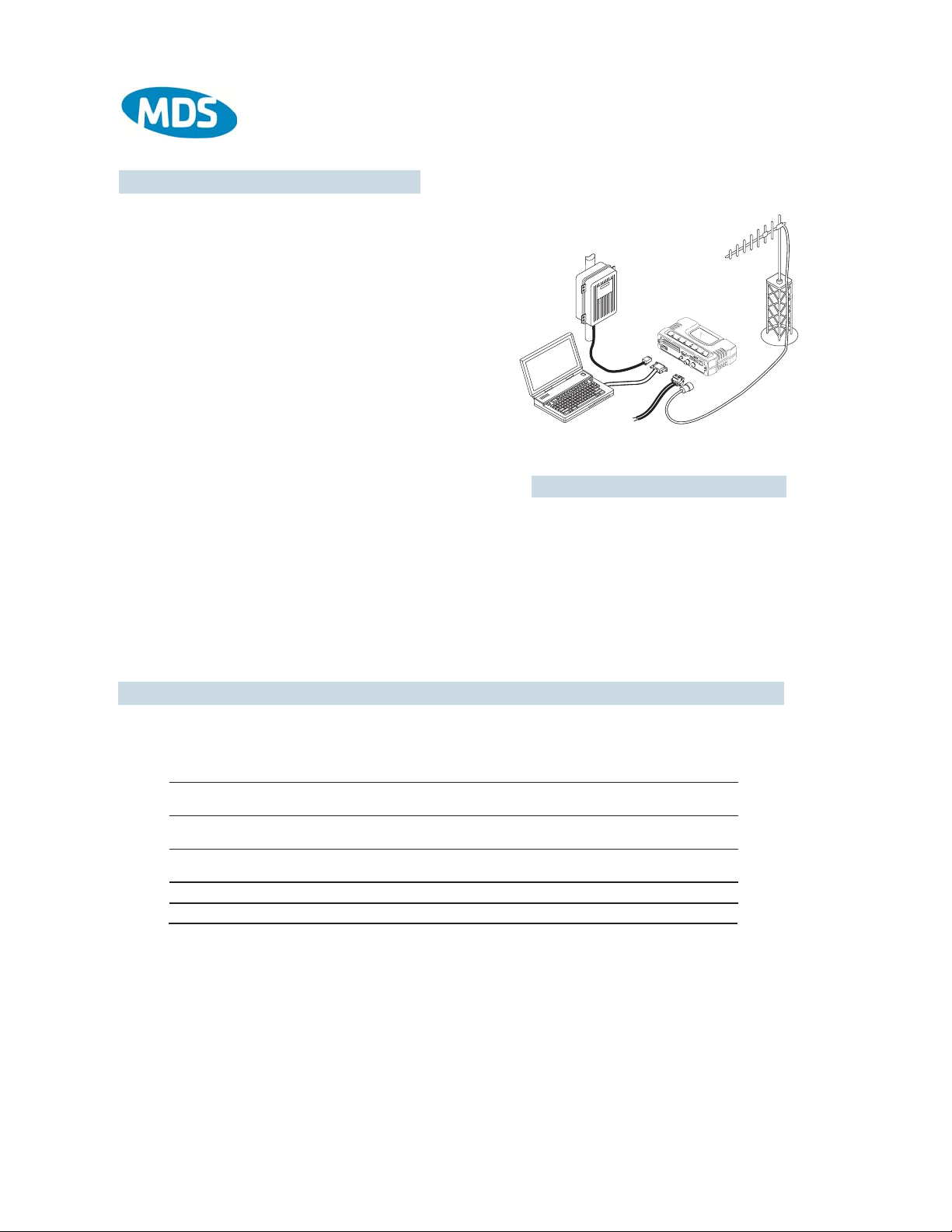
INSTALLATION SUMMARY
Step 1 – Mount the Transceiver
Step 2 – Install the Antenna
Step 3 – Measure & Connect Primary Power
Step 4 – Review the transceiver’s Configuration
Device Mode—Access Point, or Remote (Default)
Network Name—Unique name for each radio network.
Required for Remotes to associate with Access Point.
IP Address—Must be a unique number to allow for IP access
through the Ethernet Port.
NOTE: A unique IP address is essential to access the browser-based
Management System.
RF Output Power—Adjust as necessary for regulatory compliance.
(Default = 1 Watt /+30 dBm)
Password—Used for remote access and some Management System
features. (Default = admin)
Step 5 – Connect the Data Equipment
Connect the data equipment to data port(s):
• LAN—10BaseT Ethernet-compatible equipment:
Ethernet Hub (Straight-Through Cable); Ethernet Node (Crossover)
• COM1—Management System (Default); Serial (Alternate)
Step 6 – Check for Normal Operation
• Observe the transceiver LED status panel for the proper indications. In a normally operating system, the following LED indications
will be seen within 30 seconds of power-up:
PWR—Lights continuously LAN—On or blinks intermittently LINK— On or blinks intermittently (Remotes: if associated)
• Use PING command to test basic data link integrity between Access Point and Remotes.
• If the PING command is successful, connect the RTU/data equipment to the data port and verify normal operation.
• If the LINK LED on Remotes is not on after 20 to 30 seconds, the unit has failed to associate with the Access Point. It may be
necessary to reposition or redirect the radio’s antenna for better reception/signal strength.
• Check connected data equipment for normal operation
(10.5–30 Vdc)
DATA TERMINAL
EQUIPMENT OR
LAN/WAN
TRANSCEIVER
COMPUTER
W/TERMINAL
EMULATOR
POWER SUPPLY
13.8 VDC @ 580 mA (Max.)
(10.5–30 Vdc)
Negative Ground Only
TYPICAL INSTALLATION
ANTENNA
SYSTEM
LOW-LOSS FEEDLINE
BASIC CONFIGURA TION DEF AULTS
The Management System can be accessed through the COM1 Port using a terminal session on a PC. The basic items listed below,
along with many other parameters & tools can be accessed through this method. HTTP, Telnet access, and changing some parameters
are controlled by password.
ITEM MGT SYSTEM MENU
Device Mode Network Configuration
Unit Password Device Information
Network Name Network Configuration
IP Address Network Configuration
RF Output Power Radio Configuration
Detailed instructions for setting transceiver parameters are contained in Section 3 of this manual.
DEFAULT
Remote
admin
(lower case)
"Not Programmed"
192.168.1.1
+30 dBm (1.0 Watt)
VALUES/RANGE
• Remote
•Access Point
•1–8 alphanumeric characters
•Case-sensitive; can be mixed case
• 1–16 alphanumeric characters
• Case-sensitive; can be mixed case
Contact your Network Administrator
20–30 dBm @ 50Ω (0.1–1.0 Watt)
Page 3

TABLE OF CONTENTS
1 PRODUCT OVERVIEW AND APPLICATIONS .......... 1
1.1 PRODUCT DESCRIPTION................................................................................................... 3
1.1.1 Model Offerings .......................................................................................................................... 5
1.2 APPLICATIONS .................................................................................................................... 6
1.2.1 Wireless LAN .............................................................................................................................. 6
1.2.2 Point-to-Point LAN Extension .....................................................................................................6
1.2.3 Backhaul for Serial Radio Networks ...........................................................................................7
1.2.4 Multiple Protocols and/or Services ............................................................................................. 7
1.2.5 Wireless LAN with Mixed Services .............................................................................................8
1.2.6 Upgrading Older Wireless Network with
Serial Interfaces ....................................................................................................................................9
1.2.7 High-Speed Mobile Data ..........................................................................................................10
1.3 NETWORK DESIGN CONSIDERATIONS.......................................................................... 10
1.3.1 Extending Network Coverage with Repeaters .......................................................................... 10
1.3.2 Protected Network Operation using Multiple Access Points .....................................................12
1.3.3 Collocating Multiple Radio Networks ........................................................................................13
1.4 MDS CYBER SECURITY SUITE........................................................................................ 14
1.5 ACCESSORIES .................................................................................................................. 15
2 TABLETOP EVALUATION AND TEST SETUP ....... 19
2.1 OVERVIEW......................................................................................................................... 21
2.2 STEP 1 INSTALL THE ANTENNA CABLING ................................................................... 21
2.3 STEP 2 MEASURE & CONNECT THE PRIMARY POWER ............................................ 22
2.4 STEP 3 CONNECT PC TO THE TRANSCEIVER............................................................ 23
2.5 STEP 4 REVIEW TRANSCEIVER CONFIGURATION .................................................... 23
2.5.1 Getting Started ......................................................................................................................... 23
2.5.2 Procedure .................................................................................................................................23
2.5.3 Basic Configuration Defaults .................................................................................................... 23
MDS 05-4446A01, Rev. A MDS Mercury User’s Guide i
Page 4

ii
2.6 STEP 5 CONNECT LAN AND/OR SERIAL EQUIPMENT ............................................... 24
2.7 STEP 6 CHECK FOR NORMAL OPERATION................................................................. 26
3 EMBEDDED MANAGEMENT SYSTEM ................... 27
3.1 MS INTRODUCTION .......................................................................................................... 31
3.1.1 Differences in the User Interfaces ............................................................................................ 31
3.2 ACCESSING THE MENU SYSTEM ................................................................................... 33
3.2.1 Methods of Control ................................................................................................................... 34
3.2.2 PC Connection & Log In Procedures .......................................................................................34
3.2.3 Navigating the Menus ............................................................................................................... 39
3.3 BASIC DEVICE INFORMATION ......................................................................................... 40
3.3.1 Starting Information Screen ...................................................................................................... 40
3.3.2 Main Menu ................................................................................................................................ 41
3.3.3 Configuring Basic Device Parameters ...................................................................................... 42
3.4 CONFIGURING NETWORK PARAMETERS ..................................................................... 44
3.4.1 Network Configuration Menu ....................................................................................................44
3.4.2 IP Address Configuration Menu ................................................................................................ 46
3.4.3 Ethernet Port Configuration Menu ............................................................................................47
3.4.4 DHCP Server Configuration ..................................................................................................... 48
3.4.5 SNMP Agent Configuration ....................................................................................................... 50
3.5 RADIO CONFIGURATION.................................................................................................. 52
3.5.1 Radio Configuration Menu ...................................................................................................... 52
3.5.2 Mobile Data Configuration ........................................................................................................59
3.6 CONFIGURING THE SERIAL INTERFACES ..................................................................... 62
3.6.1 Overview ..................................................................................................................................62
3.6.2 Serial Data Port Configuration Menu ........................................................................................ 65
3.6.3 Configuring for UDP Mode ....................................................................................................... 66
3.6.4 Configuring for TCP Mode ........................................................................................................ 69
3.6.5 Configuring for PPP Mode ........................................................................................................ 72
3.6.6 IP-to-Serial Application Example ..............................................................................................73
3.6.7 Point-to-Point Serial-to-Serial Application Example ................................................................. 74
3.6.8 Point-to-Multipoint Serial-to-Serial Application Example .......................................................... 75
3.6.9 Mixed Modes ............................................................................................................................ 77
3.7 CYBER SECURITY CONFIGURATION ............................................................................. 79
3.7.1 Device Security ........................................................................................................................79
3.7.2 Wireless Security ...................................................................................................................... 81
MDS Mercury User’s Guide MDS 05-4446A01, Rev. A
Page 5

3.7.3 RADIUS Authentication ............................................................................................................ 83
3.7.4 RADIUS Configuration .............................................................................................................84
3.7.5 Certificate Management (Remote transceivers only) ............................................................... 85
3.8 PERFORMANCE VERIFICATION ...................................................................................... 86
3.8.1 Performance Information Menu ................................................................................................86
3.8.2 Network Performance Notes .................................................................................................... 97
3.9 MAINTENANCE................................................................................................................ 101
3.9.1 Reprogramming Menu ............................................................................................................ 102
3.9.2 Configuration Scripts Menu .................................................................................................... 107
3.9.3 Authorization Keys Menu ........................................................................................................ 116
3.9.4 Auto-Upgrade/Remote-Reboot Menu ..................................................................................... 116
3.9.5 Radio Test Menu ..................................................................................................................... 117
3.9.6 Ping Utility Menu .................................................................................................................... 119
3.9.7 Reset to Factory Defaults ....................................................................................................... 119
4 TROUBLESHOOTING AND
RADIO MEASUREMENTS .....................................119
4.1 TROUBLESHOOTING...................................................................................................... 123
4.1.1 Interpreting the Front Panel LEDs ..........................................................................................123
4.1.2 Troubleshooting Using the Embedded Management System ................................................ 124
4.1.3 Using Logged Operation Events ............................................................................................128
4.1.4 Alarm Conditions .................................................................................................................... 128
4.1.5 Correcting Alarm Conditions ...................................................................................................130
4.1.6 Logged Events .......................................................................................................................131
4.2 RADIO (RF) MEASUREMENTS ....................................................................................... 133
4.2.1 Antenna System SWR and Transmitter Power Output ........................................................... 134
4.2.2 Antenna Aiming ......................................................................................................................135
5 PLANNING A RADIO NETWORK .......................... 135
5.1 INSTALLATION PLANNING ............................................................................................. 139
5.1.1 General Requirements ........................................................................................................... 139
5.1.2 Site Selection .........................................................................................................................141
5.1.3 Terrain and Signal Strength ....................................................................................................141
5.1.4 Antenna & Feedline Selection ................................................................................................ 142
5.1.5 How Much Output Power Can be Used? ...............................................................................145
5.1.6 Conducting a Site Survey .......................................................................................................145
5.1.7 A Word About Radio Interference ...........................................................................................146
5.2 dBm-WATTS-VOLTS CONVERSION CHART .................................................................. 149
MDS 05-4446A01, Rev. A MDS Mercury User’s Guide iii
Page 6

iv
6 TECHNICAL REFERENCE ..................................... 149
6.1 DATA INTERFACE CONNECTORS ................................................................................. 153
6.1.1 LAN Port .................................................................................................................................153
6.1.2 USB Ports ............................................................................................................................... 154
6.1.3 COM1 Port .............................................................................................................................154
6.2 FUSE REPLACEMENT PROCEDURE ............................................................................ 155
6.3 TECHNICAL SPECIFICATIONS ....................................................................................... 156
6.4 CHANNEL HOP TABLE .................................................................................................... 159
6.5 SNMP USAGE NOTES..................................................................................................... 161
6.5.1 Overview ................................................................................................................................161
7 GLOSSARY OF TERMS & ABBREVIATIONS ....... 165
Copyright Notice
This publication is protected by U.S.A. copyright law. Copyright 2006, Microwave Data Systems,
Inc. All rights reserved.
ISO 9001 Registration
Microwave Data Systems adheres to the internationally-accepted ISO 9001 quality system standard.
To our Customers
We appreciate your patronage. You are our business. We promise to serve and anticipate your
needs. We will strive to give you solutions that are cost effective, innovative, reliable and of the
highest quality possible. We promise to build a relationship that is forthright and ethical, one that
builds confidence and trust.
Related Materials on the Internet
tion notes, firmware upgrades and other updated information is available on the MDS Web site at
www.microwavedata.com.
Data sheets, frequently asked questions, case studies, applica-
About Microwave Data Systems Inc.
Almost two decades ago, MDS began building radios for business-critical applications. Since then,
we ve installed nearly 100,000,000 radios in over 110 countries. To succeed, we overcame impassable terrain, brutal operating conditions and disparate, complex network configurations. We also
became experts in wireless communication standards and system applications worldwide. The
result of our efforts is that today, thousands of utilities around the world rely on MDS-based wireless networks to manage their most critical assets.
MDS Mercury User’s Guide MDS 05-4446A01, Rev. A
Page 7
The majority of MDS radios deployed since 1985 are still installed and performing within our customers’ wireless networks. That s because we design and manufacture our products in-house,
according to ISO 9001 which allows us to control and meet stringent global quality standards.
Thanks to our durable products and comprehensive solutions, MDS is the wireless leader in industrial automation including oil and gas production and transportation, water/wastewater treatment, supply and transportation, electric transmission and distribution and many other utility
applications. MDS is also at the forefront of wireless communications for private and public infrastructure and online transaction processing. Now is an exciting time for MDS and our customers
as we look forward to further demonstrating our abilities in new and emerging markets.
As your wireless needs change you can continue to expect more from MDS. We’ll always put the
performance of your network above all. Visit us at www.microwavedata.com for more information.
OPERATIONAL & SAFETY NOTICES
RF Exposure
CSA/
This product is pending approval for use in Class 1, Division 2, Groups A, B, C & D Hazardous Locations. Such locations are defined in Article 500 of the National Fire Protection Association (NFPA) publication NFPA 70 , otherwise
known as the National Electrical Code.
The transceiver has been recognized for use in these hazardous locations by the Canadian Standards Association
(CSA) which also issues the US mark of approval (CSA/
C22.2 No. 213-M1987.
CSA Conditions of Approval: The transceiver is not acceptable as a stand-alone unit for use in the hazardous locations
described above. It must either be mounted within another piece of equipment which is certified for hazardous
locations, or installed within guidelines, or conditions of approval, as set forth by the approving agencies. These
conditions of approval are as follows:
The transceiver must be mounted within a separate enclosure which is suitable for the intended application.
The antenna feedline, DC power cable and interface cable must be routed through conduit in accordance with the
National Electrical Code.
Installation, operation and maintenance of the transceiver should be in accordance with the transceiver’s installation
manual, and the National Electrical Code.
Notice
us
Professional installation required. The radio equipment described in this guide emits radio
frequency energy. Although the power level is low, the concentrated energy from a directional antenna may pose a health hazard. Do not allow people to come closer than 23 cm
(9 inches) to the antenna when the transmitter is operating in indoor or outdoor environments. More information on RF exposure is on the Internet at
www.fcc.gov/oet/info/documents/bulletins
US
). The CSA Certification is in accordance with CSA STD
.
Tampering or replacement with non-factory components may adversely affect the safe use of the transceiver in hazardous locations, and may void the approval.
A power connector with screw-type retaining screws as supplied by MDS must be used.
Do not disconnect equipment unless power has been switched off or the area is known to
be non-hazardous.
EXPLOSION
HAZARD!
MDS 05-4446A01, Rev. A MDS Mercury User’s Guide v
Refer to Articles 500 through 502 of the National Electrical Code (NFPA 70) for further
information on hazardous locations and approved Division 2 wiring methods.
Page 8

vi
FCC Part 15 Notices
The transceiver series complies with Part 15 of the FCC Rules. Operation is subject to the following two conditions:
(1) this device may not cause harmful interference, and (2) this device must accept any interference received, including
interference that may cause undesired operation. This device is specifically designed to be used under Section 15.247
of the FCC Rules and Regulations. Any unauthorized modification or changes to this device without the express
approval of Microwave Data Systems may void the user s authority to operate this device. Furthermore, the Mercury
Series is intended to be used only when installed in accordance with the instructions outlined in this manual. Failure
to comply with these instructions may also void the user s authority to operate this device.
Part 15 rules also require that the Effective Isotropic Radiated Power (EIRP) from an MDS Mercury Series installation
not exceed 36 dBm. Refer to 5.1.4 Antenna & Feedline Selection 140 on Page 137 for more information.
Industry Canada RSS Notices
Operation is subject to the following two conditions: (1) this device may not cause interference, and (2) this device
must accept any interference, including interference that may cause undesired operation of the device.
To reduce potential radio interference to other users, the antenna type and its gain should be chosen so that the Equivalent Isotropic Radiated Power (EIRP) is not more than that permitted for successful communication.
This device as been designed to operate with the antennas listed below, and having a maximum gain of 12 dB.
Antennas not included in this list or having a gain greater than 12 dB are strictly prohibited for use with this device.
The required antenna impedance is 50 ohms. Refer to Table 5-3 on Page 147 for a list of antennas acceptable for use
with this transceiver.
Manual Revision and Accuracy
This manual was prepared to cover a specific version of firmware code. Accordingly, some screens and features may
differ from the actual unit you are working with. While every reasonable effort has been made to ensure the accuracy
of this publication, product improvements may also result in minor differences between the manual and the product
shipped to you. If you have additional questions or need an exact specification for a product, please contact our Customer Service Team using the information at the back of this guide. In addition, manual updates can often be found on
the MDS Web site at www.microwavedata.com.
Environmental Information
The manufacture of this equipment has required the extraction and use of natural resources. Improper disposal may
contaminate the environment and present a health risk due to hazardous substances contained within. To avoid dissemination of these substances into our environment, and to limit the demand on natural resources, we encourage you to
use the appropriate recycling systems for disposal. These systems will reuse or recycle most of the materials found in
this equipment in a sound way. Please contact MDS or your supplier for more information on the proper disposal of
this equipment.
MDS Mercury User’s Guide MDS 05-4446A01, Rev. A
Page 9

PRODUCT OVERVIEW
1
1 Chapter Counter Reset Paragraph
Contents
1.1 PRODUCT DESCRIPTION ..................................................... 3
1.2 APPLICATIONS ....................................................................... 6
AND APPLICATIONS
1.1.1 Model Offerings ........................................................................ 5
1.2.1 Wireless LAN ........................................................................... 6
1.2.2 Point-to-Point LAN Extension .................................................. 6
1.2.3 Backhaul for Serial Radio Networks ........................................ 7
1.2.4 Multiple Protocols and/or Services ........................................... 7
1.2.5 Wireless LAN with Mixed Services ........................................... 8
1.2.6 Upgrading Older Wireless Network with
Serial Interfaces .................................................................................. 9
1.2.7 High-Speed Mobile Data .......................................................... 10
1.3 NETWORK DESIGN CONSIDERATIONS .............................. 10
1.3.1 Extending Network Coverage with Repeaters ......................... 10
1.3.2 Protected Network Operation using Multiple Access Points .... 12
1.3.3 Collocating Multiple Radio Networks ....................................... 13
1.4 MDS CYBER SECURITY SUITE............................................. 14
1.5 ACCESSORIES....................................................................... 15
MDS 05-4446A01, Rev. A MDS Mercury User’s Guide 1
Page 10

2 MDS Mercury User’s Guide MDS 05-4446A01, Rev. A
Page 11
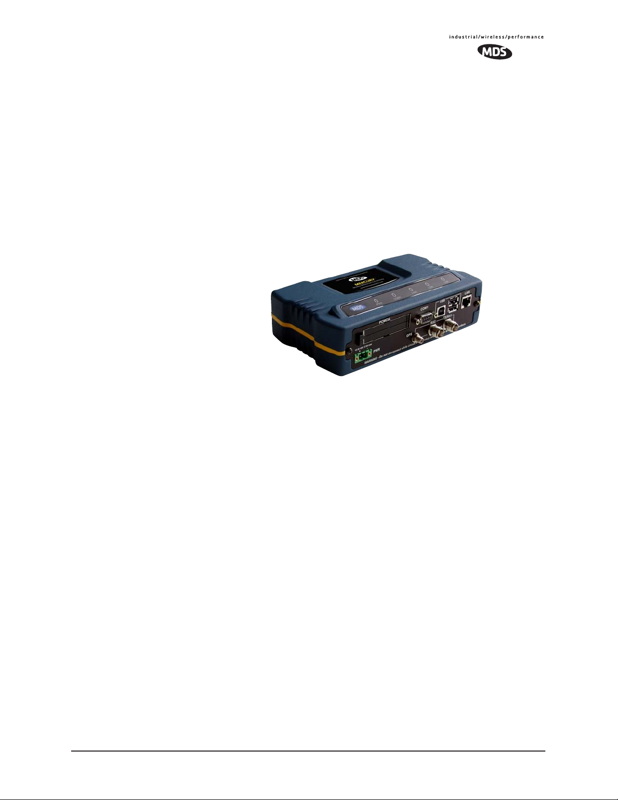
1.1 PRODUCT DESCRIPTION
The MDS Mercury 900
TM
transceiver provides an easy-to-install wireless local area network (WLAN) service with long range and secure
operation. It supports both Ethernet and serial data interface options at
over-the-air data speeds of up to 1.5 Mbps. The transceiver is ideally
suited for demanding applications in mobile or fixed environments,
where reliability and range are paramount.
The product is commonly used to convey text documents, graphics,
email, video, voice over IP (VoIP), and a variety of other application
data between mobile, fixed-point, and LAN-based entities.
Invisible place holder
Rugged Packaging
Simple Installation
Secure Operation
Figure 1-1. The MDS Mercury 900
TM
Transceiver
The transceiver is housed in a compact and rugged cast-aluminum case
that need only be protected from direct exposure to the weather. This
one enclosure contains all necessary components for radio operation and
data communications. The only user-serviceable component inside the
case is a fuse for the DC power input line.
Most installations employ an omni-directional antenna at the Access
Point (AP) location and mobile stations. Fixed Remote stations often
employ a directional antenna aimed at the AP. Regardless of the type
used, antennas are a vital part of the system and must be chosen and
installed correctly. Refer to INSTALLATION PLANNING on Page 139
for guidance on choosing suitable antennas and installation sites.
For basic services, simply connect an antenna, connect your Ethernet
LAN to the transceiver’s
port, apply primary power, set a few oper-
LAN
ating parameters, and you are done. No license is required for operation
in the U.S.A., Canada, and many other countries. Check requirements
for your region before placing the transceiver in service.
Data network security is a vital issue in today's wireless world. The Mercury Transceiver provides multiple tools to help you build a network
that minimizes the risk of eavesdropping and unauthorized access. Some
are inherent in the radio's operation, such as the use of 900 MHz
spread-spectrum transmissions; others include data encryption, en-
MDS 05-4446A01, Rev. A MDS Mercury User’s Guide 3
Page 12

abling/disabling remote access channels, and password protection.
Remember, security is not a one-step process that can simply be turned
on and forgotten. It must be practiced and enforced at multiple levels,
24 hours-a-day and 7 days-a-week. See “MDS CYBER SECURITY
SUITE” on Page 14 for more information about the transceiver’s secu-
rity tools.
Robust Radio
Operation
Flexible Services
Flexible
Management
The transceiver is designed for operation in the license-free 900 MHz
Industrial, Scientific, and Medical (ISM) band. It can provide reliable
communications at distances up to 25 miles (40 km) in fixed-site applications over favorable terrain, even in the presence of weak signals or
interference.
Mobile range depends on many factors, including terrain, building density, antenna gain, and speed of travel. The unit is designed for successful application in a variety of mobile environments, and offers the
best combination of range, speed and robustness available in an industrial wireless package today. By using multiple Access Points, a network
can be created that provides consistent, reliable coverage over a large
metropolitan area.
Users with a mix of equipment having Ethernet and serial data interfaces
can accommodate this equipment through the use of a Remote Dual
Gateway. This flexibility allows the transceiver to provide services in
data networks that are being migrated from legacy serial/EIA-232-based
hardware to the faster and more easily interfaced Ethernet world.
Configuration, commissioning, troubleshooting and other maintenance
activities can be done locally or remotely. Four different modes of
access are available: local RS-232 console, local or remote IP access
(via Telnet or SSH), web browser (HTTP, HTTPS), and SNMP
(v1/v2/v3).
The text-based interfaces (RS-232 console, Telnet, and SSH) are implemented in the form of easy-to-follow menus, and the terminal server
configuration includes a wizard to help you set up the units correctly.
Transceiver
Features
The transceiver’s design makes the installation and configuration easy,
while allowing for future changes.
• Long Range—Up to 25 miles (40 km) in line-of-sight conditions. Repeater stations may be used to extend the operational
range. (Refer to Page 158 for more detailed information on
range.)
• Industrial-Grade Product—Extended temperature range for
trouble-free operation in extreme environments
• Robust Radio Communications—Designed to operate in dense,
high-interference environments
4 MDS Mercury User’s Guide MDS 05-4446A01, Rev. A
Page 13

• Robust Network Security—Prevents common attack schemes
and hardware from gaining access or control of network. Common attack events logged and reported by alarms.
• High Speed—1.5 Mbps is over 100-times faster than 9.6 kbps
radios.
• Plug-and-Play Connectivity—Ethernet bridge configuration
option requires minimal setup
• Serial Ports—Gateway for serial-based equipment to IP/Ethernet networks with embedded terminal server. Site-to-site configurations are also possible.
• Single hardware package provides configuration as Access
Point or Remote
1.1.1 Model Offerings
The transceiver comes in two primary models—Access Point and
Remote. Three types of Remote Gateways are available—the Ethernet
Bridge, the Serial Gateway, and the Dual Gateway supporting both
IP/Ethernet and serial services. Table 1-1 summaries the different interface abilities for each type.
A unit can be configured in the field to operate as an Access Point or as
a Remote with some restrictions. Only the Dual Gateway Remote units
can be reconfigured as an Access Point. Ethernet Bridge and a Serial
Gateway Remotes cannot be reconfigured as Access Point unless they
are first upgraded to Dual Gateway type. This is accomplished with an
“Authorization Key” purchased from the factory. Each one of these
individual software keys is associated with the serial number of the corresponding unit.
Table 1-1. Transceiver Models and Data Interface Services
Model Type
3
Access Point
Remote… Ethernet
NOTES
1. Provides access to the embedded Management System on all units.
2. Can be upgraded to Dual Gateway with an Authorization Key.
3. Can be configured as an Access Point or Dual Gateway through the embedded Management System.
N/A Yes Yes
2
Bridge
Serial
Gateway
Dual Gateway
2
3
1
LAN
Yes No
No Yes
Yes Yes
COM1
1
MDS 05-4446A01, Rev. A MDS Mercury User’s Guide 5
Page 14
1.2 APPLICATIONS
R
The following sections provide illustrations of typical transceiver installations. This is meant as an overview only. It is recommended that a network manager be involved in all installation planning activities.
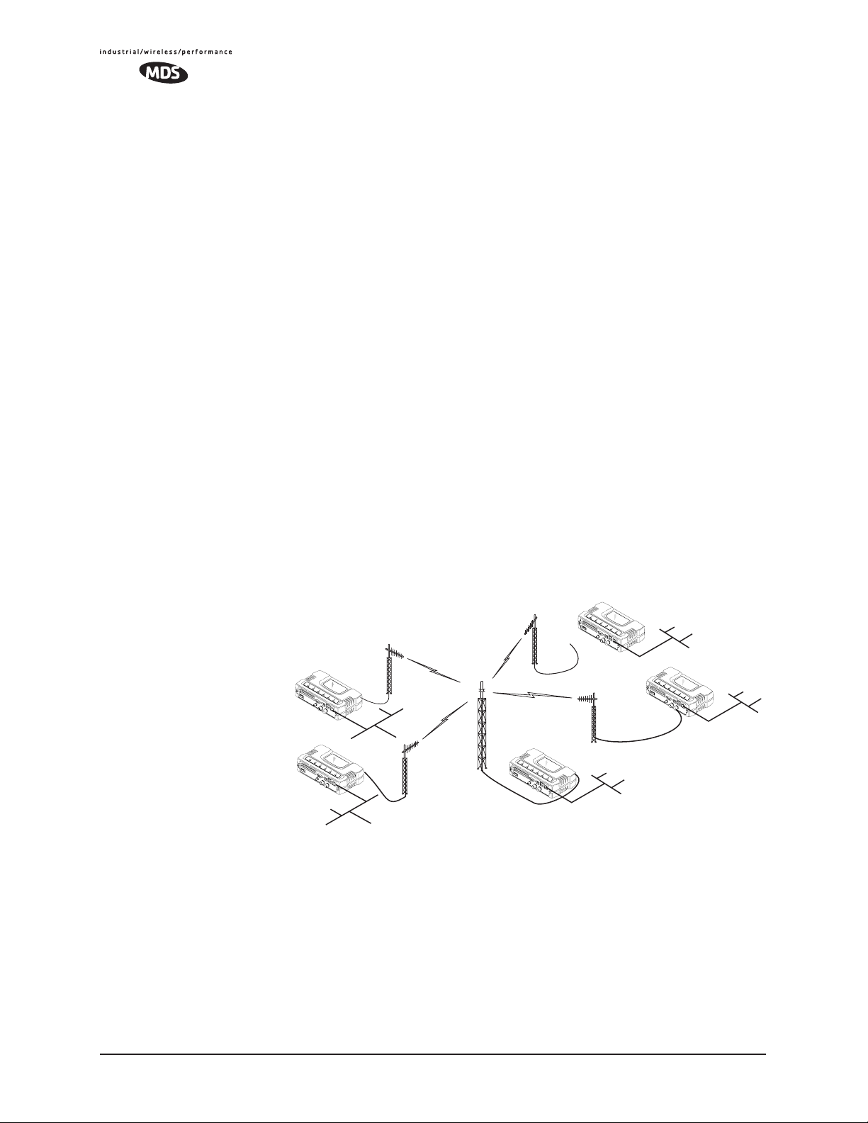
1.2.1 Wireless LAN
The wireless LAN is the most common application of the transceiver. It
consists of a central control station (Access Point) and one or more associated Remote units, as shown in Figure 1-2 on Page 6. A LAN provides
communications between a central WAN/LAN and remote Ethernet
segments. The operation of the radio system is transparent to the computer equipment connected to the transceiver.
The Access Point is positioned at a location from which it can communicate with all of the Remote units in the system. Commonly, this is a
high location on top of a building or communications tower. Messages
are exchanged at the Ethernet level. This includes all types of IP traffic.
A Remote transceiver can only talk over-the-air to an Access Point unit
(AP). Peer-to-peer communications between Remotes can only take
place indirectly via the AP. In the same fashion, an AP can only talk
over-the-air to associated Remote units. Exception: Two APs can communicate with each other “off-the-air” through their Ethernet connectors
using a common LAN/WAN.
Remote
Remote
LAN
LAN
Invisible place holder
Access Point
emote
LAN
Remote
LAN
WAN/LAN
Figure 1-2. Typical Wireless LAN
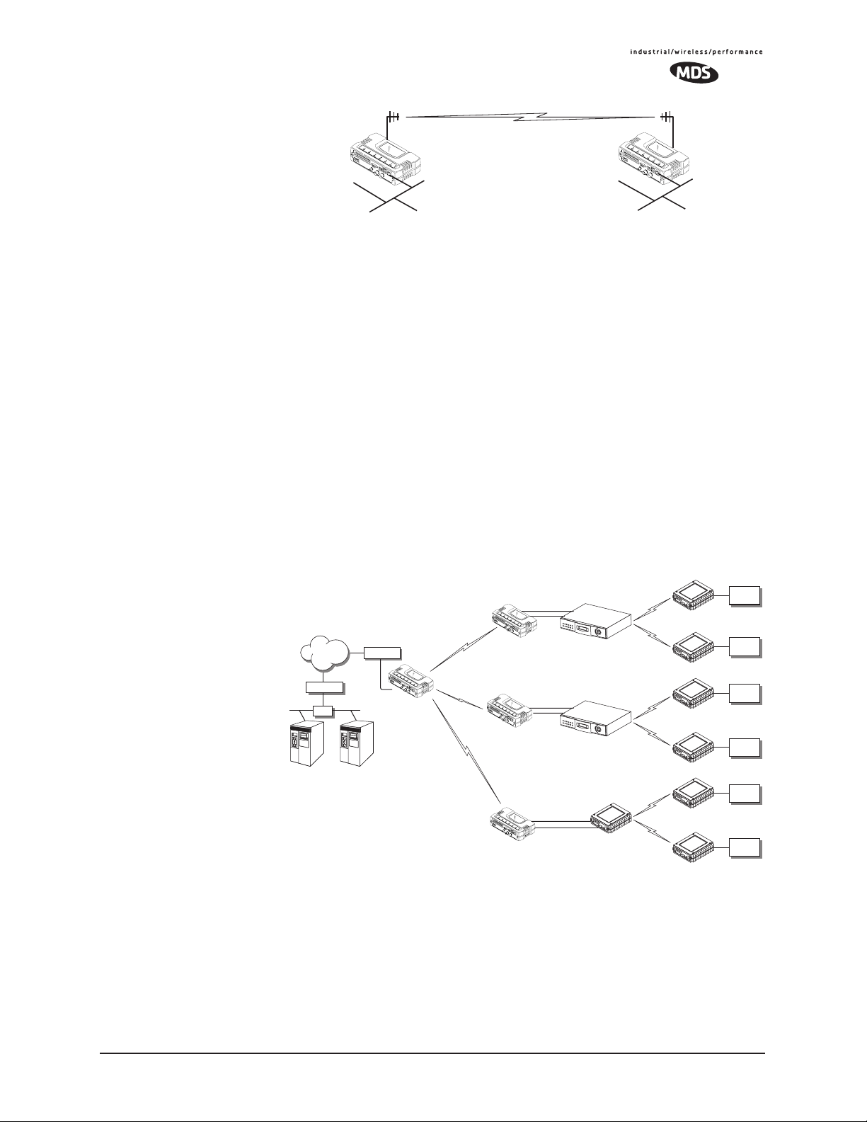
1.2.2 Point-to-Point LAN Extension
A point-to-point configuration (Figure 1-3) is a simple arrangement
consisting of an Access Point and a Remote unit. This provides a communications link for the transfer of data between two locations.
6 MDS Mercury User’s Guide MDS 05-4446A01, Rev. A
Page 15
Invisible place holder
Access Point
LAN/WAN
Remote
LAN
Figure 1-3. Typical Point-to-Point Link
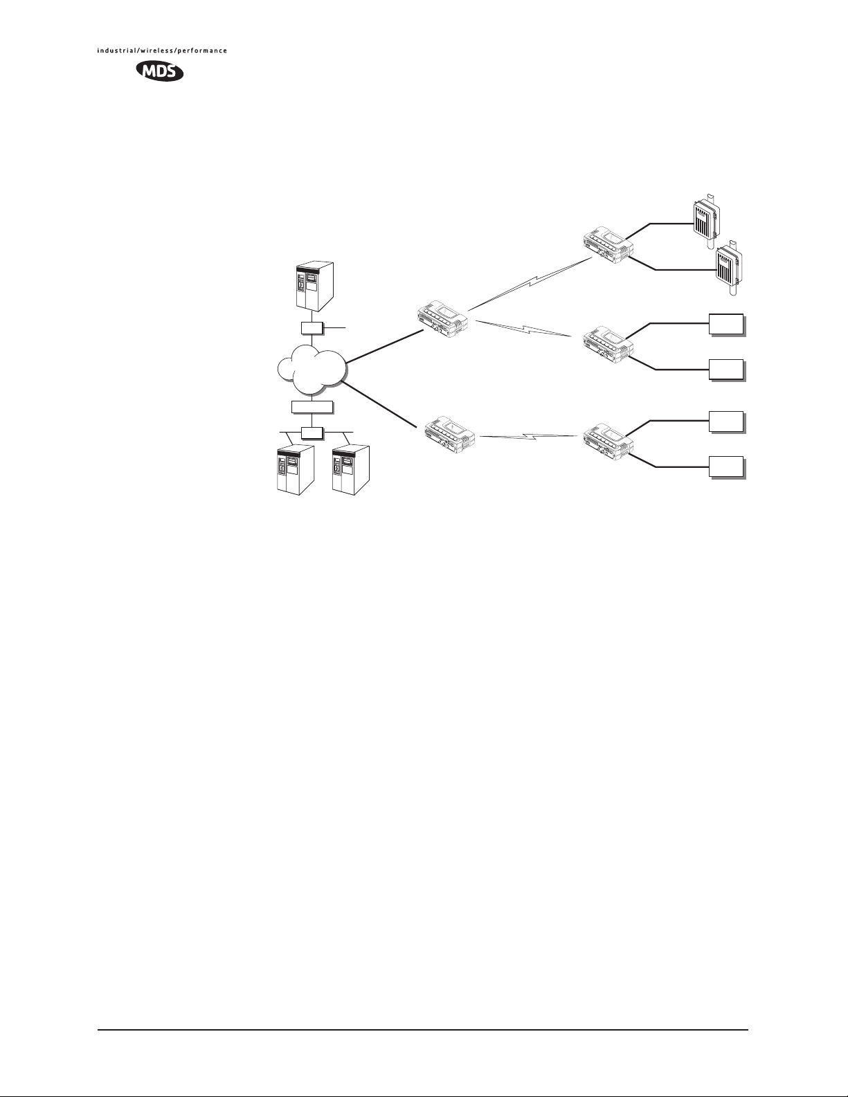
1.2.3 Backhaul for Serial Radio Networks
One of the primary design features of the transceiver is to provide a path
for serial devices to migrate to IP/Ethernet. Many radio networks in
operation today still rely on serial networks at data rates of 9600 bps or
less. These networks can use the transceiver as a means to continue
using the serial service, while allowing the rest of the infrastructure to
migrate to an IP format.
A Remote transceiver using one serial port for the data stream, and the
other for network-wide diagnostics can support operational radio networks built with MDS serial-based radios, such as MDS x790/x710,
MDS TransNET and others. In the case of radios using a single port for
data and diagnostics, the capabilities are doubled. The data streams are
delivered to an IP socket in an application, or in serial format using the
Access Point.
Invisible place holder
Serial
Device
Serial
Device
Serial
Device
Serial
Device
Serial
Device
Serial
Device
NETWORK
ROUTER
NMS Control
Point
HUB
ROUTER
SCADA Host
Modbus/IP
Access Point
Remote Serial
Remote Serial
Remote Serial
Diagnostics
Data
Diagnostics
Data
Diagnostics
Data
MDS 4790
Master
MDS 9790
Master
MDS 9810
MDS 4710 Remote
MDS 4710 Remote
MDS 9710 Remote
MDS 9710 Remote
MDS 9810 Remote
Master
MDS 9810 Remote
Figure 1-4. Backhaul Network
1.2.4 Multiple Protocols and/or Services
Prior to the introduction of EThernet/IP-based radios, two radios were
often used to service two different types of devices (typically connected
to different SCADA hosts). A Mercury radio provides this functionality
using a single remote unit. Each of the two serial ports can be connected
MDS 05-4446A01, Rev. A MDS Mercury User’s Guide 7
Page 16
via IP to different SCADA hosts, transporting different (or the same)
protocols. Both data streams are completely independent and the transceiver provides seamless simultaneous operation as shown in
Figure 1-5.
Invisible place holder
RTU
EIA-232
Flow Meter
EIA-232
EIA-232
EIA-232
EIA-232
EIA-232
Serial
Device
Serial
Device
Serial
Device
Serial
Device
NETview
HUB
HUB
WAN
ROUTER
HUB
HUB
SCADA Host
Modbus/IP
SCADA Host
Total Flow
Remote Serial
Remote Serial
Access Point
Remote Serial
Access Point
Figure 1-5. Multiple Protocol Network
By using a single radio, the cost of deployment is cut in half. Beyond
requiring only one radio instead of two, the biggest cost reduction comes
from using half of the required infrastructure at the remote site: one
antenna, one feedline, one lightning protector and ancillary hardware.
Other cost reductions come from the system as a whole, such as reduced
management requirements. And above all, the potential for future applications that run over Ethernet and IP, such as video for remote surveillance.
1.2.5 Wireless LAN with Mixed Services
The transceiver is an excellent solution for a long-range industrial wireless LAN. It offers several advantages over commercial solutions—primarily improved performance over extended distances. The rugged
construction of the radio and its extended temperature range make it an
ideal solution even in harsh locations. In extreme environments, a
simple NEMA enclosure is sufficient to house the unit.
The transceiver trades higher speed for longer range. Commercial
802.11a/b/g solutions are designed to provide service to relatively small
areas such as offices, warehouses and homes. They provide high data
rates but have limited range. The Mercury transmits at a higher power
level, uses a different frequency band, has higher sensitivity, and a narrower channel to concentrate the radio energy and reach farther distances. It is designed for industrial operation from the ground up.
8 MDS Mercury User’s Guide MDS 05-4446A01, Rev. A
Page 17
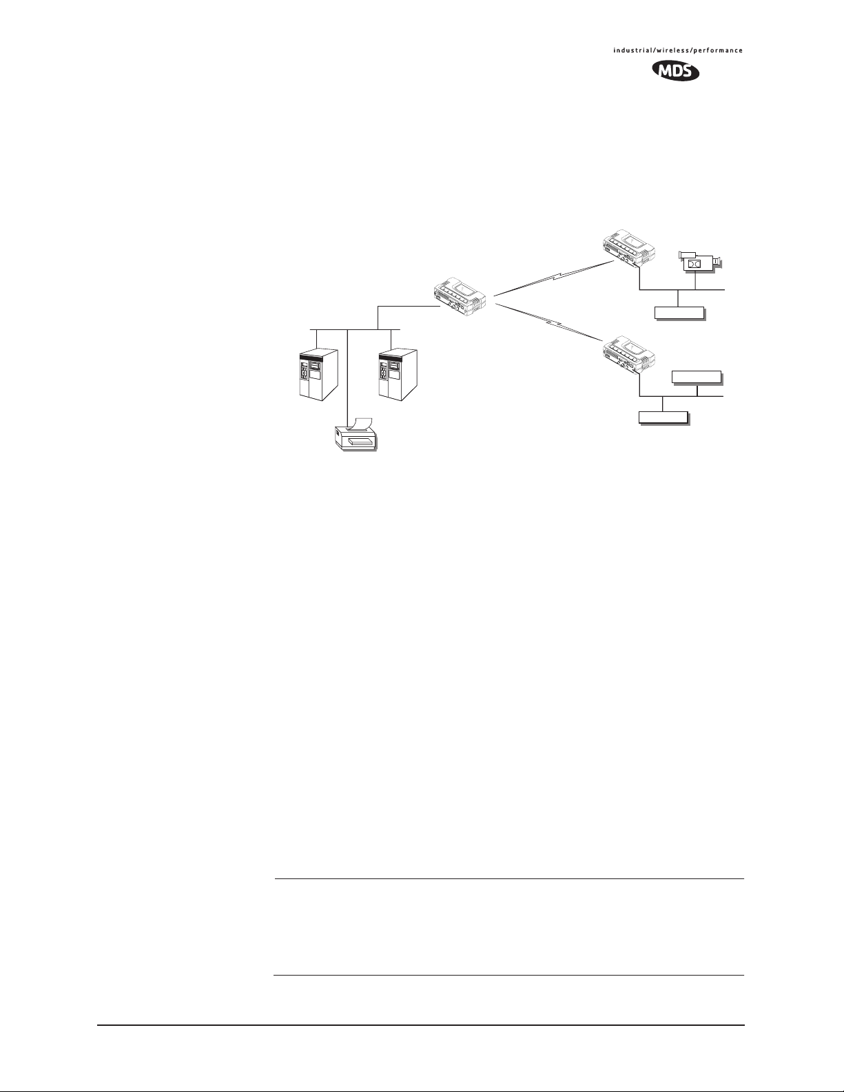
IP-based devices that may be used with the transceiver include a new
breed of more powerful Remote Terminal Units (RTUs) and Programmable Logic Controllers (PLCs). These, as well as other devices, may
be used in applications ranging from SCADA/telemetry monitoring,
web-based video, security monitoring, and voice over IP. Figure 1-6
shows a typical wireless IP network.
Invisible place holder
Remote Bridge
IP Camera
IP/Ethernet
IP/Ethernet
IP/Ethernet
NMS Control
Point
SCADA Host
Modbus/IP
Printer
Access Point
Remote Bridge
Figure 1-6. Extended-Range LAN with Mixed Applications
1.2.6 Upgrading Older Wireless Network with
Serial Interfaces
Millions of wireless data products have been sold in the last two decades
for licensed and license-free operation, many of them manufactured by
Microwave Data Systems. There are several ways that these systems can
benefit from incorporating Mercury equipment. The chief advantages
are interface flexibility (serial and Ethernet in one unit), and higher data
throughput. By taking advantage of its built-in serial and Ethernet interfaces, the transceiver is well suited to replace leased lines, dial-up lines,
or existing MAS 900 MHz data transceivers.
Replacing Legacy Wireless Products
In most cases, legacy radio transceivers supporting serial-interface
equipment can be replaced with Mercury transceivers. Legacy equipment can be connected to the transceiver through the
DB-25 to DB-9 cable wired for EIA-232 signaling. The
COM1 port with a
COM1 port sup-
ports all standard EIA-232 signaling and acts as a data-terminal equipment device (DTE).
NOTE: Several previous MDS-brand products had non-standard
signal lines on their interface connectors (for example, to
control sleep functions and alarm lines). These special functions are not provided nor supported by the transceiver.
Consult equipment manuals for complete pinout information.
MDS 05-4446A01, Rev. A MDS Mercury User’s Guide 9
Page 18

Supplement legacy wireless network with IP services
The Mercury Dual Gateway model can support up to two serial devices
and one Ethernet connection at the same time. The serial interface
(COM1) operates in two different modes: Connectionless UDP and connection-orientated TCP.
In the UDP mode, the transceiver supports point-to-multipoint
serial-port to serial-port connectivity. In the TCP mode, it supports
point-to-point Ethernet/IP to serial port connectivity.
For further details on the transceiver’s Serial Gateway interface modes,
see “CONFIGURING THE SERIAL INTERFACES” on Page 62.
1.2.7 High-Speed Mobile Data
Mercury transceivers support high-speed data communications in a
mobile environment. Remote radios roam between different Access
Points, providing seamless transitions and continuous coverage. For
additional information on configuring a mobile network, refer to Mobile
Data Configuration on Page 59.
1.3 NETWORK DESIGN
CONSIDERATIONS
1.3.1 Extending Network Coverage with Repeaters
What is a Repeater System?
A repeater works by re-transmitting data from outlying remote sites to
the Access Point and vice-versa. It introduces some additional
end-to-end transmission delay but provides longer-range connectivity.
In some geographical areas, obstacles can make communications difficult. These obstacles are commonly large buildings, hills, or dense
foliage. These obstacles can often be overcome with a repeater station.
Option 1—Using two transceivers to form a repeater station
(back-to-back repeater)
Although the range between fixed transceivers can be up to 40 km (25
miles) over favorable terrain, it is possible to extend the range considerably by connecting two units together at one site in a “back-to-back”
fashion to form a repeater, as shown in Figure 1-7. This arrangement
should be used whenever the objective is to utilize the maximum range
between stations. In this case, using high-gain Yagi antennas at each
location will provide more reliable communications than their counterparts—omnidirectional antennas.
10 MDS Mercury User’s Guide MDS 05-4446A01, Rev. A
Page 19
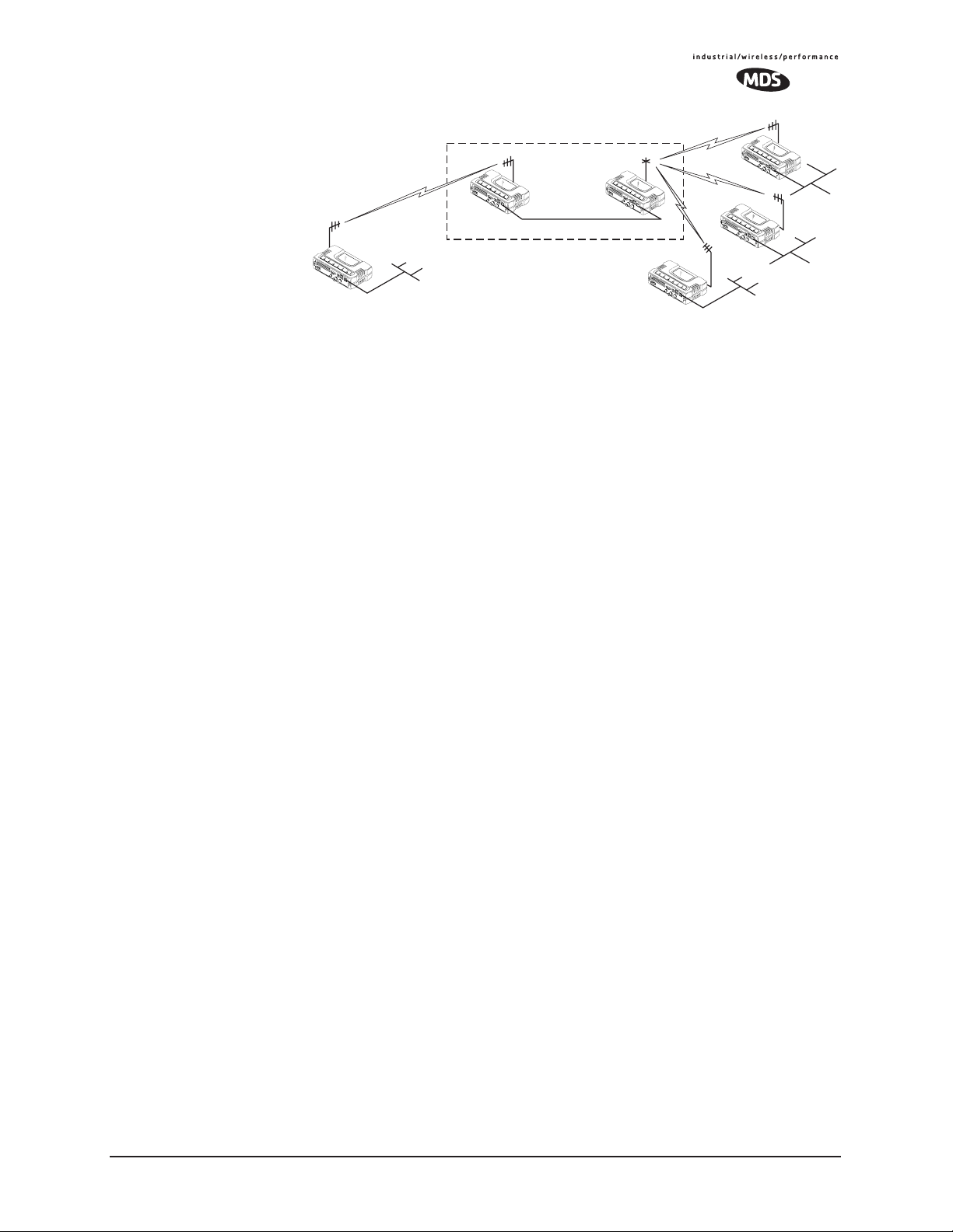
Invisible place holder
Overview
Remote
LAN
Remote
LAN
POINT-TO-POINT LINK
Access Point
LAN/WAN
Remote
REPEATER
Access
Point
Ethernet
Crossover Cable
Remote
LAN
Figure 1-7. Typical LAN with a Repeater Link
Two transceivers may be connected “back-to-back” through the LAN
Ports to form a repeater station. (The cable must be a “cross-over”
Ethernet cable for this to work). This configuration is sometimes
required in a network that includes a distant Remote that would otherwise be unable to communicate directly with the Access Point station
due to distance or terrain.
The geographic location of a repeater station is especially important. A
site must be chosen that allows good communication with both the
Access Point and the outlying Remote site. This is often on top of a hill,
building, or other elevated terrain from which both sites can be “seen”
by the repeater station antennas. A detailed discussion on the effects of
terrain is given in Section 5.1.2, Site Selection (beginning on Page 140).
The following paragraphs contain specific requirements for repeater
systems.
Antennas Two antennas are required at this type of repeater station—one for each
radio. Measures must be taken to minimize the chance of interference
between these antennas. One effective technique for limiting interference is to employ vertical separation. In this arrangement, assuming
both are vertically polarized, one antenna is mounted directly over the
other, separated by at least 10 feet (3 Meters). This takes advantage of
the minimal radiation exhibited by most antennas directly above and
below their driven elements.
Another interference reduction technique is to cross-polarize the
repeater antennas. If one antenna is mounted for polarization in the vertical plane, and the other in the horizontal plane, an additional 20 dB of
attenuation can be achieved. (Remember that the corresponding stations
should use the same antenna orientation when cross-polarization is
used.)
Network Name The two radios that are wired together at the repeater site must have dif-
ferent network names. To set or view the network names, see “STEP 3—
CONNECT PC TO THE TRANSCEIVER” on Page 22 for details.
MDS 05-4446A01, Rev. A MDS Mercury User’s Guide 11
Page 20
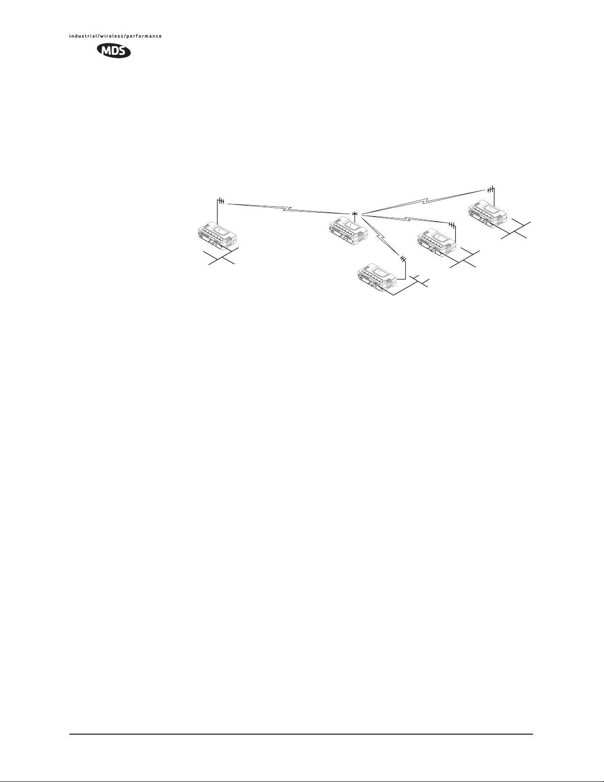
Option 2—Using the AP as a Store-and-Forward Packet
Repeater
A wireless network can be extended through the use of an alternate
arrangement using the Access Point as a repeater to re-transmit the signals of all stations in the network. The repeater is a standard transceiver
configured as an Access Point, and operating in Store and Forward
mode. (See Figure 1-8.)
Invisible place holder
Remote
LAN/WAN
Remote
Access Point
REPEATER
Remote
Remote
LAN
LAN
LAN
Figure 1-8. Typical network with store-and-forward repeater
As with the conventional repeater described in Option 1 above, the location of a store and forward repeater is also important. A site must be
chosen that allows good communication with both the Access Point and
the outlying Remote site. This can be on the top of a hill, building, or
other elevated terrain from which all sites can be “seen” by the repeater
station antenna. A detailed discussion on the effects of terrain is given
in Section 5.1.2, Site Selection (beginning on Page 140)
1.3.2 Protected Network Operation using Multiple
Access Points
Although MDS transceivers have a very robust design and have undergone intensive testing before being shipped, it is possible for isolated
failures to occur. In mission-critical applications, down time can be virtually eliminated by using some, or all, of the following configurations:
In a point-to-multipoint scenario, the Access Point services multiple
remotes. A problem in the Access Point will have an effect on all
remotes, since none will have access to the network. When operation of
the network does not tolerate any down time, it is possible to set up a
protected configuration for the Access Point to greatly reduce the possibility of this occurrence.
Two or more Access Points can be configured with the same Network
Name and kept active simultaneously, each with its own independent
antenna. In this scenario, Remotes will associate with either one of the
available Access Points. In case of a failure of one of the AP’s the
Remotes will quickly associate with another of the remaining Access
Points re-establishing connectivity to the end devices.
12 MDS Mercury User’s Guide MDS 05-4446A01, Rev. A
Page 21

The Access Points are unaware of the existence of the other AP’s.
Because the hopping algorithm uses both the Network Name and the
Wireless MAC address of the AP to generate the hopping pattern, multiple AP’s can coexist—even if they use the same network name. The
collocated AP’s will be using different hopping patterns and frequencies
the great majority of the time. Although some data collisions will occur,
the wireless-MAC is built to tolerate and recover from such occurrences
with minimal degradation.
1.3.3 Collocating Multiple Radio Networks
Many networks can operate in relatively close physical proximity to one
another provided reasonable measures are taken to assure the radio
signal of one Access Point is not directed at the antenna of the second
Access Point.
The Network Name and the association process
The Network Name is the foundation for building individual radio networks. It is part of a beacon signal broadcast by the Access Point (AP)
to any Remote units with the same Network Name. Remotes that join the
network are referred to as being “associated” with the Access Point unit.
Co-Location for
Multiple Networks
Multiple APs with the same Network Name should be used with care.
Using the same Network Name in multiple APs may result in Remotes
associating with undesired APs and preventing data exchange from
occurring as planned.
The use of a different Network Name does not guarantee an interference-free system. It does however, assure that only data destined for a
unique network is passed through to that network.
It may be desirable to co-locate Access Points at one location to take
advantage of an excellent or premium location that can serve two independent networks. Each network should have unique Network Name
and each AP unit’s antenna should be provided as much vertical separation as is practical to minimize RFI.
NOTE: All transceivers are shipped with the Network Name set to
“Not Programmed.” The Network Name must be programmed
in order to pass data and begin normal operations.
Can radio frequency interference (RFI) disrupt my wireless
network?
When multiple radio networks operate in close physical proximity to
other wireless networks, individual units may not operate reliably under
weak signal conditions and may be influenced by strong radio signals in
adjacent bands. This radio frequency interference cannot be predicted
with certainty, and can only be determined by experimentation. If you
need to co-locate two units, start by using the largest possible vertical
MDS 05-4446A01, Rev. A MDS Mercury User’s Guide 13
Page 22

antenna separation between the two AP antennas on the same support
structure. If that does not work, consult with your factory representative
about other techniques for controlling radio frequency interference
between the radios. (See “A Word About Radio Interference” on
Page 145 for more details.)
1.4 MDS CYBER SECURITY SUITE
Today the operation and management of an enterprise is becoming
increasing dependent on electronic information flow. An accompanying
concern becomes the cyber security of the communication infrastructure
and the security of the data itself.
The transceiver is capable of dealing with many common security
issues. Table 1-2 profiles security risks and how the transceiver provides a solution for minimizing vulnerability.
Table 1-2. Security Risk Management
Security Vulnerability MDS Cyber Security Solution
Unauthorized access to the backbone
network through a foreign remote radio
“Rogue” AP, where a foreign AP takes
control of some or all remote radios and
thus remote devices
Dictionary attacks, where a hacker runs a
program that sequentially tries to break a
password.
Denial of service, where Remote radios
could be reconfigured with bad
parameters bringing the network down.
Airsnort and other war-driving hackers in
parking lots, etc.
• 802.1x RADIUS authentication
• Approved Remotes List (local)
Only those remotes included in the
AP list will associate
• 802.1x RADIUS authentication
• Approved AP List
A remote will only associate to those
AP included in its local authorized
list of AP
• Failed-login lockdown
After 3 tries, the transceiver ignores
login requests for 5 minutes. Critical
event reports (traps) are generated
as well.
•Remote login with SSH or HTTPS
•Local console login
•Disabled HTTP & Telnet to allow
only local management services
•900 MHz operation is not
interoperable with standard 802.11b
wireless cards
•The transceiver cannot be put in a
promiscuous mode
•Proprietary data framing
Eavesdropping, intercepting messages
•AES-128 encryption
•RC4-128 encryption
Key cracking software
14 MDS Mercury User’s Guide MDS 05-4446A01, Rev. A
• Automatic Rotating Key algorithm
Page 23

Table 1-2. Security Risk Management
Security Vulnerability MDS Cyber Security Solution
Replaying messages
• Automatic Rotating Key algorithm
Unprotected access to configuration via
SNMPv1
Intrusion detection
•Implement SNMPv3 secure
operation
• Provides early warning via SNMP
through critical event reports
(unauthorized, logging attempts,
etc.)
• Unauthorized AP MAC address
detected at Remote
• Unauthorized Remote MAC
address detected at AP
• Login attempt limit exceeded
(Accessed via: Telnet, HTTP, or
local)
• Successful login/logout
(Accessed via: Telnet, HTTP, or
local)
1.5 ACCESSORIES
The transceiver can be used with one or more of the accessories listed in
Table 1-3. Contact the factory for ordering details.
Table 1-3. Accessories
Accessory Description MDS Part No.
AC Power
Adapter Kit
OmniDirectional
Antennas
Yagi Antenna
(Directional)
GPS Receiving
Antenna
(Powered)
TNC Male-to-N
Female Adapter
TNC Male-to-N
Female Adapter
Cable
Ethernet RJ-45
Crossover
Cable (CAT5)
A small power supply module designed for
continuous service. UL approved. Input:
120/220; Output: 13.8 Vdc @ 2.5 A
Rugged antennas well suited for use at Access
Point installations. Consult with your factory
Sales Representative for details
Rugged antennas well suited for use at Remote
installations. Consult with your factory Sales
Representative for details.
Attaches to GPS coaxial connector on front
panel of the transceiver. One popular type is the
Antenna Specialists K721GPS Amplified
Antenna.
One-piece RF adaptor plug. 97-1677A161
Short length of coaxial cable used to connect
the radio’s TNC antenna connector to a Type N
commonly used on large diameter coaxial
cables.
Cable assembly used to cross-connect the
Ethernet ports of two transceivers used in a
repeater configuration.
(Cable length ≈ 3 ft./1M)
01-3682A02
Call factory
Call factory
Call factory
97-1677A159
(3 ft./1m)
97-1677A160
(6 ft./1.8m)
97-1870A21
MDS 05-4446A01, Rev. A MDS Mercury User’s Guide 15
Page 24

Table 1-3. Accessories (Continued)
Accessory Description MDS Part No.
2-Pin Power
Plug
Ethernet RJ-45
Straight-thru
Cable (CAT5)
EIA-232
Shielded Data
Cable
EIA-232
Shielded Data
Cable
Fuse Small, board-mounted fuse used to protect
Flat-Surface
Mounting
Brackets &
Screws
DIN Rail
Mounting
Bracket
COM1 Interface
Adapter
Bandpass Filter Antenna system filter that helps eliminate
Ethernet Surge
Suppressor
Mates with power connector on transceiver.
Screw terminals provided for wires, threaded
locking screws to prevent accidental disconnect.
Cable assembly used to connect an Ethernet
device to the transceiver. Both ends of the cable
are wired identically.
(Cable length ≈ 3 ft./1M)
Shielded cable terminated with a DB-25 male
connector on one end, and a DB-9 female on the
other end. Two lengths available (see part
numbers at right).
Shielded cable terminated with a DB-9 male
connector on one end, and a DB-9 female on the
other end, 6 ft./1.8m long.
against over-current conditions.
Brackets: 2˝ x 3˝ plates designed to be screwed
onto the bottom of the unit for surface-mounting
the radio.
Screws: 6-32/1/4˝ with locking adhesive.
(Industry Standard MS 51957-26)
Bracket used to mount the transceiver to
standard 35 mm DIN rails commonly found in
equipment cabinets and panels.
DB-25(F) to DB-9(M) shielded cable assembly
(6 ft./1.8 m) for connection of equipment or other
EIA-232 serial devices previously connected to
“legacy” units. (Consult factory for other lengths
and variations.)
interference from nearby paging transmitters.
Surge suppressor for protection of Ethernet port
against lightning.
73-1194A39
97-1870A20
97-3035L06
(6 ft./1.8m)
97-3035L15
(15 ft./4.6m)
97-1971A03
29-1784A03
82-1753-A01
70-2620-A01
03-4022A02
97-3035A06
20-2822A02
29-4018A01
16 MDS Mercury User’s Guide MDS 05-4446A01, Rev. A
Page 25

MDS 05-4446A01, Rev. A MDS Mercury User’s Guide 17
Page 26

18 MDS Mercury User’s Guide MDS 05-4446A01, Rev. A
Page 27

TABLETOP EVALUATION
2
2 Chapter Counter Reset Paragraph
Contents
2.1 OVERVIEW ............................................................................. 21
2.2 STEP 1 INSTALL THE ANTENNA CABLING........................ 21
2.3 STEP 2 MEASURE & CONNECT THE PRIMARY POWER . 22
2.4 STEP 3 CONNECT PC TO THE TRANSCEIVER................. 23
2.5 STEP 4 REVIEW TRANSCEIVER CONFIGURATION ......... 23
2.6 STEP 5 CONNECT LAN AND/OR SERIAL EQUIPMENT .... 24
AND TEST SETUP
2.5.1 Getting Started ......................................................................... 23
2.5.2 Procedure ................................................................................. 23
2.5.3 Basic Configuration Defaults .................................................... 23
2.7 STEP 6 CHECK FOR NORMAL OPERATION ..................... 26
MDS 05-4446A01, Rev. A MDS Mercury User’s Guide 19
Page 28

20 MDS Mercury User’s Guide MDS 05-4446A01, Rev. A
Page 29
2.1 OVERVIEW
It is recommended that a “tabletop network” be set up to verify the basic
operation of the transceivers. This allows experimenting with network
designs, configurations or network equipment in a convenient location.
This test can be performed with any number of radios.
When you are satisfied that the network is functioning properly in a
benchtop setting, field installation can be performed. Complete information for field installation, including mounting dimensions and antenna
selection, is provided in INSTALLATION PLANNING on Page 139
For the following evaluation, one of the transceivers in the network must
be set to Access Point service (
operation.
NOTE: It is important to use a “Network Name” that is different from
any currently in use in your area during the testing period.
To simulate data traffic over the radio network, connect a PC or LAN to
the Ethernet port of the Access Point and PING each transceiver several
times.
Device Mode = Access Point) for proper
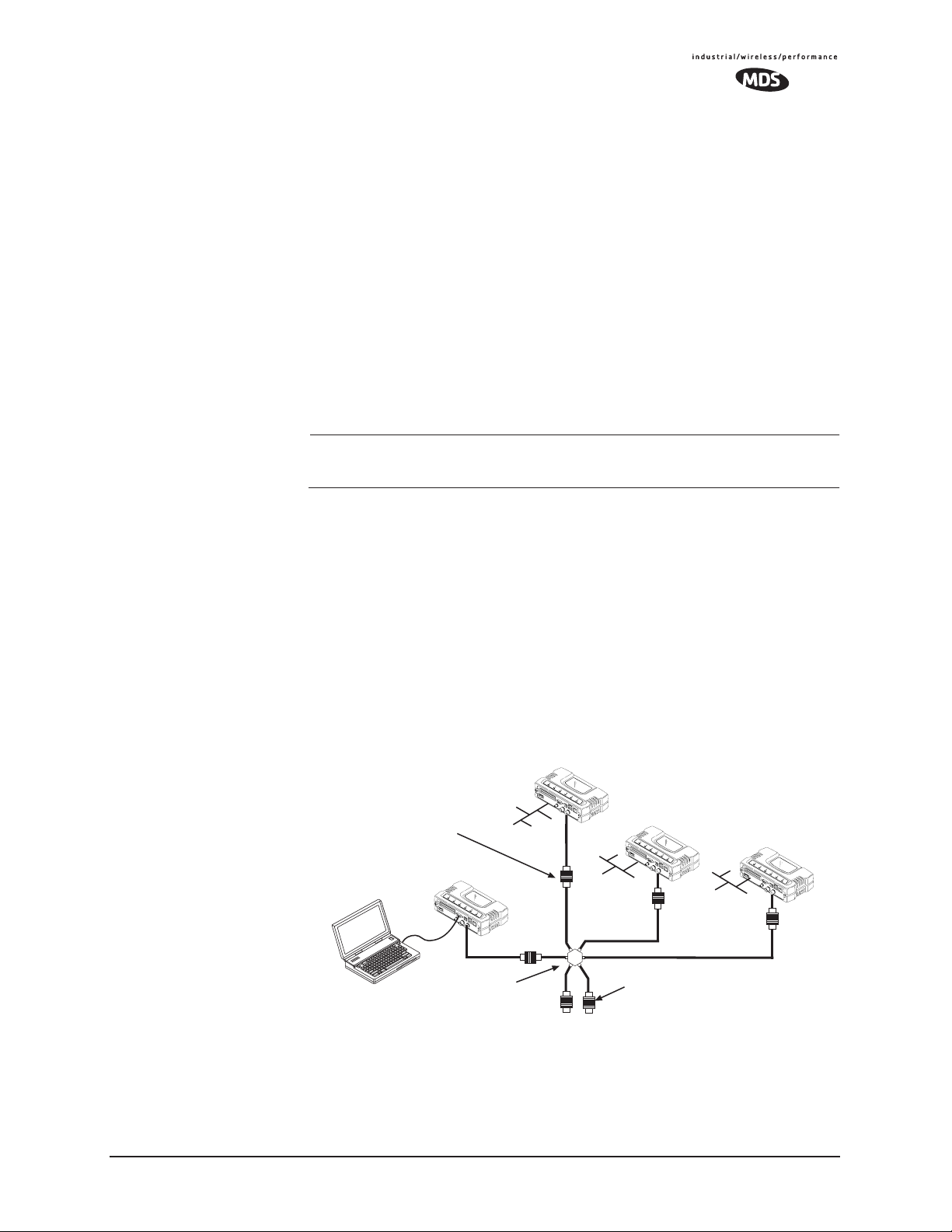
2.2 STEP 1—INSTALL THE ANTENNA
CABLING
Figure 2-1 is a drawing of the tabletop arrangement. Connect the
antenna ports of each transceiver as shown. This provides stable radio
communications between each unit and prevents interference to nearby
electronic equipment.
Invisible place holder
Remote
POWER ATTENUATORS
• Fixed or adjustable
• 1W Minimum Rating
Access Point
NON-RADIATING ATTENUATORS
COMPUTER
POWER DIVIDER
• Install on unused divider ports (if any)
• 1W Minimum Rating
Figure 2-1. Typical setup for tabletop-testing of radios
Remote
Remote
MDS 05-4446A01, Rev. A MDS Mercury User’s Guide 21
Page 30

NOTE: It is very important to use attenuation between all units in the
test setup. The amount of attenuation required will depend on
the number of units being tested and the desired signal strength
(RSSI) at each transceiver during the test. In no case should a
signal greater than –50 dBm be applied to any transceiver in
the test setup. An RF power output level of +20 dBm is recommended from the transceivers. (See “Radio Configuration
Menu” on Page 52.)
2.3 STEP 2—MEASURE & CONNECT
THE PRIMARY POWER
The primary power at the transceiver’s power connector must be within
10–30 Vdc and be capable of continuously providing 15 Watts (typical
power consumptions are: 760 mA @ 10.5 Vdc, 580 mA @ 13.8 Vdc,
and 267 mA @ 30 Vdc).
A Phoenix two-pole power connector with screw-terminals is provided
with each unit. Strip the wire leads to 6 mm (0.25"). Be sure to observe
proper polarity with the positive lead (+) on the left and negative (–) on
the right.
NOTE: It will take about 45 seconds for the transceiver to power up
and be ready for operation.
CAUTION
POSSIBLE
EQUIPMENT
DAMAGE
The transceiver must only be used with negative-ground power systems. Make sure the polarity of
the power source is correct.
2.4 STEP 3—CONNECT PC TO THE
TRANSCEIVER
Connect a PC’s Ethernet port to the LAN port using an Ethernet crossover cable. The
serial cable to connect to the
LAN LED should light. Alternatively, you can use a
COM1 port. (Figure 2-2 on Page 25)
2.5 STEP 4—REVIEW TRANSCEIVER
CONFIGURATION
2.5.1 Getting Started
Start by logging into the Access Point radio. This is done first because
the Remotes are dependent on the AP’s beacon signal to achieve an
“associated” state.
22 MDS Mercury User’s Guide MDS 05-4446A01, Rev. A
Page 31

NOTE: Transceivers are shipped from the factory set to the “Remote”
mode unless they are marked differently.
Once the Access Point is up and running, move the computer connection
to each of the Remote units, log-in at each unit, review their configuration, set their IP addresses and Network Name and wait for each to
achieve an associated state.
With all units associated, you will be ready to connect and test your data
services.
2.5.2 Procedure
The following is a summary of the configuration procedure that must be
done on each unit in the system. Key parameters are shown on the
Embedded Management System overview (Figure 3-1 on Page 32). A
lists of parameters can found in two tables: Table 4-5 on Page 129 and
Table 4-7 on Page 132. Detailed information on using the Management
System can be found in MS INTRODUCTION on Page 31.
NOTE: The Management System supports the use of “configuration
files” to aid in uniformly configuring multiple units. These are
detailed in Using Configuration Scripts on Page 107.
2.5.3 Basic Configuration Defaults
Table 2-1 provides a selection of key operating parameters, their range,
and default values. All of these are accessible through a terminal emulator connected to the
nected to the
LAN Port. (See Figure 5-1 on Page 139 for hookup.)
NOTE: Access to the transceiver’s Management System and changes
to some parameters, are controlled by password to maintain
security.
COM1 serial port or through a Web browser con-
MDS 05-4446A01, Rev. A MDS Mercury User’s Guide 23
Page 32

Table 2-1. Basic Configuration Defaults
Item Menu Location Default Values/Range
1
Device Mode
Network Name Main Menu>>
IP Address Main Menu>>
RF Output
Power
Unit Password Main Menu>>
1. Ethernet Bridge and Serial Gateway will not be displayed if a superior mode is authorized for this unit.
Main Menu>>
Network Configuration>>
Device Mode
Network Configuration>>
Network Name
Network Configuration>>
IP Address
Main Menu>>
Radio Configuration>>
RF Output Power
Device Information>>
User Password
Marked on unit’s
ID label
“Not
Programmed”
192.168.1.1 Contact your network
30 dBm (1.0
Watt)
admin
(lower case)
• Access Point
• Dual Remote
• Serial Gateway
• Ethernet Bridge
• 1–15 alphanumeric
characters
• Case-sensitive;
can be mixed case
administrator
20–30 dBm @ 50Ω
(0.1–1.0 Watts)
• 1–8 alphanumeric
characters
• Case-sensitive;
can be mixed case
A unique IP address and subnet are required to access the browser-based
Management System either through the
LAN port, or remotely
over-the-air.
2.6 STEP 5—CONNECT LAN AND/OR
SERIAL EQUIPMENT
Connect a local area network to the LAN port or a serial device to the
COM1 (DCE) port. The LAN port will support any Ethernet-compatible
equipment. This includes devices that use Internet Protocol (IP).
NOTE: If you configure COM1 for payload data service while you are
plugged into it, you will not be able to access the built-in
management system. Alternate methods for accessing the
management system are: use Telnet or the web browser
through the Ethernet port; use Telnet or the web browser over
the air (remote management from another radio).
Figure 2-2 shows the interface connectors on the front panel of the trans-
ceiver.
24 MDS Mercury User’s Guide MDS 05-4446A01, Rev. A
Page 33

LED INDICATOR
PANEL
PCMCIA SLOT*
Invisible place holder
COM1
SERIAL PORT
USB PORT 1*
PORTS 2&3*
LAN PORT
USB
* Not present on all units
TX/RX1
DC POWER INPUT
(10—30 VDC, 2.5A)
RX2 ANTENNA
GPS ANTENNA
CONNECTION
PORT
ANTENNA PORT
Figure 2-2. Transceiver Interface Connectors
• LED INDICATOR PANEL—Displays the basic operating status of
the transceiver. Section 2.7 contains detailed information.
•
PCMCIA SLOT— Connector slot that conforms to the standard
established by the Personal Computer Memory Card International Association. Can be used for a wireless card or other
PCMCIA device. Not present on all units.
•
COM1 SERIAL PORT— DB-9 connector used for management
of the transceiver via a connected PC. MS INTRODUCTION on
Page 31 provides complete connection details.
•
USB PORT 1—Universal Serial Bus connector conforming to
the Type-B standard. Not present on all units.
•
USB PORTS 2 & 3—Two Universal Serial Bus connectors con-
forming to the Type-A standard. Not present on all units.
•
LAN PORT—Connection point for Ethernet Local Area Net-
work.
•
PWR— DC power connection for the transceiver. Power source
must be 10–30 Vdc, negative ground, and capable of furnishing
at least 10 watts.
•
GPS ANTENNA PORT— Coaxial connector (SMA-type) for
connection of a Global Positioning System receiving antenna.
Compatible with powered GPS antennas.
•
RX2 ANTENNA PORT— Coaxial connector (TNC-type) for
attachment of a second receiving antenna used in space diversity arrangements.
•
TX/RX1 ANTENNA PORT— Coaxial connector (TNC-type) for
attachment of the main station antenna (transmit and receive).
MDS 05-4446A01, Rev. A MDS Mercury User’s Guide 25
Page 34

2.7 STEP 6—CHECK FOR NORMAL
OPERATION
Once the data equipment is connected, you are ready to check the transceiver for normal operation.
Observe the LEDs on the top cover for the proper indications. In a normally operating system, the following LED indications will be seen
within 45seconds of start-up:
•
PWR—Lit continuously
• LINK—On, or blinking intermittently to indicate traffic flow
• LAN—On, or blinking intermittently to indicate traffic flow
Figure 2-3 shows a close-up view of the transceiver’s LED Indicator
panel. Table 2-2 provides details on each LED function.
Invisible place holder
PWR
Figure 2-3. LED Indicator Panel
LANLINKLINKCOMGPS
26 MDS Mercury User’s Guide MDS 05-4446A01, Rev. A
Page 35

If the radio network seems to be operating properly based on observa-
Table 2-2. Transceiver LED Functions
LED Label Activity Indication
PWR ON Primary power (DC) present
Blinking Unit in “Alarmed” state
OFF Primary power (DC) absent
GPS ON Internal GPS receiver is
OFF Internal GPS receiver is not
COM
(MGT System)
LINK
(Access Point)
LINK
(Remote
Gateway)
LAN ON LAN detected
Blinking Data TX/RX
OFF No data activity
ON Default state
Blinking Data Tx/Rx
OFF Traffic exceeds the capacity of
ON Associated to AP
Blinking Data Tx/Rx
OFF Not associated with AP
Blinking Data TX/RX
OFF LAN not detected, or excessive
tion of the unit’s LEDs, you can use the
synchronized with the satellite
network.
synchronized with the satellite
network.
the radio network
traffic present
PING command to verify the link
integrity with the Access Point. This command can also be used to point
your browser to another Remote unit’s IP address in the same network.
MDS 05-4446A01, Rev. A MDS Mercury User’s Guide 27
Page 36

28 MDS Mercury User’s Guide MDS 05-4446A01, Rev. A
Page 37

EMBEDDED
3
3 Chapter Counter Reset Paragraph
Contents
3.1 MS INTRODUCTION............................................................... 31
3.2 ACCESSING THE MENU SYSTEM ........................................ 33
3.3 BASIC DEVICE INFORMATION.............................................. 40
3.4 CONFIGURING NETWORK PARAMETERS .......................... 44
MANAGEMENT SYSTEM
3.1.1 Differences in the User Interfaces ............................................ 31
3.2.1 Methods of Control ................................................................... 34
3.2.2 PC Connection & Log In Procedures ....................................... 34
3.2.3 Navigating the Menus .............................................................. 39
3.3.1 Starting Information Screen ..................................................... 40
3.3.2 Main Menu ............................................................................... 41
3.3.3 Configuring Basic Device Parameters ..................................... 42
3.4.1 Network Configuration Menu ................................................... 44
3.4.2 IP Address Configuration Menu ............................................... 46
3.4.3 Ethernet Port Configuration Menu ........................................... 47
3.4.4 DHCP Server Configuration ..................................................... 48
3.4.5 SNMP Agent Configuration ...................................................... 50
3.5 RADIO CONFIGURATION ...................................................... 52
3.5.1 Radio Configuration Menu ..................................................... 52
3.5.2 Mobile Data Configuration ....................................................... 59
3.6 CONFIGURING THE SERIAL INTERFACES.......................... 62
3.6.1 Overview .................................................................................. 62
3.6.2 Serial Data Port Configuration Menu ....................................... 65
3.6.3 Configuring for UDP Mode ....................................................... 66
3.6.4 Configuring for TCP Mode ....................................................... 69
3.6.5 Configuring for PPP Mode ....................................................... 72
3.6.6 IP-to-Serial Application Example .............................................. 73
3.6.7 Point-to-Point Serial-to-Serial Application Example ................. 74
3.6.8 Point-to-Multipoint Serial-to-Serial Application Example .......... 75
3.6.9 Mixed Modes ............................................................................ 77
3.7 CYBER SECURITY CONFIGURATION .................................. 79
MDS 05-4446A01, Rev. A MDS Mercury User’s Guide 29
Page 38

3.7.1 Device Security ........................................................................ 79
3.7.2 Wireless Security ..................................................................... 81
3.7.3 RADIUS Authentication ............................................................ 83
3.7.4 RADIUS Configuration ............................................................. 84
3.7.5 Certificate Management (Remote transceivers only) ............... 85
3.8 PERFORMANCE VERIFICATION ........................................... 86
3.8.1 Performance Information Menu ............................................... 86
3.8.2 Network Performance Notes .................................................... 97
3.9 MAINTENANCE......................................................................101
3.9.1 Reprogramming Menu ............................................................. 102
3.9.2 Configuration Scripts Menu ...................................................... 107
3.9.3 Authorization Keys Menu ......................................................... 116
3.9.4 Auto-Upgrade/Remote-Reboot Menu ...................................... 116
3.9.5 Radio Test Menu ...................................................................... 117
3.9.6 Ping Utility Menu ...................................................................... 119
3.9.7 Reset to Factory Defaults ......................................................... 119
30 MDS Mercury User’s Guide MDS 05-4446A01, Rev. A
Page 39

3.1 MS INTRODUCTION
The transceiver’s embedded management system is accessible through
various data interfaces. These include the
(Ethernet) port, and via SNMP. Essentially the same capabilities are
available through any of these paths.
For support of SNMP software, a set of MIB files is available for down-
load from the MDS Web site at www.microwavedata.com. A brief
summary of SNMP commands can be found at SNMP Agent Configura-
tion section on Page 50 of this manual.
The transceiver’s Management System and its functions are divided into
seven functional groups as listed below.
• Section 3.3, BASIC DEVICE INFORMATION (beginning on
Page 40)
• Section 3.4, CONFIGURING NETWORK PARAMETERS
(beginning on Page 44)
• Section 3.5, RADIO CONFIGURATION (beginning on Page
52)
• Section 3.6, CONFIGURING THE SERIAL INTERFACES
(beginning on Page 62)
• Section 3.7, CYBER SECURITY CONFIGURATION (begin-
ning on Page 78)
• Section 3.8, PERFORMANCE VERIFICATION (beginning on
Page 85)
• Section 3.9, MAINTENANCE (beginning on Page 100)
COM1 (serial) port, LAN
Each of these sections has a focus that is reflected in its heading. The
section you are now reading provides information on connecting to the
Management System, how to navigate through it, how it is structured,
and how to perform top-level configuration tasks. Figure 3-1 on the following page shows a top-level view of the Management System (MS).
3.1.1 Differences in the User Interfaces
There are slight differences in navigation among the user interfaces, but
for the most part, the content is the same. You will notice a few differences in capabilities as the communications tool is driven by limitations
of the access channel. Figure 3-2 and Figure 3-3 show examples of the
Starting Information Screen as seen through a console terminal and a
web-browser, respectively.
MDS 05-4446A01, Rev. A MDS Mercury User’s Guide 31
Page 40
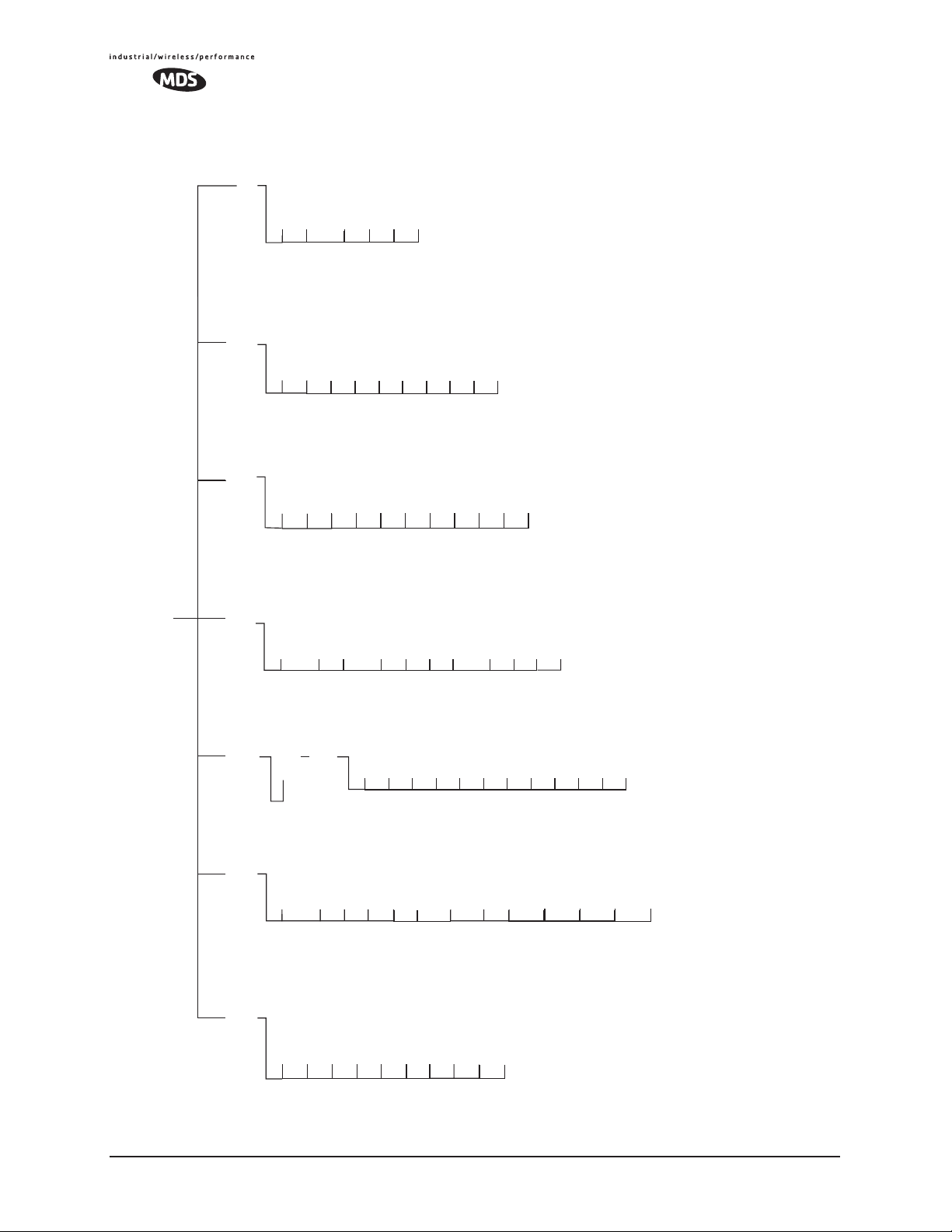
Maintenance/Tools
Reprogramming
Configuration
Scripts
Authorization Key
Radio Test
Ping Utility
Reset to Factory
Defaults
(AP)
(AP)
(AP)
Performance
Device
Security
MAIN MENU
Serial Gateway
Radio
Signal-to-Noise
RF Power Output
Information
Model Number
Information
Configuration
Configuration
Serial Number
Encryption
Authentication
Serial Config.
Wizard
COM1 & COM2
(RM)
RF Output
Power
Data Rate
Configuration
RSSI By Zone
Uptime
Firmware Version
(AP)
HTTP Access
Rotation
IP Protocol
Status
Event Log
Actual Data Rate
RSSI
Hardware Version
Auto Key
Serial Data Port
(AP)
Compression
(AP)
(AP)
Dwell Time
Beacon Period
Remote Listing
Packet Statistics
Console Baud Rate
SNMP Mode
Multicast IP Addr.
Hop Pattern
Endpoint Listing
Remote Perf.
Date
Login Status
Device Names
(AP)
Approved Remotes
List
Telnet Access
Multicast IP Port
(AP)
Seed
Encryption Phrase
Local IP Port
Time to Live
RTS Threshold
Fragmentation
Threshold
Listing
Time
Date Format
User Password
Force Key Rotation
HTTP Security Mode
Data Baud Rate
Packet sends
Configuration
SNR Threshold
(RMT)
RSSI Threshold
(RMT)
Flow Control
Serial Mode
Seamless
(AP)
RF Hopping
Format
Some models
Skip Zones (AP)
• Bolded items indicate a menu selection
(UDP Point-to-Point
example shown)
Inter-Frame Delay
Auto Data Rate Config.
• Spacebar used to make some menu selections
•AP = Access Point Only
• RM = Remote Only
(AP)
(AP)
NOTES
• Chart shows top-level view only. Details are given on the following pages.
• Not all items are user-configurable
• Some menu items depend on the Device Mode selected
Network
Device Mode
Network Name
SNTP Server
Max. Remotes
Database Timeout
IP Address Config.
Ethernet Addr. Config.
DHCP Server Config.
SNMP Agent Config.
Configuration
Mobility Mode
Figure 3-1. Embedded Management System—Top-level Flowchart
32 MDS Mercury User’s Guide MDS 05-4446A01, Rev. A
Page 41

Figure 3-2. View of MS with a text-based program—
(Terminal Emulator shown—Telnet has similar menu structure)
Invisible place holder
Figure 3-3. View of the MS with a Browser
(Selections at left provide links to the various menus)
3.2 ACCESSING THE MENU SYSTEM
The radio has no external controls. All configuration, diagnostics and
control is performed electronically using a connected PC. This section
explains how to connect a PC, log into the unit, and gain access to the
built-in menu screens.
MDS 05-4446A01, Rev. A MDS Mercury User’s Guide 33
Page 42

3.2.1 Methods of Control
The unit’s configuration menus may be accessed in one of several ways:
• Local Console—This is the primary method used for the exam-
ples in this manual. Connect a PC directly to the
using a serial communications cable and launch a terminal communications program such as HyperTerminal. This method provides text-based access to the unit’s menu screens. Console
control is a hardware-based technique, and is intended for local
use only.
• Telnet or SSH*—Connect a PC to the unit’s
directly or via a network, and launch a Telnet session. This
method provides text-based access to the unit’s menu screens in
a manner similar to a Local Console session. Telnet sessions
may be run locally or remotely through an IP connection.
• Web Browser*—Connect a PC to the unit’s
directly or via a network, and launch a web browser session
(i.e., Internet Explorer, Netscape, etc.) This method provides a
graphical representation of each screen, just as you would see
when viewing an Internet website. The appearance of menu
screens differs slightly from other methods of control, but the
content and organization of screen items is similar. Web
browser sessions may be run locally or remotely via the Internet.
COM 1 port
LAN port, either
LAN port, either
* Telnet, SSH and Web Browser sessions require the use of a straight-through or
crossover Ethernet cable, depending on the whether the PC-to-radio connection is
made directly, or through a network. For direct connection, a crossover cable is
required; For connection via a network, a straight-through type is needed.
Cable type can be identified as follows: Hold the two cable ends side-by-side and in
the same plug orientation (i.e., both locking tabs up or down). Now look at the
individual wire colors on each plug. If the wires on both plugs are ordered in the
same sequence from left to right, the cable is a straight-through type. If they are not
in the same order, it may be a crossover cable, or it may be wired for some other
application. Refer to DATA INTERFACE CONNECTORS on Page 153 for detailed
pinout information.
3.2.2 PC Connection & Log In Procedures
The following steps describe how to access the radio’s menu system.
These steps require a PC to be connected to the unit’s
as shown in Figure 3-4.
COM 1 or LAN port
34 MDS Mercury User’s Guide MDS 05-4446A01, Rev. A
Page 43

PC Running Terminal Session
(19,2000 bps, 8N1)
Figure 3-4. PC Configuration Setup
Invisible place holder
To COM1 or LAN Port
(See Text)
Starting a Local
Console Session
(Recommended for
first-time log-in)
1. Connect a serial communications cable between the PC and the
unit’s
COM 1 port. If necessary, a cable may be constructed for this
purpose as shown in Figure 3-5.
Invisible place holder
DCE
DB-9 MALE
(TO MDS PRODUCT)
RXD
TXD
GND
2
3
5
Figure 3-5. Serial Communications Cable (DB-9M to DB-9F)
(Maximum Recommended Cable Length 50 Feet/15 meters)
DTE
DB-9 FEMALE
(TO COMPUTER)
RXD
2
TXD
3
GND
5
2. Launch a terminal emulation program such as HyperTerminal and
configure the program with the following settings:
• 19,200 bps data rate
•8 data bits, no parity
• One stop bit, and no flow-control
• Use ANSI or VT100 emulation.
TIP: The HyperTerminal communications program can be accessed on
most PCs by selecting this menu sequence:
ries>>Communications>>HyperTerminal
.
Start>>Programs>>Accesso-
NOTE: Early versions of PuTTY may not operate when using SSH to
connect to the transceiver. The latest version (beta 0.58 at the
time of publication) does not work with the transceiver’s
internal server. However, the latest development snapshot
does work properly. Both the latest released and the latest
development snapshot can be downloaded from:
www.chiark.greenend.org.uk/~sgtatham/putty/.
MDS 05-4446A01, Rev. A MDS Mercury User’s Guide 35
Page 44
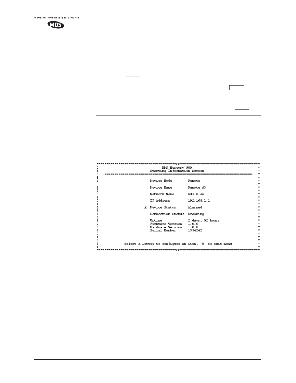
NOTE: If the unit is powered-up or rebooted while connected to a
terminal, you will see a series of pages of text information
relating to the booting of the unit’s microcomputer. Wait for
the log-in screen before proceeding.
3. Press the key to receive the login: prompt.
4. Enter the username (default username is
ENTER
admin). Press .
ENTER
5. Enter your password (def ault password is admin). (F or security, your
password keystrokes do not appear on the screen.) Press .
ENTER
NOTE: Passwords are case sensitive. Do not use punctuation mark
characters. You may use up to eight alpha-numeric characters.
The unit responds with the Starting Information Screen (Figure 3-6).
From here, you can review basic information about the unit or press
G
to proceed to the Main Menu.
Invisible place holder
Figure 3-6. Starting Information Screen—Local Console Session
(Telnet has similar menu structure)
Starting a Telnet
Session
NOTE: This method requires that you know the IP address of the unit
beforehand. If you do not know the address, use the Local
Console method (above) and access the Starting Information
Screen. The address is displayed on this screen.
1. Connect a PC to the unit’s
LAN port, either directly or via a network.
If connecting directly, use an Ethernet crossover cable; if
connecting via a network, use a straight-through cable. The
LAN
LED lights to indicate an active connection.
36 MDS Mercury User’s Guide MDS 05-4446A01, Rev. A
Page 45

NOTE: When using Ethernet to access the unit, it may be necessary to
ENTER
change your computer’s IP access to be compatible with the
radio IP address. You can identify or verify the unit’s IP
address by using a Local Console session to communicate with
the radio through its COM 1 Port and viewing the Starting
Information Screen.
2. Start the Telnet program on your computer targeting the IP address
of the unit to which you are connected. and press .
ENTER
TIP: A Telnet session can be started on most PCs by selecting:
Start>>Programs>>Accessories>>Command Prompt. At the command
prompt window, type the word
address (e.g., telnet 10.1.1.168). Press to receive the Telnet
telnet, followed by the unit’s IP
ENTER
log in screen.
NOTE: Never connect multiple units to a network with the same IP
address. Address conflicts will result in improper operation.
Starting a Web
Browser Session
3. Enter your username (default username is admin). Press .
Next, the
password is
Password: prompt appears. Enter your password (default
admin). (For security, your password keystrokes will not
ENTER
appear on the screen.) Press .
The unit responds with a Starting Information Screen (see
Figure 3-6). From here, you can review basic information about the
unit or press
G to proceed to the Main Menu.
NOTE: Passwords are case sensitive. Do not use punctuation mark
characters. You may use up to eight alpha-numeric characters.
NOTE: Web access requires that you know the IP address of the unit
you are connecting to. If you do not know the address, start a
Local Console session (see Starting a Local Console Session
(Recommended for first-time log-in) on Page 35) and access
the Starting Information Screen. The IP address is displayed
on this screen.
1. Connect a PC to the unit’s
LAN port, either directly or via a network.
If connecting directly, use an Ethernet crossover cable; if
connecting via a network, use a straight-through cable. The
LAN
LED lights to indicate an active connection.
2. Launch a Web-browser session on your computer (i.e., Internet
Explorer, Netscape Navigator, etc.).
MDS 05-4446A01, Rev. A MDS Mercury User’s Guide 37
Page 46

3. Type in the unit’s IP address and press .
ENTER
4. A log-in screen is displayed (Figure 3-7) where you enter a user
name and password to access the unit’s menu system. Note that the
default entries are made in lower case. (Default User Name:
Default Password:
admin)
admin;
Invisible place holder
admin
Figure 3-7. Log-in Screen when using a Web Browser
NOTE: Passwords are case sensitive. Do not use punctuation mark
characters. You may use up to eight alpha-numeric characters.
5. Click
OK. The unit responds with a startup menu screen similar to
that shown in Figure 3-8. From here, you can review basic information about the unit or click on one of the menu items at the left side
of the screen.
Invisible place holder
Figure 3-8. Starting Information Screen—Web Browser Example
38 MDS Mercury User’s Guide MDS 05-4446A01, Rev. A
Page 47

3.2.3 Navigating the Menus
SPACEBAR
ESCAPE
Via Terminal Telnet or SSH Sessions
Recommended for first-time log-in
Local Console Telnet and SSH sessions use multi-layered text menu
systems that are nearly identical. To move further down a menu tree,
you type the letter assigned to an item of interest. This takes you to an
associated screen where settings may be viewed, or changed. In most
cases, pressing the
menu tree.
In general, the top portion of menu screens show read-only information
(with no user selection letter). The bottom portion of the screen contains
parameters that can be selected for further information, alteration of
values, or to navigate to other submenus.
When you arrive at a screen with user-controllable parameter fields, you
select the menu item by pressing an associated letter on the keyboard. If
there is a user definable value, the field will clear to the right of the menu
item and you can type in the value you wish to use. Follow this action
by pressing the key to save the changes. If you make a mistake
or change your mind before pressing the key, simply press
ESCAPE
to restore the previous value.
ESCAPE
ENTER
key moves the screen back one level in the
ENTER
Logging Out Via
Terminal Emulator
or Telnet
In some cases, when you type a letter to select a parameter, you will see
a prompt at the bottom of the screen that says
Choose an Option. In these
screens, press the keyboard’s to step through the available
selections. When the desired option appears, press the key to
ENTER
choose that selection. In some cases, several parameters may be changed
and then saved by a single keystroke. The key can be used to
cancel the action and restore the previous values.
From the Main Menu screen, press Q to quit and terminate the session.
Navigating via Web Browser
Navigating with a Web browser is straightforward with a framed
“homepage.” The primary navigation menu is permanently located on
the left-hand side of this page. Simply click on a desired menu item to
bring it to the forefront.
NOTE: To maintain security, it is best to log-out of the menu system
entirely when you are done working with it. If you do not log
out, the session automatically ends after 10 minutes of inactivity.
Logging Out Via
Web Browser
Click on Logout in the left-hand frame of the browser window. The
right-hand frame will change to a logout page. Follow the remaining
instructions on this screen.
MDS 05-4446A01, Rev. A MDS Mercury User’s Guide 39
Page 48

NOTE: In the menu descriptions that follow, parameter options/range,
and any default values are displayed at the end of the text
between square brackets. Note that the default setting is
always shown after a semicolon: [available settings or range;
default setting]
3.3 BASIC DEVICE INFORMATION
This section contains detailed menu screens and settings that you can
use to specify the behavior of the unit.
3.3.1 Starting Information Screen
Once you have logged into the Management System, you will be presented with a screen that provides an overview of the transceiver and its
current operating condition. It provides an array of vital information and
operating conditions.
Figure 3-9. Starting Information Screen
• Device Mode—Current operating mode of the unit as it relates to
the radio network.
•
Device Name—This is a user-defined parameter that will appear
in the heading of all pages.
(To change it, see Network Configuration Menu on Page 44.)
•
Network Name—The name of the radio network in which the unit
is associated.
•
IP Address—Unit’s IP address [192.168.1.1]
• Device Status—Condition of the unit’s association with an
Access Point.
At the Access Point:
• Alarmed—A alarm event has been logged and not cleared.
• Operational—Unit operating normally.
At a Remote:
40 MDS Mercury User’s Guide MDS 05-4446A01, Rev. A
Page 49

• Scanning—The unit is looking for an Access Point beacon
signal.
• Exp(ecting) Sync(hronization)—The unit has found a valid
beacon signal for its network.
• Hop Sync—The unit has changed its frequency hopping pat-
tern to match that of the Access Point.
• Associated —This unit has successfully synchronized and
associated with an Access Point.
• Alarmed—The unit is has detected one or more alarms that
have not been cleared.
NOTE: If an alarm is present when this screen is displayed, an “A)”
appears to the left of the Device Status field. Pressing the “A”
key on your keyboard takes you directly to the “Current
Alarms” screen.
Uptime—Elapsed time since the transceiver was powered-up.
•
• Firmware Version—Version of firmware that is currently active in
the unit.
•
Hardware V ersion— Hardware version of the transceiver’ s printed
circuit board.
•
Serial Number—Make a record of this number. It must be pro-
vided to purchase Authorization Keys to upgrade unit capabilities. (See “Authorization Keys Menu” on Page 114.)
3.3.2 Main Menu
The next screen, the Main Menu, is the entryway to all user-controllable
features. The transceiver’s
other screens as a reminder of the unit that is currently being controlled
Device Name appears at the top of this and all
Figure 3-10. Main Menu
MDS 05-4446A01, Rev. A MDS Mercury User’s Guide 41
Page 50

• Starting Information Screen—Select this item to return to the
start-up screen. (See “Starting Information Screen” on
Page 40)
•
Network Configuration—Tools to configure the data network layer
of the transceiver. (See “Network Configuration Menu” on
Page 44)
•
Radio Configuration—Tools to configure the wireless (radio)
layer of the transceiver. (See “Radio Configuration Menu” on
Page 52)
•
Serial Gateway Configuration—Tools to configure the two serial
ports. (See “Serial Data P ort Configuration Menu” on Page 65)
•
Security Configuration—Tools to configure the security services
available with the transceiver’s environment. (See “MDS
CYBER SECURITY SUITE” on Page 14)
•
Device Information—Top level user-specific and definable param-
eters, such as unit password. (See “Device Information” on
Page 42)
•
Performance Information—Tools to measure the radio and data
layer’s performance of the radio network. (See “Performance
Information Menu” on Page 85)
•
Maintenance/Tools—Tools to use configuration files, change
firmware and use Authorization Keys to change major unit
capabilities. (See “Authorization Keys Menu” on Page 114)
3.3.3 Configuring Basic Device Parameters
Device Information
Below is the menu/screen that displays basic administrative data on the
unit to which you are connected. It also provides access to some userspecific parameters such as device names.
Figure 3-11. Device Information Menu
• Model Number (Display only)
• Serial Number (Display only)
42 MDS Mercury User’s Guide MDS 05-4446A01, Rev. A
Page 51

• Hardware V ersion (Display only)
• Firmware Version (Display only)—Current firmware installed and
being used by the transceiver.
•
Uptime (Display only)—Elapsed time since powering up.
• Console Baud Rate—Used to set/display data communications
rate (in bits-per-second) between a connected console terminal
and the radio. [
19200]
• Device Names Menu—Fields used at user’s discretion for general
administrative purposes. The Device Name field is used by the
transceiver as the “Realm” name for network security and in the
MS screen headings. (See Figure 3-12 on Page 43)
•
Date—Current date being used for the transceiver logs. User-set-
able. (Value lost with power failure if SNTP (Simple Network
Time Protocol) server not accessible.)
•
Time—Current time of day. User-setable.
Setting: HH:MM:SS
(Value lost with power failure if SNTP server not accessible.)
•
Date Format—Select presentation format:
• Generic = dd Mmm yyyy
• European = dd-mm-yyyy
• US = mm-dd-yyyy
Device Names Menu
Figure 3-12. Device Names Menu
• Device Name—Device Name, used by the transceiver as the
“Realm” name for network login (web browser only) and
menu headings.
•
Owner—User defined; appears on this screen only.
• Contact—User defined; appears on this screen only.
• Description—User defined; appears on this screen only.
• Location—User defined; appears on this screen only.
MDS 05-4446A01, Rev. A MDS Mercury User’s Guide 43
Page 52

3.4 CONFIGURING NETWORK
PARAMETERS
3.4.1 Network Configuration Menu
The Network Configuration Menu is the home of three parameters that
should be reviewed and changed as necessary before placing a transceiver in service—Device Mode, IP Address and Network Name.
Screens for both the Access Point and Remote units are shown below.
Figure 3-13. Network Configuration Menu
From Access Point
Figure 3-14. Network Configuration Menu
From Remote Unit
44 MDS Mercury User’s Guide MDS 05-4446A01, Rev. A
Page 53

• Device Mode (User Review Recommended)—Either Access Point or
a variation of a Remote. [
Remote]
• Network Name (User Review Required)—Name of the radio network
of which this unit will be a part. Essential for association of
Remotes to the Access Point in the network. [
Not Programmed]
TIP: For enhanced security, consider using misspelled words, a combi-
nation of letters and numbers, and a combination of upper and
lower case letters. Also, the Network Name should be at least nine
characters long. This helps protect against sophisticated hackers
who may use a database of common words (for example, dictionary attacks) to determine the Network Name.
•
SNTP Server—Address of SNTP server (RFC 2030) from which
the transceiver will automatically get the time-of-day startup
time. Without an SNTP server, the date and time must be manually set. An AP will try to get the time and date from the SNTP
server only if an IP address is configured. It will continue to
retry every minute until it succeeds.
A remote will get the time and date from the SNTP server, if an
IP address is configured. Otherwise it gets it from the AP at
authentication time. The transceivers use UTC (Universal Time
Constant) with a configurable time offset. [
0.0.0.0]
• IP Address Configuration Presents a menu for configuring the
local static IP address of the transceiver. Detailed explanations
are provided in the section titled IP Address Configuration
Menu on Page 46
•
Ethernet Port Configuration—Presents a menu for defining the sta-
tus of the Ethernet port (enabled or disabled), the Ethernet rate
limit, link hardware watch (enabled/disabled), and the Ethernet
link poll address. Detailed explanations of this menu are contained in Ethernet Port Configuration Menu on Page 47
•
DHCP Server Config(uration)—Menu for configuration of DHCP
services by the Access Point unit. DHCP provides “on-the-fly”
IP address assignments to other LAN devices, including MDS
Mercury 900 units. [
Disabled]
• SNMP Config Menu—SNMP configuration parameters.
• Mobility Mode—Used to configure whether the transceiver is
enabled or disabled for mobility operation. Note that this selec-
tion may appear on both Access Point and Remote menus, but it
only takes effect when set on Remotes. Additional settings and
information for mobility operation are contained in Mobile
Data Configuration on Page 59. [
enabled, disabled; disabled].
• Maximum Remotes (AP Only)—Number of Remotes permitted to
be associated with (served by) this Access Point. [
50]
MDS 05-4446A01, Rev. A MDS Mercury User’s Guide 45
Page 54

• Database Timeout (AP Only)—This sets the database “age time”
(Remote Listing Menu (Access Points Only) on Page 93) to
determine when a remote is declared as unavailable. The timer
may be set from 0 to 255 minutes and resets each time a message
is received from a remote. [
0–255 minutes; 5 minutes]
• Database Logging (AP Only)—Determines which types of devices
will be reported as “added” or “deleted” from the AP’s database
(See Section 3.8.1, Performance Information Menu (beginning
on Page 85). In the case of deletions, this information is trig-
gered by a timer expiration as described in the item above.
Available selections are:
Disabled.
Remote, All (endpoints and remotes), or
• Ethernet Address (Display Only)—Hardware address of this unit’s
Ethernet interface.
•
Wireless Address (Display Only)—Hardware address of the unit’s
wireless interface.
3.4.2 IP Address Configuration Menu
The radios use a local IP address to support remote management and
serial device services. The IP address of a radio can be set as a static IP
address or as a dynamic IP address. When static IP addressing is used,
the user must manually configure the IP address and other parameters.
When dynamic addressing is used, the radio uses a DHCP Client process
to obtain an IP address from a DHCP Server, along with other parameters such as a net mask and a default gateway.
Figure 3-15. IP Address Configuration Menu
46 MDS Mercury User’s Guide MDS 05-4446A01, Rev. A
Page 55

CAUTION: Changes to any of the following parameters while
communicating over the network (LAN or over-the-air) may cause
a loss of communication with the unit being configured. Communication will need to be re-established using the new IP address.
• IP Address Mode—Defines the source of the IP address of this
device. [
Static, Dynamic; Static]
• Dynamic Mode—Enabling this option forces the transceiver (AP
or Remote) to obtain an IP address from any DHCP server available on the LAN. Dynamic Mode is also known as DHCP Client
mode. [
Disabled]
• Static IP Address (User Review Recommended)—Essential for connectivity to the transceiver’s MS via the
LAN port and to send
Ethernet data over the network. Enter any valid IP address that
will be unique within the network. [
This field is unnecessary if DHCP is enabled. [
Static IP Netmask—The IPv4 local subnet mask. This field is
unnecessary if DHCP is enabled. [
192.168.1.1]
255.255.0.0]
255.255.0.0]
• Static IP Gateway—The IPv4 address of the network gateway
device, typically a router. This field is unnecessary if DHCP is
enabled. [
0.0.0.0]
The lower three lines of the screen show the actual addressing
at the transceiver whether it was obtained from static configuration or from a DHCP server.
NOTE: Any change made to the above parameters results in the
Commit Changes option appearing on screen. This allows all IP
settings to be changed at the same time.
3.4.3 Ethernet Port Configuration Menu
The transceiver allows for special control of the Ethernet interface, to
allow traffic awareness and availability of the backhaul network for
redundancy purposes.
NOTE: The transceiver’s network port supports 10BaseT and
100BaseT connections. Confirm that your hub/switch is
capable of auto-switching data rates.
To prevent excessive Ethernet traffic from degrading performance, place the transceiver in a segment, or behind routers.
MDS 05-4446A01, Rev. A MDS Mercury User’s Guide 47
Page 56

Figure 3-16. Ethernet Port Configuration Menu
• Ethernet Port Status—Allows enabling/disabling Ethernet traffic
for security purposes. Setting it to
Follows Link Status enables the
port if there is a connection established with the AP, but disables
it otherwise. [AP:
[Remote:
Always On, Follow Radio Link, Disabled; Always On]
Enabled, Disabled; Enabled]
• Ethernet Rate Limit—The transceiver will send alarms (SNMP
traps) when the rate reaches 50%, 75%, and 100% to help identify potential problems with traffic.
•
Ethernet Link (H/W) Watc h (AP Only)—Detects the lack of an Ether-
net connection to the LAN port at the electrical level (link integrity). The current AP will broadcast a beacon signal indicating
its “NOT AVAILABLE” status so Remotes that hear it do not
try to associate to it. Once the Ethernet connection is restored,
this beacon signal changes to “AVAILABLE” and Remotes are
allowed to join in. [
Disabled]
• Ethernet Link Poll Address (AP Only)—When an IP address is pro-
vided, the Access Point pings the remote IP device every 2 minutes to test the integrity of the backhaul link. If this link is not
available, the AP will advertise its “NOT AVAILABLE” status
in the beacon signal so Remotes do not try to associate to it.
Once the IP address is reachable, this beacon signal changes to
“AVAILABLE” and Remotes are allowed to join in. 0.0.0.0 disables this function. Any other valid IP address enables it.
[
0.0.0.0]
3.4.4 DHCP Server Configuration
A transceiver can provide automatic IP address assignments to other IP
devices in the network by providing DHCP (Dynamic Host Configuration Protocol) services. This service eliminates setting individual device
IP address on Remotes in the network, but it still requires thoughtful
48 MDS Mercury User’s Guide MDS 05-4446A01, Rev. A
Page 57

planning of the IP address range. One drawback to network-wide automatic IP address assignments is that SNMP services may become inaccessible as they are dependent on fixed IP addresses.
The network can be comprised of radios with the DHCP-provided IP
address enabled or with DHCP services disabled. In this way, you can
accommodate locations for which a fixed IP address if desired.
Figure 3-17. DHCP Server Configuration Menu
NOTE: There should be only one DHCP server acti ve in a network. If
more than one DHCP server exists, network devices may
randomly get their IP address from different servers every time
they request one.
NOTE: Combining DHCP and RADIUS device authentication may
result in a non-working radio module if the DHCP server is
located at a remote radio. The DHCP server should be placed
at the AP location, if possible.
•
Server Status—Enable/Disable responding to DHCP requests to
assign an IP address. [
Disabled/Enabled; Disabled]
• DHCP Netmask—IP netmask to be assigned along with the IP
address in response to a DHCP request. [
0.0.0.0]
• Starting Address—Lowest IP address of the range of addresses to
be provided by this device. [
0.0.0.0]
• Ending Address—Highest IP address in the range of addresses to
be provided by this device. A maximum of 256 addresses is
allowed in this range. [
0.0.0.0]
• DNS Address—Domain Name Server address to be provided by
this service.
•
WINS Address—Windows Internet Naming Service server
address to be provided by this service.
MDS 05-4446A01, Rev. A MDS Mercury User’s Guide 49
Page 58

• Restart DHCP Server—Selecting this option forces the transceiver
to start servicing DHCP requests using the Starting Address.
Payload data will not be interrupted but may experience some
delays as new addresses are distributed.
3.4.5 SNMP Agent Configuration
The transceiver contains over 100 custom SNMP-manageable objects as
well as the IETF standard RFC1213 for protocol statistics, also known
as MIB II. Off-the-shelf SNMP managers such as Castle Rock Computing SNMPc™ and Hewlett Packard HP OpenView™ may also be
used to access the transceiver’s SNMP Agent’s MIB. The transceiver’s
SNMP agent supports SNMPv3.
The objects are broken up into nine MIB files for use with your SNMP
manager. There are textual conventions, common files and specific files.
This allows the flexibility to change areas of the MIB and not affect
other existing installations or customers.
•
msdreg.mib—MDS sub-tree registrations
• mds_comm.mib—MDS Common MIB definitions for objects
and events which are common to the entire product family
•
mercury_reg.mib—MDS sub-tree registrations
• mercurytrv1.mib—SNMPv1 enterprise-specific traps
• mercurytrv2.mib—SNMPv2 enterprise-specific traps
• mercury_comm.mib— MIB definitions for objects and events
which are common to the entire Mercury Series
•
mercury_ap.mib—MIB definitions for objects and events for an
Access Point transceiver
•
mercury_sta.mib—Definitions for objects and events for a
Remote radio
•
mercury_sec.mib—For security management of the radio system.
SNMPv3 allows read/write operation. SNMPv1/2 allows only
for read-only access.
NOTE: SNMP management requires that the proper IP address,
network and gateway addresses are configured in each transceiver of the associated network.
In addition, some management systems may require the MIB
files to be compiled in the order shown above.
50 MDS Mercury User’s Guide MDS 05-4446A01, Rev. A
Page 59

Invisible place holder
Figure 3-18. SNMP Server Configuration Menu
From Access Point
This menu provides configuration and control of vital SNMP functions.
•
Read Community String—SNMP community name with
SNMPv1/SNMPv2c read access. This string can be up to 30
alpha-numeric characters.
•
Write Community String—SNMP community name with
SNMPv1/SNMPv2c write access. This string can be up to 30
alpha-numeric characters.
•
Trap Community String—SNMP community name with
SNMPv1/SNMPv2c trap access. This string can be up to 30
alpha-numeric characters.
•
V3 Authentication Password—Authentication password stored in
flash memory. This is used when the Agent is managing passwords locally (or initially for all cases on reboot). This is the
SNMPv3 password used for Authentication (currently, only
MD5 is supported). This string can be up to 30 alpha-numeric
characters.
•
V3 Privacy Pass wor d Privacy password stored in flash memory.
Used when the SNMP Agent is managing passwords locally (or
initially for all cases on reboot). This is the SNMPv3 password
used for privacy (DES encryption). This string can be between
8 and 30 alpha-numeric characters.
•
SNMP Mode—This specifies the mode of operation of the radio’s
SNMP Agent. The choices are: disabled, v1_only, v2_only,
v3_only. v1-v2, and v1-v2-v3. If the mode is disabled, the
Agent does not respond to any SNMP traffic. If the mode is
v1_only, v2_only, or v3_only, the Agent responds only to that
version of SNMP traffic. If the mode is v1-v2, or v1-v2-v3, the
Agent responds to the specified version of SNMP traffic.
[
v1-v2-v3]
MDS 05-4446A01, Rev. A MDS Mercury User’s Guide 51
Page 60

• Trap Version—This specifies what v ersion of SNMP will be used
to encode the outgoing traps. The choices are v1_traps,
v2_traps, and v3_traps. When v3_traps are selected, v2-style
traps are sent, but with a v3 header. [
v1 T raps, v2 T raps, v3 Traps]
• Auth T raps Status—Indicates whether or not traps will be generated for login events to the transceiver. [
abled
]
Disabled/Enabled; Dis-
• SNMP V3 P asswords—Determines whether v3 passwords are
managed locally or via an SNMP Manager. The different behaviors of the Agent depending on the mode selected, are described
in
SNMP Mode above.
• Trap Manager #1–#4— Table of up to 4 locations on the network
that traps are sent to. [
Any standard IP address]
NOTE: The number in the upper right-hand corner of the screen is the
SNMP Agent’s SNMPv3 Engine ID. Some SNMP Managers
may need to know this ID in order interface with the transceiver’s SNMP Agent. The ID only appears on the screen
when SNMP Mode is either v1-v2-v3 or v3_only.
3.5 RADIO CONFIGURATION
There are two primary data layers in the transceiver network—radio and
data. Since the data layer is dependent on the radio layer working properly, configuration of the radio items should be reviewed and set before
proceeding. This section explains the Radio Configuration Menu,
(Figure 3-19 for AP, Figure 3-20 for Remote). The Configuration Menu
is followed a secondary menu, the Skip Zone Options.
3.5.1 Radio Configuration Menu
Figure 3-19. Radio Configuration Menu From Access Point
52 MDS Mercury User’s Guide MDS 05-4446A01, Rev. A
Page 61

Figure 3-20. Radio Configuration Menu
From Remote Unit
• RF Output Power (User Review Recommended)—Sets/displays RF
power output level. Displayed in dBm. Setting should reflect
local regulatory limitations and losses in antenna transmission
line. (See “How Much Output Power Can be Used?” on
Page 144 for information on how to calculate this value.)
[
20–30; 20]
• Data Rate (Remote Only. AP fixed is at 512/1 Mbps.)—Shows the
over-the-air data rate setting for the Remote radio. Remotes can
operate at one of two data rates when communicating with an
AP; 512 kbps or 1 Mbps. Higher speeds are possible with strong
RF signal levels, typically stronger than –77 dBm RSSI including a 15 dB fade margin.
When the data rate is set to
AUTO, the remote radio is able to
change speeds based on the signal quality criteria set in the Auto
Data Rate submenu described later in this section (see Page 56).
[
256, 512, AUTO; AUTO]
•
Compression (AP Only)—Enabling this option uses LZO com-
pression algorithm for over-the-air data. Varying levels of data
reduction are achieved depending on the nature of the information. Text files are typically the most compressible, whereas
binary files are the least compressible. On average, a 30%
increase in throughput can be achieved with compression
enabled.
•
Dwell Time—Duration (in milliseconds) of one hop on a particu-
lar frequency in the hopping pattern. (This field is only changeable on an Access Point. Remotes get their value from AP upon
association.) [
MDS 05-4446A01, Rev. A MDS Mercury User’s Guide 53
8.2, 16.4, 32.8, 65.5, 131.1; 32.8]
Page 62

TIP: If a packet is being transmitted and the dwell time
expires, the packet will be completed before hopping to the next
frequency.
Beacon Period—Amount of time between Beacon transmissions
•
(in msec).
Available Intervals:
ms),
Slow (508 ms), Moderate (208 ms). These values provide rel-
Normal (104 ms), Fast (52 ms), Faster (26
atively quick association times where Fast is very fast (≈ 5 sec)
and the other end, the largest recommended value, the 508 ms
period is slow (≈ 60 sec). [
mal
]
Normal, Fast, F aster , Slow, Moderate; Nor -
TIP: Increasing the Beacon Period will provide a small
improvement in network data throughput. Shortening it
decreases the time needed for Remotes to associate with
the AP. A short beacon period is usually only a benefit
when there are mobile Remotes in the network.
•
Hop Pattern Seed—A user-selectable value to be added to the hop
pattern formula. This is done in the unlikely event that identical
hop patterns are used with two collocated or nearby networks.
Changing the seed value will minimize the potential for RF-signal collisions in these situations. (This field is only changeable
on an Access Point. Remotes read the AP’s value upon association.) [
0 to 255; 1]
• Fragment Threshold—Before transmitting over the air , if a packet
exceeds this number of bytes, the transceiv er sends the packet in
multiple fragments that are reassembled before being delivered
over the Ethernet interface at the receiving end. Only e ven numbers are acceptable entries for this parameter. Over-the-air data
fragmentation is not supported on AP units. ( See “Network Per-
formance Notes” on Page 96 for additional information.)
[
256–1600 bytes; 1600]
TIP: In an interference-free environment this value should be
large to maximize throughput. If interference exists then
the value should be set to smaller values. The smaller the
packet the less chance of it being interfered with at the cost
of slightly reduced throughput.
•
RTS Threshold—Number of bytes for the over-the-air RTS/CTS
handshake boundary. (See “Network Performance Notes” on
Page 96.) [
0 to 1600 bytes; 500]
NOTE: While the transceiver accepts RTS Threshold values below
100, the lowest value that works is 100.
54 MDS Mercury User’s Guide MDS 05-4446A01, Rev. A
Page 63

TIP: Lower the RTS Threshold as the number of Remotes or
overall over-the-air traffic increases. Using RTS/CTS is a
trade-off, giving up some throughput in order to prevent
collisions in a busy over-the-air network.
The
RTS Threshold should be enabled and set with a value
smaller than the
Fragmentation Threshold described above.
RTS forces the Remotes to request permission from the
AP before sending a packet. The AP sends a CTS control
packet to grant permission to one Remote. All other
Remotes wait for the specified amount of time before
transmitting.
•
RSSI Threshold (for alarm)—Level (dBm) below which the
received signal strength is deemed to have degraded, and a critical event (alarm) is generated and logged. Under these conditions, the
manager if SNMP is enabled and set properly. [
PWR lamp flashes, and a trap is sent to the trap
0 to -120; -90]
• SNR Threshold (for alarm)—Value (dB) below which the sig-
nal-to-noise ratio is deemed to have degraded and a critical
event is generated and logged. Under these conditions, the
PWR
lamp flashes, and a trap is sent to the trap manager if SNMP is
enabled and set properly. [
0 to 40; Not Programmed]
• RF Hopping Format—Operation must be compliant with country-specific restrictions for the frequency band used. This option
must be specified when the order is placed and cannot be modified in the field by the user. The available formats are:
•
ISM: 902–928 MHz band
• GSM: 915–928 MHz band
• SPLIT: 902-907.5 and 915-928 MHz bands
• CHANNELS: 902–928 MHz, selectable, from 1 to 80 channels.
NOTE: When using CHANNELS mode, all radios (AP and Remotes)
must be set to use the same channels in order to establish a link.
If this is not done, the radios will not connect.
NOTE: The transceiver operates only in the CHANNELS mode, with
selectable channels from 1 to 75.
•
Channel Config—Brings up a submenu (Figure 3-21) that dis-
plays.
MDS 05-4446A01, Rev. A MDS Mercury User’s Guide 55
Page 64

Figure 3-21. Channel Config Submenu
(In the default configuration, all channels are disabled)
Key to channel indicators:
n (no) = Radio channel is not used
Invisible place holder
y (yes) = Radio channel is used
NA (not available) = Radio channel is not available
•
Clear All—This command clears all entries in the Channel
Config Menu, resetting the available channels to “no usage.”
Channels that are not available for use will appear with a
notation of or
NA. These channels are not available because
of pre-existing conditions, and are not user-configurable.
•
Enter Channels—This allows selection of the channels used
for frequency hopping operation. The selection of particular
channels will result in an indication of
channels do not become active until the
y. Be aware that these
Commit Changes
selection is invoked.
•
Commit Changes—This re-boots the radio and loads the active
channels into the frequency list for frequency hopping operation.
Radio Configuration Menu descriptions, continued...
•
Auto Data Rate Configuration—This selection brings up a submenu
as shown in Figure 3-22. For the settings in this submenu to
have any effect, the Data Rate menu item(Page 53) must be set
to
AUTO.
56 MDS Mercury User’s Guide MDS 05-4446A01, Rev. A
Page 65

The Auto Data Rate Configuration submenu is typically for use
in environments where signal quality is variable, and you wish
to maintain the highest possible over-the-air data rate as conditions change.
Figure 3-22. Auto Data Rate Submenu
Invisible place holder
NOTE: In the description below, “high speed” 1 Mbps operation.
“Standard speed” refers to 512 kbps.
The Auto Data Rate Configuration submenu consists of two threshold
settings, each accompanied by a “delta” (amount of change) setting.
Using the example of Figure 3-22, assume the current RSSI is -87 dBm.
An RSSI reduction of more than 5 dBm (more negative RSSI number)
would cause a data rate change from high speed to standard speed. Once
the data speed has changed to standard speed, an RSSI increase to the
level of -82 dBm would be required for the radio to switch back to high
speed. This provides an operational “window” or hysteresis range over
which the data speed stays constant despite minor changes in signal
strength.
The SNR (signal-to-noise ratio) threshold and delta operate in the same
manner described above, with the exception that the units are expressed
in relative dB instead of dBm. In the example of Figure 3-22, a drop of
2 dB from a level of 26 dB would result in a data rate change from high
speed to standard speed. For the radio to return to high speed, the SNR
would need to increase to 28 dB. (See Glossary for definition of SNR.)
RSSI or SNR figures alone mean little when determining signal quality.
Both parameters must be considered to get a true understanding of signal
quality. For example, a strong, but noisy signal would likely be less
useful than a weak signal with low noise levels. Proper use of the
threshold and delta settings will result in smoother, more reliable performance from your wireless link.
MDS 05-4446A01, Rev. A MDS Mercury User’s Guide 57
Page 66

Figure 3-22 shows the default values for RSSI and SNR parameters but
these may be changed to optimize performance in your environment. In
properly designed systems, experience has shown that RSSI levels
between -50 dBm and -90 dBm provide reliable operation, provided the
signal-to-noise ratio is 17 dB or above. Tailoring the thresholds with
these baseline values in mind, can provide improved performance in
your system.
The selections on the Auto Data Rate menu are as follows:
•
ADR RSSI Threshold—A specified received signal strength
value, which, if exceeded by the range of the
ting, causes a data rate change in the transceiver. [
-87 dBm
]
RSSI Delta set-
-50 to -100;
• ADR RSSI Delta—A user-specified difference from the RSSI
Threshold
in the transceiver. [
figure which, if exceeded, causes a data rate change
0-10; 5]
• ADR SNR Threshold—A user-specified signal-to-noise ratio,
which, if exceeded by the range of the
causes a data rate change in the transceiver. [
SNR Delta setting,
10-30; 26]
• ADR SNR Delta—A user-specified difference from the SNR
Threshold
in the transceiver. [
figure which, if exceeded, causes a data rate change
0-10; 2]
Radio Configuration Menu descriptions, continued...
•
Skip Zones (Does not apply to all models. Editable at AP Only.)—This
selection brings up a submenu (Figure 3-23) that displays the
current utilization of zones. Each zone consists of eight RF
channels. In some instances there may be a part of the spectrum
used by another system, that results in “continuous” or “persistent” interference to your system. To alleviate this form of interference, the transceiver may be programmed to “block out”
affected portions of the spectrum using the Skip Zones Menu.
58 MDS Mercury User’s Guide MDS 05-4446A01, Rev. A
Page 67

Figure 3-23. Skip Zone Options Submenu
(“Commit changes” displayed only on Access Point radios)
Figure 3-23 displays the utilization of 10 zones, each having
eight RF operating frequencies. Zones can be toggled between
Active and Skipped at Access Point units by first keying in the let-
ter of the zone to be changed, and then pressing the spacebar to
toggle between the two options for each zone. Select the
Changes
menu item to implement changes. These changes will
Commit
be forwarded to all units in the network through the Access
Point’s beacon signal.
A maximum of three zones can be skipped and still be compliant with FCC regulations.
3.5.2 Mobile Data Configuration
Because a mobile environment is more demanding than fixed-site operation, additional considerations must be made at the time of configuration. These key points should be considered for all mobile installations:
• Use middleware—The use of middleware in the mobile laptops is
highly recommended for better operation of a mobile data system.
MDS provides middleware from one of the vendors available in the
market. Contact your MDS representative for details.
• Plan your network coverage—Deploy Access Points so that they
provide overlapping coverage to each other. Access Points must use
the same network name to enable roaming
• Set the Remote radios to the lower operational speed (512 kbps) to
optimize coverage
• Configure the Remote radios for mobile operation—Enable the
MDS 05-4446A01, Rev. A MDS Mercury User’s Guide 59
Page 68

mobility function using the Remote radio’s Network Configuration
Menu (see Figure 3-24). Although a menu selection appears in the
Access Point’s Network Configuration menu, this setting cannot be
changed. When you enable the Remote radio’s Mobility Mode
option, the radio scans for an alternate AP if the RSSI is at or below
the RSSI threshold defined in the Radio Configuration screen (see
Figure 3-25).
• Set the RSSI Threshold to -85 dBm—This lev el is typically used for
mobile systems with good performance. Make sure there is overlapping coverage of more than one AP to provide a good user experience and continuous coverage.
Invisible place holder
Figure 3-24. Enabling Mobility at Remote Radio
After association is lost with an AP, and scanning for an alternate AP is
started, the former AP is placed on a “blacklist” for 10 seconds, to avoid
linking back to the same AP. If no alternate AP is found, a link is eventually made to the same AP as before. This is why it is important to
design a system with sufficient overlapping coverage by multiple APs.
60 MDS Mercury User’s Guide MDS 05-4446A01, Rev. A
Page 69

Invisible place holder
Figure 3-25. Radio Configuration Menu—Remote
Other parameter settings that should be reviewed for Mobility Mode:
•
Compression [AP; disabled]—Disable radio compression. Data
compression is best performed by the middleware running on
the mobile laptop PC. Gains in efficiency are made because
middleware compresses data at a higher stack level, and it
aggregates multiple data frames and streams into a single
packet. Compression at the radio level, although highly efficient, works at the individual packet level.
•
Dwell Time [Set to the minimum value]—This setting controls the
amount of time that the unit spends on each frequency between
hops. Although overall throughput appears to decrease by this
setting the effects of multipath fading are minimized through
frequency diversity.
•
Beacon Period [Set to the fastest value]—This parameter defines
the interval at which the Access Point transmits a synchronization beacon to all remotes. A faster setting minimizes resynchronization times when remote radios roam between access
points or in highly interrupted coverage areas (dense buildings,
for example).
•
Fragmentation Threshold [remote; 256]—Set to a small value. This
parameter defines the size of the message packets transmitted
over the wireless media. These fragments are reconstructed into
the original packet before delivery to the external device at the
remote end of the link. In a mobile environment with rapidly
changing conditions, setting this value to a minimum value
improves the probability of packets being sent complete on the
first try.
MDS 05-4446A01, Rev. A MDS Mercury User’s Guide 61
Page 70

• RTS Threshold [AP; 0 -1600 bytes]—Enable RTS flow at a small
value. This setting is a wireless equivalent to RTS/CTS flow
control in a wired communications circuit. This mechanism prevents packet collisions caused by the “Hidden Node” scenario,
in which remotes can’t hear each other before transmitting.
When this value is set below 100 or above 1500, it is effectively
disabled.
3.6 CONFIGURING THE SERIAL
INTERFACES
3.6.1 Overview
The transceiver includes an embedded serial device server that provides
transparent encapsulation over IP. In this capacity, it acts as a gateway
between serial and IP remote devices. Two common scenarios are PC
applications using IP to talk to remote devices, and serial PC applications talking to remote serial devices over an IP network.
Note that the transceiver’s
ment to be connected is also DCE, then a null-modem cable will need to
be used.
Com1 Port–Dual Purpose Capability
The COM1 port is used as a local console connection point and to pass
serial data with an external device. Setting the
prevents access to the Management System (MS) through this port.
However, the MS can still be accessed via the LAN port using Telnet or
a web browser.
To restore the COM1 port to support Management System services,
connect a terminal to the port, select the proper baud rate (19,200 is
default), and enter an escape sequence (
mode.
TCP vs. UDP
Both types of IP services are used by the transceiver embedded serial
device server—TCP and UDP. TCP provides a connection-oriented link
with end-to-end acknowledgment of data, but with some added overhead. UDP provides a connectionless best-effort delivery service with
no acknowledgment.
COM1 port is DCE. Therefore, if the equip-
COM1 port status to Enable
+++) to reset it to the console
Most polled protocols will be best served by UDP service as the protocol
itself has built-in error recovery mechanisms. UDP provides the needed
multidrop operation by means of multicast addressing.
On the other hand, TCP services are best suited for applications that do
not have a recovery mechanism (error-correction) and must have the
62 MDS Mercury User’s Guide MDS 05-4446A01, Rev. A
Page 71

guaranteed delivery that TCP provides despite the extra overhead. The
IP-to-Serial example shows how to do this. (See “IP-to-Serial Applica-
tion Example” on Page 72.)
Serial Encapsulation
Transparent encapsulation, or IP tunneling, provides a mechanism to
encapsulate serial data into an IP envelope. Basically, all the bytes
received through the serial port are put into the data portion of a TCP or
UDP packet (TCP or UDP are user configurable options). In the same
manner, all data bytes received in a TCP or UDP packet are output
through the serial port.
When data is received by the radio through the serial port it is buffered
until the packet is received completely. There are two events that signal
an end-of-packet to the radio: a period of time since the last byte was
received, or a number of bytes that exceed the buffer size. Both of these
triggers are user configurable.
One radio can perform serial data encapsulation (IP-to-Serial) and talk
to a PC. Two radios (or one radio and a terminal server) can be used
together to provide a serial-to-serial channel.
TCP Client vs. TCP Server
On a TCP session there is a server side and a client side. The server is
always waiting for requests from clients. The transceiver can be configured to act as either a server or a client.
The client mode attempts to establish a connection to a server (typically
running on a PC) whenever it receives data on the serial port.
There is also a Client/Server mode where a connection is established in
either the client or server modes. An incoming “keep alive” timer and
outgoing counter
UDP Multicast
IP provides a mechanism to do a limited broadcast to a specific group of
devices. This is known as “multicast addressing.” Many IP routers, hubs
and switches support this functionality.
Multicast addressing requires the use of a specific branch of IP
addresses set apart by the Internet Assigned Numbers Authority (IANA)
for this purpose.
UDP multicast is generally used to transport polling protocols typically
used in SCADA applications where multiple remote devices will
receive and process the same poll message.
As part of the Multicast implementation, the radio sends IGMP membership reports and IGMP queries, and responds to membership queries.
MDS 05-4446A01, Rev. A MDS Mercury User’s Guide 63
Page 72

It defaults to V2 membership reports, but responds to both V1 and V2
queries.
You must configure the multicasted serial port as the target for the multicast data (for example, multipoint-to-multipoint mode, or
point-to-multipoint mode where the inbound data is multicast). This
restriction is because a host that only sends data to a multicast address
(for example, point-to-multipoint mode where the radio acts as a point)
will not join the group to receive multicast data because the host’s
inbound data is directed unicast data.
The serial-to-serial example which follows shows how to provide multicast services. (See “Point-to-Multipoint Serial-to-Serial Application
Example” on Page 74.)
PPP
External devices can connect to the transceiver using PPP
(Point-to-Point Protocol). The transceiver works as a server and assigns
an IP address to the device that connects through this interface.
To gain access to the transceiver from a PC even if the network is down,
a modem may be connected to one of the transceiver’s COM ports that
has been configured with PPP.
Data Buffering
Data buffering is always active regardless of the selected mode. When
Seamless mode is selected, a buffer size of 256 bytes is used. When
custom mode is selected, the size options are: 16. 32, 64, 128, and 256
bytes. The Inter-Frame Delay is settable in either Seamless or Custom
modes.
Implementing Configuration Changes
There are several configuration parameters for the Serial Gateway found
under the Serial Configuration Menu of the Management System. After
making changes to the configuration, you must use the menu’s “Commit
Changes” to assert the changes.
If you are connecting EIA-232 serial devices to the transceiver, review
these parameters carefully.
Serial Configuration Wizard
The Serial Configuration Wizard available through the
Configuration Menu
is recommended for configuration of serial ports. The
Serial Gateway
wizard uses a step-by-step process, will eliminate possible conflicting
settings, and streamline complex configurations.
The wizard can be bypassed by selecting option
B) View Current Settings
and adjusting the individual settings of the appropriate parameter
64 MDS Mercury User’s Guide MDS 05-4446A01, Rev. A
Page 73

3.6.2 Serial Data Port Configuration Menu
This menu assists you in setting the data parameters for the COM1
Serial Data Port. It utilizes a wizard program to simplify the steps
involved in this task.
Figure 3-26. Serial Configuration Wizard
• Begin Wizard—Tool for configuration of serial ports using a
step-by-step process.
•
View Current Settings—Displays all settable options. Depend-
ing on the selected IP protocol.
3.6.3 Configuring for UDP Mode
Invisible place holder
Figure 3-27. UDP Point-to-Multipoint Menu
MDS 05-4446A01, Rev. A MDS Mercury User’s Guide 65
Page 74

UDP point-to-multipoint to send a copy of the same packet to multiple
destinations, such as in a polling protocol.
•
Status—Enable/Disable the serial data port.
• IP Protocol—Point to Multipoint [TCP, UDP PPP; TCP]. This is
the type of IP port that will be offered by the transceiver’s
serial device server.
•
Multicast IP Address (used instead of Local IP Address when
using UDP Point-to-Multipoint.)— Must be configured with
a valid Class D IP address (224.0.0.0–239.255.255.255). IP
packets received with a matching destination address will be
processed by this unit [
Any legal IP address; 0.0.0.0].
• Multicast IP Port (used instead of Local IP Port when using UDP
Point-to-Multipoint.)—This port number must match the
number used by the application connecting to local TCP or
UDP socket. [
1-64,000; 30010]
• Local IP Port—Receive IP data from this source and pass it
through to the connected serial device. The port number must
be used by the application connecting to local TCP or UDP
socket. [
Any valid IP port; 30010]
• Time to Live (TTL)—An IP parameter defining the number of
hops that the packet is allowed to traverse. Every router in the
path will decrement this counter by one.
•
Packet Redundancy Mode— For proper operation, all radios’
Serial Packet Redundancy mode must match (Single Packet
mode vs. Packet Repeat mode). This is because a transceiver,
when in Packet Repeat mode, sends 12 extra characters
(sequence numbers, etc.) to control the delivery of the
repeated data. Misconfigurations can result in undesired
operation.
•
Data Baud Rate—Data rate (payload) for the COM port in
bits-per-second. [
1,200–115,200; 19200]
• Configuration—Formatting of data bytes. Data bits, parity and
stop bits [
8E2, 8O2; 8N1
•
Flow Control [Com1 port]—RTS/CTS handshaking between the
transceiver and the connected device. [
abled
7N1, 7E1, 7O1, 8N1, 8E1, 8O1, 8N1, 7N2, 7E2, 7O2, 8N2,
].
Enable, Disable; Dis-
]
• Serial Mode—When seamless mode is selected data bytes will
be sent over the air as quickly as possible, but the receiver
will buffer the data until enough bytes have arrived to cover
worst-case gaps in transmission. The delay introduced by
data buffering may range from 22 to 44 ms, but the radio will
not create any gaps in the output data stream. This permits
operation with protocols such as MODBUS™ that do not
allow gaps in their data transmission. [
Seamless
]
Seamless, Custom;
66 MDS Mercury User’s Guide MDS 05-4446A01, Rev. A
Page 75

• Seamless Inter-Frame Delay— Number of characters that represent the end of a message (inter-character time-out). UDP
packet sizes are delimited and sent out based on the Seamless
Inter-Frame Delay only when receiving data through the
serial port. MODBUS defines a “3.5-character” parameter.
[
1–65,535; 4]
• Custom Data Buffer Size (Custom Packet Mode only)—Maximum amount of characters, that the Remote end will buffer
locally before starting to transmit data through the serial port.
[
16, 32, 64, 128, 256; 32]
• Commit Changes and Exit Wizard—Save and execute changes
made on this screen (Shown only after changes have been
entered.)
Invisible place holder
Figure 3-28. UDP Point-to-Point Menu
Use UDP point-to-point configuration to send information to a single
device.
•
Status—Enable/Disable the serial data port.
• IP Protocol—UDP Point-to-Point. This is the type of IP port
that will be offered by the transceiver’s serial device server.
[
TCP, UDP, PPP; TCP]
• Remote IP Address—Data received through the serial port is
sent to this IP address. To reach multiple Remotes in the network, use UDP Point-to-Multipoint.
[
Any legal IP address; 0.0.0.0]
• Remote IP Port—The destination IP port for data packets
received through the serial port on the transceiver. [
30010
]
1–64,000;
• Local IP Port—Port number where data is received and passed
through to the serial port. This port number must be used by
the application connecting to this transceiver. [
30010
]
MDS 05-4446A01, Rev. A MDS Mercury User’s Guide 67
1–64,000;
Page 76

• Packet Redundancy Mode— For proper operation, all radios’
Serial Packet Redundancy mode must match (Single Packet
mode vs. Packet Repeat mode). This is because a transceiver,
when in Packet Repeat mode, sends 12 extra characters
(sequence numbers, etc.) to control the delivery of the
repeated data. Misconfigurations can result in undesired
operation.
•
Data Baud Rate—Data rate (payload) for the COM port in
bits-per-second. [
1,200–115,200; 19200]
• Configuration—Formatting of data bytes. Data bits, parity and
stop bits [
8E2, 8O2; 8N1
7N1, 7E1, 7O1, 8N1, 8E1, 8O1, 8N1, 7N2, 7E2, 7O2, 8N2,
].
• Flow Control (COM1 port)—RTS/CTS handshaking between
the transceiver and the connected device.
[
Enable, Disable; Disabled]
• Serial Mode— When seamless mode is selected, data bytes
will be sent over the air as quickly as possible, but the
receiver will buffer the data until enough bytes have arrived
to cover worst case gaps in transmission. The delay introduced by data buffering may range from 22 to 44 ms, but the
radio will not create any gaps in the output data stream. This
mode of operation is required for protocols such as MODBUS™ that do not allow gaps in their data transmission.
[
Seamless, Custom; Seamless]
• Seamless Inter-Frame Delay— Number of characters that represent the end of a message (inter-character time-out). MODBUS defines a “3.5-character” parameter. [
1–65,535; 4]
• Custom Data Buffer Size (Custom Packet Mode only)—Maximum amount of characters, that the Remote end will buffer
locally before starting to transmit data through the serial port.
[
16, 32, 64, 128, 256; 32]
• Commit Changes and Exit Wizard—Save and execute changes
made on this screen (Shown only after changes have been
entered.)
68 MDS Mercury User’s Guide MDS 05-4446A01, Rev. A
Page 77

3.6.4 Configuring for TCP Mode
Figure 3-29. TCP Client Menu (Remote)
Invisible place holder
• Status—Enable/Disable the serial data port.
• IP Protocol—TCP Client. This is the type of IP port that will
be offered by the transcei ver’ s serial device server. [
PPP; TCP
]
• Primary Host Address—The IP address to be used as a destination for data received through the serial port.
[
Any legal IP address; 0.0.0.0]
• Primary IP Port—The destination IP port for data packets
received through the serial port on the transceiver.
[
Any valid IP port; 30010]
• Secondary Host Address—The IP address to be used as a destination for data received through the serial port in case the primary host address is not available.
[
Any legal IP address; 0.0.0.0]
• Secondary IP Port—The destination IP port for data packets
received through the serial port on the transceiver used along
with the secondary host address above.
[
Any valid IP port; 30010]
• Outgoing Connection’s Inactivity Timeout—Amount of time (in
seconds) that they transceiver will wait for data before terminating the TCP session. [
0–600; 600]
• Data Baud Rate—Data rate (payload) for the COM port in
bits-per-second. [
1,200–115,200; 19200]
• Configuration—Interface signaling parameters. Data bits, parity and stop bits
[
7N1, 7E1, 7O1, 8N1, 8E1, 8O1, 8N1, 7N2, 7E2, 7O2, 8N2, 8E2, 8O2;
8N1
].
• Flow Control [Com1 port]—RTS/CTS handshaking between the
transceiver and the connected device.
[
Enable, Disable; Disabled]
TCP , UDP,
MDS 05-4446A01, Rev. A MDS Mercury User’s Guide 69
Page 78

• Serial Mode— If data buffering is Enabled, the radio will operate in seamless mode. Data bytes will be sent over the air as
quickly as possible, but the receiver will buffer the data until
enough bytes have arrived to cover worst case gaps in transmission. The delay introduced by data buffering may range
from 22 to 44 ms, but the radio will not create any gaps in the
output data stream. This mode of operation is required for
protocols such as MODBUS™ and some variants which do
not allow gaps in their data transmission.
[
Seamless, Custom; Seamless]
• Seamless Inter-Frame Delay— Number of characters that represent the end of a message (inter-character time-out). MODBUS defines a “3.5-character” parameter.
[
1–65,535; 4]
• Custom Data Buffer Size (Custom Packet Mode only)—Maximum amount of characters, that the Remote end will buffer
locally before starting to transmit data through the serial port.
[
16, 32, 64, 128, 256; 32]
• Commit Changes and Exit Wizard—Save and execute changes
made on this screen (Shown only after changes have been
entered.)
Invisible place holder
Figure 3-30. TCP Server Menu (AP)
• Status—Enable/Disable the serial data port.
• IP Protocol—TCP Server. This is the type of IP port that will
be offered by the transceiver’s serial device server.
[
TCP, UDP, PPP; TCP]
• Local Listening IP Port—Receive IP data from this source and
pass it through to the connected serial device. The port number must be used by the application connecting to local TCP
or UDP socket.
[
Any valid IP port; 30010]
70 MDS Mercury User’s Guide MDS 05-4446A01, Rev. A
Page 79

• Data Baud Rate—Data rate (payload) for the COM port in
bits-per-second. [
1,200–115,200; 19200]
• Configuration—Interface signaling parameters. Data bits, parity and stop bits
[
7N1, 7E1, 7O1, 8N1, 8E1, 8O1, 8N1, 7N2, 7E2, 7O2, 8N2, 8E2, 8O2;
].
8N1
• Flow Control (COM1 port)—RTS/CTS handshaking between
the transceiver and the connected device.
[
Enable, Disable; Disabled]
• Serial Mode— If data buffering is Enabled, the radio will operate in seamless mode. Data bytes will be sent over the air as
quickly as possible, but the receiver will buffer the data until
enough bytes have arrived to cover worst case gaps in transmission. The delay introduced by data buffering may range
from 22 to 44 ms, but the radio will not create any gaps in the
output data stream. This mode of operation is required for
protocols such as MODBUS™ and some variants which do
not allow gaps in their data transmission.
[
Seamless, Custom; Seamless]
• Seamless Inter-Frame Delay— Number of characters that represent the end of a message (inter-character time-out). MODBUS defines a “3.5-character” parameter. [
1–65,535; 4]
• Custom Data Buffer Size (Custom Packet Mode only)—Maximum amount of characters, that the Remote end will buffer
locally before starting to transmit data through the serial port.
[
16, 32, 64, 128, 256; 32]
• Commit Changes and Exit Wizard—Save and execute changes
made on this screen (Shown only after changes have been
entered.)
3.6.5 Configuring for PPP Mode
Figure 3-31. PPP Menu
MDS 05-4446A01, Rev. A MDS Mercury User’s Guide 71
Invisible place holder
Page 80

• Status—Enable/Disable the serial data port.
• IP Protocol—PPP. This is the type of IP port that will be offered
by the transceiver’s serial device server. [
TCP, UDP, PPP; TCP]
• Device IP Address—IP address that will be assigned to the dialing
device once the connection is established. [
0.0.0.0]
• Data Baud—The baud rate of the serial port of the transceiver to
which the external device is connected.
[
1200, 2400, 4800, 9600, 19200, 38400, 57600, 115200; 19200]
• Configuration—Byte format of the serial port
[
7N1, 7E1, 701, 7N2, 7E2, 702, 8N1, 801, 8N2, 8E2, 802; 8N1]
• Flow Control (COM1 port)—RTS/CTS handshaking between the
transceiver and the connected device.
[
Enable, Disable; Disabled]
• Serial Mode—When seamless mode is selected, data bytes will be
sent over the air as quickly as possible, but the receiver will
buffer the data until enough bytes have arrived to cover worst
case gaps in transmission. The delay introduced by data buffering may range from 22 to 44 ms, but the radio will not create any
gaps in the output data stream. This mode of operation is
required for protocols such as MODBUS™ that do not allow
gaps in their data transmission. [
Seamless, Custom; Seamless]
• Seamless Inter-Frame Delay— Number of characters that represent
the end of a message (inter-character time-out). MODBUS
defines a “3.5-character” parameter. [
1–65,535; 4]
• Custom Data Buffer Size (Custom Packet Mode only)—Maximum amount of characters, that the Remote end will buffer
locally before starting to transmit data through the serial port.
[
16, 32, 64, 128, 256; 32]
• Commit Changes and Exit Wizar d—Save and execute changes made
on this screen (Shown only after changes have been entered.)
A PPP session shows the following possible states:
•
Sending LCP Requests—The PPP server is querying for any cli-
ents that need to connect.
•
Link Established—A successful PPP connection has been negoti-
ated and an IP address is assigned.
•
Port not Enabled—The serial port is disabled.
3.6.6 IP-to-Serial Application Example
You have a choice to use UDP or TCP to establish communications.
This will depend on the type of device you are communicating with at
the other end of the IP network. In this example we will use TCP to illustrate its use.
In TCP mode, the transceiver remains in a passive mode offering a
socket for connection. Once a request is received, data received at the
serial port will be sent out through the IP socket and vice versa, until the
72 MDS Mercury User’s Guide MDS 05-4446A01, Rev. A
Page 81

connection is closed, or the link is interrupted. In this mode, the transceiver behaves the same, whether it is an Access Point or a Remote.
(See Figure 3-32 and Table 3-1)
NOTE: The TCP session has a timeout of 10 minutes (600 seconds). If
inactive for that time, it will be closed. The transceiver will
offer the port again for connection after this time expires.
Establishing a
Connection
From the PC, establish a TCP connection to the IP address of the
Remote transceiver and to the IP port as configured above (30010). A
Telnet client application can be used to establish this connection. Data
can now be sent between the PC and the RTU or other connected device.
Invisible place holder
192.168.0.10 192.168.0.1 192.168.0.2
Ethernet
Crosssover
Computer
or Network
Access Point
Figure 3-32. IP-to-Serial Application Diagram
Table 3-1. Serial Port Application Configuration
IP-to-Serial Connection
Transceiver
Location
Access Point None is required None is required
Remote Unit IP Address 192.168.0.2
Menu Item Setting
Status Enabled
IP Protocol TCP
Baud Rate 9,600 (Example)
Flow Control None
Local IP Port 30011
LA
N
COM
1
COM
2
Remote
PW
R
LIN
K
EIA-232
RTU
3.6.7 Point-to-Point Serial-to-Serial Application
Example
Once the transceivers are configured and the changes have been executed, they begin processing any data presented at the
presented at the Access Point’s
COM port will be packetized and sent via
UDP to the Remote. Upon receiving the packet, the Remote strips the
data out of the UDP packet and sends it out its
presented at the Remote’s
COM port is packetized, sent to the Access
Point, stripped, and sent out the Access Point’s
COM port. Likewise, data
COM port. Note, this
configuration does not use multicast addressing.
MDS 05-4446A01, Rev. A MDS Mercury User’s Guide 73
COM ports. Data
Page 82

192.168.0.10 192.168.0.1 192.168.0.2
Invisible place holder
L
A
N
C
O
M
1
C
O
M
2
P
EIA-232
Terminal
or Computer
Access Point
Figure 3-33. Point-to-Point Serial-to-Serial Application Diagram
Table 3-2. Serial Port Application Configuration
Transceiver Location Menu Item Setting
Access Point (COM1)
Status Enabled
Data Baud Rate 9,600 (Example)
Flow Control Hardware (Example)
Serial Mode Seamless
SIFD 4
IP Protocol UDP
Remote IP
Address
Remote IP Port 30011
Local IP Port 30011
W
R
L
I
N
K
Remote
EIA-232
RTU
192.168.0.2
(IP address of the Remote radio)
3.6.8 Point-to-Multipoint Serial-to-Serial Application
Example
The operation and data flow for this mode is very similar to
Point-to-Point serial-to-serial application, except that it uses multicast
addressing. The primary difference is that data presented at the Access
Point’s
Remotes. Upon receiving the packet all of the Remotes strip the data out
of the UDP packet and send it out their
sented at any of the Remotes’
Access Point, stripped, and sent out the Access Point’s
Figure 3-34, Table 3-3, Figure 3-35, and Figure 3-36 on Page 76.
COM port will be packetized and sent via UDP to all of the
COM port. Likewise, data pre-
COM ports is packetized, sent to the
COM port (see
74 MDS Mercury User’s Guide MDS 05-4446A01, Rev. A
Page 83

Invisible place holder
192.168.0.2
192.168.0.10 192.168.0.1
192.168.0.3
EIA-232
Terminal
or Computer
Access Point
192.168.0.4
Figure 3-34. Point-to-Multipoint Serial-to-Serial Application
Diagram
LA
N
C
O
M
1
C
OM
2
PW
R
LIN
K
EIA-232
Remote
LA
N
COM
1
COM
2
PW
R
LIN
K
EIA-232
Remote
LA
N
COM
1
COM
2
PW
R
LIN
K
EIA-232
Remote
Invisible place holder
Table 3-3. Serial Port Application Configuration
Transceiver Location Menu Item Setting
Access Point (COM1) Status Enabled
Baud Rate 9600 (Example)
Serial Mode Custom
Flow Control Disabled
IP Protocol UDP
Remote IP Address 224.254.1.1—
Multicast Address
Remote IP Port 30011
Local IP Port 30011
Remote Units (COM1)
1. This address is an example only. Any Class D IP address
(224.0.0.0–239.255.255.255) will work.
Enable Enabled
Baud Rate 2,400 (Example)
Serial Mode Custom
Flow Control Hardware (Example)
IP Protocol UDP
Remote IP Address 192.168.0.1
Remote IP Port 30011
Local IP Port 30011
Local Multicast
Address
1
224.254.1.1 —
Multicast Address
RTU
RTU
RTU
1
1
MDS 05-4446A01, Rev. A MDS Mercury User’s Guide 75
Page 84

Figure 3-35. Access Point Serial Port Configuration
Figure 3-36. Remote Radio Serial Port Configuration
3.6.9 Mixed Modes
Note that in this example, the TCP mode does not involve the Access
Point. Thus, the transceiver in a single network can run in both modes at
the same time. In other words, some Remotes can be configured for TCP
mode while others can be configured (along with the Access Point) for
UDP mode.
In this configuration, the Host PC can use both data paths to reach the
RTUs. This may be helpful when a mixed collection of RTUs is present
where some RTUs can operate in a broadcast form while others cannot
(see Figure 3-37 on Page 77 and Table 3-4 on Page 77).
76 MDS Mercury User’s Guide MDS 05-4446A01, Rev. A
Page 85

Operation and Data Flow
• Communicate with RTU A by Telneting to Remote 1, port 30011.
• Communicate with RTU B by Telneting to Remote 2, port 30011.
• Communicate with RTUs C and D by sending and receiving data
from the Access Point’s
COM port.
• All communication paths can be used simultaneously.
Invisible place holder
LA
N
COM
1
COM
2
PW
R
LIN
K
iNET 900
Remote 1
COM
2
PW
R
LIN
K
iNET 900
Remote 2
COM
2
PW
R
LIN
K
iNET 900
Remote 3
COM
2
PW
R
LIN
K
iNET 900
Remote 4
Terminal
or Computer
Ethernet
Crosssover
EIA-232
iNET 900
Access Point
LA
N
COM
1
LA
N
COM
1
LA
N
COM
1
Figure 3-37. Mixed-Modes Application Diagram
Table 3-4. Serial Port Application Configuration
Transceiver Location Menu Item Setting
Access Point Status Enabled
Baud Rate 9,600
Flow Control Disabled
IP Protocol UDP
Send to Address A multicast IP address such as
Send to Port 30011
Receive on Port 30011
Receive on Address 0.0.0.0 (Not Used)
Remote Units (COM1) Status Enabled
Baud Rate 2,400
Flow Control Disabled
IP Protocol TCP
Receive on Port 30011
224.254.1.1
RTU–A
EIA-232
EIA-232
RTU–C
EIA-232
EIA-232
RTU–B
RTU–D
MDS 05-4446A01, Rev. A MDS Mercury User’s Guide 77
Page 86

3.7 CYBER SECURITY
CONFIGURATION
The cyber security features of the transceiver are grouped into three general areas: controlling access to the radio itself for configuration and
management purpose (Device Security), controlling how and when
radios communicate with each other, as well as how data traffic is handled (Wireless Security) and a special section dealing with authentication and authorization using a central server (RADIUS Configuration).
Figure 3-37 shows the Security Configuration Menu, which is the entry
point for these categories.
Figure 3-37. Security Configuration Menu
(Access Point Version Shown)
3.7.1 Device Security
This group of features controls how the radios can be accessed either
locally or remotely for configuration and management.
78 MDS Mercury User’s Guide MDS 05-4446A01, Rev. A
Page 87

Invisible place holder
Figure 3-38. Device Security Menu
• User Auth Method— Defines whether username and password is
verified locally or via a central server. [
Local, RADIUS; Local]
• User Auth Fallback— Defines the alternate authentication mode in
case the authentication server is not available.
[
Local, None; Local]
• User Passwor d—Local password for this unit. Used at log-in via
COM1 Port, Telnet, SSH and Web browser. [
characters without spaces (case-sensitive); admin
Up to 8 alphanumeric
]
TIP: For enhanced security, consider using misspelled words, a combi-
nation of letters and numbers, and a combination of upper and
lower case letters. Also, the more characters used (up to eight), the
more secure the password will be. These strategies help protect
against sophisticated hackers who may use a database of common
words (for example, dictionary attacks) to determine a password.
•
SNMP Mode—This specifies the mode of operation of the radio’s
SNMP Agent. If the mode is disabled, the Agent does not
respond to any SNMP traffic. If the mode is v1_only, v2_only,
or v3_only, the Agent responds only to that version of SNMP
traffic. If the mode is v1-v2, or v1-v2-v3, the Agent responds to
the specified version of SNMP traffic.
[
disabled, v1_only, v2_only, v3_only, v1-v2, v1-v2-v3; v1-v2-v3]
• Telnet Access—Controls remote access through Telnet sessions
on Port 23 [
Enabled, Disabled; Enabled]
• SSH Access— Controls remote access through SSH (Secure
Shell) sessions on Port 22 [
Enabled, Disabled; Enabled]
• HTTP Mode— Controls remote access through HTTP sessions on
Ports 80 and 443. Selecting
Port 443. When
HTTP Mode is disabled, access through HTTP or
HTTPS is not allowed. [
HTTPS forces secure connections to
Disabled, HTTP, HTTPS; HTTP]
MDS 05-4446A01, Rev. A MDS Mercury User’s Guide 79
Page 88

• HTTP Auth Mode—Selects the method of HTTP log-in authentication. This parameter functions only when
the previous menu item. Although the
HTTP is selected in
Basic Auth mode requests
a password, the actual password text is transmitted in the clear
(unencrypted). [
Basic Auth, MD5 Digest; Basic Auth]
3.7.2 Wireless Security
The features in the Wireless Security menu control the communication
of data across the wireless link. The radios can be authenticated locally
via a list of authorized radios, or remotely via a centralized RADIUS
server. RADIUS is a centralized authentication mechanism based on
standards.
Invisible place holder
Figure 3-39. Wireless Security Menu
• Device Auth Method—Controls whether device authentication is
executed locally, via a central server, or not at all. Selecting
Local uses the Approved Remotes List described later in this
manual. [
None, Local, RADIUS; None]
• Encryption— When enabled, it forces the transceiver to use
AES-128 encryption (RC4-128) on all over-the-air messages.
This option requires the Encryption Phrase to be previously
configured. Both the AP and the Remote radios must use the
same encryption phrase. (Some units may not be authorized to
use encryption. “See “Authorization K eys Menu” on Page 114”
for additional details.) [
Enabled, Disabled; Disabled]
• Auto Key Rotation—When enabled, it forces the transcei ver to use
the key rotation algorithm to generate a new encryption key
after 500 kilobytes of information has been transmitted, or one
hour has elapsed. [
Enabled, Disabled; Disabled]
• Approved Access Points/Remotes List —Displays a menu to man-
age the list of other radios with which this unit will be permitted
to communicate.
80 MDS Mercury User’s Guide MDS 05-4446A01, Rev. A
Page 89

• Encryption Phrase—Phrase (text & numbers) that will be used by
the encryption algorithm.
[
8 to 29 alphanumeric characters; Blank]
• Force Key Rotation— It triggers an immediate key rotation of the
encryption keys before the internal counters do it automatically.
Local Authentication—Approved Remotes/Access Points
List Submenu
Setting the
Device Auth Method to Local forces the transcei ver to check the
Approved AP List before a radio link can be established. In the case of a
Remote, the AP must be in the Approved Access Points List before it
accepts the beacon as being valid. In the case of an AP, a Remote must
be in the Approved Remotes List to be granted authorization. Before
enabling this option, at least one entry must already exist in the
Approved AP/Remotes List.
This menu is the same for both Access Points and Remotes and the
names change to reflect their mode. Replace “Remotes” with Access
Points” in the following description.
NOTE: The limit for Remotes (in an Access Point radio) is 255. The
limit for Access Points (in a Remote radio) is 104.
Figure 3-40. Approved Remotes List Menu
• Add Remote—Enter MAC address of Remote.
[
Any valid 6-digit hexadecimal MAC address; 00:00:00:00:00:00]
• Delete Remote—Enter MAC address of Remote. For security
purposes, you may want to delete a stolen or deprovisioned
radio from this list.
MDS 05-4446A01, Rev. A MDS Mercury User’s Guide 81
Page 90

• Add Associated Remotes—Add all currently associated remotes to
the approved remote list. Alternatively, you can enter each
Remote MAC manually.
•
Delete All Remotes—Remove (complete purge) of all Remotes
from current list.
•
View Approved Remotes—Simple listing of approved Remotes by
MAC address, of radios authorized to join this AP. If a Remote
is not in this list, it will not be able to associate with this AP.
•
Save Changes—Saves all changes made during the session with
this menu. Changes are implemented only if they are “saved”
before exiting this menu.
3.7.3 RADIUS Authentication
This section covers the configuration needed for the radios to access the
RADIUS server, which is used for Device Level Security and for Wireless Access Security. MDS does not provide the RADIUS server software.
Operation of Device Authentication
Device authentication forces the radio to authenticate before allowing
user traffic to traverse the wireless network. When Device Security is
configured to use RADIUS as the Authentication Method, Remote
radios need three types of certificates: public (client), private, and root
(Certificate Authority). These files are unique to each Remote radio and
need to first be created at the server and then installed into each unit via
TFTP. The certificate files must be in DER format.
Device authentication uses the serial number of each radio as the
Common Name (CN) in its certificate and in its RADIUS identity field.
Each Access Point and Remote radio must be identified/recognized by
the RADIUS Server through the Common Name (Serial number) and IP
address entries.
NOTE: Consult your RADIUS network administrator for assistance in
configuration, or for help with other issues that may arise.
To activate device authentication, select
RADIUS as the active mode. The behavior of this setting differs
Device Auth Method and set
depending on whether it is implemented on an Access Point or a Remote
transceiver. An explanation of these behaviors is given below:
Access Point: When
Device Auth Method is set to RADIUS, the AP disasso-
ciates all associated Remotes and waits for the RADIUS Server to
Authenticate the Remotes before allowing data to be passed from them.
When approval is received from the RADIUS Server, data from the
Remote is allowed to pass.
82 MDS Mercury User’s Guide MDS 05-4446A01, Rev. A
Page 91
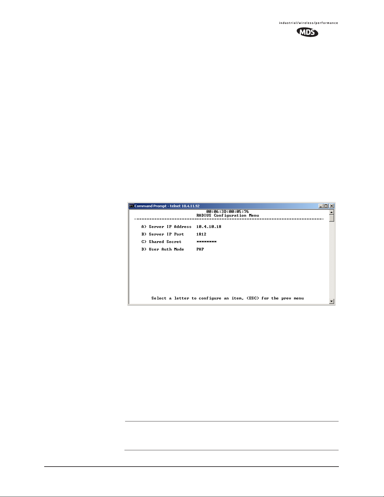
Remote: When Device Auth Method is set to RADIUS, the Remote halts any
data it is passing, and requests Authentication from the RADIUS Server.
If accepted, data is allowed to be transmitted.
Operation of User Authentication
When user authentication is set to
Local or RADIUS, you must enter a
valid user name and password before being allowed to manage the radio.
In
RADIUS mode both of these fields may be up to 40 characters long. In
Local mode the user name is admin and the password may be up to 8 char-
acters long.
When set to
RADIUS, all logins to the local configuration services are
required to be authenticated via the RADIUS Server, including telnet
and SSH (Secure Shell) sessions. Authentication must be accepted
before access to the radio menu is granted.
3.7.4 RADIUS Configuration
Invisible place holder
Figure 3-41. RADIUS Configuration Menu
• Server IP Address—Used to set/display address of the Server
where the RADIUS application resides.
•
Server IP port—1812 is the standard port for authentication (RFC
2865, June 2000) and should not be changed unless instructed
to do so by an administrator.
•
Shared Secret—User authentication and Device authentication
require a common shared secret to complete a RADIUS transaction. This entry must match the string used to configure the
appropriate files on the RADIUS Server.
•
User Auth Mode—Should be set to PAP or CHAP depending on
the configuration of the server.
NOTE: CHAP is the more secure mode when compared to PAP. PAP
may display the login password in log files at the RADIUS
Server. CHAP will encrypt the login password.
MDS 05-4446A01, Rev. A MDS Mercury User’s Guide 83
Page 92

NOTE: The security password may not exceed 40 characters in length.
3.7.5 Certificate Management (Remote transceivers only)
Use Certificate generation software to generate certificate files and then
install these files into each Remote unit via TFTP. The certificate files
must be in DER format. The Common Name (CN) field in the public
certificate file must match the serial number of the unit it will be
installed in.
Invisible place holder
Figure 3-42. Manage Certificates Menu
(NOTE: The appearance of this screen differs from the others because a different
terminal program was used; Menu content is the same regardless of program.)
• Server IP Address—the IP address of the Server where the
RADIUS application resides.
•
TFTP Timeout should be set appropriately according to the layout
of the network.
Three certificate files (Root, Client, and Private Key) must be present in
each of the Remote radios. Use the commands described below to install
these files into each Remote radio.
•
Certificate Filename—Used to specify the filename of the certifi-
cate file residing on the TFTP server.
•
Certificate Type—Selects one of the three file types mentioned
above. [
Root Certificate
Root Certificate, Client Certificate, Private Key Certificate;
]
• Retrieve Certificate—Initiates the retrieval of the certificate file
from the storage location. A successful installation issues a
plete
status message.
Com-
84 MDS Mercury User’s Guide MDS 05-4446A01, Rev. A
Page 93

NOTE: It is imperative that the three certificate files are installed
correctly into the Remote radio, in their respective file types.
If they are not, it will render the Remote un-authenticated for
data traffic. Consult your RADIUS network administrator if
issues arise.
3.8 PERFORMANCE VERIFICATION
After the basic operation of the radio has been checked, you may wish
to optimize the network’s performance using some of the following suggestions. The effectiveness of these techniques will vary with the design
of your system and the format of the data being sent.
There are two major areas for possible improvement—the radio and the
data network. The following sections will provide you with a variety of
items to check and on many occasions, ways to correct or improve their
performance.
3.8.1 Performance Information Menu
This menu/screen is one of two primary sources of information on the
radio layer and radio network performance.
Figure 3-43. Performance Information Menu
(AP Version Shown)
• RF Output Power (Display only)—Measured power output.
(See “How Much Output Power Can be Used?” on Page 144)
•
Signal-to-Noise (Display only)—Current running-average SNR
value all active operating frequencies.
(No value displayed on APs)
•
RSSI (Display only)—Current running-average Received Signal
Strength Indication for all active operating frequencies.
(No value displayed on APs.)
MDS 05-4446A01, Rev. A MDS Mercury User’s Guide 85
Page 94

• Actual Data Rate (Display only)—Over-the-air transmission rate (as
opposed to selected data rate) for the remote being monitored.
The fastest data rates can generally be achieved with stronger
signal levels.
•
RSSI by Zone—Received Signal Strength Indicator by Zone.
(See “RSSI by Zone Menu (Remotes Only)” on Page 86)
•
Event Log—Access the menu for managing the unit’s log of
operational activities.(See “Authorization Key—Alter the
unit’s overall capabilities by enabling the built-in resources.
(See “Authorization Keys Menu” on Page 116)” on Page 101)
•
Packet Statistics—Multiple radio and network operating statis-
tics. (See “Packet Statistics Menu” on Page 90)
•
Wireless Network Status (Displayed only at Remotes)—Current associ-
ation state and MAC address of the Access Point.
(See “Wireless Network Status (Remotes Only)” on Page 92)
•
Remote Listing (AP Display only) —List of basic information for all
Remote units currently associated with this Access Point.
(See “Remote Listing Menu (Access P oints Only)” on Page 93)
•
Endpoint Listing (AP Display only)—List of units accessible by this
AP through associated Remote ports.
(See “Endpoint Listing Menu (Access Points Only)” on
Page 94)
•
Remote Performance Listing (AP Display only)—(See “Remote Per-
formance Listing Menu (Access Points Only)” on Page 95)
RSSI by Zone Menu
(Remotes Only)
This screen displays the strength of RF signals received from the currently associated Access Point.
Network integrity depends in large part on stable radio signal levels
being received at each end of a data link. In general, signal levels
stronger than –80 dBm will provide reliable communication that
includes a 15 dB fade margin.
If you find there is a poor signal level on one zone, check the Packet Sta-
tistics Menu section on Page 90 and record the values. Then, set the
questionable zone to “Skipped” in the Radio Configuration Menu (Page
52) and look for an improvement in the Packet Statistics error rates. If
there is none, return the Zone to “Active.”
RSSI measurements and Wireless Packet Statistics are based on mul-
tiple samples over a period of several seconds. The average of these
measurements will be displayed by the Management System.
86 MDS Mercury User’s Guide MDS 05-4446A01, Rev. A
 Loading...