

Page 1
Train Chief® II LRCS
w/Lightweight OCU
(Brake &Throttle Industrial Version)
Failure to return the Warranty Registration document (enclosed) to
Control Chief within 30 days of purchase will void any warranty
responsibilities on behalf of Control Chief Corporation
Control Chief Corporation
200 Williams Street Bradford, PA 16701
814-362-6811 * 1-800-233-3016 * 814-368-4133
www.controlchief.com
(fax)
95-00-0-xxx-MAN
Page 2

Control Chief Corporation, a world leader in wireless radio and infrared
remote control products has developed and expanded upon this powerful
technology. More than three decades of experience in designing,
manufacturing and installing state-of-the-art remote communication
systems emphasize Control Chief’s mission.
Our systems are tailored to virtually any environment or application.
Control Chief provides training, technical support, and comprehensive
system design to maximize performance. It is our honor to uphold this
reputation of innovative engineering and superior product performance.
Publication: 95-00-0-xxx Rev 000
Copyright © 2010 Control Chief Corporation
All Rights Reserved.
200 Williams Street, Bradford, Pennsylvania, 16701
Web Page: www.controlchief.com
Telephone: (814) 362-6811, FAX: (814) 368-4133
TRAIN CHIEF® II is a registered trademark of Control Chief Corporation.
Communicator® is a registered trademark of Control Chief Corporation.
SLC 500™ is a trademark of Rockwell Automation.
PanelView™ is a trademark of Rockwell Automation.
Page 3

TRAIN CHIEF® II LRCS w/Lightweight OCU OWNER’S MANUAL
TABLE OF CONTENTS
CHAPTER 1 INTRODUCTION / SAFETY
Introduction 1-1
Common Acronyms 1-1
Receiver / Controller Unit (RCU) 1-1
Installation Kit 1-2
Lightweight Operator Control Unit (OCU-BTIND) 1-2
Reference Drawings 1-2
Safety 1-3
CHAPTER 2 SPECIFICATIONS
General Specifications 2-1
Lightweight OCU-DBT Specifications 2-1
RCU Specifications 2-1
CHAPTER 3 PHYSICAL DESCRIPTION AND INSTALLATION
The Lightweight OCU-BTIND 3-1
OCU-BTIND Control Groups 3-1
The RCU 3-7
RCU Mounting 3-13
Locomotive Interface 3-14
The Installation Kit 3-15
General Installation Practices 3-16
CHAPTER 4 START UP AND OPERATING PROCEDURES
Locomotive Stops (Definitions) 4-1
Brake Monitoring 4-2
Setup for Remote Control Operations 4-2
Transfer to Remote Control and PCS Reset 4-4
Air Brakes and Safety Features Test 4-5
Normal Locomotive Operation 4-6
Transferring from Remote to Manual 4-10
CHAPTER 5 OPTIONS
Special Features (Included Options) 5-1
OCU Two-Way Operational Messages 5-2
95-00-0-xxx Rev 000 i Control Chief Corporation
Page 4

TRAIN CHIEF® II LRCS w/Lightweight OCU OWNER’S MANUAL
CHAPTER 6 DETAILED COMPONENT DESCRIPTIONS
Lightweight OCU Features
IR Registration Process
OCU Controls
OCU Keypad, Indicators, and Display
Battery and Battery Charger Details
Typical; Locomotive Pneumatic Interfaces 6-10
CHAPTER 7 TROUBLESHOOTING
Lightweight OCU Troubleshooting 7-1
Transmitter Diagnostics 7-2
SLC 500™ Troubleshooting 7-5
Control Chief Specific PLC Modules 7-7
Troubleshooting Communications Faults 7-9
Electrical and Pneumatic System Troubleshooting 7-10
6-1
6-2
6-2
6-6
6-9
CHAPTER 8 PRODUCT SUPPORT & SPARE PARTS
Product Support 8-1
Returning OCU for Repair 8-1
Contacting Control Chief 8-1
Spare Parts and Accessories 8-2
CHAPTER 9 DETAILED MAINTENANCE PROCEDURES
Locomotive Antenna System 9-1
Pneumatic Filter Service Instructions 9-1
OCU Lithium-Ion Battery Maintenance 9-2
Control Chief Recommended Training Outline 9-3
95-00-0-xxx Rev 000 ii Control Chief Corporation
Page 5
TRAIN CHIEF® II LRCS w/Lightweight OCU OWNER’S MANUAL
1 INTRODUCTION / SAFETY
Introduction
This Owner’s Manual provides operating and troubleshooting information for the installer and
end user of the Train Chief® II Locomotive Remote Control System (LRCS) with a Lightweight
Operator Control Unit (OCU) Brake & Throttle variant for Industry (BTIND).
The Train Chief® II LRCS has been designed as a permanently installed (“fixed”) system,
directly interfaced to the appropriate locomotive electrical and pneumatic controls. The system
consists of the following main components: (1) - the Receiver / Controller Unit (RCU), (2) - the
wireless remote-control radio OCU, (3) - the installation kit.
Common Acronyms
CFR - Code of Federal Regulations RCL - Remote Control Locomotive
FRA - Federal Railroad Administration RCO - Remote Control Operator
LRCS - Locomotive Remote Control System RCU - Receiver / Controller Unit
OCU - Operator Control Unit RCT - Remote Control Transmitter
PTC - Positive Train Control RCR - Remote Control Receiver
PLC - Programmable Logic Controller
Receiver / Controller Unit
The RCU contains the main control electronics and pneumatic hardware of the remote control
system. This includes; the PLC controller (the Allen Bradley SLC 500™), the Control Chief
Communicator® module and Control Chief Watchdog module, analog and discrete interface
modules, pneumatic proportional control valves, air regulation, control relays, solenoid valves,
and pressure sensing devices.
The RCU interface to the locomotive involves both
electrical and pneumatic connections. The
electrical interface is primarily accomplished
through DC relay contact closures, wiring into the
locomotive’s existing electrical control system. The
pneumatic interface typically involves direct air
service tie-ins using the dedicated pneumatic
control devices in the RCU. A dedicated DC/DC
converter and line conditioning module are
provided to interface the locomotive’s existing DC
supply to the RCU.
Figure 1-1 – The Receiver / Controller Unit
95-00-0-xxx Rev 000 1-1 Control Chief Corporation
Page 6
TRAIN CHIEF® II LRCS w/Lightweight OCU OWNER’S MANUAL
The Installation Kit
In order to effectively and reliably interface to the locomotive controls / operations, various kitted
items are provided to complete the installation. An antenna kit is provided with the components
necessary to allow the radio antenna to be mounted on the locomotive cab. Surge suppressors
are provided for installation on all inductive devices (i.e. solenoid coils, electrical contactor coils,
etc.) to minimize electro magnetic interference (EMI). Optional color-coded xenon strobe
indicator lights can be supplied to provide visual status indication to personnel during remote
control operation.
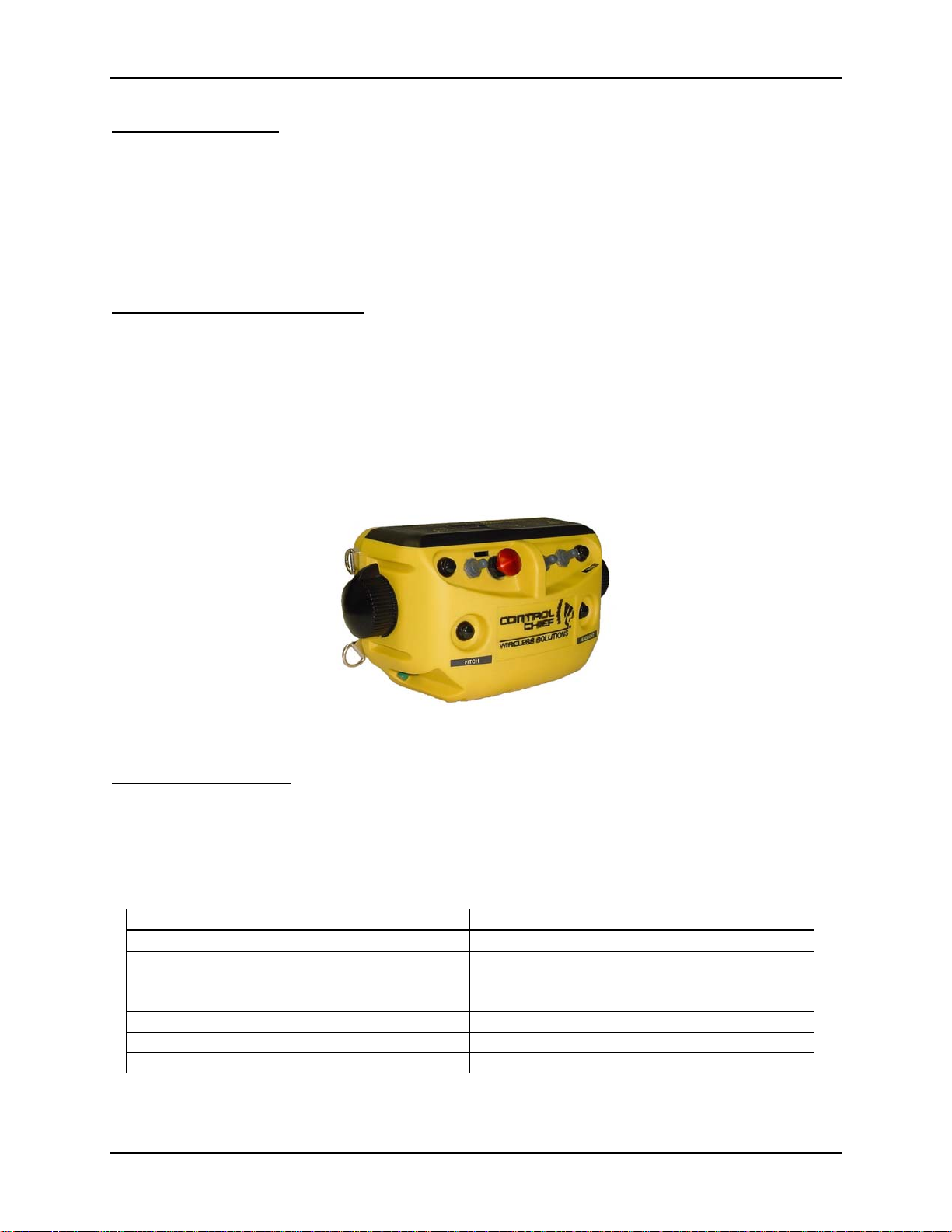
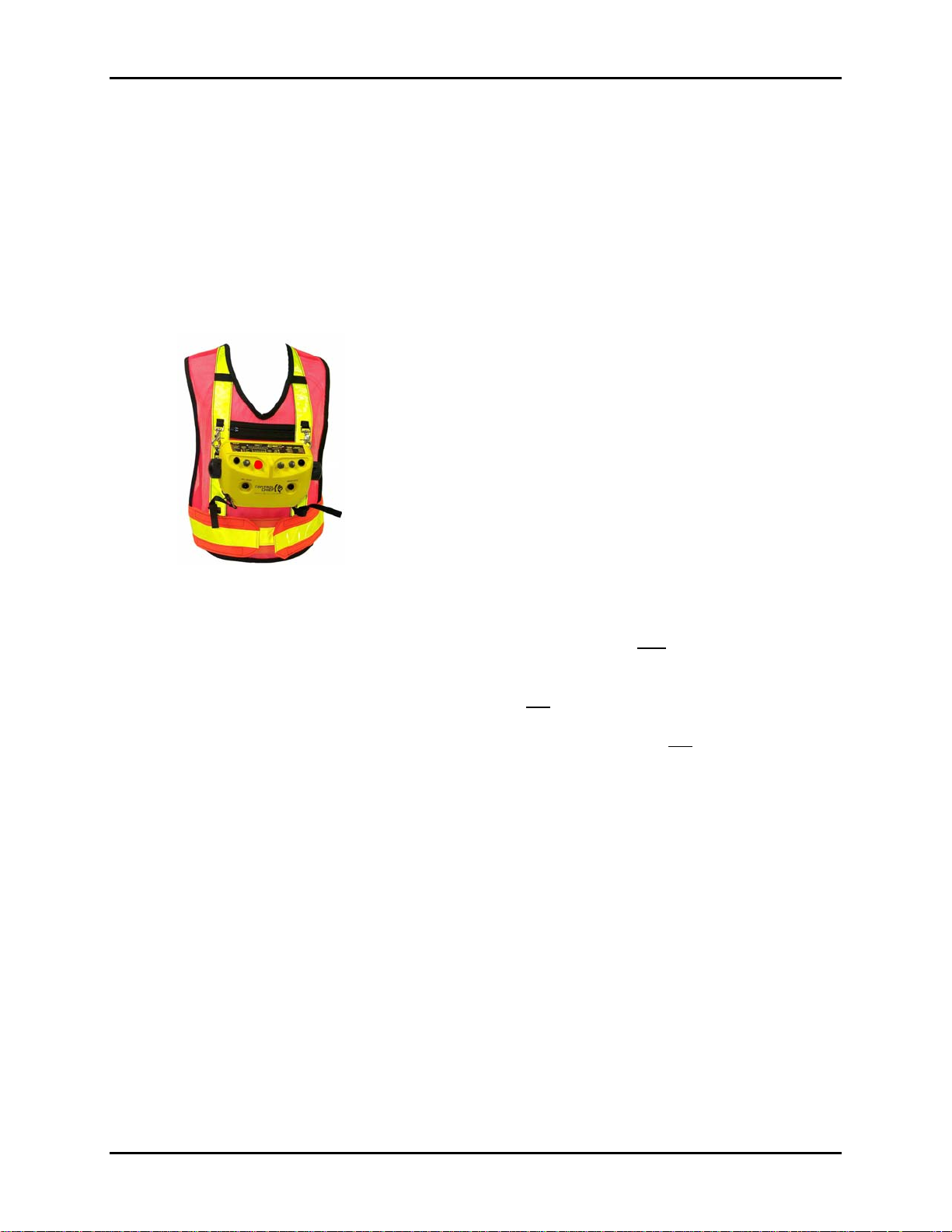
The Lightweight OCU-BTIND
The Lightweight OCU model DBT is specifically designed for industrial locomotive operations.
The model DBT is designed to meet the demanding requirements of locomotive operators by
providing an operator control unit that is easy to use, safe, rugged, dependable, and based on a
commonly recognized configuration. The Lightweight OCU meets these requirements with an
ergonomic shape that eliminates sharp corners and accommodates an easy reach of all control
switches. These features provide an intuitive operation scheme enabling operators to maintain
their focus on yard movements.
Figure 1-2: Lightweight OCU –Brake & Throttle Industrial configuration
Reference Drawings
The system drawing package contains the following typical drawings, which are referenced
throughout this document. These drawings will be specific to your system with exact
configuration details.
Note: “XXXX” references a Control Chief assigned system serial number.
Typical Drawing List
DRAWING NUMBER DESCRIPTION
E-9568-00-1 OCU ASSEMBLY / LAYOUT
E-9568-03-1 RECEIVER / CONTROLLER LAYOUT
E-9568-31-1 THRU -9
E-9568-33-1 AND E-9568-41-1 ELECTRICAL WIRING
E-9568-53-1 PNEUMATIC INTERFACE
E-9568-91-1 SYSTEM ACCESSORIES
E-9568-99-1 COMMUNICATIONS CONFIGURATION
95-00-0-xxx Rev 000 1-2 Control Chief Corporation
Page 7

TRAIN CHIEF® II LRCS w/Lightweight OCU OWNER’S MANUAL
Safety
The safety guidelines in this manual are not intended to replace any rules or regulations or any
applicable local, state, or federal governing laws. The following information is to be used in
conjunction with all other rules and/or regulations already in existence. It is important to read all
safety information before operating any wireless radio remote control system. The Federal
Railroad Administration (FRA) has published a Notice of Safety Advisory 2001-1 (in the
Federal Register, Vol 66, #-31, Pg. 10340) addressing the establishment of recommended
minimal guidelines for the operation of remote control locomotives. A copy of all referenced FRA
regulations can be obtained directly from the FRA or contact Control Chief for help in obtaining
a copy of these regulations.
The term “Remotely Controlled Locomotives” or “Remote Control Locomotives” (RCL) refers to
a locomotive, which, through use of a wireless radio operator control unit and receiver system,
can be operated by a person not physically located at the controls within the confines of the
locomotive cab. The wireless Remote Control Operator (RCO) must exercise extreme caution
and be alert at all times.
Only properly trained persons (certified and qualified in accordance with 49 CFR Part 240, as
conventional operation of a locomotive under the same circumstances would require) should be
operating RCLs. RCLs should not be operated by any person who cannot read or understand
signs, notices and operating instructions that pertain to the locomotive operation.
Any person operating a remote controlled locomotive should possess the following knowledge
and/or skills:
Current certification on methods of safe train handling, operating rules, conditions of
equipment, personal safety practices
Knowledge/training on hazards specific to locomotive operation
Knowledge/training of safety rules for RCLs
Knowledge of the radio transmitter/receiver equipment/system
Knowledge/training on all required inspections and testing
Knowledge on transferring control from one operator to another
Reporting unsafe or unusual operating conditions
Upon going off duty, each RCO should place the RCL in manual operation and properly secure
it and the OCU to prevent unauthorized operation. The recommended practice for OCU security
includes the designation of a dedicated, lockable location for OCU storage, which can have
access controlled to only appropriately trained / knowledgeable personnel.
When operating a RCL, the RCO should NOT:
Ride on a freight car under any circumstances
Mount or dismount moving equipment
Operate any other type of machinery
Stand or walk within the gage of the track or foul the track on which the movement is
occurring
When the using the OCU the RCO should always wear a 4-point breakaway vest.
RCOs should ensure that the track is clear and properly aligned ahead of the remotely
controlled movement. Therefore, RCL operations should be operated at restricted speed not to
exceed a speed that will enable stopping the movement within half the range of vision assuring
that all movements are protected.
95-00-0-xxx Rev 000 1-3 Control Chief Corporation
Page 8

TRAIN CHIEF® II LRCS w/Lightweight OCU OWNER’S MANUAL
Strict procedures must be followed to ensure that there can only be one RCT in active
control of the RCL at any one time.
Prior to performing any function (as prescribed in 49 CFR 218.22.c.5) the RCO should apply
three-point protections; (1) fully apply the locomotive and train brakes, (2) center the reverser,
and (3) place the generator field switch to the OFF position.
Passenger trains should NOT be operated by use of a remote control device.
The following security procedures are recommended:
Have instructions for the proper storage, handling and security of RCTs when not in use or
in the operator’s possession.
Operation control handles located in the RCL cab should be removed or pinned in place to
prevent accidental or intentional movement while the RCL is being operated in remote.
Have strict procedures in place to ensure that only the intended RCT is assigned to the
appropriate RCL.
All inspections and calibrations must be performed as required.
Each RCL should have a tag placed on the control stand throttle indicating the locomotive is
being used in a remote control mode. The tag should be removed when the locomotive is
placed back in manual mode.
In areas where RCL operations are being conducted, warning signs should be posted indicating
that there are remote control locomotives in use. These warning signs should be highly visible
and posted at conspicuous locations so as to maximize their exposure to those most likely to
encounter RCL operations.
Whenever worker protection is required (according to 49 CFR Part 218) the locomotive should
be placed in manual mode and be properly secured. The appropriate blue signal protection
should then be provided.
All accidents and/or incidents (described in 49 CFR Part 225) must be reported to FRA using
the appropriate “remote control” reporting codes.
CAUTION
THE RECEIVER UNIT OR RELAYS ARE NOT RATED AS EXPLOSION PROOF. THE
RECEIVER UNIT MUST NOT BE INSTALLED OR OPERATED IN EXPLOSIVE
ENVIRONMENTS UNLESS APPROPRIATE SECONDARY ENCLOSURE MEASURES ARE
TAKEN.
WARNING
THE UNIT MUST BE WIRED TO THE CORRECT VOLTAGE; FAILURE TO DO SO MAY
DAMAGE THE SYSTEM.
NOTE
IN AN EMERGENCY, PUSH “E-STOP” TO STOP WIRELESS RADIO CONTROLLED
EQUIPMENT
The antenna(s) to be used with this module must be installed with consideration to the
guidelines for RF exposure risk to all nearby personnel, and must not be co-located or operating
in conjunction with any other antenna or transmitter.
95-00-0-xxx Rev 000 1-4 Control Chief Corporation
Page 9
TRAIN CHIEF® II LRCS w/Lightweight OCU OWNER’S MANUAL
2 SPECIFICATIONS
WARNING:
CHANGES OR MODIFICATIONS NOT EXPRESSLY APPROVED BY
!
FCC Part 15 and Industry Canada RSS Notice
This device complies with Part 15 of the FCC Rules and Industry Canada licenseexempt RSS standard(s). Operation is subject to the following two conditions: (1)
this device may not cause interference, and (2) this device must accept any
interference that may cause undesired operation of the device
RSS FCC Partie 15 et du Canada Avis à Industrie
Cet appareil est conforme à la Partie 15 des règlements de la FCC et Industrie Canada
exempts de licence standard RSS (s). Son fonctionnement est soumis aux deux
conditions suivantes: (1) cet appareil ne peut pas provoquer d'interférences et (2) cet
appareil doit accepter toute interférence pouvant causer un mauvais fonctionnement du
CONTROL CHIEF® CORPORATION COULD VOID THE USER’S
AUTHORITY TO OPERATE THE EQUIPMENT.
The Control Chief Lightweight OCU Family model(s) comply with FCC and Industry
Canada RF exposure requirements when used as described in this manual. Only use
authorized accessories to hold the device to the body while operating the device.
Le contrôle en chef léger OCU famille modèle (s) se conformer à la FCC et exigences
d'Industrie Canada d'exposition RF lorsqu'il est utilisé comme décrit dans ce manuel.
N'utilisez que des accessoires autorisés à placer l'appareil sur le corps pendant le
fonctionnement du dispositif.
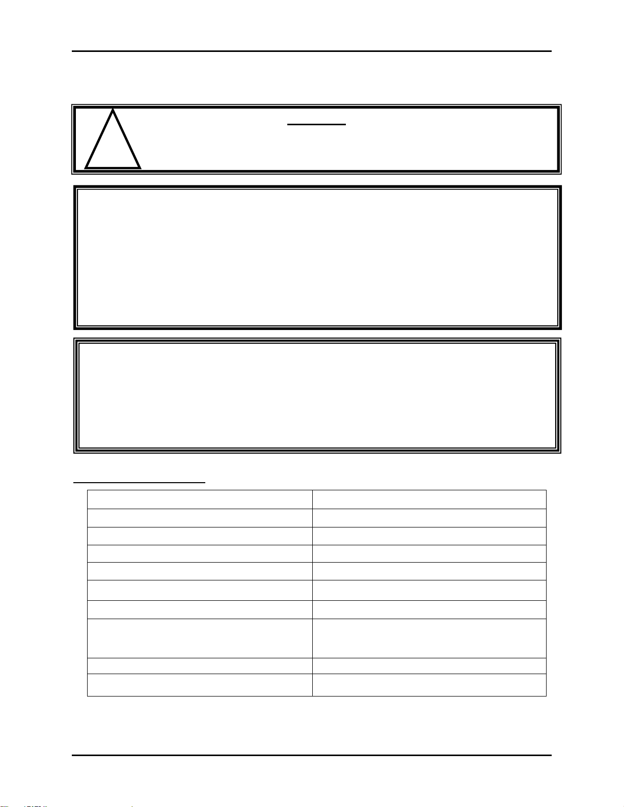
General Specifications
Frequency 902-928 MHz (FCC Part 15)
Operating Range 2500 feet (1.06km) environment dependent
Temperature Range -20 to +140 F (-30 to +60 C)
System Diagnostics Various LED indicators
System Address Capacity 65,000 +
Encoding/Decoding Method Microprocessor/software based
Data Security Real time 16 bit CRC
OCU registers with Locomotive via Infra-Red
Communication Security
Modulation CPFSK (Continuous Phase Freq Shift keying)
communication port to exchange and
establish RF network addresses
Response Time 250 milliseconds
95-00-0-xxx Rev 000 2-1 Control Chief Corporation
Page 10

TRAIN CHIEF® II LRCS w/Lightweight OCU OWNER’S MANUAL
Lightweight OCU Specifications
Dimensions
Weight 3.9 lbs (1.8 Kg) with battery
Carrying Method Four point vest-harness, break-away style
Environmental Conditioning Weatherproof (IP-65)
OCU Diagnostics 2-line 16 character display
Switches Push buttons, toggle switches, knobs.
Supply Voltage
Battery Life 12 hours continuous duty
RF Power Output 1 watt
Antenna Type Internal, Di-pole
6”(h) x 5”(d) x 10”(w)
(15.2cm x 12.7cm x 25.4cm)
7.4 V Lithium-Ion rechargeable battery
pack
Receiver / Controller Specifications
Enclosure NEMA 12 dust tight
Weight Approximately 95 lbs (~36 Kg)
Dimensions 30.0 x 20.0 x 11.0” (76.2 x 51 x 30 cm)
Electrical Interface Connection Various cable connections
Pneumatic Interface Connection Various push-in type tubing connections
Mounting Provisions Top/bottom tabs @ 16” centers
Power Source Required Locomotive DC supply
Pneumatic Source Required
Due to Control Chief Corporation’s commitment to continuous improvement, the above
specifications are subject to change without notice.
Locomotive main air reservoir; Max 150 psig
Min 90 psig
95-00-0-xxx Rev 000 2-2 Control Chief Corporation
Page 11
TRAIN CHIEF® II LRCS w/Lightweight OCU OWNER’S MANUAL
r
3 PHYSICAL DESCRIPTION AND INSTALLATION
The Lightweight OCU-BTIND
Train Chief® II equipped locomotives are controlled by using one or two Lightweight OCU’s.
Each OCU is a small 3.9 lb hand operated device that gives an operator complete throttle and
braking control of the locomotive up to 2500 feet away. Control of the locomotive can be
passed between two OCU’s when the optional Selective Dual Control feature is installed.
OCU Control Groups
The OCU has controls for:
1. Movement commands (direction, throttle and braking)
2. Miscellaneous locomotive commands (bell, horn, bail and sand)
3. OCU operations (power, reset, status, pitch, tilt time extend)
It also has visual and audio signals indicating the status of commands to the locomotive and
OCU operational status.
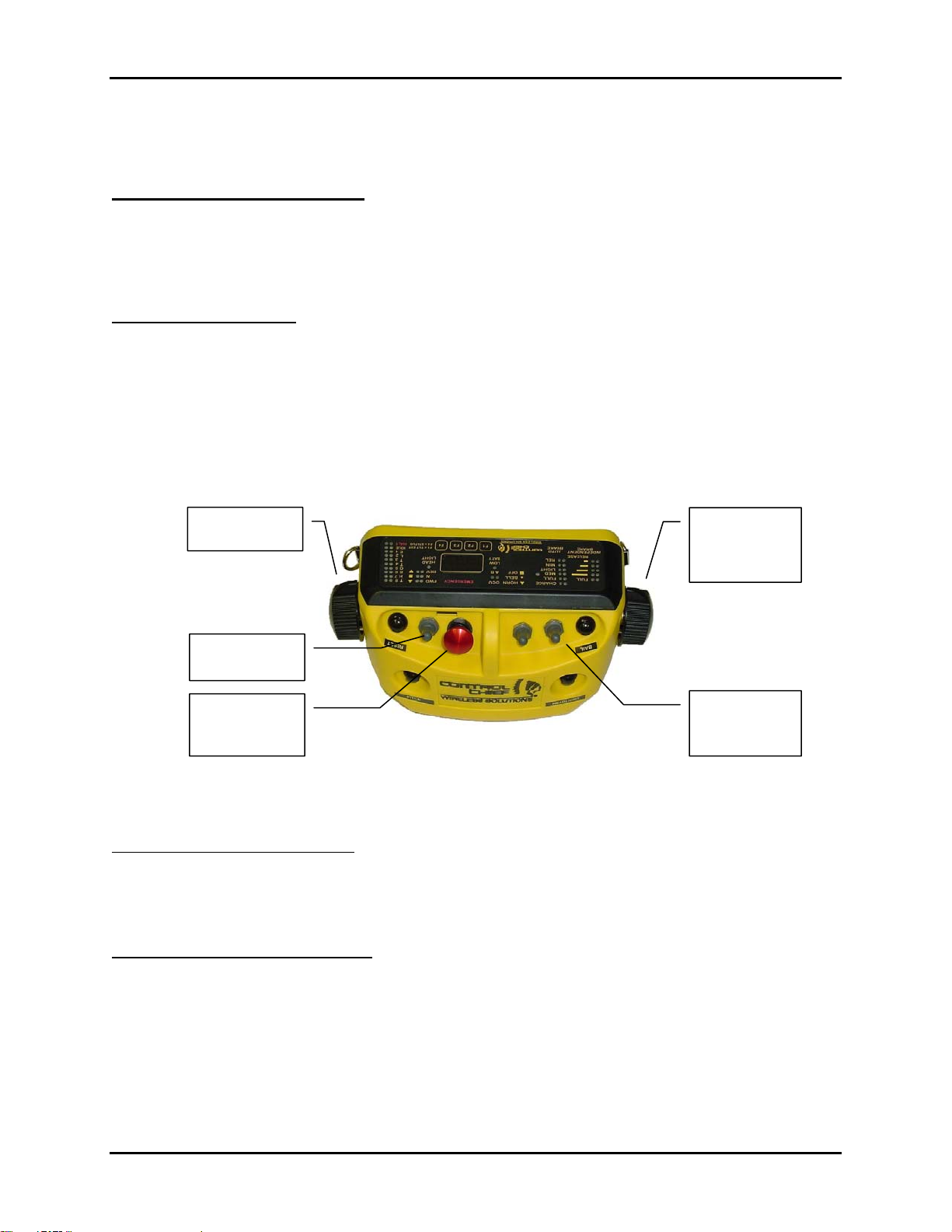
Movement Controls
Throttle
Selecto
Independent
Brakes
(Locomotive)
Reverser
Selector
EMERGENCY
Mushroom
Switch
Automatic
Brakes
(Train)
Figure 3-1: Lightweight OCU-BTIND Movement Controls
Reverser (Directional) Selector:
This 3-position switch selects locomotive movement direction
as Forward, Reverse, or Neutral.
Note: Train Chief® II does not allow you to change the direction of movement while the
locomotive is in motion. If attempted, Train Chief® II will automatically stop the
locomotive by commanding a Full-Application Locomotive Stop (see page 4-1).
EMERGENCY Mushroom Switch: Push in to activate an Emergency Locomotive Stop. See
page 4-1 for E-Stop actions. For normal operations the EMERGENCY switch must be pulled
out.
Note: E-Stop develops high brake cylinder pressures that increase the chance of sliding
wheels. Only use the EMERGENCY mushroom switch when absolutely necessary.
95-00-0-xxx Rev 000 3-1 Control Chief Corporation
Page 12

TRAIN CHIEF® II LRCS w/Lightweight OCU OWNER’S MANUAL
Throttle Selector: Ten-position selector represents the throttle position available in the cab.
However, one additional feature of the OCU throttle is the HALT function.
• HALT: commands the throttle to idle, removes the generator field, and also gradually
applies independent brakes.
• IDLE: commands throttle to idle and removes generator field but does not apply brakes.
• The remaining positions, 1 through 8, command the same throttle settings as the control
cab console settings.
Automatic Brakes:
apply train brakes by reducing
This 3-position spring centered switch allows the operator to release or
brake pipe by the following pressures:
• Release 0-psi reduction
• Minimum 6-8 psi reduction
• Light 10 psi reduction
• Medium 18 psi reduction
• Full 26 psi reduction
• The Charge position is used to pressurize the air brake system.
The center switch position (LAP) maintains the last brake setting.
Each time the switch is pressed (must be held for 0.5 sec) the train brakes are incremented to
the next higher/lower setting.
On the First application of Auto Brake the locomotive brake portion of the train brake application
is automatically bailed off.
Whenever the switch is pulled (must be held for 2 sec) the train brakes immediately revert back
to Release position.
Independent Brakes:
This 6-position selector allows the operator to apply independent
locomotive brakes to achieve the desired stopping power. Some positions limit and override the
throttle control.
Selectable positions are:
• Release (0 psi): this is the normal operating position when operating in power mode
(Throttle positions 1-8). (Note RELEASE selection is indicated when all Independent
Brake LEDs are off.)
• B1: Applies 1/5 of the available independent brake pressure to the brake cylinders.
Throttle selections T1 to T8 are allowed.
• B2: Applies 2/5 of the available independent brake pressure to the brake cylinders.
Throttle selections T1 to T8 are allowed.
• B3: Applies 3/5 of the available independent brake pressure to the brake cylinders.
Throttle selections T1 to T3 are allowed. See notes 1 and 2.
• B4: Applies 4/5 of the available independent brake pressure to the brake cylinders.
Throttle selections T1 to T3 are allowed. See notes 1 and 2.
• FULL: Applies total available independent brake pressure to the brake cylinders.
Throttle selections T1 to T3 are allowed. See notes 1 and 2.
NOTE 1: If throttle is advanced T4 to T8 the default programming will reduce throttle to IDLE.
To recover throttle operations return throttle selector to IDLE.
NOTE 2: The threshold parameters for limiting throttle vs. brake settings B1 to FULL can be
adjusted per owners’ operating rules and requirements.
95-00-0-xxx Rev 000 3-2 Control Chief Corporation
Page 13
TRAIN CHIEF® II LRCS w/Lightweight OCU OWNER’S MANUAL
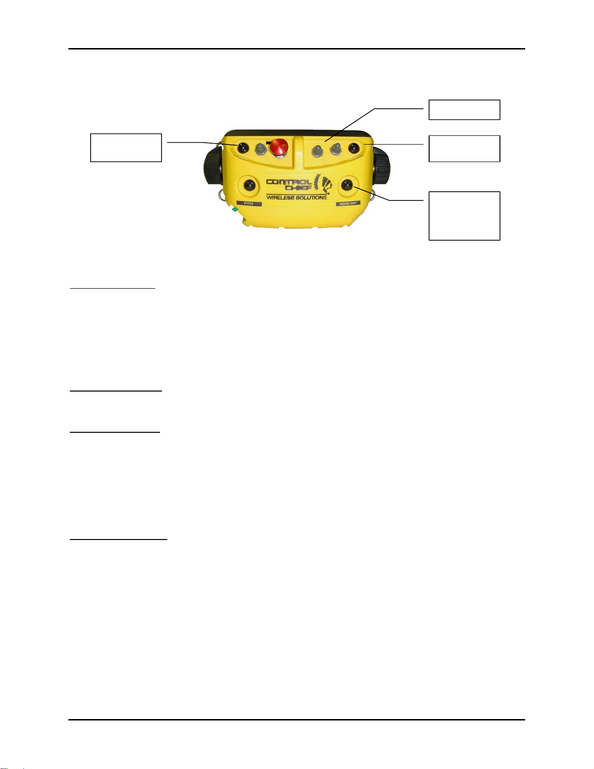
Misc. Locomotive Controls
Bell / Horn
Reset & Sand
Reset & Bail
Optional
Functions:
Headlight or
Tilt Extend
Figure 3-2: Lightweight OCU-BTIND
Bell / Horn switch:
This is a 3-positon switch. It is latched at the rear (OFF) position and at the center (BELL)
position. The forward (HORN) position is spring loaded to return to BELL position when
released. Return the switch to the OFF position to silence the Bell.
1. Bell function only: whenever the locomotive is stopped and the Throttle Selector is moved
from Halt to some movement position, Train Chief® II sounds the bell for 5 seconds.
2. Horn function only: The horn function is also used to acknowledge or accept a “Pitch”
from a transferring OCU.
Optional Functions: (OCU-BTIND only)
This button can control headlights or act as an additional TILT EXTEND button. See Chapter 5
for full description of options.
Reset / Bail button:
When depressed briefly the button acts as a RESET for several functions.
1. It resets the ALERT warning. See page 4-7 for description of ALERT function.
2. It allows the RCU to allow a brake release when the operator moves the Throttle selector
out of the HALT position.
When depressed for longer than 2 seconds the second function of BAIL is activated. The BAIL
function allows the independent brakes to be released while the train brake continues to be
applied.
Reset / Sand button:
When depressed briefly the button acts as a RESET for several functions.
1. It resets the ALERT warning. See page 4-7 for description of ALERT function.
2. It allows the RCU to allow a brake release when the operator moves the Throttle selector
out of the HALT position.
When depressed for longer than 2 seconds it activates the sanders in the direction of
movement.
95-00-0-xxx Rev 000 3-3 Control Chief Corporation
Page 14
TRAIN CHIEF® II LRCS w/Lightweight OCU OWNER’S MANUAL
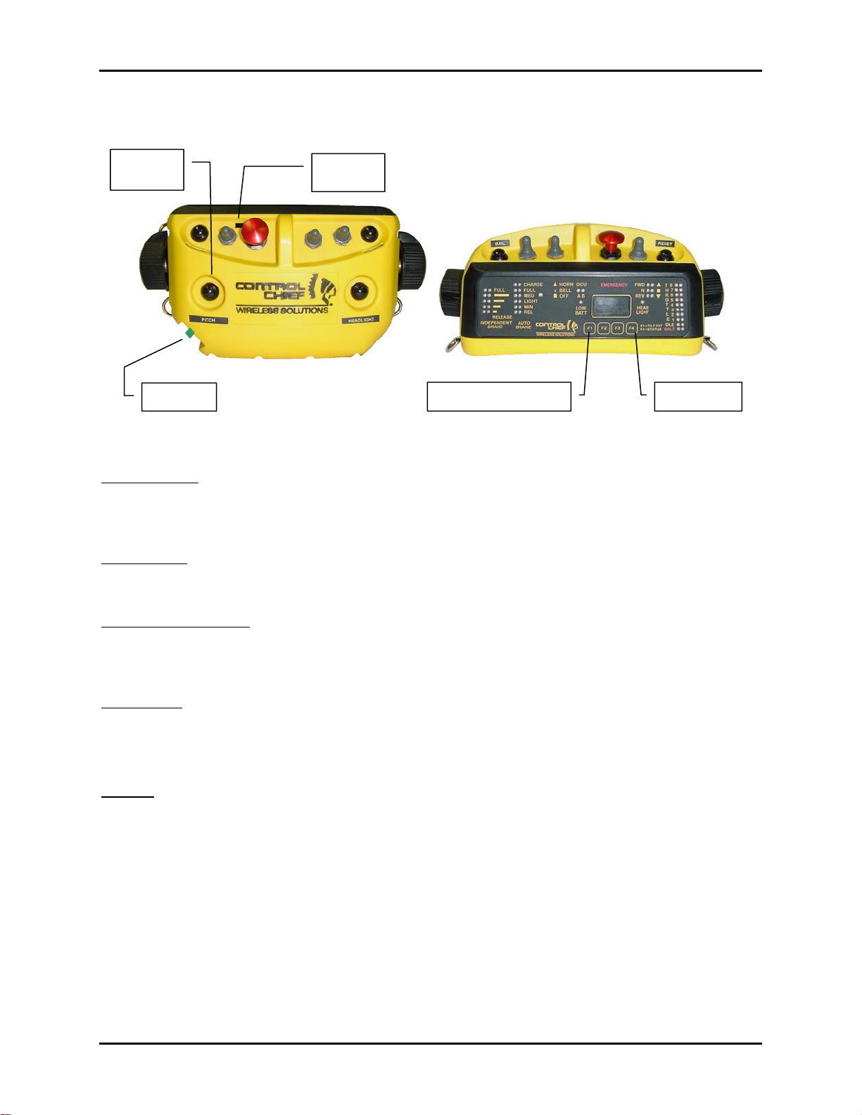
OCU Operation Controls and Associated Functions
Pitch
IR Port
Power
Tilt Time Extend (F1) Status (F4)
Figure 3-3: Lightweight OCU-BTIND Controls
Power Button:
Push-On / Push-Off switch to apply power to the OCU. Power is supplied from the battery pack
and the power bridge. Depending on the charge state of the power bridge, the OCU may
activate for a short time without an installed battery. See page 6-2.
Pitch button:
The PITCH button is used to transfer movement control of the locomotive from one OCU to
another. Refer to page 4-2 in this manual describing the Selective Dual Control feature.
Tilt Time Extend (F1):
The Tilt Time Extend button extends the allowable tilt time to 60 seconds. To activate this
command the operator must depress the F1 button for 2 seconds until the OCU beeps to
acknowledge the command.
Status (F4):
Depressing the F4 key causes the OCU to initiate a status report from the locomotive or activate
a status menu that will be shown on the OCU display. Refer to the OCU display section on
page 6-8 for more details.
IR Port:
The IR port is used when registering the OCU to the locomotive. Aligning the IR ports of the
OCU and RCU during setup allows specific information to be exchanged between them. This
creates a secure communications link between them for the duration of the remote control
session. See Chapter 4 for complete registration procedures.
95-00-0-xxx Rev 000 3-4 Control Chief Corporation
Page 15
TRAIN CHIEF® II LRCS w/Lightweight OCU OWNER’S MANUAL
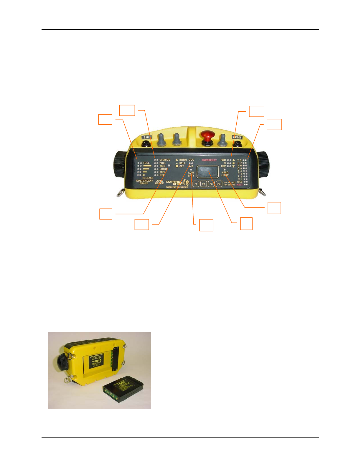
OCU Keypad, Indicators and Display
The location of the LEDs, Character-display, and Intensity sensor are shown in the diagram
below. All LEDs will illuminate during the power on sequence to allow detection of inoperative
LEDs.
B
A
J
G
C
D
E
F
Figure 3-4: Display Panel for Brake-Throttle Unit
[A] Independent Brakes [E] Headlight Bright Indicator
[B] Auto Brakes [F] 16 Character Display
[C] Reverser [G] Low Battery Indicator
[D] Throttle [H] OCU A / B Indicator
[J] Ambient Light Sensor
Steady LEDs at the respective locations in the above figure show the selected positions of the
OCU controls.
Battery Compartment
The 7.4 volt Lithium-Ion battery is secured in the
compartment by its own locking lip and does not require
a latching cover. Additional details are described on
page 6-1.
Fig 3-5: Battery and Battery Well
95-00-0-xxx Rev 000 3-5 Control Chief Corporation
Page 16
TRAIN CHIEF® II LRCS w/Lightweight OCU OWNER’S MANUAL
OCU Harness
The harness system is an integral part of the LRCS. With the many situations encountered in
rail equipment operations it is imperative the OCU does not constantly occupy an operator’s
hands. Control Chief has combined the OCU support harness with a high visibility safety vest to
avoid the operating gear and safety gear conflicts that are sometimes present when having to
don separate items.
• The Control Chief Break-away Safety Vest uses hookand-loop material at the shoulders and waist belts to be
easily opened and release the operator in the event of
being entangled.
o The hook and loop fabric also allows size
adjustment for secure fit and carry of the OCU.
• The vest should be kept clean to maintain high
visibility.
o Hand cleaning with mild detergent soap (non-
abrasive) or citrus cleaner is recommended.
o The vest can be machine washed with common
laundry detergents but useful service life will be
Fig 3-6
Breakaway Safety Vest
with Integral Harness
reduced.
o Use of petroleum solvents (diesel fuel,
kerosene, alcohol) is not
o Use of chlorinated cleaners (bleach, powders,
etc) is not
o Use of machine dryers is not
recommended.
recommended.
recommended.
95-00-0-xxx Rev 000 3-6 Control Chief Corporation
Page 17
TRAIN CHIEF® II LRCS w/Lightweight OCU OWNER’S MANUAL
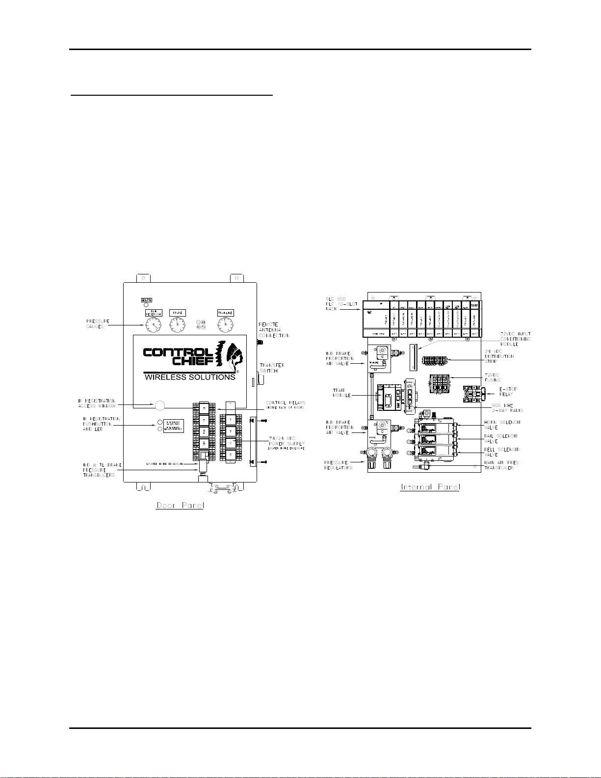
The Receiver / Controller Unit (RCU)
The RCU consists of the control electronic and pneumatic components. The electronic
components consist of the programmable logic controller (the SLC 500™ PLC) with various I/O
and specialty modules, the transfer switch and various DC relays. The pneumatic components
consist of proportional air control valves, solenoid ON/OFF valves, pressure switches, pressure
transducers and pressure regulators, all mounted on specifically designed manifolds. The RCU
is mounted inside the locomotive cab on a dedicated rail system (Unistrut). The RCU is then
interfaced to the locomotive system(s) via cable wiring and DOT rated plastic tubing as per the
specific pneumatic and electrical requirements.
For more details on the configuration of your system please refer to your system drawing
package, specifically, drawing number E-9568-03-1 RECEIVER / CONTROLLER LAYOUT.
32>(5
$//(1%5$'/(@
www.controlchief.com
1<0$7,&6 1<0$7,&6
+251
5
%$,/
5
%(//
5
(6
Figure 3-7: Typical RCU Layout
Transfer Switch, Intermediate Relays and DC Conditioning Module
The transfer switch is used to select between MANUAL and REMOTE operations. This switch
utilizes a switch-block arrangement that allows for various hardwired control functions.
The intermediate relays are used to control a number of auxiliary electrical devices such as
status lights, horn, sanding, and others depending on the locomotive requirements. The
intermediate relays may be located inside the enclosure or on the enclosure door. Refer to your
system prints for details specific to your system.
The DC conditioning module is used to condition the wheel slip and E-Stop inputs from 74VDC
down to 24VDC prior to going to the PLC input module. A DC-to-DC solid state isolated
voltage converter is provided to reduce the locomotive DC battery voltage to regulated 24VDC.
95-00-0-xxx Rev 000 3-7 Control Chief Corporation
Page 18

TRAIN CHIEF® II LRCS w/Lightweight OCU OWNER’S MANUAL
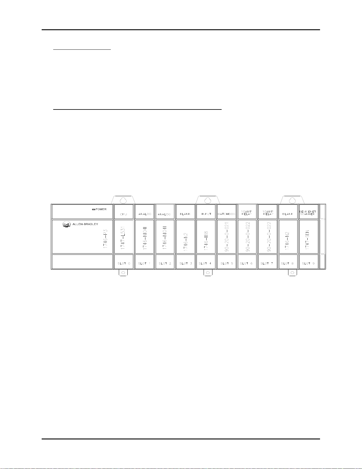
Programmable Logic Controller - SLC 500™System
The SLC 500™ is the control center for the Train Chief® II system. The SLC 500™ incorporates
the necessary I/O modules to control the various locomotive interfaces based on a ladder logic
program, specifically, developed for locomotive remote control and tuned for your particular
application.
1746-P3 POWER SUPPLY
Allen-Bradley SLC 500™ power supply modules include a LED that illuminates when the
power supply is functioning properly. Power supplies are designed to withstand a brief
power loss (brown-out) for a period of between 0.02 to 3 seconds, depending upon loading
conditions. The P3 fuse is accessible by opening the module’s front panel located to the
upper left of the input terminal block. A replacement fuse can be obtained from your local AB
distributor or through Control Chief Customer Service.
CHASSIS
The chassis houses the P3 power supply, processor, and all the I/O modules. All
components slide easily into the chassis along guides formed into the chassis. No tools are
required to insert or remove the processor or I/O modules. The power supply and removable
terminal strips on the I/O modules do require a philips screwdriver for removal and
installation.
SLC 500™ PROCESSOR
The SLC 500™ processor utilized in the Train Chief® II system contains the primary control
program. The processor is programmed using ladder logic which is uniquely suited for
control applications. For troubleshooting purposes the processor provides several LED
indicators; RUN, FAULT, and BATT (other modules will have additional indicators, but the
ones listed are the most important).
MEMORY MODULE
The memory module is a plug-in to the processor module and provides non-volatile and
secure program storage for the specific ladder program for your particular application.
ANALOG MODULE(S)
The analog modules incorporate high-resolution providing for precision control of analog
outputs, which are typically used to control the proportional pneumatic valves for locomotive
brake, trainline brakes, and where applicable, pneumatically controlled locomotive throttle.
The modules also incorporate high resolution inputs to precisely monitor the controlled
pressures. The modules feature input filtering providing high immunity to electrical noise.
OUTPUT MODULE(S)
The output module(s) provide the means with which to actuate the various functions on the
locomotive system. Typical functions controlled by the output modules include; generator
field, reverser directional selection, sand, horn, bell, throttle position, and indicator
lights/strobe. Intermediate relays are used (located in the locomotive interface panel) where
a control function current rating may exceed the rating of an output module. All output
modules provide LED indicators for each output point. The LED’s illuminate when the
processor applies power to an output terminal.
95-00-0-xxx Rev 000 3-8 Control Chief Corporation
Page 19
TRAIN CHIEF® II LRCS w/Lightweight OCU OWNER’S MANUAL
INPUT MODULE(S)
The input module(s) provide a means to monitor critical functional states of the locomotive
system. Typical system parameters monitored are the manual throttle, manual reverser,
external E-Stop switches, pressure switches, and wheel slip. The module features input
filtering, optical isolation, and built-in surge protection. All input modules provide LED
indicators for each input point. The LED’s illuminate when the proper signal is received at an
input terminal.
REMOTE CONTROL WITH ALLEN-BRADLEY SLC 500™
SLC 500™ remote control is facilitated by the implementation of Control Chief’s
Communicator® module and Watchdog relay module. This advanced technology is a result
of Control Chief’s partnership with Rockwell Automation to develop remote control capability
for the SLC 500™. The following paragraphs discuss how the remote control capability is
implemented in the Train Chief® II system providing safe and reliable operation.
Figure 3-8: SLC 500™ PLC
95-00-0-xxx Rev 000 3-9 Control Chief Corporation
Page 20

TRAIN CHIEF® II LRCS w/Lightweight OCU OWNER’S MANUAL
WATCHDOG SYSTEM
Remote control systems based on the SLC 500™ controller with the Communicator®
module will utilize a multiple feature watchdog safety system. The first watchdog circuit is
built into the wireless Communicator® module and monitors the operation of the module
CPU. Should this watchdog time out, then an automatic interrupt is generated which faults
the SLC 500™ CPU and clears all SLC output tables. An additional watchdog feature within
the module will clear the module I/O image table if communication with the remote unit is
lost.
The High Current Relay/Watchdog module incorporates two (2) additional watchdog safety
systems. Each watchdog safety system consists of a circuit that drives a dedicated output
relay. Each circuit monitors a critical system function to verify proper system operation. The
dedicated watchdog relay outputs are used to control the E-Stop relay in the locomotive
interface panel.
DEVICENET SCANNER MODULE
The DeviceNet scanner module included in this Train Chief® II system provides the
standard field bus data interface to the Control Chief Triad® Module. DeviceNet is the field
bus protocol used in this system. This interface provides for a 2-way data exchange
between the Triad ® processor and the PLC backplane I/O map.
THE CONTROL CHIEF TRIAD® MODULE.
the PLC rack assembly, but is directly wired to the PLC through the DeviceNet scanner. This
module consists of three (3) sub units (hence the name Triad) all working together to receive
radio data (radio sub unit), decode and format the data, and transfer the data over
DeviceNet to the PLC (field bus sub unit). This module also includes a safety watchdog sub
unit. This sub unit is monitors various watchdog heartbeats as well as the RF link to ensure
the proper operation of all controller sub systems.
The Control Chief Triad® Module is not part of
95-00-0-xxx Rev 000 3-10 Control Chief Corporation
Page 21
TRAIN CHIEF® II LRCS w/Lightweight OCU OWNER’S MANUAL
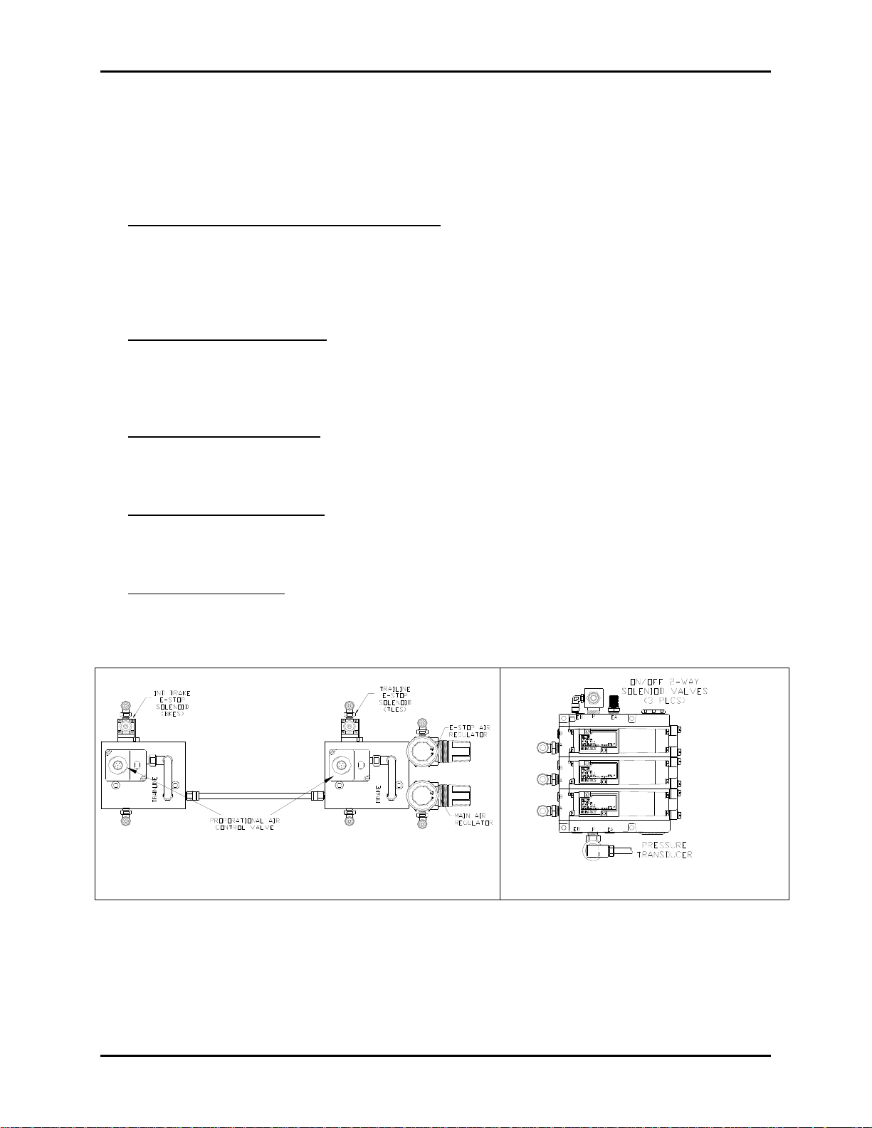
Pneumatic Components
The following pneumatic components comprise the pneumatic control and interface for the Train
Chief® II system and are included in the RCU, mounted on the specifically designed enclosure
back plate.
PROPORTIONAL VALVES AND MANIFOLD
Manifolds have been specifically designed to integrate the brake pneumatic components.
Referred to as the “proportional valve manifold”, one manifold integrates all components
used both normal and emergency brake control with the required regulators. Another
proportional valve manifold is used for normal and emergency trainline brakes, when
present.
PRESSURE REGULATORS
Supply air from the locomotive main reservoir is controlled using a 0-100-psi regulator, for
the pneumatic components used in the Train Chief® II system. A second stage 0-100-psi
regulator is used to further control the air used for emergency brake system. Both regulators
are located at the supply end of one of the proportional valve manifolds.
PRESSURE MONITORING
Main reservoir pressure is monitored by a dedicated transducer on the solenoid valve
manifold. Brakes and Trainline pressures are monitored by feedback from a dedicated
transducer fed from the actual application points on the locomotive.
EMERGENCY SOLENOIDS
The Brake Emergency Stop (BKES) solenoid is used to apply air for independent
emergency brake application. Additional a dedicated (TLES & TL DUMP) solenoid valves
are used to dump brake pipe air for emergency trainline brake application
SOLENOIDS VALVES
Solenoid valve(s) are provided (and integrated on a dedicated manifold) that are used to
control additional locomotive functions such as horn/bell, sanding, and uncoupling. Refer to
your system specific documentation to find which features are included on your system.
1<0$7,&6 1<0$7,&6
+251
5
%$ ,/
5
%(//
5
Figure 3-9: Typical Pneumatic Components
95-00-0-xxx Rev 000 3-11 Control Chief Corporation
Page 22

TRAIN CHIEF® II LRCS w/Lightweight OCU OWNER’S MANUAL
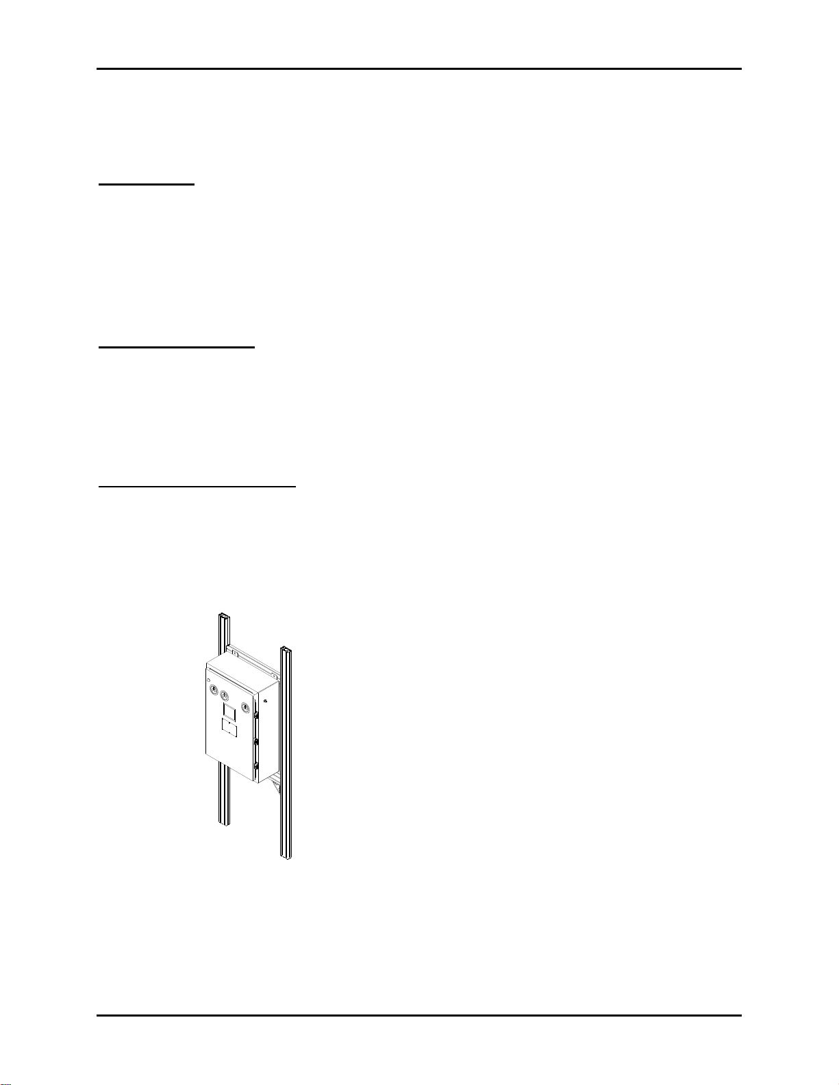
Receiver / Controller Unit Mounting
The RCU should be securely mounted inside the locomotive cab. The mounting location should
allow for reasonable access for both the electrical and pneumatic interfaces, but also be picked
to avoid interference with normal locomotive cab operations.
www.controlchief.com
Figure 3-10: RCU Physical Details
The best approach for mounting is to erect a simple rail system allowing for some adjustment
yet providing a good secure support. It is recommended that the mounting frame be erected
using metal rails strong enough to support the enclosure’s weight (~95 lbs.). As shown above.
The mounting tabs on the RCU enclosure are on 14” centers and are ~31” between top and
bottom. Be sure to leave adequate clearance below the unit to make all interface connections
and in front to allow for the access panel opening. The following figure provides a basic
mounting concept.
95-00-0-xxx Rev 000 3-12 Control Chief Corporation
Page 23

TRAIN CHIEF® II LRCS w/Lightweight OCU OWNER’S MANUAL
Figure 3-11
Locomotive Interface
Introduction
The connection of the RCU to the locomotive is achieved through both electrical and pneumatic
(air) interfaces. All locomotive interface connections are located on the bottom of the RCU. The
RCU manages all necessary connections for the specific locomotive functions. Once interfaced,
the RCU becomes an integral part of the locomotive system and utilizes the locomotive DC
power and main air reservoir supply. This enables the Train Chief® II system to support the full
functionality of the locomotive without any non-typical system configurations. Below is
discussion on some of the key elements of the locomotive interface. Refer to the system prints
for the detailed interfacing requirements for your specific locomotive.
Main Air Supply Shut-Off Valve and Filter Assembly
Located on the bottom of the RCU unit is the main air supply input for all pneumatic functions
controlled by the system. Ahead of the main air supply inlet (installed separately in the
locomotive cab) there must be a pneumatic shut-off valve and filter assembly (supplied in the
installation kit). The shut-off valve must be in the closed position (handle is at a right-angle to
the air-line) for manual and in the open position (handle in-line) for remote. The assembly also
includes two (2) filter housings: one is a particulate filter and the second is a coalescing unit.
These filters protect the pneumatic components in the system. These filters must be part of your
scheduled maintenance for the locomotive to insure optimum performance and maintain
warranty requirements.
Manual/Remote Transfer Switch
The manual/remote transfer switch is located on the right-hand side of the RCU. The function of
the switch is to transfer out critical manual (cab) locomotive functions when switching from
manual to remote, and to transfer out critical remote functions when switching from remote to
manual.
95-00-0-xxx Rev 000 3-13 Control Chief Corporation
Page 24

TRAIN CHIEF® II LRCS w/Lightweight OCU OWNER’S MANUAL
Manual/Remote Transfer Switch Selections and Functions
Function
Strobe
Manual
(CAB)
OUT
Remote Comments
IN
Strobe active ONLY in remote mode
Ignition Wire IN OUT Disables engine start when in remote
mode.
Throttle Switch IN OUT Disables manual throttle lever in remote
mode.
Head Light IN OUT Disables manual headlight switch in
remote mode.
Reverser IN OUT Disables reverser lever in remote mode.
Dedicated Locomotive Hook-Ups
Locomotive connections to the locomotive interface panel are accomplished through the bottom
of the panel via dedicated locomotive hookups. These hookups consist of connector sockets
based on system options to facilitate ease of installation.
¾ The pneumatic connections are located on the bottom left of the panel, and include quick
connect ports for main air, locomotive brake, train brake, and bail.
¾ The rectangular connector is for the general locomotive interface cable. The cable is 30-
conductor with a strain relief.
¾ The round connector(s) are for specific functions such as external E-Stop, strobe status
lights, and other optional features.
Refer to system prints, drawing E-9668-03-01 for more application specific details. Refer to
Figure 6-7 for detailed pneumatic interface diagram. Always refer to your system prints for
details specific to your system configuration.
95-00-0-xxx Rev 000 3-14 Control Chief Corporation
Page 25

TRAIN CHIEF® II LRCS w/Lightweight OCU OWNER’S MANUAL
The Installation Kit
Each system is shipped with an installation kit which includes various materials required for the
integration of the receiver / controller unit into the locomotive systems. The types of standard
materials provided included:
¾ Power Supply Input Filter and Surge Suppressor. The DC locomotive power is
conditioned by an input filter and surge suppressor. The function of this module is to
protect the Train Chief® II equipment from the electro-magnetic (EM) noise from the
locomotive power source to insure reliable operation of the remote control system.
¾ Surge Suppressors. Additional surge suppressor devices are provided to be installed
across all locomotive devices that are considered inductive loads (coils, contactors, etc.).
This is required to further control EM noise, created by the inductive devices, which may
interfere with the control electronics.
¾ Strobe Light. A strobe light, to be placed on the outside for the locomotive cab, is
included to provide visual indications of system status during remote operation.
¾ Locomotive Antenna System. The antenna system consists of a length of coaxial
cable, mounting bracket, ½ wave whip antenna, and the necessary parts and
instructions to install the antenna cable and antenna. The locomotive antenna kit
contains 20’ of cable (custom length versions are available) with a TNC female bulkhead
connector pre-installed (the other end is un-terminated to facilitate field installation),
antenna mounting brackets, TNC right angle plug, cable strain relief, and instructions.
The installation crimping tool kit (P/N 90-70-0-074) is required for proper antenna
connector installation.
¾ Cables. Pigtail cables are provided for the electrical interface between the receiver /
controller and the locomotive controls. Cables are provided with mating connectors at
one end for direct connection to the receiver / controller enclosure.
¾ Shock Mounts. Vibration shock mounts are provided for the mounting of the receiver /
controller in the locomotive cab. These are required to minimize the transfer of
locomotive vibration and prevent damage to the receiver / controller components.
¾ Pneumatic Interface Hardware. A variety of hardware is provided for the pneumatic
interface between the receiver / controller and the locomotive air systems. A water
separation/ filter assembly, shuttle valve, nylon tubing and various DOT-approved fittings
are typical in this kit.
¾ J1 Valve Kit. A J1 brake control valve can be provided, if trainline brakes are required.
95-00-0-xxx Rev 000 3-15 Control Chief Corporation
Page 26

TRAIN CHIEF® II LRCS w/Lightweight OCU OWNER’S MANUAL
General Installation Practices
WARNING: Before attempting to service any pneumatic components, ensure the air system has
been vented to atmosphere (zero pressure in air lines).
CAUTION: Contaminants in the air system can significantly reduce the component life and
performance of the remote control pneumatics. Therefore, to insure long component life and
optimum system performance it is essential to implement a preventive maintenance schedule
for the locomotive pneumatics system. This should include draining water from the main
reservoir tank and replacing filter cartridges. Failure to maintain main reservoir and/or filter may
void the warranty.
General Installation Practices
¾ Resolve any problems with the locomotive’s operation prior to attempting any remote
equipment installation or operation.
¾ All field wiring should be done by a qualified electrician. All electrical work and practices
must meet all federal, state, and local codes and standards.
¾ Route all wire and/or cable to avoid moving parts, mechanical vibration points, pinch
points, and high temperature surfaces. All wiring/cabling should be secured and must
meet all federal, state, local, and industry standards.
¾ Do not run power (high voltage > 50V) together with control (low voltage < 50V) wire or
cable.
¾ Electrical wiring running through the engine compartment should be contained in conduit
of proper rating for the environmental conditions present.
¾ All field plumbing should be done by a qualified technician. All plumbing work and
practices must meet all federal, state, local, and industry standards.
¾ Route all tubing and/or pipe to avoid moving parts, mechanical vibration points, pinch
points, and high temperature surfaces. All tubing/piping should be secured and must
meet all federal, state, local, and industry standards
¾ All plastic plumbing components must be DOT Approved.
¾ All equipment must be shock mounted in an appropriate manner to withstand all normal
operational conditions.
¾ Always read and follow all instructions provided with specific components in the field
installation parts kit.
¾ System specific requirements are included in the system print package. Please review
before beginning the installation. If you have any questions please contact Control Chief
Application Engineering department.
95-00-0-xxx Rev 000 3-16 Control Chief Corporation
Page 27

TRAIN CHIEF® II LRCS w/Lightweight OCU OWNER’S MANUAL
Specific Installation Requirements
¾ During the installation you may have to mark-up prints. Upon completion of the
installation forward these prints to Control Chief Corporation Application Engineering so
the mark-ups can be incorporated in our drawings and an updated copy provided.
¾ Locomotive Antenna Installation. Always consider the following general guidelines:
o The locomotive antenna should be mounted on the cab roof in a vertical position
using the magnet mount hardware provided in the accessories kit.
o The locomotive antenna should have a minimum clearance of 36” between it and
any other obstruction mounted on the cab roof. If the minimum clearance is not
possible, then the installation must be tested to determine if the proximity of
obstructions impact system performance.
o Do not locate antenna in close proximity of any existing UHF/VHF (voice)
antenna(s).
o Pick a location (typically as high as possible) that provides a clear path between
the antenna and the likely transmitter location(s).
o Ensure the antenna cable routing to the receiver / controller unit is such that the
¾ Wiring and Grounding. To avoid EM interference and ensure control system reliability,
specific grounding and shielding practices are required. The following list provides the
minimum guidelines and practices required:
antenna cable will not be cut or damaged by any moving parts.
.
o All coaxial and/or shielded cables are to be grounded at ONE end only. The
cable shield must be grounded at the end closest to the transmitted voltage
source (i.e. power supply end for transducers not at the transducer itself).
o All required grounding must be to a common ground plane, which in turn has a
single ground (bonding) connection to earth ground.
o Bonding of the locomotive ground connection must be done using a copper braid
¾ Remote E-Stop Installation. All externally mounted remote E-Stop enclosures must be
NEMA 4 rated. All remote E-Stop enclosures provided are NEMA 4 or better. Any field
modifications must be done in such a way as to maintain this rating. All enclosure
penetration must be appropriately sealed to prevent environmental leakage. “Dowty”
washer should be used on all cable connectors.
¾ Suppressors Installation Requirements. Another very important requirement, to
minimize EMI, is the installation of suppressors across ALL inductive loads (solenoid
valve and relay/contactor coils). Control Chief will provide all the appropriate
suppressors based on your locomotive design. It is very important to identify all
inductive loads present and to have the appropriate suppressors installed prior to
remote control operation.
(provided). DO NOT SUBSITUTE.
95-00-0-xxx Rev 000 3-17 Control Chief Corporation
Page 28

TRAIN CHIEF® II LRCS w/Lightweight OCU OWNER’S MANUAL
4 START UP AND OPERATING PROCEDURES
Locomotive Stops
The locomotive remote control system can automatically initiate either of two (2) types of
locomotive stops, depending on the specific situation. The two locomotive stops are defined
below and are referenced in subsequent operational descriptions.
Full-Application Locomotive Stop - The full-application locomotive stop is automatically
initiated in certain situations that are deemed non-emergency. This type of locomotive stop
requires a reset of the OCU to resume normal operation. The full-application locomotive stop
automatically initiates the following actions;
¾ full application of independent (locomotive) brakes
¾ full application of trainline brakes (when present)
¾ locomotive throttle to idle
¾ disengagement of generator field
Emergency Locomotive Stop - The emergency locomotive stop is automatically initiated in
certain situations (including the E-Stop command) that are deemed an emergency. This type of
locomotive stop will require specific intervention in order to resume normal operation. The
emergency locomotive stop automatically initiates the following actions;
¾ emergency applications of independent (locomotive) brakes
¾ emergency application of trainline brakes (when present)
¾ locomotive throttle to idle
¾ disengagement of generator field
¾ After any emergency locomotive stop, the operator may not be able to restart the system
from the remote OCU (or remote control station) because the locomotive will be in a
Power Cut-off Switch (PCS) fault condition. To recover from this condition the operator
may need to go to the locomotive cab to reset the PCS fault. PCS fault reset procedures
will be dependant and specific to the locomotive.
Locomotive PCS Fault – The locomotive PCS fault is a latching condition that may occur on
the locomotive that will prevent locomotive operation. This fault may occur whenever there is an
emergency application of trainline brakes, based on a locomotive pressure switch that monitors
the trainline brake air pressure.
¾ The emergency application of trainline brakes will occur whenever the remote control
system commands an emergency locomotive stop, forcing the PCS fault condition. This
will happen whenever;
o an E-Stop button is pressed
o the OCU tilt (man down) feature is triggered
¾ Depending on the locomotive and whether it is in manual control or remote
control mode, the procedure to reset a PCS fault may be different. It is the
responsibility of the operator to understand the specific locomotive PCS fault
reset procedures required.
95-00-0-xxx Rev 000 4-1 Control Chief Corporation
Page 29

TRAIN CHIEF® II LRCS w/Lightweight OCU OWNER’S MANUAL
Brake Monitoring
In order to monitor brake related component failure, the system monitors the independent brake
pressure. If the air pressure does not exceed at least 30 PSI within 3 seconds of a commanded
FULL INDEPENDENT brake, then an EMERGENCY STOP condition is activated. To reset this
condition, cycle power to the receiver cabinet only. When a brake monitor fault occurs, the Low
Main Reservoir indicator light located on the top front of the receiver cabinet will flash at a rate
of ON ½ second and OFF ½ second. This fault will force you to cycle power to the system to
clear the fault.
Setup for Remote Control Operation
Initial Locomotive Setup
It is essential for safe and efficient remote control operations that the locomotive is in proper
working order in manual mode. Verify that all brake pipe hoses are connected and cutout valves
are OPEN.
Verify the transfer switch on RCU is in the MANUAL position. This switch is located on the right
hand side of the unit.
Verify the locomotive throttle is in idle and the reverser is centered.
Start engine. Let engine idle in manual until main reservoir air pressure reaches 105-psi or
greater.
Verify the automatic brake valve handle is in the HANDLE OFF position. Wait for brake pipe
pressure and equalizing reservoir pressure to equal zero. Both the brake pipe pressure and
equalizing reservoir pressure must be equal before transferring to remote. Failure to do so will
result in a locomotive PCS fault.
CAUTION: Failure to position the automatic brake valve handle in the HANDLE OFF
position could result in a brake release condition when the remote control system is
switched back to manual mode.
Place the transfer switch on the right side of the receiver / controller unit in the REMOTE
position.
Locate the isolation valve on the filter assembly air supply and make sure that the valve is in the
ON/OPEN (UP) position.
OCU Setup
¾ All switches and levers should be in their OFF positions.
¾ Set INDEPENDENT BRAKE Selector to fifth position for FULL service brake application.
¾ Check AUTO BRAKE toggle in center position.
¾ Place HORN/BELL switch in OFF position (toward operator).
¾ Place the Reverser switch in NEUTRAL position.
¾ Throttle selector in HALT position.
¾ E-Stop pulled out.
¾ OCU not tilted.
Note: The operator should be wearing the break-away vest by this time. The unit should be
secured to the break-away vest. The operator can adjust the equipment straps so the unit fits on
the chest at a comfortable position. The break-away vest also has a waist belt to accommodate
a comfortable fit using one of three belt sizes.
95-00-0-xxx Rev 000 4-2 Control Chief Corporation
Page 30

TRAIN CHIEF® II LRCS w/Lightweight OCU OWNER’S MANUAL
¾ Turn on the Lightweight OCU by pressing the Power-On pushbutton at the lower right
hand corner of the unit (see Figure 3-3). At power-on the OCU will perform a Power-OnSelf-Test (POST). When POST has completed successfully the unit is ready to be
assigned to a Train Chief® II equipped locomotive.
A successful POST is indicated by the flashing OCU indicators and display message (“OCU >
LOCO ALIGN IR”).
If an error is detected during the POST an error message will be displayed and the unit will be
disabled. See the troubleshooting section for further details.
OCU Assignment Procedure – Register OCU with Locomotive
How to Register the OCU for single man operation.
At Receiver Power up: IR Indicating LED illuminated (RED)
¾ Power up Transmitter and wait for POST. Follow prompts on Transmitter display.
¾ Align Transmitter IR port with Receiver IR Window on Enclosure front (Fig 6.1).
¾ Once the IR Process is complete the Transmitter will BEEP. Press the “RESET”
button to initiated RF communication. The IR Indication LED will go off.
At Transmitter Only Power up (Receiver already ON) LED Not illuminated:
¾ Power up Transmitter and wait for POST. Follow prompts on Transmitter display.
¾ Push & hold (for 3 seconds till LED comes on) the IR REQUEST pushbutton.
¾ Align Transmitter IR port with Receiver IR Window on Enclosure front (Fig 6.1)
¾ Once the IR Process is complete a Transmitter will BEEP. Pre4ss the “RESET”
button to initiated RF communication. The IR Indication LED will go off.
OCU Configuration Incompatibility Messages and Definitions:
Display Message Definition Action
Model/Owner is not compatible.
CONFIG
OCU Models can not be
interchanged with RCUs or with
different equipment owners.
RADIO
OCU and RCU Radio model types
incompatible
BAND Radio out of Band
Obtain the unit(s) configured for the RCU and
register. Refer to the configuration label next
to the IR Port on the RCU. (For MU&Go
RCUs this label is inside the enclosure door.)
Obtain the unit(s) configured for the RCU and
register. Refer to the configuration label next
to the IR Port on the RCU. (For MU&Go
RCUs this label is inside the enclosure door.)
Obtain the unit(s) configured for the RCU and
register. Refer to the configuration label next
to the IR Port on the RCU. (For MU&Go
RCUs this label is inside the enclosure door.)
95-00-0-xxx Rev 000 4-3 Control Chief Corporation
Page 31

TRAIN CHIEF® II LRCS w/Lightweight OCU OWNER’S MANUAL
Transfer to Remote Mode and Resetting Locomotive PCS Fault.
To activate the communication link from OCU to locomotive, move the horn toggle to HORN.
The locomotive should respond by sounding the locomotive horn. Return the toggle to OFF.
Note: If the locomotive bell begins to sound it is an indication that the main reservoir is
below 75-psi. This could indicate that the isolation valve is in the wrong position.
Recheck the valve and continue with the start up procedure. If the valve is in the
correct position then recharge the main air reservoir. This is accomplished by
placing the directional switch on the OCU in NEUTRAL and increase engine
throttle. Throttle will automatically reduce once the 105-psi main reservoir
pressure in reached. Now activate the RESET button.
Release the trainline brake by pressing the AUTO BRAKE toggle switch to the release position.
The command is accepted when the keypad AUTO BRAKE REL indicator turns ON.
Reset the locomotive PCS fault, if required.
¾ Older systems did not provide an indication of when or if the PCS Fault was activated. If
the system didn’t respond the operator would go to the locomotive and manually reset
the fault.
¾ On newer systems the locomotive brake status lights are disabled when a PCS Fault is
activated. To recover from PCS Fault the operator simply sounds the horn. When the
fault is cleared the brake status lights should turn on.
¾ The OCU with two-way communication link will be able to show a PCS Fault message
on the OCU display.
Ensure the Independent (locomotive) brake valve handle is in the FULL INDEPENDENT
RELEASE position.
WARNING:
The remote control system cannot control independent brakes until the
independent brake valve handle is in the FULL INDEPENDENT RELEASE
position.
Ensure that the manual headlight switches are OFF, the dimmer switch is set to DIM, the
generator field is ON, and the isolation switch is in the RUN position.
If Trainline Braking option is installed:
¾ For systems utilizing the J1 relay valve for trainline, place the trainline isolation valve to
the REMOTE position.
¾ For systems utilizing the 26L brake cover for trainline, place the trainline dump valve to
the OPEN or REMOTE position.
The remote control system now has primary control of the locomotive.
95-00-0-xxx Rev 000 4-4 Control Chief Corporation
Page 32

TRAIN CHIEF® II LRCS w/Lightweight OCU OWNER’S MANUAL
Air Brakes and Safety Features Test
According to the FRA Safety Advisory 2001-01 it is recommended that the air brake and safety
function of the OCU be tested at the beginning of any remote control activity. The following
summary is provided in support of that practice.
Locomotive Brake Test. Perform all required standard locomotive and trainline brake tests
using the OCU to ensure all remote braking functionality.
E-Stop Test. Perform an E-Stop from the OCU to verify remote activation of the emergency
locomotive stop. Also test all other locomotive mounted E-Stop push buttons associated with
the remote control system.
Tilt Test. To test the Tilt feature of the OCU, tilt the OCU more than 45-degress. The OCU is
operating properly when:
¾ A continuous tone begins within approximately three (3) seconds
¾ Then a Tilt Time Out occurs after approximately two (2) seconds of tone
¾ The RCU responds by commanding an Emergency Locomotive Stop
To recover from a Tilt Time Out Fault, return the OCU to normal operation position.
Local Man-Down Alarm Test. To test the local man down alarm, maintain the OCU in a tilted
position while in an active tilt alarm condition. After a period of not greater than 90-seconds and
not less than 60-seconds the locomotive horn shall sound at an alternating rate of one second.
The locomotive horn will continue to sound the man down alarm until the system is reset.
Remote Man-Down Alarm Test (if present). If your system is equipped with the optional
remote man down feature, the remote man down alarm is triggered when the local man down
alarm is activated. Refer to the system configuration documents for your specific operational
detail.
Alert Test
To test the Alert feature of the OCU
¾ Place the Reverser selector in Neutral
¾ Place Independent Brake to Full position
¾ Set Auto Brake to RELEASE (or some application to hold the train in position)
¾ Set Throttle selector out of HALT
¾ Wait for approximately 50 seconds
The OCU is operating properly when
¾ A fast rate pulse tone begins after approximately 50 seconds
¾ Then after approximately 10 seconds an Alert Time OUT occurs
¾ The RCU responds by commanding Full Service Locomotive and Automatic Brake
To recover from an Alert Time Out, return the OCU Throttle selector to HALT position.
Application.
Initial start-up and safety checks are completed.
The system is ready for operation.
95-00-0-xxx Rev 000 4-5 Control Chief Corporation
Page 33

TRAIN CHIEF® II LRCS w/Lightweight OCU OWNER’S MANUAL
Normal Operation
Train Chief® II with Lightweight OCU Brake/Throttle Control Configuration
As an operator, you can control movement with an OCU in several different ways. This section
covers:
¾ Setting movement direction
¾ Starting (Train Handling)
¾ Alert Operation
¾ Stopping and changing directions
¾ Emergency brake applications
¾ Winter operation
¾ Transferring operator control (Selective Dual Control option)
Setting Movement direction
Set direction of movement using the reverser selector.
¾ Forward is the direction the short hood in the Train Chief® II equipped locomotive faces.
¾ Train Chief® II does not allow you to change the direction of movement until the
locomotive brakes are fully applied.
Operating procedure:
¾ Throttle selector to HALT.
¾ Wait for locomotive to come to a complete stop.
¾ Move Reverser to a desired direction selection.
o If a direction change is made while the locomotive brakes are released, the OCU will
declare a Reverser Change Alarm and the controller will command the throttle to
idle, apply full locomotive brakes, and disengage generator field.
o To recover from the Reverser Change Alarm place the Throttle selector to HALT
position.
Caution
This Train Chief® II configuration employs a Manual Throttle & Brake
Control enabling the operator to achieve similar movement control as if
the operator where at the locomotive control stand. This type of operation
from a distance requires the operator to be very conservative about
judging speed and stopping distances relative to being in or near the
locomotive cab.
95-00-0-xxx Rev 000 4-6 Control Chief Corporation
Page 34

TRAIN CHIEF® II LRCS w/Lightweight OCU OWNER’S MANUAL
Starting (Train Handling)
¾ Set Movement Direction (FWD or REV)
¾ RELEASE Automatic Brakes by pulling the toggle switch for 1-2 seconds (if equipped).
¾ RELEASE the locomotive brakes:
o Move the Independent Brake selector to RELEASE (rotation toward operator) as
shown by all indicators off.
¾ Press RESET (to reset brakes)
o Throttle selector must be moved from the HALT position within 3 seconds of pressing
the RESET.
¾ Advance the throttle selector to the appropriate throttle position to generate the required
power to slowly accelerate the train.
¾ Use the Automatic or Independent Brake selectors to slow or stop the locomotive.
o Locomotive brakes can also be applied by moving the throttle selector to HALT.
¾ To resume movement (without reverser change):
o Press RESET
o Within two seconds the Throttle selector must be moved out of HALT position or else
the selection will be ignored.
● If ignored, place Throttle to HALT and repeat from RESET.
Note:
Radio Communications – Typically the OCU transmits four messages per second
to the locomotive equipment. If the locomotive does not receive a valid message
within a set timeout period (typ 1.25 sec) a Full Service Brake Application will
occur. During the timeout period the last valid command will prevail.
Alert Operation
The operator alert function is activated when the Throttle selector is moved out of the HALT
position (regardless of the Reverser selection).
If there has not been any function or command switch activity (i.e. periodic pressing of the
RESET switch) for more than 60 seconds then Train Chief® II will automatically initiate the FullApplication Locomotive Stop command.
o The Alert Timeout warning will cause a fast pulse tone after 50 seconds of command
switch inactivity to alert the operator of an impending Full-Application Locomotive
Stop.
o If the operator responds to the Alert Warning by pressing ANY button within 10
seconds the alarm is cleared.
¾ To recover from an Alert Timeout, return the OCU Throttle selector to HALT position.
¾ The specific time setting for the alert feature may be different, based on specific user
request. Refer to site operating rules.
95-00-0-xxx Rev 000 4-7 Control Chief Corporation
Page 35

TRAIN CHIEF® II LRCS w/Lightweight OCU OWNER’S MANUAL
Stopping and Changing Directions
To stop the train manually using the Independent Brake selector:
¾ Rotate the Throttle selector to IDLE
¾ Rotate the Independent brake selector to apply the required braking power to bring the
train to a manually controlled stop.
¾ Once the train is stopped a new direction can be selected using the reverser toggle
switch.
To stop the train automatically using HALT:
¾ Turn the Throttle selector to HALT and wait three (3) seconds for the HALT timeout
indicated by a single OCU beep. The RCU will automatically apply a controlled
application of independent brake.
¾ To recover from a Full Brake application
o set Independent Brake selector to RELEASE,
o press RESET and
within three (3) seconds move the Throttle selector out of HALT.
Note: This is a more aggressive controlled stop where the Train Chief® II system applies a
ramped application of independent brake until a full-application locomotive stop is achieved.
Trainline Brake Operation (when equipped)
When the Train Chief® II system is equipped with optional trainline brake control the Automatic
Brake selector on the OCU will be used to apply and release train brakes.
¾ The Automatic Brake release is selected when the toggle is pulled toward the operator
o The receiver / controller commands full air pressure to the brake pipe which places
the train brakes in a fully released state.
¾ The trainline brakes are progressively applied each time the trainline brake switch is
momentarily pressed away from the operator.
o When the switch returns to center the last commanded pressure is maintained.
o If desired, Bail off independent brakes by pressing the Bail function switch.
¾ When the Automatic Brake selector is pressed for apply for more than two (2) seconds
full service trainline brakes are commanded.
Tilt
When communications are active and the OCU is tilted, the audible indicator will sound a
continuous beep (critical warning) for about 2 seconds before commanding an emergency
locomotive stop.
Once the emergency locomotive stop command is sent, the alarm no longer sounds
continuously, but will sound once every 3 seconds to indicate that the locomotive emergency
stop command continues to be sent.
¾ This condition continues as long as the OCU remains tilted.
The tilt condition is cleared when the OCU is returned to its upright position, or when power is
turned off, or when the battery becomes fully discharged.
¾ Once cleared, the tilt alarm will stop.
95-00-0-xxx Rev 000 4-8 Control Chief Corporation
Page 36

TRAIN CHIEF® II LRCS w/Lightweight OCU OWNER’S MANUAL
Tilt Extend
The tilt extend is provided to facilitate operator tasks requiring two hands.
To extend the tilt timeout the independent brakes must be applied.
¾ Set the Throttle selector to HALT.
¾ Press the F1 push button on the keypad until the OCU acknowledges the request with a
beep then release F1.
¾ The operator has 60 seconds to perform tasks while tilting the OCU.
¾ The Tilt Extend is canceled when the operator moves the Independent Brake from the
FULL application selection or moves the Throttle Selector out of HALT.
Man Down Alarm
When the tilt function has been active for more than 1 minute the locomotive horn will begin to
cycle on and off or sound continuously depending on your site operating rules.
The alarm will continue to be active until the receiver/controller is reset.
If the OCU is returned to its normal operating position before the man down timer expires the
alarm will be cleared.
To recover from Man Down Alarm: recycle power on the RCU and OCU. Then perform initial
setup procedures. See Chapter 4.
Emergency brake Applications
In emergency situations, emergency brakes are activated by pushing in the RED Mushroom
push button next to the reverser switch. This action causes the OCU to send an operator
Emergency Stop command. The controller will respond by commanding an Emergency
Locomotive Stop.
To recover from an operator Emergency Stop, pull-out the Red E-stop mushroom push button,
Throttle selector to HALT, Independent Brake to FULL.
Train Chief® II will also apply emergency brakes when a serious fault occurs in the system.
In either case, Train Chief® II quickly opens the Brake pipe to apply emergency brakes to both
locomotive brakes and trainline.
¾ When operating with dual OCU’s in Selective Dual Control operation, the locomotive will
accept an Emergency Stop command from either OCU at any time.
Note: An emergency brake application completely drains (dumps) the brake pipe on all
cars. Recharging times will vary greatly depending on the number of cars connected
and weather conditions.
Operating under winter conditions
During winter conditions, brake components may get covered with snow or ice and braking
power may be reduced. Therefore, during these types of conditions, make regular brake
applications to keep the braking components working properly.
¾ With the locomotive moving at a speed of no greater than 4 mph (6 ft/sec), apply a small
amount of brakes by moving the Independent Brake selector to Low position. This
allows friction to melt away snow and ice on the shoes and wheels.
95-00-0-xxx Rev 000 4-9 Control Chief Corporation
Page 37

TRAIN CHIEF® II LRCS w/Lightweight OCU OWNER’S MANUAL
Transferring from Remote to Manual
¾ Go to the locomotive and place the independent brake handle into the FULL APPLY
position and the automatic brake handle to the EMERGENCY position.
¾ Place the transfer switch on the receiver / controller unit in the MANUAL position.
¾ Place the air valve that feeds the receiver / controller unit in the OFF/MANUAL position.
¾ Place the brake pipe isolation valve in the MANUAL position.
¾ Recover from the locomotive PCS fault condition using the normal procedure.
Move the auto automatic brake handle to the RELEASE position.
¾
If Trainline Braking option is installed:
¾
o For systems utilizing the J1 relay valve for trainline, place the trainline isolation
Move the independent brake handle to the SET position.
¾
¾ Turn off and secure the OCU to provide protection against unauthorized operation.
¾ Resume normal operations.
valve to the MANUAL position.
o For systems utilizing the 26L brake cover for trainline, place the trainline dump
valve to the CLOSED or MANUAL position.
95-00-0-xxx Rev 000 4-10 Control Chief Corporation
Page 38

TRAIN CHIEF® II LRCS w/Lightweight OCU OWNER’S MANUAL
5 OPTIONS
The following optional features are included in your Train Chief® II system.
Special Features Supplied
Independent Brake Bail Option
The locomotive independent brakes are applied and released automatically by the locomotive
brake distribution valve (if equipped), in a manner similar to that which is achieved when braking
is controlled manually from the locomotive brake stand. The bail function allows the
independent brake to be released while the trainline brake continues to be applied.
Locomotive Mounted E-Stops
In addition to the E-Stop button located on the OCU, up to four (4) additional hardwired E-Stop
buttons can be provided on the locomotive. All E-Stop buttons are wired in series such that
activation of any one will command the E-Stop reaction. These additional E-Stop buttons must
be located on the locomotive, since they are hard wired into the receiver / controller unit.
Wheel-slip Alarm Option
When present, the existing locomotive’s wheel slip monitoring device can be monitored by the
locomotive remote control system. When wheel slip is detected by the LRCS the throttle can be
automatically reduced or maintained steady depending on customer’s decision at time of
purchase. Throttle advance is also restricted while there is wheel slip being detected.
Sanding Options
Direct electric control has been provided to initiate the locomotive sanding function. Typically
the dual function RESET / SAND
OCU for this function. Sanding is always in the direction of travel.
pushbutton as described in Chapter 3 is employed on the
95-00-0-xxx Rev 000 5-1 Control Chief Corporation
Page 39

TRAIN CHIEF® II LRCS w/Lightweight OCU OWNER’S MANUAL
OCU Two-Way Operational Messages
OCU Status Messages (Solicited)
Item OCU Message Description Comments
1 BATT LVL OCU Battery Level
E ░ ░ ░ ░ ░ ░ F
2
3 BRK PIPE Brake Pipe Pressure (PSI)
4 BRKCLDNR Brake Cylinder Pressure (PSI)
MAIN RES
XXX PSI
XX PSI
XX PSI
Main Reservoir Pressure (PSI)
OCU Operational Warning and Alarm Messages (Unsolicited)
Item OCU Message RCU Operational Action Description Comments
1
2
3
4
5
6
7 WHL SLIP Throttle hold Wheel Slip
Low MR
(Low MR Pressure)
MAN DOWN
OCU-A
OCU
E-STOP
RCU
E-STOP
REVERSER
(Illegal Reverser
Change)
TILT
(Tilt Timeout)
Full Locomotive Stop MR < 105 PSI
Emergency Stop
Emergency Stop Operator requests an emergency
Emergency Stop
Full Locomotive Stop
Emergency Stop Tilt Timeout
External E-Stop on Locomotive
activated (pushed IN)
Direction change while in
movement or not in STOP
95-00-0-xxx Rev 000 5-2 Control Chief Corporation
Page 40

TRAIN CHIEF® II LRCS w/Lightweight OCU OWNER’S MANUAL
6 DETAILED EQUIPMENT DESCRIPTIONS
Lightweight OCU Features
The Train Chief® II LRCS receiver/controller unit and Lightweight OCU operate with the
Advanced Universal Transmitter system that allows the assignment of a given OCU to a specific
locomotive. The OCU assignment system will allow any OCU to be assigned to any locomotive,
with identical controls and configuration. This system provides an extensive degree of flexibility
for any given equipment set. The Advanced Universal Transmitter incorporates an additional
level of communication security to ensure that only authorized and authenticated (properly
assigned) OCUs will work with locomotives within the designated group.
www.controlchief.com
IR Port
Figure 6-1
Operational Description
¾ Each receiver / controller unit (located in the locomotive) has a unique hard coded
identification code and (within a group of locomotives) a discrete radio frequency.
¾ Each OCU has a unique identification code and is radio frequency agile to operate on
any of the locomotive group’s frequencies.
¾ The OCU and locomotive are field configured to operate together by using the OCU
assignment procedure.
¾ OCU assignment is accomplished through a duplex infra-red link that exchanges
information (data) between the receiver / controller unit and the OCU. The receiver /
controller locomotive’s ID code and operating frequency and the OCU’s ID code are
exchanged during this process. Once completed, the specific OCU is assigned to that
specific locomotive and RF communication and remote control operations can
commence over the radio link.
¾ Since both the locomotive and OCU have exchanged their unique identities, the OCU
can only communicate with its assigned locomotive. If an attempt is made to assign the
OCU to another locomotive, the assignment process will re-write the locomotive’s data in
the OCU memory, disabling RF communication to the previous locomotive.
¾ Since the locomotive receiver and OCU trade their unique identities they are then paired
to the exclusion of other nearby OCU s and receivers until power is removed or a reassignment occurs.
95-00-0-xxx Rev 000 6-1 Control Chief Corporation
Page 41

TRAIN CHIEF® II LRCS w/Lightweight OCU OWNER’S MANUAL
¾ Anytime the locomotive is returned to manual operation or the OCU power is switched
OFF, the stored data will be lost requiring the assignment process to be repeated. The
OCU will not lose its assignment data during a “hot battery swap” if the swap is
accomplished promptly, within approximately 1 minute.
IR Registration Process:
At Receiver Power up: IR Indicating LED illuminated (RED)
¾ Power up Transmitter and wait for POST. Follow prompts on Transmitter display.
¾ Align Transmitter IR port with Receiver IR Window on Enclosure front (Fig 6.1).
¾ Once the IR Process is complete the Transmitter will BEEP. Press the “RESET”
button to initiated RF communication. The IR Indication LED will go off.
At Transmitter Only Power up (Receiver already ON) LED Not illuminated:
¾ Power up Transmitter and wait for POST. Follow prompts on Transmitter display.
¾ Push & hold (for 3 seconds till LED comes on) the IR REQUEST pushbutton.
¾ Align Transmitter IR port with Receiver IR Window on Enclosure front (Fig 6.1)
¾ Once the IR Process is complete a Transmitter will BEEP. Pre4ss the “RESET”
button to initiated RF communication. The IR Indication LED will go off.
OCU Controls
13
14
3
Figure 6-2: OCU-BTIND Main Controls
1. Throttle Selector:
Ten detents for HALT, IDLE and eight (8) increments of throttle position. The throttle selection
is indicated by LEDs on the display.
Throttle select positions:
• Halt: commands the throttle to idle, removes generator field and applies
independent brakes in a controlled manner.
12
15
11
10
4
5
95-00-0-xxx Rev 000 6-2 Control Chief Corporation
Page 42

TRAIN CHIEF® II LRCS w/Lightweight OCU OWNER’S MANUAL
• Idle: commands the throttle to idle, removes generator field, but does not apply
brakes.
• The remaining settings 1 – 8 command the same throttle settings as the control
cab console settings of the same number.
2. Power Switch:
Recessed Push-ON Push-OFF switch controls power to the OCU. Pressing the button applies
power to the unit from the battery pack and power bridge. Pressing the button again removes
power to the unit. Depending on the charge state of the power bridge, the OCU may initiate its
POST (Power-On-Self-Test) without an installed battery, but the unit will inhibit further operation
until a battery pack is installed.
3. Pitch:
This button is used to transfer LRC command to another OCU for “Pitch & Catch” operations
when Selective Dual Control is operational. Refer to page 4-2 in this manual describing the
Selective Dual Control feature.
4. Horn / Bell Switch:
This is a 3-positon switch. It is latched at the rear (OFF) position and at the center (BELL)
position. The forward (HORN) position is spring loaded to return to BELL position when
released. Return the switch to the OFF position to silence the Bell.
Specific to BELL function:
Whenever locomotive independent brakes are fully applied and
the Throttle selector is moved from Halt to some movement position, Train Chief® II sounds
the bell for 5 to 15 seconds. (Bell ringing durations are based on customer requirements for
their operation.)
Specific to HORN function:
The Horn function is used to acknowledge or accept a “Pitch”
from a transferring OCU.
5. Headlight / Extra Tilt Extend button: (options)
When the Headlight option is installed this button can toggle the state of the locomotive
headlights between DIM (default setting) and BRIGHT, or between ON and OFF. An indicator
on the OCU keypad will indicate the state of the control. See Chapter 5 for full explanation.
When the Tilt Extend option is installed this button will perform the same function as the F1
button on the keypad.
6. Audible Alarm:
The audible alarm provides a means with which to audibly prompt the operator of operational
status thereby enabling the operator to maintain visual attention on the task at hand. The
following table provides a description of the various alarm functions and their audible
indications.
Function Sound Pattern
OCU Assignment Success 1 Beep
OCU Assignment Failure 2 Beeps
Alert Time-Out Warning Fast Beep rate for 10 seconds
Tilt Warning Constant tone for up to 3 seconds
Tilt Time Extend Acknowledged 1 Beep
OCU Detected Error Condition 3 Beeps
Low Battery “Warning” Double beep every 30 seconds (up to 15 minutes.)
Low Battery “Shutdown Warning” Double beep every 15 seconds (up to 5 minutes.)
Low Battery “Shutdown” 1 beep every 4 seconds – replace battery pack to recover.
95-00-0-xxx Rev 000 6-3 Control Chief Corporation
Page 43

TRAIN CHIEF® II LRCS w/Lightweight OCU OWNER’S MANUAL
7. Independent Brake Selector:
Six position selector allows you to apply independent locomotive brakes to achieve the desired
stopping power.
Selectable positions are:
• Release (0 psi): this is the normal operating position when operating in power
mode (Throttle positions 1-8). (Note RELEASE selection is indicated when all
Independent Brake LEDs are off.)
• B1: Applies 1/5 of the available independent brake pressure to the brake
cylinders. Throttle selections T1 to T8 are allowed.
• B2: Applies 2/5 of the available independent brake pressure to the brake
cylinders. Throttle selections T1 to T8 are allowed.
• B3: Applies 3/5 of the available independent brake pressure to the brake
cylinders. Throttle selections T1 to T8 are allowed.
• B4: Applies 4/5 of the available independent brake pressure to the brake
cylinders. When brake pressure reaches 20 PSI the throttle is limited to T4. See
note.
• FULL: Applies total available independent brake pressure to the brake cylinders.
When brake pressure reaches 20 PSI the throttle is limited to T4. See note.
NOTE: The parameters used to establish thresholds for limiting throttle for a given brake
pressure can be adjusted per owners’ operating rules and requirements.
8. Internal Tilt Switch:
Located behind the keypad is an internal tilt switch or sensing device. If the transmitter is tilted
in any axis beyond 60-degress of upright for more than the preprogrammed tilt timeout setting
(typically 5 seconds), a tilt alarm becomes active. The tilt alarm feature is described in more
detail in Chapter 4.
9. Reset (optionally Reset/Bail):
The pushbutton located at the top left hand corner of the OCU provides an Alert reset function:
1. It resets the Alert warning. See page 4-9.
2. It instructs the RCU to allow a brake release when the operator moves the Throttle selector
out of the HALT position.
CAUTION:
Unless the Reset pushbutton is released, an Alert Timeout error will occur
and the system will command a Full-Application Locomotive Stop.
This pushbutton can also perform the optional dual function of RESET / BAIL. Alert reset
functions are same as above. The BAIL function allows the independent brakes to be released
while the train brake remains applied. For the BAIL function, when the button is pressed for
longer than 2 seconds the controller will bail off independent brake.
95-00-0-xxx Rev 000 6-4 Control Chief Corporation
Page 44

TRAIN CHIEF® II LRCS w/Lightweight OCU OWNER’S MANUAL
10. Automatic Brake Selector:
This 3-position spring centered switch allows you to release or apply train brakes by reducing
brake pipe by the following pressures:
• Release 0-psi reduction
• Minimum 6-8 psi reduction
• Light 10 psi reduction
• Medium 18 psi reduction
• Full 26 psi reduction
• The Charge position is used to charge the air brake system.
The center switch position (LAP) maintains the last brake setting.
Each time the switch is pressed (must be held for 0.5 sec); the train brakes are incremented to
the next higher/lower setting.
On the first application of Auto Brake the locomotive brake portion of the train brake application
is automatically bailed off.
Whenever the switch is pulled (must be held for 2 sec), the train brakes immediately revert back
to Release position.
11. Emergency Stop Push Button:
This control is a push-pull mushroom switch. Push-in to activate an operator commanded
Emergency Locomotive Stop. For normal operations the EMERGENCY mushroom must be
pulled-out.
Note: Emergency stop develops high brake cylinder pressures which increases the chance of
locking the locomotive wheels. Therefore, only use the EMERGENCY mushroom switch when
absolutely necessary.
12. IR Port:
Used to link OCU to Train Chief® II locomotive controller. Align with IR Port on the RCU when
registering a Lightweight OCU-BTIND with RCU.
This is the access window for IR (infrared) communication from the OCU when registering with
a RCU. Simply align the OCU IR port with the IR port per the instructions in Chapter 4.
13. Reverser Toggle:
This 3-position switch selects locomotive movement direction as Forward, Reverse, or Neutral.
14. Reset / Sand Button:
Pressing Reset for more than 2-seconds will activate Sanding by selected direction.
The Reset/Sand push button is located at the top right hand corner of the OCU.
1. It activates the sanders in the direction of movement when held for longer than 2 seconds.
2. It resets the Alert warning. See page 4-9.
3. It instructs the RCU to allow a brake release when the operator moves the Throttle selector
out of the HALT position.
CAUTION:
Unless the Reset pushbutton is released, an Alert Timeout error will occur
and the system will command a Full-Application Locomotive Stop.
15. Internal Antenna:
To enhance robustness and reliability the OCU is equipped with an internal antenna. Keeping
this susceptible component safely inside the OCU case minimizes repairs and downtime.
95-00-0-xxx Rev 000 6-5 Control Chief Corporation
Page 45

TRAIN CHIEF® II LRCS w/Lightweight OCU OWNER’S MANUAL
OCU Keypad, Indicators and Display
11
12
2
3
4
10
6
Figure 6-3: OCU-BTIND Keypad Indicators
1 INDEPENDENT BRAKE INDIC ATORS: Displays selected locomotive brake setting. Green
LEDs indicate the wearer’s control setting and Red LEDs indicate settings for the
companion operator during Selective Dual Control operations.
• The Independent Brake FULL
LED will flash during a TILT warning alarm or to
indicate that the OCU has commanded an Emergency Locomotive Stop.
2 AUTOMATIC BRAKE INDICATORS: Displays selected automatic (Trainline) brake setting.
Green LEDs indicate the wearer’s control setting and Red LEDs indicate settings for the
companion operator during Selective Dual Control operations.
• The Automatic Brake FULL
LED will flash during an Alert timer alarm or to indicate
that the OCU has commanded a Full-Application Locomotive Stop.
3 HORN / BELL Button Designator: Identifies toggle switch functions.
95-00-0-xxx Rev 000 6-6 Control Chief Corporation
Page 46

TRAIN CHIEF® II LRCS w/Lightweight OCU OWNER’S MANUAL
4 LOW BATTERY INDICATOR:
Blinking
– Battery Low. This is an indication that OCU operational time is limited. The battery
pack should be replaced with a freshly charged pack. The limited operational time during
LOW battery condition will vary based on ambient temperature, battery service time, and
usage. Operational run time in the LOW battery condition can range from 15 to 45 minutes.
Steady – Battery Dead. The battery dead condition indicates the pack has reached a
discharge level where continued operation cannot be assured reliable. When the OCU
detects this condition, operation will be inhibited and the OCU is placed in the lowest power
mode.
5 SOFTKEYS:
F1 = Tilt Extend. Under normal conditions this will extend the allowable Tilt time before
sounding Alarm. Also see page 4-9. To activate this command the operator must hold
the key in the Tilt Ext position for 2 seconds until the OCU sounds a BEEP to
acknowledge Tilt Ext has been activated. If the operator anticipates having to tilt the
OCU for more than a few seconds, pushing the F1 Softkey extends the allowable tilt
time to 60 seconds.
• Tilting the OCU more than 45-degrees turns ON an audible alarm for 3 seconds.
If the OCU is not restored to the upright position before this alarm finishes, the
OCU sends an Emergency Locomotive Stop command to the locomotive.
• If the OCU remains in the tilted condition for more than one minute the Man
Down Alarm will become activated. Refer to Man Down Alarm (page 4-9) for
more details.
F2 = optional
F3 = optional
F4 = Status. Utilized to activate Status report on 2-line display
6 HEADLIGHT INDICATOR: Illuminates when headlights have been activated by front panel
pushbutton.
7 DIRECTIONAL INDICATORS: Displays direction selected by front toggle switch. Green
LEDs indicate the wearer’s control setting and Red LEDs indicate settings for the
companion operator during Selective Dual Control operations.
8 THROTTLE SELECT INDICATORS: Displays selected locomotive throttle setting. Green
LEDs indicate the wearer’s control setting and Red LEDs indicate settings for the
companion operator during Selective Dual Control operations.
95-00-0-xxx Rev 000 6-7 Control Chief Corporation
Page 47

TRAIN CHIEF® II LRCS w/Lightweight OCU OWNER’S MANUAL
9 2-LINE x 8-CHARACTER DISPLAY: LED Dot Matrix displays system status messages.
Two intensity levels depending on ambient light sensor. The display provides the operator
with the following information:
General Display Message Description
Manufacturer ID
Hardware Status
At Power On
OCU Infrared Registration
Acknowledgement
Error Conditions
Unit Serial Number
Firmware Version
Battery Condition
Locomotive Running Number (typically a four digit number)
Pitch & Catch Assignment (A or B)
Network Info (Protocol and RCL operating Mode)
Hardware Status (memory fault, program fault, others)
Battery Conditions
RF Diagnostics
Below the 2-line 16 char LED Dot Matrix Display are four push buttons. These push buttons
are used for OCU configuration and diagnostics. Future use is for specialized user
applications, such as, initiating a remote switch actuation or other auxiliary track side
application.
10 EMERGENCY STOP DESIGNATOR: Indicates E-Stop button location.
11 OCU A-B INDICATORS: Indicates OCU designation (A or B).
12 AMBIENT LIGHT SENSOR: Used to automatically adjust backlighting, indicators, and
display brightness.
95-00-0-xxx Rev 000 6-8 Control Chief Corporation
Page 48

TRAIN CHIEF® II LRCS w/Lightweight OCU OWNER’S MANUAL
Battery and Battery Charger Details
Battery Pack:
The power source for the Lightweight OCU is a rechargeable 7.4 V Lithium-Ion battery pack
specifically designed for the Lightweight OCU. The battery pack is designed to provide 12hours of continuous operation. The battery pack contains an internal capacity monitor. This
monitor will be interrogated to report to the operator the remaining run time of the pack. The run
time report will be shown to the operator via the display at power on and when the status
SOFTKEY F4 is pressed.
The Battery Pack is installed in the back of the OCU. Do not allow any metal to come in contact
with the contact pads of the battery pack. If the battery contact pads do become shorted the
internal protection mechanism will cause the battery to open circuit. If the battery is placed in
the OCU the OCU is going to either not function or report a dead battery. Set the pack aside for
a few moments to allow the protection circuit to reset.
Advantages of Lithium-Ion batteries:
• None of the memory effects of Ni-Cd batteries.
• Higher energy density than Ni-Cd or Ni-MH batteries.
Battery Maintenance:
Proper care and maintenance will assure optimum performance of the batteries for your
application.
• Do Not Incinerate.
• Do Not Disassemble.
• Do Not short connection pads.
• Do Not expose to high temps (>140F/80C).
• Disposal method per local and state regulations.
Battery Charging:
• Connect charger to appropriate power source and
turn on power switch. Power indicator should be
illuminated.
• Secure battery pack in charger.
• FAST charge indicator will turn ON. (The FAST
indicator may not turn on if a fully charged battery
pack is installed in the charger. This is normal.)
• FULL charge indicator will turn ON when pack
reaches 85%.
o If a FAULT occurs during either FAST or FULL
charge, cycle power switch OFF then ON.
o If the FAULT persists remove battery pack
from service and return to factory for repair.
• DONE illuminates when both FULL and FAST
charge indicators turn off.
o Battery pack can remain in charger.
o Charger will restart charging process when
battery drops below recharge voltage
threshold.
Figure 6-5
Battery Charger
95-00-0-xxx Rev 000 6-9 Control Chief Corporation
Page 49

TRAIN CHIEF® II LRCS w/Lightweight OCU OWNER’S MANUAL
Typical Locomotive Pneumatic Interface
32>(5
$//(1%5$'/(@
Figure 6-6
95-00-0-xxx Rev 000 6-10 Control Chief Corporation
Page 50

TRAIN CHIEF® II LRCS w/Lightweight OCU OWNER’S MANUAL
7 TROUBLESHOOTING
Lightweight OCU Troubleshooting
General
The following troubleshooting procedure is provided to assist in the identification of specific
problems and/or abnormal operation. Control Chief recommends that you contact us before
attempting any field repairs.
Power-On-Self-Test
If errors are detected during POST (Power-On-Self-Test) the display will show an error
message and further operation will be inhibited. POST Error Message example: “POST, ERR
#123”. If your unit reports a POST error message please note the message number, cycle
power on the unit and begin operations again. If the POST error persists call Product Support
(contact information contained in Chapter 8 of this manual) to report the error and obtain
additional details. Useful information to expedite the error resolution would be the system
number and the information on the back label of the OCU (part #, serial #, railroad reporting
mark ID).
Fig 7-1: Power-On-Self-Test
OCU Beeps When a Switch is Pressed
This typically occurs on a power-up cycle and the switches have not been returned to their startup positions: E-Stop pulled out, direction to NEUTRAL, OCU not tilted, throttle at HALT,
independent brake at FULL, and push buttons released (not jammed).
OCU ERROR Indications
If the 2-line LED display indicates “ERROR” then use this section to determine the next course
of action. If there is a communication problem please refer to the Communication
Troubleshooting section, page 7-9.
When an ERROR condition occurs the OCU will send an immediate emergency locomotive stop
command. The unit will remain in this condition until power is removed and the problem
corrected.
95-00-0-xxx Rev 000 7-1 Control Chief Corporation
Page 51

TRAIN CHIEF® II LRCS w/Lightweight OCU OWNER’S MANUAL
OCU Diagnostics
The Lightweight OCU transmitter has a complete set of built-in diagnostic tests, to verify the
functionality of all switches and levers. The tests are available by accessing the transmitter’s
diagnostic mode and making a specific test selection using the function switches.
CAUTION: Before performing any transmitter diagnostic test, transfer the
locomotive to manual.
The Diagnostic Mode and Menu
Use the following procedure to enter transmitter diagnostic mode:
1. Once the unit is ready to register with the Locomotive the unit will respond to the
following function switch selections.
Lamp Test
All indicators shall be ON. The display shall show the message, “Running LAMP TST”.
To exit press F1.
2. F4 and F1: Lamp Test. To exit press F1.
3. F4 and F2: Switch Test. To exit cycle power.
Fig 7-2: OCU-BTIND Lamp Test
95-00-0-xxx Rev 000 7-2 Control Chief Corporation
Page 52

TRAIN CHIEF® II LRCS w/Lightweight OCU OWNER’S MANUAL
,
r
The Switch Diagnostic Test
If during the course of operations certain switch functions appear to be non-responsive or
intermittent, use the transmitter diagnostic switch test for switch troubleshooting. The switch
test provides a method to test transmitter switches without actually operating the locomotive.
Press F1 and F4 simultaneously to enter the diagnostic switch test. Once in the test mode,
rotating or activating the switches will show a corresponding change in the display groups
identified in Fig 7-3. Refer to the tables below for switch to display indicator mapping.
Front Left Switch
Group
Independent Brake
Selector
Keypad Functions
F2, F3, F4
F1
Front Right Switch
Group
Throttle Selector
Tilt Switch Status
Indicato
Fig 7-3: OCU Switch Diagnostic Display
To exit diagnostic switch test, cycle power.
Front Left Switch Group Display
LH RESET 02
LH FRONT PB 04
AUTO BRAKE – CENTER 00
AUTO BRAKE – RELEASE 10
AUTO BRAKE – APPLY 20
BELL/HORN – OFF 80
BELL/HORN – BELL 00
BELL/HORN – HORN 40
Independent Brake Selector Display
RELEASE B0
B1 B1
B2 B2
B3 B3
B4 B4
FULL B5
95-00-0-xxx Rev 000 7-3 Control Chief Corporation
Page 53

TRAIN CHIEF® II LRCS w/Lightweight OCU OWNER’S MANUAL
KEYPAD Function Softkeys Display
F1 08
F2 04
F3 02
F4 01
Throttle Selector Display
HALT T0
IDLE T1
1 T2
2 T3
3 T4
4 T5
5 T6
6 T7
7 T8
8 T9
Front Right Switch Group Display
RH RESET 40
RH FRONT PB 20
REVERSER – NEUTRAL 00
REVERSER – FWD 04
REVERSER – REV 08
EMERG DEPRESSED 00
EMERG PULLED OUT 03
Tilt Indicator Display
(Upright) t
(Tilted) T
If the E-Stop switch is pushed in, the audible alarm will beep fast.
To exit diagnostic switch test, cycle power.
95-00-0-xxx Rev 000 7-4 Control Chief Corporation
Page 54

TRAIN CHIEF® II LRCS w/Lightweight OCU OWNER’S MANUAL
SLC 500™ Troubleshooting
This section provides a basic troubleshooting guide for the SLC 500™ power supply and
processor modules. Please review the tables below for the fault condition your system is
exhibiting. Additional SLC 500™ troubleshooting information is available in the Allen-Bradley
publication 1746-6.2. If your attempts are not successful in correcting an error condition, please
do not hesitate to contact Control Chief Product Support for assistance. Please refer to the
Chapter 8 for required reporting details and contact information.
Note: The power supply module LED indicator should be ON when power is applied to the input
terminals, however, the LED could be OFF even when input power is present. Check input
terminals with a volt meter to verify power is removed.
The following SLC 500™ error condition tables provide troubleshooting assistance for SLC
500™ power supply and processor LED states, their potential cause, and recommended actions
to resolve the error condition.
SLC 500™ Error Conditions and Action - System Power
WARNING: Do not remove any PLC modules with power applied.
Power
Supply
POWER RUN
Processor
Error Cause Actions
CPU
FLT
OFF OFF OFF
OFF OFF OFF
OFF OFF OFF
OFF OFF OFF
Inadequate
System
Power
No Line
Power
Power
Supply Fuse
Blown
Power
Supply
Overloaded
Defective
Power
Supply
1. Verify proper line voltage and
connections on the power terminals.
2. Verify proper 120/240V power supply
jumper selection.
1. Check the incoming power fuse, check
for proper incoming power connections.
Replace fuse.
2. If fuse blows again, replace the power
supply.
1. Remove line power to power supply.
Remove several output modules from
the chassis. Wait five minutes. Reapply
power.
2. If condition reoccurs, re-calculate
module configuration power required
and verify proper power supply
selection. This problem can occur
intermittently if power supply is slightly
overloaded when output loading and
temperature varies.
1. Recheck other probable causes.
2. Monitor the line power to chassis power
supply for possible transient or shorting.
3. Replace power supply.
95-00-0-xxx Rev 000 7-5 Control Chief Corporation
Page 55

TRAIN CHIEF® II LRCS w/Lightweight OCU OWNER’S MANUAL
SLC 500™ Error Conditions and Actions - Power Supply Source
Power
Supply
POWER RUN
OFF OFF ON
Processor
CPU
FLT
Error Cause Actions
Inadequate
System
Power
Improper
Line Power
Voltage
Selection
Verify proper input power supply voltage.
SLC 500™ Error Conditions and Actions - Processor Not in RUN Mode
Power
Supply
POWER RUN
ON OFF OFF
Processor
CPU
FLT
Error Cause Actions
Either
Improper
Mode
Selected or
User
Program
Logic Error
1. Verify selected processor mode.
2. If 5/03, then key switch must be in RUN
position.
ON OFF OFF
Processor
ON OFF OFF
ON OFF OFF
Not in RUN
Mode
Line Power
Out of
Operating
Range
Improper
Seating of
Power
Supply,
and/or
Processor in
the Chassis
Defective
Processor,
Power
Supply or
Chassis
1. Check proper 120/240V power supply
and incoming power connections.
2. Monitor for proper line voltage at the
incoming power connections.
1. Remove power and inspect the power
supply chassis connections and the
processor chassis connections.
2. Re-install the devices and re-apply
power. IMPORTANT: The processor
only operates in slot 0 of chassis #1.
1. Attempt RUN mode selection of
processor in existing chassis.
2. Place processor in another chassis not
in the existing system. Apply power,
reconfigure and attempt RUN mode
selection. If unsuccessful, replace
processor.
3. Try existing power supply in test
chassis. If unsuccessful, replace power
supply. If entry into the RUN mode is
allowed, replace the existing chassis.
95-00-0-xxx Rev 000 7-6 Control Chief Corporation
Page 56

TRAIN CHIEF® II LRCS w/Lightweight OCU OWNER’S MANUAL
SLC 500™ Error Conditions and Actions - CPU Major Fault
Power
Supply
POWER RUN
ON OFF ON CPU Fault
ON OFF FL
Processor
CPU
FLT
Error Cause Actions
CPU Memory Error Cycle power. If problem
reoccurs, contact factory.
Hardware / Software Major
CPU Major
Fault
Error Detected
(Erratic repetitive power cycling
can cause a processor major
hardware fault)
Cycle power. If problem
reoccurs, contact factory.
OFF= No Illumination ON=Continuous Illumination FL=Flashing
Control Chief Specific PLC Modules
High Current Relay Module with Watchdog
The primary function of this module is to monitor system operation and provide an active output
(by way of a dry contact closure) to indicate system status. The output is then used to control
the E-Stop relay which switches the application of primary power to the control system.
Operation
The High Current Relay Module with Watchdog monitors system operation by way of two built-in
watchdog circuits. The first watchdog monitors the SLC 500™ processor. When this watchdog
is satisfied it will enable relay output 0. The second monitors the ladder program. When the
second watchdog is satisfied it will enable relay output 1. The output 0 and 1 are hardwired in
series on the module (wired AND). The voltage source is wired to VAC-VCD WD IN. The high
side of the E-Stop relay is wired to VAC-VDC WD OUT. (For additional details refer to your
system prints.) The watchdogs are enabled once the OCU establishes a communication link
with the portable controller. If either one of the two watchdogs does not receive a timely refresh
it will time out which will turn off its associated relay output and disengage E-Stop relay resulting
in an immediate E-Stop.
The following error condition tables provide troubleshooting assistance for the High Current
Relay Module with Watchdog, including their potential cause, and recommended actions to
resolve the error condition.
95-00-0-xxx Rev 000 7-7 Control Chief Corporation
Page 57

TRAIN CHIEF® II LRCS w/Lightweight OCU OWNER’S MANUAL
High Current Relay Module w/Watchdog LED Indicators
Indicators
RRRRRRRRRRRRRRRRRRRRRRRRRRRRRRRRRRRRRRRRRRRRRRRR
Error Cause Action
Error 0 1
OFF OFF OFF Normal
Operation
OFF ON ON Normal
Operation
Enable command
has not been
issued
Enable is
commanded,
Send HORN
command from
OCU.
Continue operation.
watchdogs are
satisfied, both
outputs ON.
ON OFF ON Slot Select
Fault
Possible watchdog
“0” fault.
Select pulse is not
functioning or
Replace Watchdog
module.
If unsuccessful,
contact factory.
possibly a problem
on the module.
ON ON OFF Application
Toggle
Fault
Possible watchdog
“1” fault.
Application pulse is
not functioning or
Replace Watchdog
module.
If unsuccessful,
contact factory.
possibly a problem
on the module.
95-00-0-xxx Rev 000 7-8 Control Chief Corporation
Page 58

TRAIN CHIEF® II LRCS w/Lightweight OCU OWNER’S MANUAL
Troubleshooting Communications Faults
First rule of troubleshooting communication problems – check the antenna.
Most communication problems are caused by a missing or damaged antenna, or damaged
coaxial cable. If communication performance has degraded, always check to ensure the
antenna is attached and the antenna coaxial cable has not been damaged.
The communication link between OCU and receiver is low power RF and requires a higher level
of readability than that needed for voice communications (i.e. interference that may be
noticeable on a voice channel that does not necessarily render it unusable, would render a low
power data link unusable).
Locomotive Does Not Respond to the OCU
Checklist:
1. OCU is setup for the locomotive attempting to establish communications. System
number of OCU should correspond to the system number of the locomotive controller, or
other configuration. Refer to system prints and/or specific system configuration
instructions.
2. OCU power is ON.
3. OCU battery indication OK.
4. OCU switches in proper position for initial start, and press start.
5. SLC processor is in RUN mode.
Locomotive Functions are Dropping Out
1. Are the dropouts occurring at a particular time of the day? This could indicate an
unauthorized RF transmitter is operating on your licensed channel.
2. Has something changed in your operational environment? Are the dropouts occurring at
a particular location or during a specific process? If equipment or processes have
changed in your operation then possibly they have introduced some form of RF
interference on your channel.
If you are not able to isolate the particular cause of interference contact Product Service and
report your findings. Additionally, a site spectrum analysis may need to be performed to confirm
the interfering RF source.
3. If dropouts are random in time and place,
OCU or Communicator® module. If you suspect this is the case, try a spare OCU and/or
Communicator® module.
If you are not successful at isolating and/or correcting the problem after attempting the above
suggestions then contact our Product Service department. Please refer to Chapter 8 for
instructions when contacting Product Service.
then it is a good indication of a problem in the
95-00-0-xxx Rev 000 7-9 Control Chief Corporation
Page 59

TRAIN CHIEF® II LRCS w/Lightweight OCU OWNER’S MANUAL
Electrical and Pneumatic System Troubleshooting
Refer to reference drawing E-XXXX-03-1 for component location and part numbers. (E-XXXX is
your system number)
WARNING: Before attempting to service any pneumatic components, insure the
air system has been vented to atmosphere (zero pressure in air lines).
CAUTION: Contaminants in the air system can significantly reduce the
component life and performance of the remote control pneumatics. Therefore, to
insure long component life and optimum system performance it is essential to
implement a preventive maintenance schedule for the locomotive pneumatics
system. This should include draining water from the main reservoir tank and
replacing filter cartridges.
NOTE: FAILURE TO MAINTAIN THE AIR SYSTEM WILL VOID THE WARRANTY
The remote control pneumatic system can only perform as well as the air system is
maintained.
Description
The primary controller used in the system is an Allen-Bradley SLC 500™ PLC. A correct version
of the program in the processor will be required. The electrical outputs should be checked using
system schematics. This procedure is intended to be used to troubleshoot all electrical outputs
and pneumatic outputs.
Preliminary Inspection
Before troubleshooting, verify the system wiring and pneumatic piping matches the system
schematics.
Test Equipment
Voltmeter – for testing outputs and troubleshooting as required.
Notes: Most Allen-Bradley modules have removable terminal strips so unwiring is not necessary
in order to change a module.
Procedure
¾ Verify main battery voltage with a voltmeter. Apply power to the system.
¾ Verify main battery voltage input at input fuses on the EMI filter module. Check the output of
the EMI filter module at the terminal strip.
¾ Verify main battery voltage input (from the EMI filter module) at +64L and -64L input fuses
on the locomotive interface mounted in the locomotive interface cabinet.
¾ Verify +24VDC input to the SLC 500™ power supply module 1746-P3.
¾ Verify RED LED is ON located on the front panel of the power supply.
¾ Verify the RUN LED is ON located on the processor module.
¾ Activate the OCU (pushbutton switch ON) and establish communication (press the HORN
button).
95-00-0-xxx Rev 000 7-10 Control Chief Corporation
Page 60

TRAIN CHIEF® II LRCS w/Lightweight OCU OWNER’S MANUAL
Main Reservoir
If main air supply goes low (below 75-psi) the low main air AMBER light will illuminate on the
receiver / controller cabinet. To clear this alarm condition the main reservoir must be restored to
105-psi. Once the main reservoir is at 105-psi or greater the system can be reset. Main air
reservoir pressure can be verified on the PLC module in slot #1, input #0 (I; 1.0). (4 mA = 0-psi,
20 mA = 150-psi)
Independent Brake (Proportional regulator check)
Using the voltmeter on VDC, check the voltage on I: 1.1
NOTE 1
. This is the actual output of the
proportional regulator. You should have approximately 5.5 VDC with the brake set. Releasing
the brake should give you approximately 0 VDC. (0 VDC = 0-psi, 10 VDC = 150-psi). Ground
should be referenced to the 24VDC-COM when taking voltage readings on the analog cards.
For the 4-20 mA output to the proportional valves, the voltmeter must be set on amps-DC and
the measurement is made at the analog output (0: 1.0). All current measurements must be
made in series. In order to do a series measurement, the output wire must be disconnected
from the PLC output, so that one meter lead can be hooked to the wire and the other lead to the
PLC module output. The current being measured must flow through the meter. You should
have approximately 12-13 mA with the brake set. Releasing the brake should give you
approximately 4 mA. (4 mA = 0-psi, 20 mA = 150-psi).
Pneumatic Throttle (when present)
Take voltage reading at I: 2.0
NOTE 1
in the same manner as with the independent brake. This
reading is the actual output of the throttle proportional regulator. (0VDC = 0-psi, 10VDC =150psi).
Take current reading at O: 2.0 in the same manner as with the independent brake. This reading
is the output to the throttle proportional valve. (4 mA = 0-psi, 20 mA = 150-psi)
Automatic (Trainline) Brake
Take voltage reading at I: 2.1
NOTE 1
in the same manner as with the independent brake. This
reading is the actual output of the trainline proportional regulator. (0VDC = 0-psi, 10VDC =150psi).
Take current reading at O: 2.1 in the same manner as with the independent brake. This reading
is the output to the trainline proportional valve. (4 mA = 0-psi, 20 mA = 150-psi)
Electrical Outputs (Aux functions):
Use the control station to activate all electric functions and verify that the corresponding LED on
the output modules light while the output is active. Use the voltmeter to check voltage output for
each electric function. Refer to schematic designated for the module in question to get
reference voltage.
NOTE 1: Some systems use pressure transmitters for feedback to the receiver system. In this
case, inputs at I: 1.1, I: 2.0, and I: 2.1 should be read using the “current method” where 4 mA = 0-
psi and 20 mA = 150-psi.
95-00-0-xxx Rev 000 7-11 Control Chief Corporation
Page 61

TRAIN CHIEF® II LRCS w/Lightweight OCU OWNER’S MANUAL
8 PRODUCT SUPPORT, SPARE PARTS, AND ACCESSORIES
Product Support
When contacting Control Chief Product Service please have the following information ready
¾ System Number. Located on the inside of the receiver / controller enclosure
¾ Status of LED indicators on the control panel and PLC modules
¾ Description of the problem and its associated operational conditions/situation
Returning OCU’s to Control Chief for Repair
To return your OCU to Control Chief for repair, please call Product Service to request a Return
Material Authorization (RMA) number. The RMA number must be included on the shipping label
and all correspondence related to the OCU.
Contacting Control Chief
Control Chief
P.O. Box 141, 200 Williams Street
Bradford, PA 16701
PHONE: (814) 362-6811
FAX: (814) 368-4133
Toll Free: (800) 233-3016
Web Page:http://www.controlchief.com
E-mail: prodserv@controlchief.com
Spare Parts and Accessories
If you require troubleshooting or help in part number identification, contact our Product Support
group for assistance. See reference above.
If you require additional battery packs, a replacement harness, or other components please
contact our Customer Service department.
95-00-0-xxx Rev 000 8-1 Control Chief Corporation
Page 62

TRAIN CHIEF® II LRCS w/Lightweight OCU OWNER’S MANUAL
Recommended Spare Parts
Part Description Part Number
Ref
Figure
Lightweight OCU
Rotary Knob 30-00-0-018 6-2
(see NOTE 1)
Receiver / Controller Unit
Replacement kit for Particulate Filter Element 50-20-0-009 9-1
Replacement kit Coalescing Filter Element 50-20-0-008 9-1
Control Chief Watchdog Module 90-20-0-017 3-8
Control Chief 10 Amp Relay Module 90-20-0-019 3-8
(see NOTE 2)
NOTE 1: The only readily replaceable parts on the OCU are the Independent
Brake and Throttle knobs. Because the Lightweight OCU is registered with the
RCU by way of the IR port it allows a high degree of equipment substitution. As
long as the OCU is within configuration constraints, the user can switch to any
available OCU for operations. When a unit is out-of-service, the user can turn
operations around quickly by simply replacing the out-of-service unit with
another. Then return the out-of-service unit to the factory for timely repair.
To replace internal parts the customer must purchase maintenance
training. Contact your sales representative for additional details.
NOTE 2: A complete RCU spare parts list is available in separate document:
Train Chief® II Spare Parts Catalog 95-15-0-001.
Common Accessories
Part Description Part Number
Battery Charger, Li, Clip Style, 7.4 VDC, Single-Bay 90-10-2-006
OCU 7.4VDC Lithium Battery Pack 90-10-3-003
ANT 896-970MHZ 5DB NGP NMO MNT (Locomotive Antenna) 28-04-0-048
LOCO BREAK-AWAY VEST. 36"-64" (sm, reg, xlg belts included) 90-40-0-011
Extra belts 90-40-0-012 (SM)
90-40-0-013 (REG)
90-40-0-014 (XLG)
95-00-0-xxx Rev 000 8-2 Control Chief Corporation
Page 63

TRAIN CHIEF® II LRCS w/Lightweight OCU OWNER’S MANUAL
9 DETAILED MAINTENANCE PROCEDURE
Locomotive Antenna System
To insure optimum system performance the locomotive antenna system should be inspected on
a daily basis. This inspection would simply consist of a visual inspection of the antenna and the
external cable. The visual inspection of the antenna would be to check the antenna is in place
and not damaged. (The antenna should not be deformed.) A quick visual inspection of the
external cable should be done to insure the cable is not damaged.
Pneumatic Filter Service Instructions
For best system performance replace the particulate and coalescing filter elements after a
pressure drop of 10-psi has been reached or after one year of service or less depending upon
your operating environment.
Periodically check the bowl drains to monitor the level of water and containments in the filter,. If
water is observed it is an indication the filter needs servicing. Order filter replacement kits from
Control Chief Customer Service department.
Figure 9-1
Pneumatic Filter Replacement Parts
Filter Type Part Number Description
PARTILCULATE 50-20-0-011 Replacement kit for Particulate Filter Element
COALESCING 50-20-0-010 Replacement kit for Coalescing Filter Element
Particulate filter: 5 micron element used as a primary filter to remove water, dust, and debris for
the air line. Water removal efficiency at 90% or better at rated flow.
Coalescing filter:
Used as a secondary filter to remove up to 99.99% of oil and particles.
95-00-0-xxx Rev 000 9-1 Control Chief Corporation
Page 64

TRAIN CHIEF® II LRCS w/Lightweight OCU OWNER’S MANUAL
Filter bowls are fitted with automatic drains to drain accumulated liquids to minimize
maintenance and insure optimum performance.
Filter Installation and Maintenance
Flush piping before installation. To maintain maximum efficiency of the filter and to avoid
excessive pressure drop the filter must be kept clean. Removal (of filter assembly) from
operation is not necessary to clean the filter. Disassembly is simple and can be performed
inline. Before disassembling, shut off air supply and depressurize the filter. Clean all parts
(except filter element) with mild non-abrasive soap and blow out filter body before reassembling.
Lithium-Ion Battery Maintenance
The Lithium battery is the primary power source for Control Chief remote control OCUs. Proper
care and maintenance will assure optimum performance of the batteries in all applications. The
battery pack used in the Lightweight OCU is 7.4 VDC and has a typical application time of 12
hours (based on full capacity charge).
Battery Care Summary
¾ For optimum battery performance, only recharge the battery pack when the OCU’s
low battery indicator has activated.
¾ Do not leave the OCU on for extended periods of time.
¾ Do not charge in an area where the temperature is over 75
¾ Do not subject the battery to physical abuse such as dropping it or placing it on hot
objects such as ovens, forges, etc.
¾ Do not short the battery connection together. Injury may occur.
¾ Always follow proper battery handling and disposal procedures. Always follow all
o
F.
manufacture instructions.
¾ Do operate the OCU until the low battery indicator activates. Do not plan to operate
the OCU for any extended time once the low battery indicator has activated.
OCU Operating Duration per Battery Charge
The Lightweight OCU and battery pack have been designed to give a minimum of 12-hours of
continuous operation for the typical operating environment.
Conditions that will degrade the daily capacity (run time) of the battery pack are, charging in
high temperatures, operating in cold temperatures (below 32
Battery Disposal
Dispose of all batteries in accordance with manufacturer, federal, and local regulations.
o
F), and constant re-charging.
95-00-0-xxx Rev 000 9-2 Control Chief Corporation
Page 65

TRAIN CHIEF® II LRCS w/Lightweight OCU OWNER’S MANUAL
Control Chief Recommended Operator Training Outline
Purpose
The purpose of this outline is to provide a guideline to help ensure operators are provided with
a working knowledge of the remote control system. This guideline is not intended to qualify
anyone as a certified operator and should be adapted to meet the needs of the customer and
to cover applicable system options.
Overview
Provide a basic understanding of remote control operation and the basic components of the
system. This should include, but not be limited to:
¾ Basic remote control operation: Discuss the concept and benefits of being able to
operate equipment by remote control.
¾ Operational safety:
need to keep the equipment in sight while operating the remote control. Discuss
local safety procedures and policies. Explain that Control Chief does not
any local safety policies.
¾ Basic system components:
including the OCU, receiver, batteries, and battery charger.
¾ Basic safety features:
effects of radio interference, loss of signal, and communication security.
Explain the need to ensure the path of travel is clear and the
supersede
Explain and identify the basic system components
Explain the basic safety features of the system such as the
System Specific Components
Provide a detailed explanation of the specific components of the system. This should include,
but not be limited to:
¾ OCU:
Explain the specific components and operation of the OCU including:
1. Batteries: Explain operational capabilities, charging, proper care, and installation
of the batteries.
2. Switches: Explain the purpose of all installed switches including key switches, EStops, directionals, throttle/brake, trainline brake, horn, sand, uncouple and
headlights. Explain the operation of locking and spring loaded switches.
3. Indicators: Explain the purpose of installed indicator lights and displays.
4. Antenna: Explain the purpose and care of the installed antenna.
5. Safety Features: Explain the built in safety features of the OCU, including tilt
switch and tilt bypass, dead man timeout, spring loaded and locking switches
6. Start-up and Shutdown: Provide detailed instruction on proper start-up and
shutdown procedures for the OCU with emphasis on proper switch settings and
emergency shut down procedures.
95-00-0-xxx Rev 000 9-3 Control Chief Corporation
Page 66

TRAIN CHIEF® II LRCS w/Lightweight OCU OWNER’S MANUAL
¾ Receiver:
devices. This should include:
1. Overview of Receiver: Provide an overview of the receiver cabinet with a brief
2. Alarms: Explain the purpose of any cabinet mounted alarms, including low air
3. Indicators: Explain all indicators such as strobe lights, status lights, and displays.
4. Safety Devices: Explain the provided safety devices supplied with the system,
Transfer Procedure
Explain, in detail, the proper transfer procedure for changing between remote control and
manual operation.
Explain the operator accessible features of the receiver and associated
description of the electronic and pneumatic components, filter pack, diverter
valves and transfer switch.
pressure, high temperature, low oil pressure and others, as applicable.
including built in communications and output security, E-Stop switches, proximity
switches, bell and horn configurations, man down alarm, wheel slip, and warning
lights.
Hands on Training
Provide all operators with hands on training to ensure they are familiar with transfer, start-up,
shutdown, and emergency stopping procedures.
Safety
Emphasize that Control Chief is concerned with the safety of the personnel and equipment.
Discuss again the need to ensure safe operation of the remote control system, to ensure the
path of travel is clear and that all local safety policies are observed.
Questions and Concerns
Attempt to answer all questions and concerns voiced by the operators directly related to the
safe operation of the system.
95-00-0-xxx Rev 000 9-4 Control Chief Corporation
Page 67

.
This page is intentionally left blank
Page 68

Installation Questions?
Technical assistance is available from Control Chief.
Please call us at 814-362-6811 or email the Service
Department at prodserv@controlchief.com
Control Chief Corporation
200 Williams Street
PO Box 141
Bradford, PA 16701
814-362-6811 * 1-800-233-3016 * 814-368-4133 (fax)
www.controlchief.com
 Loading...