

Page 1
Cinterion
AT Command Set
Version: 03.001
DocId: EHS6_ATC_V03.001
EHS6
®
M2M.GEMALTO.COM
Page 2

Cinterion® EHS6 AT Command Set
Document Name:
Cinterion® EHS6 AT Command Set
Page 2 of 513
Version:
Date:
DocId:
Status
GENERAL NOTE
THE USE OF THE PRODUCT INCLUDING THE SOFTWARE AND DOCUMENTATION (THE "PRODUCT") IS
SUBJECT TO THE RELEASE NOTE PROVIDED TOGETHER WITH PRODUCT. IN ANY EVENT THE PROVISIONS OF THE RELEASE NOTE SHALL PREVAIL. THIS DOCUMENT CONTAINS INFORMATION ON
GEMALTO M2M PRODUCTS. THE SPECIFICATIONS IN THIS DOCUMENT ARE SUBJECT TO CHANGE AT
DISCRETION OF GEMALTO M2M. GEMALTO M2M GMBH GRANTS A NON-EXCLUSIVE RIGHT TO USE
THE PRODUCT. THE RECIPIENT SHALL NOT TRANSFER, COPY, MODIFY, TRANSLATE, REVERSE ENGINEER, CREATE DERIVATIVE WORKS; DISASSEMBLE OR DECOMPILE THE PRODUCT OR OTHERWISE
USE THE PRODUCT EXCEPT AS SPECIFICALLY AUTHORIZED. THE PRODUCT AND THIS DOCUMENT
ARE PROVIDED ON AN "AS IS" BASIS ONLY AND MAY CONTAIN DEFICIENCIES OR INADEQUACIES. TO
THE MAXIMUM EXTENT PERMITTED BY APPLICABLE LAW, GEMALTO M2M GMBH DISCLAIMS ALL WARRANTIES AND LIABILITIES. THE RECIPIENT UNDERTAKES FOR AN UNLIMITED PERIOD OF TIME TO
OBSERVE SECRECY REGARDING ANY INFORMATION AND DATA PROVIDED TO HIM IN THE CONTEXT
OF THE DELIVERY OF THE PRODUCT. THIS GENERAL NOTE SHALL BE GOVERNED AND CONSTRUED
ACCORDING TO GERMAN LAW.
03.001
December 3, 2015
EHS6_ATC_V03.001
Confidential / Released
Copyright
Transmittal, reproduction, dissemination and/or editing of this document as well as utilization of its contents and
communication thereof to others without express authorization are prohibited. Offenders will be held liable for
payment of damages. All rights created by patent grant or registration of a utility model or design patent are
reserved.
Copyright © 2015, Gemalto M2M GmbH, Gemalto Company
Trademark Notice
Gemalto, the Gemalto logo, are trademarks and service marks of Gemalto and are registered in certain countries.
Microsoft and Windows are either registered trademarks or trademarks of Microsoft Corporation in the United
States and/or other countries. All other registered trademarks or trademarks mentioned in this document are
property of their respective owners.
EHS6_ATC_V03.001 15/12/3
Confidential / Released
Page 3

Cinterion® EHS6 AT Command Set
Contents
Page 3 of 513
Contents
1. Introduction............................................................................................................................................12
1.1 Scope of the document ................................................................................................................. 12
1.2 Open Source Software .................................................................................................................. 13
1.3 Related documents ....................................................................................................................... 15
1.4 Document Conventions ................................................................................................................. 17
1.4.1 Quick Reference Table .................................................................................................. 17
1.4.2 Superscript notation for parameters and values ............................................................ 18
1.5 AT Command Syntax .................................................................................................................... 19
1.5.1 Using Parameters .......................................................................................................... 19
1.5.2 Concatenating AT Commands....................................................................................... 20
1.5.3 Application Design Considerations ................................................................................ 20
1.6 Communication between Customer Application and EHS6 .......................................................... 21
1.7 Supported character sets .............................................................................................................. 22
1.7.1 GSM alphabet tables and UCS2 character values ........................................................ 24
1.7.2 UCS2 and GSM character coding and conversion ........................................................ 26
1.7.2.1 Output of SIM data (ME to TE) ...................................................................................... 26
1.7.2.2 Input of SIM data (TE to ME) ......................................................................................... 27
1.8 Unsolicited Result Code Presentation........................................................................................... 28
1.8.1 Common URCs.............................................................................................................. 28
1.9 Errors and Messages .................................................................................................................... 30
2. Configuration Commands.....................................................................................................................31
2.1 AT&F Reset AT Command Settings to Factory Default Values .................................................. 31
2.2 AT&V Display current configuration ............................................................................................ 32
2.2.1 AT&V responses............................................................................................................ 33
2.3 AT&W Store AT Command Settings to User Defined Profile ...................................................... 34
2.4 ATQ Result Code Presentation Mode ......................................................................................... 35
2.5 ATV Result code format mode .................................................................................................... 36
2.5.1 Verbose and numeric result codes ................................................................................ 36
2.6 ATX CONNECT Result Code Format ......................................................................................... 37
2.7 ATZ Restore AT Command Settings from User Defined Profile ................................................. 38
2.8 AT+CFUN Functionality Level..................................................................................................... 39
2.9 AT^SMSO Switch Off EHS6........................................................................................................ 41
2.10 AT+CMEE Error Message Format ..............................................................................................42
2.10.1 CME/CMS Error Code Overview ................................................................................... 43
2.11 AT+CSCS Character Set ............................................................................................................ 51
2.12 AT^SCFG Extended Configuration Settings ............................................................................... 52
2.13 AT^SPOW Set UART Mode and SLEEP Mode on UART .......................................................... 80
3. Status Control Commands ................................................................................................................... 82
3.1 AT+CEER Extended Error Report............................................................................................... 82
3.1.1 Release causes for L3 Call Control (CC)....................................................................... 83
3.1.2 Internal failure causes....................................................................................................85
3.1.3 Release causes for packet switched features ............................................................... 87
3.1.4 SS network reject causes .............................................................................................. 88
3.1.5 SS network error causes ............................................................................................... 89
EHS6_ATC_V03.001 15/12/3
Confidential / Released
Page 4

Cinterion® EHS6 AT Command Set
Contents
3.2 AT^SIND Extended Indicator Control.......................................................................................... 90
3.3 AT+CPAS Activity Status .......................................................................................................... 101
4. Serial Interface Control Commands...................................................................................................102
4.1 AT\Q Flow Control..................................................................................................................... 102
4.2 AT&C Set Data Carrier Detect (DCD) Line Mode ..................................................................... 103
4.3 AT&D Set Data Terminal Ready (DTR) Line Mode................................................................... 104
4.4 AT&S Set Data Set Ready (DSR) Line Mode ........................................................................... 105
4.5 ATE AT Command Echo ........................................................................................................... 106
4.6 AT+ICF Character Framing....................................................................................................... 107
4.7 AT+IPR Bit Rate........................................................................................................................ 109
4.7.1 Autobauding................................................................................................................. 110
4.8 AT+CMUX Multiplex mode........................................................................................................ 111
5. Identification Commands . ... ... .... ... ... ... .... ... ... ......................................................................................113
5.1 ATI Display product identification information ........................................................................... 113
5.2 AT+CGMI Request manufacturer identification......................................................................... 114
5.3 AT+CGMM Request model identification .................................................................................. 115
5.4 AT+CGMR Request revision identification of software status................................................... 116
5.5 AT+CGSN Request International Mobile Equipment Identity (IMEI) ......................................... 117
5.6 AT+GSN Request International Mobile Equipment Identity (IMEI) ........................................... 117
5.7 AT+CIMI Request International Mobile Subscriber Identity (IMSI)............................................ 118
Page 4 of 513
6. Security Commands............................................................................................................................ 119
6.1 AT+CPIN PIN Authentication .................................................................................................... 119
6.2 AT+CPIN2 PIN2 Authentication ................................................................................................ 121
6.3 AT+CLCK Facility lock .............................................................................................................. 123
6.4 AT+CPWD Change Password .................................................................................................. 127
6.5 AT^SPIC Display PIN counter ................................................................................................... 130
7. Call related Commands....... ... .... ......................................................................................................... 134
7.1 ATA Connect to Incoming Call .................................................................................................. 134
7.2 ATD Mobile originated call to specified number ........................................................................ 135
7.3 ATD><mem><n> Mobile originated call using specific memory and index number ................. 137
7.4 ATD><n> Mobile originated call from active memory using index number ............................... 139
7.5 ATD><str> Mobile originated call from active memory using corresponding field .................... 140
7.6 ATDL Redial last number used ................................................................................................. 141
7.7 ATH Disconnect existing connection.........................................................................................142
7.8 AT+CHUP Hang up call ............................................................................................................ 143
7.9 AT^SHUP Hang up call(s) indicating a specific 3GPP TS 24.008 release cause ..................... 144
7.10 ATS0 Set number of rings before automatically answering a call ............................................. 145
7.11 ATO Switch from command mode to data mode / PPP online mode........................................ 146
7.12 +++ Switch from data mode or PPP online mode to command mode ...................................... 147
7.13 AT+CBST Select Bearer Service Type ..................................................................................... 148
7.14 AT+CSTA Select type of address ............................................................................................. 150
7.15 AT+CRLP Configure RLP Parameters for Outgoing Non-Transparent Data Calls ................... 151
7.16 AT+CLCC List of current calls................................................................................................... 152
7.17 AT^SXCALLSTAT Set Reporting Call Status............................................................................ 154
7.18 AT+CR Service reporting control .............................................................................................. 156
7.19 AT+CRC Incoming Call Indication Format ................................................................................ 157
7.20 AT+CECALL Initiate eCall......................................................................................................... 159
EHS6_ATC_V03.001 15/12/3
Confidential / Released
Page 5

Cinterion® EHS6 AT Command Set
Contents
7.20.1 Possible Result Codes and URCs in AT+CECALL Scenarios..................................... 160
7.21 ATS6 Set pause before blind dialing......................................................................................... 161
7.22 ATS7 Set number of seconds to wait for connection completion .............................................. 162
7.23 ATS8 Comma Dial Pause Time ................................................................................................163
7.24 ATS10 Set disconnect delay after indicating the absence of data carrier ................................. 164
8. Network Service Commands .............................................................................................................. 165
8.1 AT+COPN Read operator names ............................................................................................. 165
8.2 AT+COPS Operator Selection .................................................................................................. 166
8.3 AT^SXRAT Selection of Radio Access Technology.................................................................. 169
8.4 AT^SXEONS Display EONS Names......................................................................................... 171
8.5 AT+CREG Network Registration Status.................................................................................... 172
8.6 AT+CSQ Signal quality ............................................................................................................. 174
8.7 AT+CPOL Preferred Operator List ............................................................................................175
8.8 AT+CPLS Select Preferred Operator List ................................................................................. 177
8.9 AT+CTZR Time Zone Reporting ............................................................................................... 178
8.10 AT+CTZU Automatic Time Zone Update .................................................................................. 180
8.11 AT^SGCOPS Operator Selection for GPRS-ONLY SIM Cards ................................................ 181
8.12 AT^SMONI Monitoring Serving Cell ..........................................................................................182
8.12.1 AT^SMONI Responses................................................................................................ 182
8.12.2 AT^SMONI Enhanced Responses............................................................................... 185
8.12.3 Service states .............................................................................................................. 187
8.13 AT^SMONP Monitoring Neighbour Cells .................................................................................. 189
8.13.1 AT^SMONP Responses .............................................................................................. 189
8.13.2 AT^SMONP Enhanced Responses ............................................................................. 191
8.14 AT^SNMON Network Monitoring...............................................................................................194
Page 5 of 513
9. Supplementary Service Commands ..................................................................................................198
9.1 AT+CACM Accumulated call meter (ACM) reset or query ........................................................ 198
9.2 AT+CAMM Accumulated call meter maximum (ACMmax) set or query.................................... 199
9.3 AT+CAOC Advice of Charge Information.................................................................................. 200
9.4 AT+CCUG Closed User Group ................................................................................................. 201
9.5 AT+CCFC Call forwarding number and conditions control ....................................................... 203
9.6 AT+CCWA Call Waiting ............................................................................................................ 206
9.7 AT+CHLD Call Hold and Multiparty...........................................................................................209
9.8 AT+CLIP Calling Line Identification Presentation ..................................................................... 211
9.9 AT+CLIR Calling Line Identification Restriction ........................................................................ 213
9.10 AT+COLP Connected Line Identification Presentation ............................................................. 214
9.11 AT+CNAP Calling Name Presentation ...................................................................................... 216
9.12 AT+CPUC Price per unit and currency table............................................................................. 218
9.13 AT+CSSN Supplementary service notifications ........................................................................ 220
9.14 AT+CUSD Unstructured Supplementary Service Data ............................................................. 222
10. Internet Service Commands............................................................................................................... 224
10.1 AT^SICS Internet Connection Setup Profile.............................................................................. 228
10.1.1 Example: GPRS connection profile ............................................................................. 230
10.2 AT^SICI Internet Connection Information.................................................................................. 231
10.2.1 Checking Connection Profile Status ............................................................................ 232
10.3 AT^SIPS Internet Profile Storage.............................................................................................. 234
10.4 AT^SISS Internet Service Setup Profile ....................................................................................235
EHS6_ATC_V03.001 15/12/3
Confidential / Released
Page 6

Cinterion® EHS6 AT Command Set
Contents
10.5 AT^SISI Internet Service Information ........................................................................................ 243
10.6 AT^SISO Internet Service Open ............................................................................................... 245
10.7 AT^SISC Internet Service Close ............................................................................................... 249
10.8 AT^SISR Internet Service Read Data ....................................................................................... 250
10.8.1 Example: Socket Host Reads Small Amounts of UDP Data Packets (URC Mode)..... 252
10.9 AT^SISW Internet Service Write Data.......................................................................................253
10.9.1 Usage of parameter <eodFlag> ................................................................................... 255
10.10 AT^SIST Enter Transparent Access Mode ............................................................................... 256
10.11 AT^SISH Disconnect Remote Client .........................................................................................258
10.12 AT^SISX Internet Service Execution ......................................................................................... 259
10.13 AT^SISE Internet Service Error Report..................................................................................... 261
10.14 Internet Service URC "^SIS" ....................................................................................................... 262
10.14.1 Information Elements Related to the Service Application............................................ 263
10.14.2 Information Elements Related to FTP Service............................................................. 265
10.14.3 Information Elements Related to HTTP Service .......................................................... 266
10.14.4 Information Elements Related to SMTP Service ......................................................... 266
10.15 Examples of how to Configure and Use Internet Service Profiles............................................... 267
10.15.1 Selecting URC Mode or Polling Mode ......................................................................... 267
10.15.2 Configuring Non-Transparent Listener ........................................................................ 267
10.15.3 Configuring Socket Client for Calling a Socket Listener on Another Host ................... 268
10.15.4 Transparent TCP Listener: Accepting / Rejecting Incoming Remote Client ................ 268
10.15.5 Transparent TCP Listener: Autoanswering Incoming Remote Client .......................... 269
10.15.6 Non-Transparent Client Sends Data in Polling Mode .................................................. 270
10.15.7 Socket Client Sends Data via TCP Connection with URCs......................................... 271
10.15.8 UDP Scenario .............................................................................................................. 271
10.15.9 Creating Transparent TCP Socket Client .................................................................... 273
10.15.10 Opening and Closing Transparent TCP Service.......................................................... 273
10.15.11 Transparent TCP Client Receives Data While in AT Command Mode........................ 274
10.15.12 Server Disconnects While Transparent TCP Service is in Transparent Access Mode 275
10.15.13 Server Disconnects While Transparent TCP Service is in AT Command Mode and Data
is Pending .................................................................................................................... 276
10.15.14 FTP Download to FFS (URC Mode) ............................................................................ 277
10.15.15 FTP Upload Single File (URC Mode)........................................................................... 278
10.15.16 HTTP Download Using TLS......................................................................................... 279
10.15.17 HTTP Post ................................................................................................................... 279
10.15.18 SMTP Sending Mail with Attachment from FFS .......................................................... 280
10.15.19 Ping.............................................................................................................................. 281
Page 6 of 513
11. Packet Domain Related Commands .................................................................................................. 283
11.1 AT+CGACT PDP context activate or deactivate ....................................................................... 283
11.2 AT+CGANS Manual response to a network request for PDP context activation ...................... 285
11.3 AT+CGATT GPRS attach or detach ......................................................................................... 287
11.4 AT+CGAUTO Automatic response to a network request for PDP context activation ............... 288
11.5 AT+CGDATA Enter data state .................................................................................................. 290
11.5.1 Automatic deactivation of PDP context during dial-up PPP......................................... 291
11.6 AT+CGDCONT Define PDP Context ........................................................................................ 292
11.7 AT+CGCMOD PDP Context Modify .......................................................................................... 294
11.8 AT+CGEQMIN Rel. 99 Quality of Service Profile (Minimum acceptable) ................................. 295
11.9 AT+CGEQREQ Rel. 99 Quality of Service Profile (Requested)................................................ 299
11.10 AT+CGEREP GPRS event reporting ........................................................................................ 303
EHS6_ATC_V03.001 15/12/3
Confidential / Released
Page 7

Cinterion® EHS6 AT Command Set
Contents
11.11 AT+CGPADDR Show PDP address ......................................................................................... 305
11.12 AT+CGQMIN Quality of Service Profile (Minimum acceptable) ................................................ 306
11.13 AT+CGQREQ Quality of Service Profile (Requested) .............................................................. 309
11.14 AT+CGREG Packet Domain Network Registration Status ....................................................... 312
11.15 AT+CGSMS Select service for MO SMS messages ................................................................. 314
11.16 ATA Manual acceptance of a network request for PDP context activation ............................... 315
11.17 ATD*99# Request Packet Domain Service ............................................................................... 316
11.18 AT^SGAUTH Set Type of Authentication for PDP-IP Connections........................................... 317
11.19 AT^SGCONF Configuration of GPRS related Parameters ...................................................... 319
12. Short Message Service (SMS) Commands........................................................................................ 321
12.1 SMS Parameters......................................................................................................................... 321
12.2 AT+CMGC Send SMS Command............................................................................................. 325
12.3 AT+CMGD Delete short message............................................................................................. 326
12.4 AT+CMGF Select SMS message format .................................................................................. 327
12.5 AT+CMGL List SMS messages from preferred store................................................................ 328
12.6 AT+CMGR Read SMS messages............................................................................................. 330
12.7 AT+CMGS Send SMS............................................................................................................... 332
12.8 AT+CMGW Write Short Messages to Memory ......................................................................... 333
12.9 AT+CMMS More Messages to Send......................................................................................... 335
12.10 AT+CMSS Send short messages from storage ........................................................................ 336
12.11 AT+CNMA New Message Acknowledgement to ME/TE ........................................................... 337
12.12 AT+CNMI SMS Event Reporting Configuration ........................................................................ 338
12.13 AT+CPMS Preferred SMS message storage ............................................................................ 341
12.14 AT+CSCA SMS Service Center Address .................................................................................. 343
12.15 AT+CSCB Select Cell Broadcast Message Indication .............................................................. 344
12.16 AT+CSDH Show SMS text mode parameters........................................................................... 345
12.17 AT+CSMP Set SMS Text Mode Parameters ............................................................................ 346
12.18 AT+CSMS Select Message Service.......................................................................................... 348
12.19 AT^SMGL List Short Messages from preferred store without setting status to REC READ ..... 350
12.20 AT^SMGR Read short message without setting status to REC READ ..................................... 351
Page 7 of 513
13. USIM related Commands ....................................................................................................................352
13.1 AT+CCID USIM Card Identification Number ............................................................................. 352
13.2 AT+CRSM Restricted SIM Access ............................................................................................ 353
13.3 AT+CSIM Generic USIM Access .............................................................................................. 355
14. USIM Application Toolkit (USAT) Commands................................................................................... 356
14.1 AT^SSTA Remote-SAT Interface Activation ............................................................................. 356
14.2 AT+STKPRO USAT Proactive Command URCs ...................................................................... 359
14.3 AT+STKTR USAT Terminal Response Commands.................................................................. 366
14.4 AT+STKENV USAT Envelope Command ................................................................................. 372
14.5 AT+STKCC USAT Call Control Notification .............................................................................. 374
14.6 AT+STKCNF USAT Proactive Session Status.......................................................................... 376
14.7 Examples of how to Configure and Use the USAT ..................................................................... 378
15. Phonebook Commands....................................................................................................................... 380
15.1 AT+CNUM Read own numbers................................................................................................. 380
15.2 AT+CPBR Read from Phonebook............................................................................................. 381
15.3 AT+CPBS Select phonebook memory storage ......................................................................... 384
15.4 AT+CPBW Write into Phonebook ............................................................................................. 386
EHS6_ATC_V03.001 15/12/3
Confidential / Released
Page 8

Cinterion® EHS6 AT Command Set
Contents
15.5 AT+CPBF Find phonebook entries ........................................................................................... 388
15.6 AT+CSVM Set voice mail number.............................................................................................390
16. Audio Commands................................................................................................................................ 392
16.1 ATL Set monitor speaker loudness ........................................................................................... 392
16.2 AT+CMUT Mute control ............................................................................................................ 393
16.3 AT+VTD Tone duration ............................................................................................................. 394
16.4 AT+VTS DTMF and tone generation......................................................................................... 395
16.5 AT^SAIC Audio Interface Configuration .................................................................................... 397
16.6 AT^SNFI Set microphone path parameters .............................................................................. 399
16.7 AT^SNFM Set microphone audio path and power supply......................................................... 400
16.8 AT^SNFO Set audio output (= loudspeaker path) parameter ................................................... 401
16.9 AT^SNFS Select audio hardware set........................................................................................ 402
16.10 AT^SNFTTY Signal TTY/CTM Audio Mode Capability ............................................................. 404
16.11 AT^SRTC Ring tone configuration ............................................................................................ 405
16.12 AT^SAFH Audio File Handling .................................................................................................. 407
Page 8 of 513
17. Java related Commands ..................................................................................................................... 410
17.1 AT^SJAM Manage Java Application ......................................................................................... 410
17.2 AT^SJDL Java Download.......................................................................................................... 413
17.3 AT^SJMSEC Java Midlet Security ............................................................................................415
17.4 AT^SJNET Set Dialup Network Access Parameters................................................................. 418
17.5 AT^SJOTAP Over The Air Application Provisioning ................................................................. 420
17.6 AT^SJRA Run Java Application ................................................................................................ 423
18. Miscellaneous Commands.................................................................................................................. 424
18.1 A/ Repeat Previous Command Line .......................................................................................... 424
18.2 ATS3 Command Line Termination............................................................................................ 425
18.3 ATS4 Response Formatting ...................................................................................................... 426
18.4 ATS5 Command Line Editing .................................................................................................... 427
18.5 AT^SFDL Firmware Download.................................................................................................. 428
18.6 AT^SFSA Flash File System Access ........................................................................................ 429
18.7 AT^SRVCFG Service Configuration Settings............................................................................ 438
18.8 AT^SRVCTL Extra Service Control...........................................................................................446
19. Hardware related Commands............................................................................................................. 450
19.1 AT+CCLK Real Time Clock....................................................................................................... 450
19.2 AT+CALA Alarm Configuration ................................................................................................. 451
19.3 AT^SBV Battery/Supply Voltage ............................................................................................... 454
19.4 AT^SCTM Critical Operating Temperature Monitoring.............................................................. 455
19.5 AT^SLED LED Feature ............................................................................................................. 457
19.6 AT^SRADC Configure and Read ADC Measurement............................................................... 459
19.7 AT^SSPI Serial Protocol Interface ............................................................................................ 462
19.7.1 Selecting SPI Mode ..................................................................................................... 464
19.7.2 Transmitting Data over AT Interface............................................................................ 465
19.7.2.1 Structure of Messages on the I²C Bus......................................................................... 466
19.7.2.2 Structure of Messages on the SPI ............................................................................... 467
19.7.3 Error Handling on the I²C Bus...................................................................................... 467
19.7.4 Example: Using I²C Bus............................................................................................... 469
19.7.5 Example: Transfer and Response Messages on SPI .................................................. 470
19.8 AT^SWDAC PWM Signal Configuration for DAC...................................................................... 471
EHS6_ATC_V03.001 15/12/3
Confidential / Released
Page 9

Cinterion® EHS6 AT Command Set
Contents
20. General Purpose I/O (GPIO) Pin related Commands........................................................................473
20.1 AT^SCPIN Pin Configuration .................................................................................................... 473
20.1.1 GPIO Configuration Table ........................................................................................... 474
20.2 AT^SGIO Get IO State of a Specified Pin ................................................................................. 476
20.3 AT^SSIO Set IO State of a Specified Pin .................................................................................. 477
20.4 AT^SCPOL Polling Configuration.............................................................................................. 478
20.5 AT^SSCNT Start and Stop Pulse Counter ................................................................................ 479
20.5.1 Using the Pulse Counter in Start-Stop Counter Mode ................................................. 480
20.6 AT^SCCNT Configure Pulse Counter ....................................................................................... 482
20.6.1 Using the Pulse Counter in Limit Counter Mode.......................................................... 483
20.7 AT^SPIO GPIO Driver Open/Close........................................................................................... 484
21. Appendix ..............................................................................................................................................485
21.1 Star-Hash (*#) Network Commands............................................................................................ 485
21.2 Available AT Commands and Dependency on SIM PIN ............................................................. 488
21.3 Availability of AT Commands Depending on Operating Mode of ME.......................................... 494
21.4 AT Command Settings storable with AT&W................................................................................ 500
21.5 Factory Default Settings Restorable with AT&F.......................................................................... 502
21.6 Summary of Unsolicited Result Codes (URC)............................................................................. 504
21.7 Alphabetical List of AT Commands ............................................................................................. 508
Page 9 of 513
EHS6_ATC_V03.001 15/12/3
Confidential / Released
Page 10

Cinterion® EHS6 AT Command Set
List of Tables
Page 10 of 513
List of Tables
Table 1.1: Symbols used to mark the type of parameters ...........................................................................18
Table 1.2: Symbols used to indicate storage options or correlations with other commands ....................... 18
Table 1.3: Symbols used to mark different types of default values of parameters ..................................... 18
Table 1.4: Types of AT commands and responses .................................................................................... 19
Table 1.5: Exemplary escape sequences generated by EHS6 for its non-UCS2 output ............................ 23
Table 2.1: General "CME ERROR" Codes (3GPP TS 27.007) ................................................................. 43
Table 2.2: General "CME ERROR" Codes (proprietary) ........................................................................... 44
Table 2.3: GPRS related "CME ERROR" Codes (3GPP TS 27.007) ........................................................ 44
Table 2.4: SMS related "CMS ERROR" Codes (3GPP TS 27.005) .......................................................... 46
Table 10.1: Applicability of AT^SICS <conParmTag> values ................................................................... 228
Table 10.2: Applicability of AT^SISS <srvParmTag> values ................................................................... 235
Table 19.1: EHS6 Status and Mode Indication via LED .............................................................................457
Table 19.2: Special characters for ASCII coding ......................................................................................... 465
Table 19.3: Structure of Transfer and Response Messages on the I²C bus................................................ 466
Table 19.4: Structure of Transfer and Response Messages for SPI ........................................................... 467
Table 21.1: Star-Hash (*#) Command Overview ........................................................................................ 485
Table 21.2: Abbreviations of Codes and Parameters used in Table 21.1 .................................................. 486
Table 21.3: Star-Hash Command Response Parameters .......................................................................... 487
Table 21.4: Star-Hash Commands for Supplementary Services ................................................................ 487
Table 21.5: Available AT Commands and Dependency on SIM PIN........................................................... 488
Table 21.6: Availability of AT Commands Depending on Operating Mode of ME ....................................... 494
Table 21.7: Settings Stored to User Profile ................................................................................................. 500
Table 21.8: Factory Default Settings Restorable with AT&F ....................................................................... 502
Table 21.9: Summary of Unsolicited Result Codes (URC) .......................................................................... 504
Table 21.10: Alphabetical List of AT Commands........................................................................................... 508
EHS6_ATC_V03.001 15/12/3
Confidential / Released
Page 11

Cinterion® EHS6 AT Command Set
List of Figures
Page 11 of 513
List of Figures
Figure 1.1: Main character table of GSM 7 bit default alphabet.................................................................... 24
Figure 1.2: Extension character table of GSM 7 bit default alphabet............................................................ 25
Figure 19.1: SPI modes selectable on SPI ................................................................................................... 464
EHS6_ATC_V03.001 15/12/3
Confidential / Released
Page 12

Cinterion® EHS6 AT Command Set
1. Introduction
Page 12 of 513
1. Introduction
1.1 Scope of the document
This document presents the AT Command Set for
EHS6 GSM/UMTS Mobile Engine, Release 03.001.
Before using the EHS6 or upgrading to a new firmware version please read the latest product information provided in "EHS6 Release Notes, Version 03.001".
More information is available at http://m2m.gemalto.com/
DISCLAIMER:
AT commands or parameters not documented in this document are subject to change and reserved for future
use. Gemalto M2M GmbH reserves the right to modify or even eliminate these options in later releases.
.
EHS6_ATC_V03.001 15/12/3
Confidential / Released
Page 13

Cinterion® EHS6 AT Command Set
1.2 Open Source Software
Page 13 of 513
1.2 Open Source Software
The following Open Source Software shall be provided by or on behalf of Licensor and subject to the license
conditions specified below.
SW Package /
Function
Lightweight TCP/IP
stack
PPP Point-to-Point-Protocol software integrated in the protocol stack
TCP/IP/UDP TCP/IP/UDP by IFX modified software, compatible with the proto-
TLS/IP/UDP Transport Security Layer Source Note 2
RFC1144 Compressor for TCP/IP Headers for Low-Speed Serial Links inte-
NOTE 1:
The License of the above mentioned Lightweight IP is free of charge.
Licensee is responsible for adhering to the license conditions of the above mentioned third party software:
Copyright (C) 2001, Swedish Institute of Computer Science. All rights reserved
Redistribution and use in source and binary forms, with or without modification, are permitted provided that the
following conditions are met:
1. Redistribution of source code must retain the above copyright notice, this list of conditions and the following
disclaimer.
2. Redistribution in binary form must reproduce the above copyright notice, this list of conditions and the fol-
lowing disclaimer in the documentation and/or other materials provided with the distribution
3. Neither the name of the Institute nor names of its contributors may be used to endorse or promote products
derived from this software without specific prior written permission.
THIS SOFTWARE IS PROVIDED BY THE INSTITUTE AND CONTRIBUTORS "AS IS" AND ANY EXPRESS
OR IMPLIED WARRANTIES, INCLUDING, BUT NOT LIMITED TO, THE IMPLIED WARRENTIES OF MERCHANTABILITY AND FITNESS FOR A PARTICULAR PURPOSE ARE DISCLAIMED. IN NO EVENT SHALL
THE INSTITUE OR CONTRIBUTORS BE LIABLE FOR ANY DIRECT, INDIRECT, INCIDENTAL, SPECIAL,
EXEMPLARY, OR CONSEQUENTIAL DAMAGES (INCLUDING, BUT NOT LIMITED TO, PROCUREMENT OF
SUBSTITUTE GOODS OR SERVICES; LOSS OF USE, DATA, OR PROFITS; OR BUSINESS INTERRUPTION) HOWEVER CAUSED AND ANY THEORY OF LIABILITY, WETHER IN CONTRACT, STRICT LIABILITY,
OR TORT (INCLUDING NEGLIGENCE OR OTHERWISE) ARISING IN ANY WAY OUT OF THE USE OF THIS
SOFTWARE, EVEN IF ADVISED OF THE POSSIBILITY OF SUCH DAMAGE.
This package is an SSL implementation written by Eric Young ([email protected]).
The implementation was written so as to conform to Netscape SSL.
This library is free for commercial and non-commercial use as long as the following conditions are adhered to.
The following conditions apply to all code found in this distribution, be it the RC4, RSA, lhash, DES, etc., code;
not just the SSL code. The SSL documentation included with this distribution is covered by the same copyright
terms except that the holder is TIM Hudson ([email protected])
Copyright remains Eric Young's, and as such any Copyright notices in the code are not to be removed. If this
package is used in a product, Eric Young should be given attribution as the author of the parts of the library used.
This can be in the form of a textual message at program startup or in documentation (online or textual) provided
Name / Description Code
Format
Lightweight open source IP (unmodified open source), BSD
licensing
based on the Lightweight open source IP stack
col stack based on the Lightweight open source IP stack
grated in the GAS of the protocol stack (modified but based on
open source, used in SNDCP)
Source Note 1
Source Note 1
Source Note 1
Object
Code
Comment
Note 3
EHS6_ATC_V03.001 15/12/3
Confidential / Released
Page 14

Cinterion® EHS6 AT Command Set
Page 14 of 513
1.2 Open Source Software
with the package. Redistribution and use in source and binary forms, with or without modification, are permitted
provided that the following conditions are met:
1. Redistribution of source code must retain the copyright notice, this list of conditions and the following dis-
claimer.
2. Redistribution in binary form must reproduce the copyright notice, this list of conditions and the following
disclaimer in the documentation and or other materials provided with the distribution.
3. All advertising materials mentioning features or use of this software must display the following acknowledge-
ment:
"This product includes cryptographic software written by Eric Young ([email protected])".
The word 'cryptographic' can be left out if the routines from the library being used are not cryptographic
related.
4. If you include Windows specific code (or a derivative thereof) from the apps directory (application code) you
must include an acknowledgement:
"This product includes software written by Tim Hudson ([email protected])."
THIS SOFTWARE IS PROVIDED BY ERIC YOUND "AS IS" AND ANY EXPRESS OR IMPLIED WARRANTIES,
INCLUDING, BUT NOT LIMITED TO; THE IMPLIED WARRANTIES OF MERCHANTABILITY AND FITNES
FOR PARTICULAR PURPOSE ARE DISCLAIMED. ON NO EVENT SHALL THE AUTHOR OR CONTRIBUTORS BE LIABLE FOR ANY DIRECT, INDIRECT, INCIDENTAL, SPECIAL, EXEMPLARY, OR CONSEQUENTIAL DAMAGES (INCLUDING, BUT NOT LIMITED TO, PROCUREMENT OF SUBSTITUTE GOODS OR
SERVICES; LOSS OF USE, DATA, OR PROFITS; OR BUSINESSINTERRUPTION) HOWEVER CAUSED AND
ON ANY THEORY OF LIABILITY, WETHER IN CONTRACT, STRICT LIABILITY, OR TORT (INCLUDING NEGKIGENCE OR OTHERWISE) ARISING IN ANY WAY OUT OF THE USE OF THIS SOFTWARE, EVEN IF
ADVISED OF THE POSSIBILITY OF SUCH DAMAGE. The License and distribution terms for any publically
available version or derivative of this code cannot be changed, i.e., this code cannot simply be copied and put
under another distribution licence [including the GNU Public Licence.]
NOTE 3:
Copyright © 1989 Regents of the University of California.
Redistribution and use in source and binary forms are permitted provided that the above copyright and this paragraph are duplicated in all such forms and that any documentation, advertising materials, and other materials
related to such distribution and use acknowledge that the software was developed by the University of California,
Berkeley. The name of the University may not be used to endorse or promote products derived from this software
without specific prior written permission.
THIS SOWFTWARE IS PROVIDED "AS IS" AND WITHOUT ANY EXPRESS OR IMPLIED WARRANTIES,
INCLUDING, WITHOUT LIMITATION, THE IMPLIED WARRANTIES OF MERCHANTIBILITY AND FITNESS
FOR A PARTICULAR PRUPOSE.
EHS6_ATC_V03.001 15/12/3
Confidential / Released
Page 15

Cinterion® EHS6 AT Command Set
Page 15 of 513
1.3 Related documents
1.3 Related documents
[1] EHS6 Release Notes, Version 03.001
[2] EHS6 Hardware Interface Description, Version 03.001
[3] Java User's Guide
[4] Multiplexer User's Guide
[5] 3GPP TS 27.010 (descendant of 3GPP TS 07.10): Terminal Equipment to User Equipment (TE-UE) multi-
plexer protocol
[6] Multiplex Driver Developer's Guide
[7] Multiplex Driver Installation Guide
[8] Application Note 02: Audio Interface Design
[9] Application Note 16: Updating EHS6 Firmware
[10] Application Note 22: Using TTY / CTM equipment with EHS6
[11] Application Note 39: USB Interface Description
[12] 3GPP TR 21.905 (descendant of 3GPP TR 01.04): Vocabulary for 3GPP Specifications
[13] International Organization for Standardization (ISO): ISO/IEC10646: Universal Multiple-Octet Coded Char-
acter Set (UCS) - Part 1: Architecture and Basic Multilingual Plane.
This international standard is closely related
[14] The Unicode Consortium: Mapping of ETSI GSM 03.38 7-bit default alphabet characters into Unicode
[.TXT!]
[15] ITU-T V.24 List of definitions for interchange circuits between data terminal equipment (DTE) and data cir-
cuit-terminating equipment (DCE)
[16] ITU-T V.250 Serial asynchronous automatic dialling and control
[17] 3GPP TS 11.11: Specification of the Subscriber Identity Module - Mobile Equipment (SIM - ME) interface
[18] 3GPP TS 31.101: UICC-terminal interface; Physical and logical characteristics
[19] 3GPP TS 31.102: Characteristics of the Universal Subscriber Identity Module (USIM) application
[20] ETSI TS 102 221: Smart Cards; UICC-Terminal interface; Physical and logical characteristics
[21] 3GPP TS 11.14: Specification of the SIM Application Toolkit for the Subscriber Identity Module - Mobile
Equipment (SIM - ME) interface
[22] 3GPP TS 31.111: Universal Subscriber Identity Module (USIM) Application Toolkit (USAT)
[23] ETSI TS 102 223: Smart Cards; Card Application Toolkit (CAT)
[24] 3GPP TS 22.002 (descendant of 3GPP TS 22.02): Circuit Bearer Services (BS) supported by a Public Land
Mobile Network (PLMN)
[25] 3GPP TS 22.004 (descendant of 3GPP TS 02.04): General on supplementary services
[26] 3GPP TS 22.030 (descendant of 3GPP TS 02.30): Man-Machine Interface (MMI) of the Mobile Station (MS)
[27] 3GPP TS 22.060 (descendant of 3GPP TS 02.60): General Packet Radio Service (GPRS); Service descrip-
tion; Stage 1
[28] 3GPP TS 23.060 (descendant of 3GPP TS 03.60): General Packet Radio Service (GPRS); Service descrip-
tion; Stage 2
[29] 3GPP TS 22.081 (descendant of 3GPP TS 02.81): Line Identification Supplementary Services; Stage 1
[30] 3GPP TS 22.082 (descendant of 3GPP TS 02.82): Call Forwarding (CF) Supplementary Services; Stage 1
[31] 3GPP TS 22.083 (descendant of 3GPP TS 02.83): Call Waiting (CW) and Call Holding (HOLD); Supple-
mentary Services; Stage 1
[32] 3GPP TS 22.085 (descendant of 3GPP TS 02.85): Closed User Group (CUG) supplementary services;
Stage 1
[33] 3GPP TS 22.088 (descendant of 3GPP TS 02.88): Call Barring (CB) supplementary services; Stage 1
[34] 3GPP TS 22.090 (descendant of 3GPP TS 02.90): Unstructured Supplementary Service Data (USSD);
Stage 1
[35] 3GPP TS 23.038 (descendant of 3GPP TS 03.38): Alphabets and language specific information
to the Unicode Standard published by the Unicode Consortium
EHS6_ATC_V03.001 15/12/3
Confidential / Released
Page 16

Cinterion® EHS6 AT Command Set
Page 16 of 513
1.3 Related documents
[36] 3GPP TS 23.040 (descendant of 3GPP TS 03.40): Technical realization of the Short Message Service
(SMS)
[37] 3GPP TS 23.041 (descendant of 3GPP TS 03.41): Technical realization of Cell Broadcast Service (CBS)
[38] 3GPP TS 23.107: Quality of Service (QoS) concept and architecture
[39] 3GPP TS 24.011 (descendant of 3GPP TS 04.11): Point-to-Point (PP) Short Message Service (SMS) sup-
port on mobile radio interface
[40] 3GPP TS 24.008 (descendant of 3GPP TS 04.08): Mobile radio interface Layer 3 specification; Core net-
work protocols; Stage 3
[41] 3GPP TS 24.080 (descendant of 3GPP TS 04.80): Mobile radio interface layer 3 supplementary services
specification; Formats and coding
[42] 3GPP TS 25.331 Radio Resource Control (RRC)
[43] 3GPP TS 27.071: Mandatory speech CODEC speech processing functions; AMR speech Codec; General
description
[44] 3GPP TS 27.005 (descendant of 3GPP TS 07.05): Use of Data Terminal Equipment - Data Circuit terminat-
ing Equipment (DTE - DCE) interface for Short Message Service (SMS) and Cell Broadcast Service (CBS)
[45] 3GPP TS 27.007 (descendant of 3GPP TS 07.07): AT command set for User Equipment (UE)
[46] 3GPP TS 27.060 (descendant of 3GPP TS 07.60): Mobile Station (MS) supporting Packet Switched Ser-
vices
[47] 3GPP TS 22.101 (descendant of 3GPP TS 02.07 and 3GPP TS 02.40): Service principles
[48] Common PCN Handset Specification (CPHS) v4.2 [.ZIP!]
[49] 3GPP TS 36.133 Evolved Universal Terrestrial Radio Access (E-UTRA); Requirements for support of radio
resource management
[50] 3GPP TS 45.008 (descendant of GSM 05.08): Radio subsystem link control
[51] Documents posted on website of USB Implementers Forum
[52] USB Language Identifiers (LANGIDs) [.PDF!].
EHS6_ATC_V03.001 15/12/3
Confidential / Released
Page 17

Cinterion® EHS6 AT Command Set
1.4 Document Conventions
Page 17 of 513
1.4 Document Conventions
Throughout this document EHS6 is also referred to as GSM/UMTS Mobile Engine or short ME, MS (Mobile Station) or Mobile Terminal (MT). In related documents the equivalent term DCE (Data Communication Equipment)
may be found.
AT commands are used to control the EHS6. The controlling device is referred to as Customer Application or
short TE. Related documents may use the equivalent term DTE (Data Terminal Equipment).
All abbreviations and acronyms used throughout this document are based on 3GPP specifications. For definitions please refer to 3GPP TR 21.905 [12].
1.4.1 Quick Reference Table
Each AT command description includes a table similar to the example shown below. The table is intended as a
quick reference to indicate the following functions:
PIN: Is the AT command PIN protected?
+ Yes
- No
± Usage is dependent on conditions specified for the command, or not all command types are PIN
protected (for example write command PIN protected, read command not).
Note: The table provided in Section 21.2, Available AT Commands and Dependency on SIM
PIN uses the same symbols.
+ Yes
- No
± In AIRPLANE mode, not all described functions are available. For example, the test or read com-
Last: If commands are concatenated, this AT command must be the last one.
+ Yes
- No
Note: See also Section 1.5, AT Command Syntax for details on concatenated AT commands.
Is the AT command supported in AIRPLANE mode?
mand is usable, the write or execute command is not. Furthermore, only some of the listed
parameters can be changed in AIRPLANE mode. A typical example is AT^SCFG that controls different features.
Example:
PIN Last
- - -
EHS6_ATC_V03.001 15/12/3
Confidential / Released
Page 18

Cinterion® EHS6 AT Command Set
1.4 Document Conventions
1.4.2 Superscript notation for parameters and values
Table 1.1: Symbols used to mark the type of parameters
Parameter type Meaning
<param>
<param>
<param>
<param>
Table 1.2: Symbols used to indicate storage options or correlations with other commands
Parameter option Meaning
<param>
<param>
<param>
(num)
(str)
(text)
(u)
(+CSCS)
(&W)
(NV)
Parameter value must be numeric type.
Parameter value must be string type.
Parameter value is a string according to selected character set. Not enclosed in
double quotes
Unspecified, i.e. parameter value may be numeric or string type.
Parameter value has to be (is) coded according to current setting of <chset> (see
AT+CSCS for details)
Parameter value is stored to user profile in non-volatile memory after executing
AT&W
Parameter is stored in non-volatile memory.
Page 18 of 513
Table 1.3: Symbols used to mark different types of default values of parameters
Value option Meaning
[x] Default value set if parameter is omitted.
(&F)
x
(P)
x
(D)
x
Factory value restored by AT&F
Powerup value of a parameter not stored in non-volatile memory.
Delivery value of a parameter which may be overridden from non-volatile setting
(refer to symbol
(NV)
and symbol
(&W)
above).
EHS6_ATC_V03.001 15/12/3
Confidential / Released
Page 19

Cinterion® EHS6 AT Command Set
1.5 AT Command Syntax
Page 19 of 513
1.5 AT Command Syntax
The "AT" or "at" prefix must be set at the beginning of each command line. To terminate a command line enter
<CR>. Commands are usually followed by a response that includes "<CR><LF><response><CR><LF>".
Throughout this document, only the responses are presented, <CR><LF> are omitted intentionally.
Table 1.4: Types of AT commands and responses
AT command type Syntax Function
Test command AT+CXXX=? The mobile equipment returns the list of parameters and value
ranges set with the corresponding Write command or by internal
processes.
Read command AT+CXXX? This command returns the currently set value of the parameter or
parameters.
Write command AT+CXXX=<...> This command sets user-definable parameter values.
Exec(ution) command AT+CXXX The execution command reads non-variable parameters deter-
mined by internal processes in the ME.
1.5.1 Using Parameters
• Multiple parameters are separated by commas. This applies to write commands, command responses, URCs
and result codes. Please note that throughout this document spaces behind commas may be added for better
readability.
• Optional parameters are enclosed in square brackets. If optional parameters are omitted, the current settings
are used until you change them.
• Optional parameters or subparameters can be omitted unless they are followed by other parameters. If you
want to omit a parameter in the middle of a string it must be replaced by a comma. See also example 1.
• A parameter value enclosed in square brackets represents the value that will be used if an optional parameter
is omitted.
• When the parameter is a character string, e.g. <text> or <number>, the string must be enclosed in quotation
marks, e.g. "Charlie Brown" or "+49030xxxx". Symbols in quotation marks will be recognized as strings.
• All spaces will be ignored when using strings without quotation marks.
• It is possible to omit the leading zeros of strings which represent numbers.
• If an optional parameter of a ITU-T V.250 command is omitted, its value is assumed to be 0.
Example 1: Omitting parameters in the middle of a string
AT+CCUG
+CCUG: 1,10,1
OK
AT+CCUG
OK
AT+CCUG
+CCUG: 1,9,1
OK
Example 2: Using default parameter values for optional parameters
?
=,9
?
Query current setting
Set only the middle parameter
Query new setting
AT+CREG
OK
AT+CREG
+CREG: 0,0
OK
EHS6_ATC_V03.001 15/12/3
=
?
Setting default values for AT+CREG.
Query settings.
AT+CREG default values are set.
Confidential / Released
Page 20

Cinterion® EHS6 AT Command Set
1.5 AT Command Syntax
Page 20 of 513
1.5.2 Concatenating AT Commands
Concatenating AT commands on the same line is possible, though not recommended because of restrictions
listed below (for more details see ITU-T V.250 [16]).
When concatenating AT commands you need to enter the "AT" or "at" prefix only once at the beginning of a command line. Basic commands (i.e., ITU-T V.250 commands) are concatenated without delimiter. Extended commands (i.e., commands starting with AT+ or AT^) use a semicolon as delimiter.
Disadvantages and restrictions:
• There is no way to control the minimum time to wait between finishing an AT command and sending the next
one. Please refer to Section 1.6, Communication between Customer Application and EHS6 for details about
timing.
• The sequence of processing the AT commands may be different from the sequential order of command input.
• Many AT commands cannot be concatenated (see list below). Concatenating these commands might end up
with an error result code, or leads to an unexpected order of responses.
AT command type Comment
3GPP TS 27.007 commands Cannot be concatenated with extended commands
(prefix AT^S)
3GPP TS 27.005 commands (SMS) To be used standalone
Commands starting with AT& To be used standalone
AT+IPR To be used standalone
1.5.3 Application Design Considerations
When designing your application keep in mind that parameters given in AT command responses, result codes
and unsolicited result codes are only separated by commas with no spaces in between. Please take care that
your application ignores any additional spaces that may, nevertheless, be inserted in some AT command
responses, result codes and unsolicited result codes provided by EHS6.
EHS6_ATC_V03.001 15/12/3
Confidential / Released
Page 21

Cinterion® EHS6 AT Command Set
1.6 Communication between Customer Application and EHS6
Page 21 of 513
1.6 Communication between Customer Application and EHS6
After power-up or restart ensure that the ME is in ready state before trying to send any AT command or data. For
detailed information on timing conditions, signal states and particularly the startup behavior of the EHS6's signal
lines refer to the Hardware Interface Description [2].
Leaving hardware flow control unconsidered the Customer Application (TE) is coupled with the EHS6 (ME) via
a receive and a transmit line.
Since both lines are driven by independent devices collisions may (and will) happen. For example, if the TE
issues an AT command and the EHS6 starts sending a URC. This will probably cause the TE to misinterpret the
URC being part of the AT command's response. To avoid this conflict the following measures must be taken:
• If an AT command is finished (with "OK" or "ERROR") the TE shall always wait at least 100 ms before sending
the next one. This applies to bit rates of 9600 bps or higher (see AT+IPR). At bit rates below 9600 bps the
delay must be longer: 300 ms at 1200 bps, and 500 ms at 300 bps.
The pause between two AT commands gives the EHS6 the opportunity to the transmission of pending URCs
and get necessary service.
• The TE shall communicate with the EHS6 using activated echo (ATE1), i.e. the EHS6 echoes characters
received from the TE.
Hence, when the TE receives the echo of the first character "A" of the AT command just sent by itself it has
control both over the receive and the transmit paths.
Using Backspace at command line:
• As the standard GSM alphabet does not provide a backspace functionality the EHS6 is designed to use the
character "08" (hex 0x08) as backspace for command line input. This allows the user to easily erase the last
character when writing an AT command. On the other hand, this solution requires entering the escape
sequence \08 for writing the "ò" character in GSM character string parameters.
• If command echo is enabled (ATE1) Backspace may cause 08 - 32 - 08 (decimal) character sequence or no
echo, depending on serial interface and speed of character input.
EHS6_ATC_V03.001 15/12/3
Confidential / Released
Page 22

Cinterion® EHS6 AT Command Set
1.7 Supported character sets
Page 22 of 513
1.7 Supported character sets
EHS6 supports two character sets: GSM 7 bit, also referred to as GSM alphabet or SMS alphabet (3GPP TS
23.038 [35]) and UCS216 bit (ISO-10646 [13]). See AT+CSCS for information about selecting the character set.
Character tables can be found below.
Explanation of terms
• Escape Character
There are two types of escape sequences which lead to an alternative interpretation on subsequent characters by the ME:
- AT command interface
Escape sequences starting with character value 0x5C are used for the ME's non-UCS2 input and output.
- GSM 7 bit default alphabet
The escape sequence used within a text coded in the GSM 7 bit default alphabet is starting with character
value 0x1B and needs to be correctly interpreted by the TE, both for character input and output. To the
EHS6, an escape sequence appears like any other byte received or sent.
For SMS user data input after the prompt '>' in text mode (AT+CMGF)=1 and AT+CSCS="GSM" the character
0x1A is interpreted as 'CTRL-Z'. The character 0x1B (interpreted as 'ESC') as well as the escape character
0x5C (is interpreted as 'Ö'), therefore both escape mechanisms are not supported in this case.
• TE Character Set
The character set currently used by the Customer Application is selected with AT+CSCS. It is recommended
to select UCS2 setting.
• Data Coding Scheme (DCS)
DCS is part of a short message and is saved on the SIM. When writing a short message to the SIM in text
mode, the DCS stored with AT+CSMP is used and determines the coded character set.
• International Reference Alphabet (IRA)
The International Reference Alphabet is equivalent to ASCII (American Standard Code for Information Interchange) and ISO 646, i.e. it defines a 7-bit coded character set. The mapping can be obtained from the character set tables below (UCS2 values 0x0000 to 0x007F).
When you enter characters that are not valid characters of the supported alphabets the behavior is undefined.
If GSM alphabet is selected, all characters sent over the serial line (between TE and ME) must be in the range
from 0 to 127 (7 bit range).
Note: If the ME is configured for GSM alphabet, but the Customer Application (TE) uses ASCII, bear in mind that
some characters have different code values, such as the following:
• "@" character with GSM alphabet value 0 is not displayable by an ASCII terminal program, e.g. Microsoft©
Hyperterminal®.
• "@" character with GSM alphabet value 0 will terminate any C string! This is because value 0 is defined as C
string end tag. Therefore, the GSM Null character will cause problems on application level when using 'C'functions, e.g. "strlen()". Using an escape sequence as shown in the table below solves the problem. By the
way, this may be the reason why even network providers sometimes replace '@' with "@=*" in their SIM application.
• Some other characters of the GSM alphabet may be misinterpreted by an ASCII terminal program. For example, GSM "ö" (as in "Börse") is assumed to be "|" in ASCII, thus resulting in "B|rse". This is because in both
alphabets there are different characters assigned to value 7C (hexadecimal).
If the TE sends characters differently coded or undefined in ASCII or GSM (e.g. Ä, Ö, Ü) it is possible to use
escape sequences. The ME's input parser translates the escape sequence to the corresponding GSM character
value.
Note:
The ME also uses escape sequences for its non-UCS2 output: Quotation mark (") and the escape character itself
(\, respectively Ö in GSM alphabet) are converted, as well as all characters with a value below 32 (hexadecimal
0x20).
Hence, the input parser of the Customer Application needs to be able to translate escape sequences back to the
corresponding character of the currently used alphabet.
Unsupported characters are shown as a space (hexadecimal 0x20).
EHS6_ATC_V03.001 15/12/3
Confidential / Released
Page 23

Cinterion® EHS6 AT Command Set
1.7 Supported character sets
Table 1.5: Exemplary escape sequences generated by EHS6 for its non-UCS2 output
Page 23 of 513
Character
Value
0x5C \ Ö 00D6 \5C 0x5C 0x35 0x43
0x22 " " 0022 \22 0x5C 0x32 0x32
0x00 NULL @ n/a \00 0x5C 0x30 0x30
Usually terminal programs are not able to recognize escape sequences, and thus, handle them as normal characters.
To prevent misinterpretation of control characters or special characters it is recommended to always use USC2
alphabet and PDU mode.
ASCII
Character
GSM
Character
UCS2
Character
Escape
Sequence
Numeric Escape
Sequence
EHS6_ATC_V03.001 15/12/3
Confidential / Released
Page 24
Cinterion® EHS6 AT Command Set
1.7 Supported character sets
Page 24 of 513
1.7.1 GSM alphabet tables and UCS2 character values
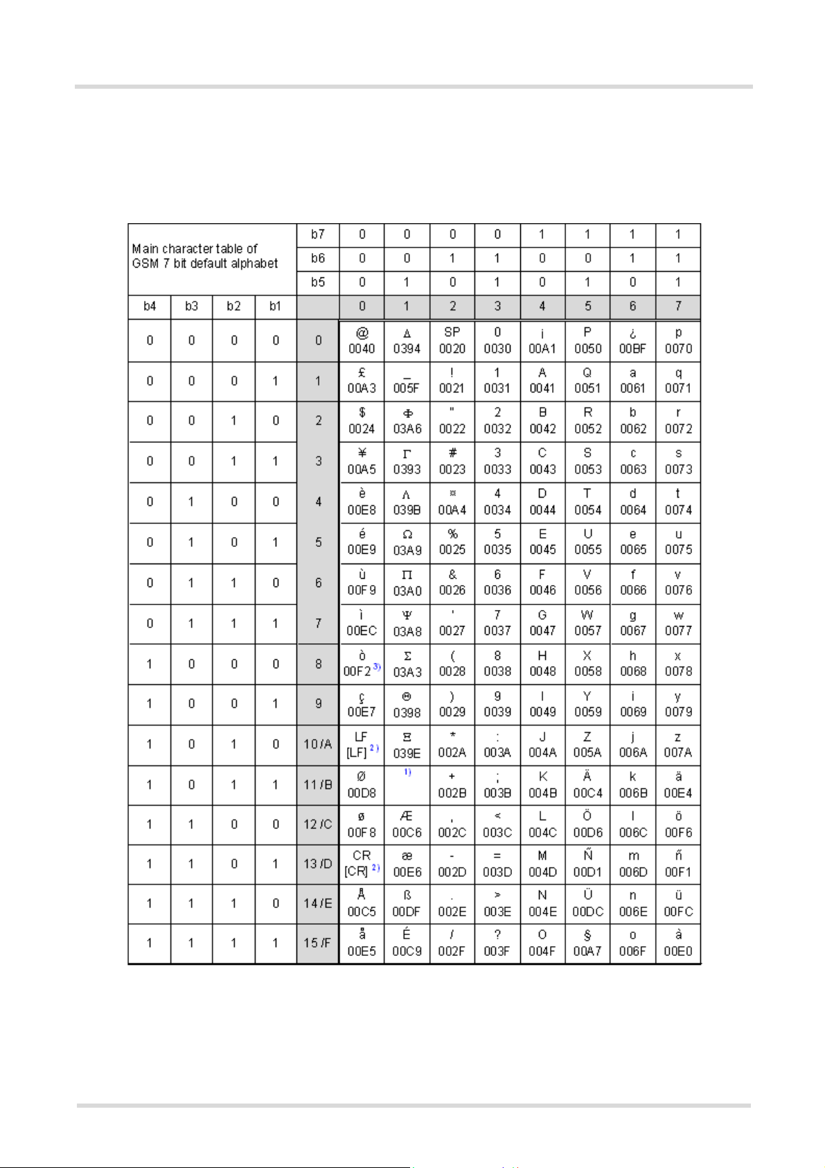
This section provides tables for the GSM default alphabet (3GPP TS 23.038 [35]) supported by the EHS6. Below
any GSM character find the corresponding two byte character value of the UCS2 alphabet. For details refer to
"ETSI GSM 03.38 mapping into Unicode" [14].
Figure 1.1: Main character table of GSM 7 bit default alphabet
1) This code is an escape to the following extension of the 7 bit default alphabet table.
2) This code is not a printable character and therefore not defined for the UCS2 alphabet. It shall be treated as the accom-
panying control character.
3) See Section 1.6 for further details on using backspace and "ò" character.
EHS6_ATC_V03.001 15/12/3
Confidential / Released
Page 25
Cinterion® EHS6 AT Command Set
1.7 Supported character sets
Page 25 of 513
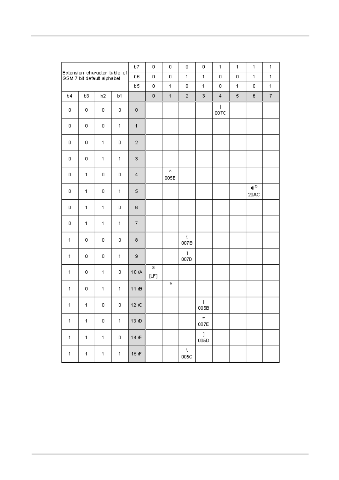
Figure 1.2: Extension character table of GSM 7 bit default alphabet
1) This code value is reserved for the extension to another extension table. On receipt of this code, a receiving entity shall
display a space until another extension table is defined.
2) This code represents the EURO currency symbol. The code value is the one used for the character 'e'. Therefore a receiv-
ing entity which is incapable of displaying the EURO currency symbol will display the character 'e' instead.
3) This code is defined as a Page Break character and may be used for example in compressed CBS messages. Any mobile
which does not understand the 7 bit default alphabet table extension mechanism will treat this character as Line Feed.
EHS6_ATC_V03.001 15/12/3
Confidential / Released
Page 26

Cinterion® EHS6 AT Command Set
1.7 Supported character sets
If the Customer Application receives a code where a symbol is not represented in Figure 1.2, Extension character
table of GSM 7 bit default alphabet it shall display the character shown in the main GSM 7 bit default alphabet
table (see Figure 1.1, Main character table of GSM 7 bit default alphabet).
Page 26 of 513
1.7.2 UCS2 and GSM character coding and conversion
This section provides basic information on how to handle input and output character conversion, e.g. for SMS
text mode, if the character representation of ME and Customer Application differ, i.e. if the Data Coding Scheme
and the TE character set use different mappings.
1.7.2.1 Output of SIM data (ME to TE)
Used character set DCS = 7 bit
GSM
GSM Case 1
GSM (1:1)
UCS2 Case 4
GSM to IRA (1:4)
Note: The ratio of SIM bytes to output bytes is given in parentheses.
Case 1
Every GSM character is sent to the TE as it is (8-bit value with highest bit set to zero).
Example: 47'H, 53'H, 4D'H 47'H, 53'H, 4D'H, displayed as "GSM"
Case 2
Every data byte is sent to the TE as 2 IRA characters each representing a halfbyte.
Example: B8'H (184 decimal) 42'H, 38'H, displayed as "B8"
Case 3
Every 16-bit UCS2 value is sent to the TE as 4 IRA characters.
Example: C4xA7'H (50343 decimal) 43'H, 34'H, 41'H, 37'H, displayed as "C4A7"
Problem: An odd number of bytes leads to an error because there are always two bytes needed for each USC2
character
Case 4
Every GSM character is sent to the TE as 4 IRA characters to show UCS2 in text mode.
Example: 41'H ("A") 30'H, 30'H, 34'H, 31'H, displayed as "0041"
Case 5
Every data byte is sent to the TE as IRA representation of UCS2 (similar to case 4).
Example: B2'H 30'H, 30'H, 42'H, 32'H, displayed as "00B2"
Case 6
Every 16-bit value is sent to the TE as IRA representation of it. It is assumed that number of bytes is even.
Example: C3x46'H 43'H, 33'H, 34'H, 36'H, displayed as "C346"
DCS = 8 bit
Data
Case 2
8 bit to IRA (1:2)
Case 5
8 bit to IRA (1:4)
DCS = 16 bit
UCS2
Case 3
UCS2 to IRA (2:4)
Case 6
UCS2 to IRA (2:4)
EHS6_ATC_V03.001 15/12/3
Confidential / Released
Page 27

Cinterion® EHS6 AT Command Set
1.7 Supported character sets
1.7.2.2 Input of SIM data (TE to ME)
Page 27 of 513
Used character set DCS = 7 bit
GSM
GSM Case 1
GSM (1:1)
UCS2 Case 4
UCS2 to GSM (4:1)
Note: The ratio between the number of input characters and bytes stored on the SIM is given in parentheses.
Case 1
Every character is sent from TE to ME as GSM character (or ASCII with standard terminal emulation, e.g. Hyperterminal®).
Character value must be in range from 0 to 127 because of 7-bit GSM alphabet.
To reach maximum SMS text length of 160 characters in 140 bytes space characters will be compressed on SIM.
This must be set using the parameter <dcs> of AT+CSMP (add 64).
Example: "ABCDEFGH" typed is sent and stored uncompressed as 4142434445464748'H (stored compressed as 41E19058341E91'H)
Case 2
Every data byte is sent as 2 IRA characters.
Maximum text length is 280 IRA characters which will be converted into 140 bytes SMS binary user data
Example: "C8" typed is sent as 43'H, 38'H stored as C8'H
Case 3
Every 16-bit value is sent as 4 IRA characters.
Maximum text length is 280 IRA characters which will be converted into 70 UCS2 characters (16-bit each)
Number of IRA characters must be a multiple of four because always 4 half bytes are needed for a 16-bit value
Example: "D2C8" typed is sent as 44'H, 32'H, 43'H, 38'H stored as D2C8'H
Case 4
Every GSM character is sent as 4 IRA characters representing one UCS2 character.
Example: To store text "ABC" using UCS2 character set you have to type "004100420043".
This is sent as 30'H,30'H,34'H,31'H, 30'H,30'H,34'H,32'H, 30'H,30'H,34'H,33'H detected as IRA representation of 3 UCS2 characters, converted to GSM character set and stored as 41'H, 42'H, 43'H.
Maximum input is 640 IRA characters representing 160 UCS2 characters when compression is active. These
are converted to 160 GSM 7-bit characters.
Without compression only 140 GSM characters can be stored which are put in as 560 IRA characters.
Values of UCS2 characters must be smaller than 80'H (128 decimal) to be valid GSM characters.
Number of IRA characters must be a multiple of four. Problems:
• "41" Error, there are four IRA characters (two bytes) needed
• "0000" Error, not an UCS2 character
• "4142" Error, value of UCS2 character > 7F'H
• "008B"
This affects the maximum input length of a string)
Case 5
Every UCS2 character is sent as 4 IRA characters and is converted into two 8-bit values. This means that the
first two characters have to be '00'.
Example: UCS2 character 009F'H typed as "009F" is sent as 30'H,30'H,39'H,46'H converted into 8-bit value
9F'H.
Maximum number of UCS2 characters is 140 which are represented by 560 IRA characters. Number of IRA characters must be a multiple of four.
Case 6
Every UCS2 character is sent as 4 IRA characters each and is converted into a 16-bit value again.
Example: UCS2 character 9F3A'H typed as "9F3A" is sent as 39'H,46'H,33'H,41'H converted into 9F3A'H.
Maximum number of UCS2 characters is 70 which are represented by 280 IRA characters. Number of IRA characters must be a multiple of four.
Invalid UCS2 values must be prevented.
Error, value of UCS2 character > 7F'H
DCS = 8 bit
Data
Case 2
IRA to 8 bit (2:1)
Case 5
UCS2 to 8 bit (4:1)
DCS = 16 bit
UCS2
Case 3
IRA to 16 bit (4:2)
Case 6
UCS2 to 16 bit (4:2)
EHS6_ATC_V03.001 15/12/3
Confidential / Released
Page 28

Cinterion® EHS6 AT Command Set
Page 28 of 513
1.8 Unsolicited Result Code Presentation
1.8 Unsolicited Result Code Presentation
URC stands for Unsolicited Result Code and is a report message issued by the ME without being requested by
the TE, i.e. a URC is issued automatically when a certain event occurs. Hence, a URC is not issued as part of
the response related to an executed AT command.
Typical events leading to URCs are incoming calls ("RING"), waiting calls, received short messages, changes in
temperature, network registration etc.
For most of these messages, the ME needs to be configured whether or not to send a URC. Descriptions of these
URCs are provided with the associated AT command. URCs which are not user definable are described in Section 1.8.1, Common URCs. A summary of all URCs can be found in Section 21.6, Summary of Unsolicited
Result Codes (URC).
Important: If the interface used for URC output is reserved by an active data connection or a long running AT
command, URCs are buffered internally and will be issued after the interface becomes idle again. A pending
URC will be signaled on the URC output interface via RING line. This allows to systematically suspend any longer
data connection (refer +++ and ATO) to check for pending URCs after being signaled!
For detailed information regarding configuration of URC signaling refer to AT^SCFG, "URC/Ringline", <urcRin-
glineCfg>.
Parameter Description
<info>
(num)
200 URC will be send 40 seconds after powerup when the JRC midlet was not tried
to start (no autostart, no midlet at all, whatever). Used to see in logs, that midlet
is not running, as example.
201 The JRC midlet was started, but did not succeed to full init itself within a (JRC
midlet defined) timeout. 5 seconds after this URC, the ME will restart.
202 The midlet was tried to start 5x, but was restarted (with ^SYSINFO: 201). Now,
the JRC midlet start was cancelled. No JRC midlet is running. A shutdown
timer of 10 minutes is started. After this timer, the ME will be switched off.
1.8.1 Common URCs
This section describes all URCs not associated to a certain AT command. They cannot be defined by the user
and appear automatically when the conditions described below occur.
Notes for "^SBC" URCs reporting undervoltage/overvoltage conditions:
Please refer to [2] for specifications regarding the minimum and maximum operating voltage limits. If the supply
voltage exceeds the defined thresholds the ME switches off automatically. The automatic shutdown procedure
is equivalent to the power-down initiated with the AT^SMSO command.
URC 1
^SYSLOADING
Indicates that the ME is in the process of starting up. Do not enter AT commands until the "^SYSSTART" URC
has shown up.
URC 2
^SYSSTART
Indicates that the ME has been restarted to Normal mode or Airplane mode and is ready to operate.
For Normal and Airplane mode see AT+CFUN.
Note: Autobaud mode (see AT+IPR) requires an "AT" or "at" string be given after restarting the ME. This
enables the ME to detect the bit rate set in the TE. After detecting the bit rate the ME will send the "^SYS-
START" URC.
EHS6_ATC_V03.001 15/12/3
Confidential / Released
Page 29

Cinterion® EHS6 AT Command Set
Page 29 of 513
1.8 Unsolicited Result Code Presentation
URC 3
+PBREADY
After SIM PIN authentication has completed this URC indicates that the ME has completed reading data from
the SIM and that phonebook and SMS functions are ready for read and write operation.
Any attempt to use phonebook or SIM PIN dependent SMS AT commands before the ME has finished reading
SIM data will be denied with error codes, such as "+CME ERROR: SIM busy" or "+CMS ERROR: SIM busy".
URC 4
^SYSINFO: <info>
System information URC.
URC 5
^SBC: Undervoltage Warning
Supply voltage is close to the defined undervoltage threshold.
URC 6
^SBC: Undervoltage Shutdown
Undervoltage threshold exceeded. ME automatically switches off.
URC 7
^SBC: Overvoltage Warning
Supply voltage is close to defined overvoltage threshold.
URC 8
^SBC: Overvoltage Shutdown
Overvoltage threshold exceeded. ME automatically switches off.
EHS6_ATC_V03.001 15/12/3
Confidential / Released
Page 30

Cinterion® EHS6 AT Command Set
1.9 Errors and Messages
Page 30 of 513
1.9 Errors and Messages
The command result codes "+CME ERROR: <err>" and "+CMS ERROR: <err>" indicate errors related to mobile
equipment or network functionality.
The format of <err> can be either numeric or verbose and is selectable via AT+CMEE.
A result error code terminates the execution of the command and prevents the execution of all remaining commands that may follow on the same command line. If so, neither "ERROR" nor "OK" result codes are returned
for these commands. A 30 seconds timeout will deliver "ERROR" when the input of a command is not complete.
Using the wrong command syntax may result in errors: For example, using the execute command syntax
although the command has no execute format, causes "ERROR" to be returned. Likewise, using the write command syntax although the command has no write format causes "+CME ERROR: <err>" to be returned.
See also:
• Section 2.10.1, CME/CMS Error Code Overview
• Section 2.5.1, Verbose and numeric result codes
• Section 3.1, AT+CEER
EHS6_ATC_V03.001 15/12/3
Confidential / Released
Page 31

Cinterion® EHS6 AT Command Set
2. Configuration Commands
Page 31 of 513
2. Configuration Commands
The AT Commands described in this chapter allow the external application to determine the EHS6's behaviour
under various conditions.
2.1 AT&F Reset AT Command Settings to Factory Default Values
AT&F resets AT command settings to their factory default values.
For a list of affected parameters refer to Section 21.5, Factory Default Settings Restorable with
AT&F.
Syntax
Exec Command
AT&F[<value>]
Response(s)
OK
PIN Last Reference(s)
- + - V.250
Parameter Description
<value>
[0] Reset parameters in Section 21.5, Factory Default Settings Restor-
(num)
able with AT&F to their factory default values.
EHS6_ATC_V03.001 15/12/3
Confidential / Released
Page 32

Cinterion® EHS6 AT Command Set
Page 32 of 513
2.2 AT&V
2.2 AT&V Display current configuration
AT&V returns the current parameter setting. The configuration varies depending on whether or not PIN authen-
tication has been done.
Syntax
Exec Command
AT&V[<value>]
Response(s)
ACTIVE PROFILE:
... (see Section 2.2.1, AT&V responses)
OK
PIN Last Reference(s)
- + - V.250
Parameter Description
<value>
[0] Profile number
(num)
Note
• The parameter of AT+CSDH will only be displayed in SMS Text mode, see AT+CMGF.
EHS6_ATC_V03.001 15/12/3
Confidential / Released
Page 33

Cinterion® EHS6 AT Command Set
2.2 AT&V
Page 33 of 513
2.2.1 AT&V responses
The following table shows different kinds of responses depending on whether or not the PIN is entered.
PIN authentication done No PIN authentication
ACTIVE PROFILE:
E1 Q0 V1 X4 &C1 &D2 &S0 \Q3
S0:000 S3:013 S4:010 S5:008 S6:000 S7:060 S8:000
S10:002
+CBST: 7,0,1
+CRLP: 61,61,78,6
+CR: 0
+CRC: 0
+CMGF: 1
+CSDH: 0
+CNMI: 0,0,0,0,1
+ICF: 3
+IPR: 115200
+CMEE: 2
+CSMS: 0,1,1,1
+CREG: 0,1
+CLIP: 0,2
+COPS: 0,0,"operator",0
+CGSMS: 1
OK
ACTIVE PROFILE:
E1 Q0 V1 X4 &C1 &D2 &S0 \Q3
S0:000 S3:013 S4:010 S5:008 S6:000 S7:060 S8:000
S10:002
+CBST: 7,0,1
+CRLP: 61,61,78,6
+CR: 0
+ICF: 3
+IPR: 115200
OK
EHS6_ATC_V03.001 15/12/3
Confidential / Released
Page 34

Cinterion® EHS6 AT Command Set
2.3 AT&W
Page 34 of 513
2.3 AT&W Store AT Command Settings to User Defined Profile
AT&W stores the current AT command settings to a user defined profile in non-volatile memory of EHS6. The AT
command settings will automatically be restored from the user defined profile during power-up or if ATZ is used.
AT&F restores AT command factory default settings. Hence, until first use of AT&W, ATZ works as AT&F.
A list of parameters stored to the user profile can be found at Section 21.4, AT Command Settings storable
with AT&W.
Syntax
Exec Command
AT&W[<value>]
Response(s)
OK
ERROR
+CME ERROR: <err>
PIN Last Reference(s)
- + - V.250
Parameter Description
<value>
[0] User Profile Number
(num)
EHS6_ATC_V03.001 15/12/3
Confidential / Released
Page 35

Cinterion® EHS6 AT Command Set
Page 35 of 513
2.4 ATQ
2.4 ATQ Result Code Presentation Mode
ATQ controls if the EHS6 transmits any result code to the TE. Other information text transmitted as response is
not affected.
Syntax
Exec Command
ATQ[<n>]
Response(s)
If <n>=0:
OK
If <n>=1:
(none)
PIN Last Reference(s)
- + - V.250
Parameter Description
(num)(&V)(&W)
<n>
Result Code Presentation Mode.
It is not recommended to change this value.
(&F)(D)
[0]
1 Result codes are suppressed and not transmitted.
ME transmits result code.
EHS6_ATC_V03.001 15/12/3
Confidential / Released
Page 36

Cinterion® EHS6 AT Command Set
Page 36 of 513
2.5 ATV
2.5 ATV Result code format mode
This command determines the contents of header and trailer transmitted with AT command result codes and
information responses. Possible responses are described in Section 2.5.1, Verbose and numeric result codes.
Syntax
Exec Command
ATV[<value>]
Response(s)
OK
ERROR
PIN Last Reference(s)
- + - ITU-T V.250 [16]
Parameter Description
<value>
(num)(&V)(&W)
[0] Information response: <text><CR><LF>
Short result code format: <numeric code><CR>
(&F)(D)
1
Information response: <CR><LF><text><CR><LF>
Long result code format: <CR><LF><verbose code><CR><LF>
2.5.1 Verbose and numeric result codes
Verbose format Numeric format Meaning
OK 0 command executed, no errors
CONNECT 1 link established
RING 2 ring detected
NO CARRIER 3 link not established or disconnected
ERROR 4 invalid command or command line too long
NO DIALTONE 6 no dial tone, dialling impossible, wrong mode
BUSY 7 remote station busy
NO ANSWER 8 no answer
CONNECT 2400/RLP 10 link with 2400 bps
CONNECT 4800/RLP 11 link with 4800 bps
CONNECT 9600/RLP 12 link with 9600 bps
EHS6_ATC_V03.001 15/12/3
Confidential / Released
Page 37

Cinterion® EHS6 AT Command Set
Page 37 of 513
2.6 ATX
2.6 ATX CONNECT Result Code Format
ATX determines whether or not the EHS6 transmits particular result codes to the TE. It also controls whether or
not the ME verifies the presence of a dial tone when it begins dialing, and if engaged tone (busy signal) detection
is enabled.
Syntax
Exec Command
ATX[<value>]
Response(s)
OK
ERROR
PIN Last Reference(s)
- + - V.250
Parameter Description
<value>
[0] CONNECT result code only returned. Dial tone and busy detection are dis-
1 CONNECT <text> result code only returned. Dial tone and busy detection are
2 CONNECT <text> result code returned. Dial tone detection is enabled, busy
3 CONNECT <text> result code returned. Dial tone detection is disabled, busy
(&F)
4
(num)(&V)(&W)
abled.
both disabled.
detection is disabled.
detection is enabled.
CONNECT <text> result code returned. Dial tone and busy detection are
both enabled.
EHS6_ATC_V03.001 15/12/3
Confidential / Released
Page 38

Cinterion® EHS6 AT Command Set
2.7 ATZ
Page 38 of 513
2.7 ATZ Restore AT Command Settings from User Defined Profile
First ATZ resets the AT command settings to their factory default values, similar to AT&F. Afterwards the AT com-
mand settings are restored from a user defined profile in non-volatile memory of EHS6, if one was stored with
AT&W before. Any additional AT command on the same command line may be ignored. A delay of 300 ms is
required before next AT command can be sent.
Syntax
Exec Command
ATZ[<value>]
Response(s)
OK
PIN Last Reference(s)
- + - V.250
Parameter Description
<value>
[0] User Profile Number
(num)
EHS6_ATC_V03.001 15/12/3
Confidential / Released
Page 39

Cinterion® EHS6 AT Command Set
Page 39 of 513
2.8 AT+CFUN
2.8 AT+CFUN Functionality Level
AT+CFUN controls EHS6's functionality level. It can also be used to reset the ME.
Syntax
Test Command
AT+CFUN=?
Response(s)
+CFUN: (list of supported <fun>s), (list of supported <rst>s)
OK
ERROR
+CME ERROR: <err>
Read Command
AT+CFUN?
Response(s)
+CFUN: <power_mode>, <STK_mode>
OK
ERROR
+CME ERROR: <err>
Write Command
AT+CFUN=<fun>[, <rst>]
Response(s)
OK
ERROR
+CME ERROR: <err>
If <fun>= 0:
OK
^SHUTDOWN
If <rst>= 1:
OK
^SYSSTART
PIN Last Reference(s)
- + - 3GPP TS 27.007 [45]
Parameter Description
(num)
<fun>
0 Switch off ME. ME returns OK followed by "^SHUTDOWN" URC.
See also AT^SMSO command.
(D)
1
4 Airplane mode.
EHS6_ATC_V03.001 15/12/3
Full functionality level.
Shut down TX and RX RF-circuits whereby EHS6 logs off from the network and
switches to AT+COPS=2. All AT commands whose execution requires a radio
connection will return an error response (such as "NO CARRIER" or "+CME
ERROR: NO NETWORK SERVICE". A list of AT commands supported during
Airplane mode can be found in Section 21.3, Availability of AT Com-
mands Depending on Operating Mode of ME.
After leaving Airplane mode by setting AT+CFUN=1 the AT+COPS write command shall be used to register to a network once again.
Confidential / Released
Page 40

Cinterion® EHS6 AT Command Set
Page 40 of 513
2.8 AT+CFUN
6 This mode was implemented in EHS6 Release 1 for activating the USAT inter-
face. As of EHS6 Release 2 the mode is deprecated and no longer effective.
USAT can now be used in Automatic or Explicit Response Mode depending on
AT^SSTA settings.
7 Reserved for future use.
8 Reserved for future use.
(num)
<rst>
Parameter <rst> applies only to <fun> 1 and 4.
[0] ME switches to <fun> level without reset.
1 ME resets and restarts to full functionality level or Airplane mode, depending
on given <fun> value. "^SYSSTART" URC indicates that the ME is ready to
operate.
Note: Autobaud mode (see AT+IPR) requires an "AT" or "at" string be given
after restart. This enables the ME to detect the bit rate set in the TE. After
detecting the bit rate the ME will send the "^SYSSTART" URC.
<power_mode>
(num)
1 ME is switched on
2 Invalid mode
4 Airplane mode
<STK_mode>
(num)
0 Deprecated. See above <fun> value 6.
6 Deprecated. See above <fun> value 6.
7 Reserved for future use.
8 Reserved for future use.
EHS6_ATC_V03.001 15/12/3
Confidential / Released
Page 41

Cinterion® EHS6 AT Command Set
2.9 AT^SMSO
Page 41 of 513
2.9 AT^SMSO Switch Off EHS6
AT^SMSO initiates EHS6's power-off procedure. Do not send any other AT command after this.
Low level of the ME's V180 signal and the URC "^SHUTDOWN" notify that the procedure has completed and the
ME has entered the POWER DOWN mode. Therefore, be sure not to disconnect the operating voltage until the
V180 signal has gone low and until the URC "^SHUTDOWN" is displayed. Otherwise, you run the risk of losing
data. For further details on how to turn off the ME refer to [2]. If a fast switch off (see parameter <fso> in
AT^SCFG) is enabled, there is no reply like OK, ERROR or any "^SHUTDOWN" URC.
Syntax
Test Command
AT^SMSO=?
Response(s)
OK
Exec Command
AT^SMSO
Response(s)
^SMSO: MS OFF
OK
ERROR
PIN Last
- + +
Unsolicited Result Code
^SHUTDOWN
Indicates that the power-off procedure is finished and the module will be switched off in less than 1 second.
If <fso> is used to enable a fast ME switch off, there will be no "^SHUTDOWN" URC.
Note
• If <fso> is used to enable a fast ME switch off, flash access cycles (writing/deleting) will be finalized, but there
will no longer be any network deregistration, the current settings will not be saved and there will be no further
output on the interfaces. All other jobs will be deleted and logical data consistance cannot be guaranteed.
EHS6_ATC_V03.001 15/12/3
Confidential / Released
Page 42

Cinterion® EHS6 AT Command Set
Page 42 of 513
2.10 AT+CMEE
2.10 AT+CMEE Error Message Format
AT+CMEE controls the format of error result codes that indicates errors related to EHS6 functionality. Format can
be selected between plain "ERROR" output, error numbers or verbose "+CME ERROR: <err>" and "+CMS
ERROR: <err>" messages.
Possible error result codes are listed in Table 2.1, General "CME ERROR" Codes (3GPP TS 27.007), Table 2.2,
General "CME ERROR" Codes (proprietary), Table 2.3, GPRS related "CME ERROR" Codes (3GPP TS 27.007)
and Table 2.4, SMS related "CMS ERROR" Codes (3GPP TS 27.005).
Syntax
Test Command
AT+CMEE=?
Response(s)
+CMEE: (list of supported<errMode>s)
OK
Read Command
AT+CMEE?
Response(s)
+CMEE: <errMode>
OK
Write Command
AT+CMEE=<errMode>
Response(s)
OK
ERROR
+CME ERROR: <err>
PIN Last Reference(s)
- + - 3GPP TS 27.007 [45], 3GPP TS
27.005 [44]
Parameter Description
<errMode>
(&F)(D)
0
1 Enable error result code with numeric values.
2 Enable error result code with verbose (string) values.
Example
To obtain enhanced error messages it is recommended to choose <errMode>=2.
AT+CMEE=2
OK
(num)(&V)(&W)
Disable result code, i.e. only "ERROR" will be displayed.
EHS6_ATC_V03.001 15/12/3
Confidential / Released
Page 43

Cinterion® EHS6 AT Command Set
2.10 AT+CMEE
2.10.1 CME/CMS Error Code Overview
Table 2.1: General "CME ERROR" Codes (3GPP TS 27.007)
+CME <err> Code Text (if AT+CMEE=2)
0 phone failure
1 no connection to phone
2 phone adapter link reserved
3 operation not allowed
4 operation not supported
5 PH-SIM PIN required
6 PH-FSIM PIN required
7 PH-FSIM PUK required
10 SIM not inserted
11 SIM PIN required
12 SIM PUK required
13 SIM failure
14 SIM busy
15 SIM wrong
16 incorrect password
17 SIM PIN2 required
18 SIM PUK2 required
20 memory full
21 invalid index
22 not found
23 memory failure
24 text string too long
25 invalid characters in text string
26 dial string too long
27 invalid characters in dial string
30 no network service
31 network timeout
32 network not allowed - emergency calls only
40 network personalization PIN required
41 network personalization PUK required
42 network subset personalization PIN required
43 network subset personalization PUK required
44 service provider personalization PIN required
45 service provider personalization PUK required
46 corporate personalization PIN required
47 corporate personalization PUK required
48 hidden key required
(NOTE: This key is required when accessing hidden phonebook entries.)
49 EAP method not supported
Page 43 of 513
EHS6_ATC_V03.001 15/12/3
Confidential / Released
Page 44

Cinterion® EHS6 AT Command Set
2.10 AT+CMEE
+CME <err> Code Text (if AT+CMEE=2)
50 Incorrect parameters
100 Unknown
256 operation temporary not allowed
257 call barred
261 SS not executed
500 CTS Handover on Progress
501 Cellular Protocol Stack Out of service state
502 CTS Unspecified Error
Table 2.2: General "CME ERROR" Codes (proprietary)
+CME <err> Code Text (if AT+CMEE=2)
615 network failure
616 network is down
639 service type not yet available
640 operation of service temporary not allowed
650 resolve host name failure
764 missing input value
765 invalid input value
767 operation failed
Page 44 of 513
Table 2.3: GPRS related "CME ERROR" Codes (3GPP TS 27.007)
+CME <err> Code Text (if AT+CMEE=2)
103 illegal MS
106 illegal ME
107 GPRS services not allowed
111 PLMN not allowed
112 location area not allowed
113 roaming not allowed in this location area
132 service option not supported
133 requested service option not subscribed
134 service option temporary out of order
148 unspecified GPRS error
149 PDP authentication failure
150 invalid mobile class
151 Unassigned (unallocated) number
152 No route to destination
153 Channel unacceptable
154 Operator determined barring
155 Normal call clearing
156 User busy
157 No user responding
158 User alerting, no answer
EHS6_ATC_V03.001 15/12/3
Confidential / Released
Page 45

Cinterion® EHS6 AT Command Set
2.10 AT+CMEE
+CME <err> Code Text (if AT+CMEE=2)
159 Call rejected
160 Number changed
161 Non selected user clearing
162 Destination out of order
163 Invalid number format (incomplete number)
164 Facility rejected
165 Response to STATUS ENQUIRY
166 Normal, unspecified
167 No circuit/channel available
168 Network out of order
169 Temporary failure
170 Switching equipment congestion
171 Access information discarded
172 requested circuit/channel not available
173 Resources unavailable, unspecified
174 Quality of service unavailable
175 Requested facility not subscribed
176 Incoming calls barred within the CUG
177 Bearer capability not authorized
178 Bearer capability not presently available
179 Service or option not available, unspecified
180 Bearer service not implemented
181 ACM equal to or greater than ACMmax
182 Requested facility not implemented
183 Only restr. digital information bearer capability
184 Service or option not implemented, unspecified
185 Invalid transaction identifier value
186 User not member of CUG
187 Incompatible destination
188 Invalid transit network selection
189 Semantically incorrect message
190 Invalid mandatory information
191 Message type non-existent or not implemented
192 Message type not compatible with protocol state
193 Information element non-existent or not implemented
194 Conditional IE error
195 Message not compatible with protocol state
196 Recovery on timer expiry
197 Protocol error, unspecified
198 Interworking, unspecified
199 Number not allowed
Page 45 of 513
EHS6_ATC_V03.001 15/12/3
Confidential / Released
Page 46

Cinterion® EHS6 AT Command Set
2.10 AT+CMEE
+CME <err> Code Text (if AT+CMEE=2)
200 CCBS possible
596 GPRS - invalid CID value
Table 2.4: SMS related "CMS ERROR" Codes (3GPP TS 27.005)
+CMS <err> Code Text (if AT+CMEE=2)
1 unassigned (unallocated) number
8 operator determined barring
10 call barred
13 SMS timer expired
14 SMS forwarding availability failed
17 Network failure
21 Short message transfer rejected
22 Memory capacity exceeded
27 Destination out of order (service)
28 unidentified subscriber
29 facility rejected
30 unknown subscriber
38 Network out of order (service)
41 temporary failure
42 congestion
47 Resource unavailable, unspecified
50 requested facility not subscribed
69 requested facility not implemented
81 invalid short message transfer reference value
95 Semantically invalid message, unspecified
96 invalid mandatory information
97 message type non-existent or not implemented
98 message not compatible with short message protocol state
99 information element non-existent or not implemented
111 protocol error, unspecified
127 interworking, unspecified
128 telematic interworking not supported
129 short message type 0 not supported
130 cannot replace short message
143 unspecified TP-PID error
144 data coding scheme (alphabet) not supported
145 message class not supported
159 unspecified TP-DCS error
160 command cannot be actioned
161 command unsupported
175 unspecified TP-command error
176 TPDU not supported
Page 46 of 513
EHS6_ATC_V03.001 15/12/3
Confidential / Released
Page 47

Cinterion® EHS6 AT Command Set
2.10 AT+CMEE
+CMS <err> Code Text (if AT+CMEE=2)
192 SC busy
193 no SC subscription
194 SC system failure
195 Invalid Short Message Entity(SME) address (MO)
196 Destination SME barred (MO)
197 SM rejected duplicated SM (MO)
198 TP-VPF (validity period format) not supported (MO)
199 TP-VP (validity period) not supported (MO)
208 (U)SIM SMS storage full (MT)
209 no SMS storage capability in (U)SIM (MT)
210 Error in MS (MT)
211 Memory capacity exceeded (MT)
212 (U)SIM Application Toolkit busy
213 (U)SIM data download error
255 unspecified error cause
287 Network failure unspecified
290 Network no resource
300 ME failure
301 SMS service of ME reserved
302 operation not allowed
303 operation not supported
304 invalid PDU mode parameter
305 invalid text mode parameter
310 SIM not inserted
311 SIM PIN necessary
312 PH-SIM PIN necessary
313 SIM failure
314 SIM busy
315 SIM wrong
320 Memory failure
321 Invalid memory index
322 Memory full
330 SMSC address unknown
331 No network service
332 Network timeout
340 No CNMA acknowledgement expected
500 Unknown error
512 Relay path Acknowledgement
513 SMS timer expired
514 SMS forwarding availability failed
515 SMS forwarding availability aborted
516 Invalid TP-MESSAGE-Type Indicator
Page 47 of 513
EHS6_ATC_V03.001 15/12/3
Confidential / Released
Page 48

Cinterion® EHS6 AT Command Set
2.10 AT+CMEE
+CMS <err> Code Text (if AT+CMEE=2)
517 No TP-Status Report in Phase 1
518 No TP-Reject-Duplicate in Phase 1
519 No TP-Reply-Path in Phase 1
520 No TP-User-Data-Header in Phase 1
521 Missing TP-Validity-Period
522 Invalid TP-Service-Centre-Time-Stamp
523 Missing TP-Destination-Address
524 Invalid TP-Destination-Address
525 Missing Service-Centre-Address
526 Invalid Service-Centre-Address
527 Invalid alphabet
528 Invalid TP-User-Data-Length
529 Missing TP-User-Data
530 TP-User-Data too long(large)
531 No command request in Phase 1
532 Command Request Invalid TP-Destination Address
533 Command Request Invalid TP-User-Data Length
534 Command Request Invalid TP-User-Data
535 Command Request Invalid TP-Command-Type
536 MN MNR creation failed
538 MS Network connection lost
539 Pending MO SM transfer
540 MO SMS rejected by SIM MO SMS control
541 RP ERROR OK
542 RP ERROR OK no icon display
543 FDN check failed
544 Sending of SMS failed. Cause is Service Centre Address (SCA) FDN failed
545 Sending of SMS failed. Cause is Destination Address (DA) FDN failed.
546 BDN check failed
547 Unspecified SMS PP error
548 No Route To Destination
549 Channel Unacceptable
555 No Circuit/Channel Available
556 Access Information Discarded
557 Requested Circuit/Channel Not Available By Other Side
558 Quality Of Service Unavailable
560 Bearer Capability Not Authorized
561 Bearer Capability Not Presently Available
562 Service or Option Not Available, Unspecified
563 Bearer Service Not Implemented
564 ACM Equal to or Greater Than ACMmax
565 Only Restricted Digital Information Bearer Capability Is Available
Page 48 of 513
EHS6_ATC_V03.001 15/12/3
Confidential / Released
Page 49

Cinterion® EHS6 AT Command Set
2.10 AT+CMEE
+CMS <err> Code Text (if AT+CMEE=2)
566 Service or Option Not Implemented, Unspecified
567 User Not Member of CUG
568 Incompatible By Destination
569 Invalid Transit Network Selection
571 Message Not Compatible With Protocol State
572 Recovery On Timer Expiry
576 Data Call Active
577 Speech Call Active
579 MOC Setup Rejected Due to Missing ACM Info
580 Temporary Forbidden Call Attempt
581 Called Party is Blacklisted
583 Temporary Forbidden Call Attempt No Service
584 Temporary Forbidden Call Attempt Limited Service
585 Client Temporary Barred
587 Atc Fclass Not Speech
590 Client Not Registrated
591 Active Client Gone
595 Rejected By Call Control
604 MM No Service (out of coverage)
605 MM Access Class Barred (RR_REL_IND During RR Conn. Establishment
606 ME Busy -CM Service Request Already Pending
608 Rejected Due To SUP Timer Expiry
609 Rejected Due To USSD Busy
610 Rejected Due To SS Busy
610 Rejected Due To SS Busy
612 SIM Toolkit Request Is Rejected, Because Another SIM Toolkit Request Is Pend-
ing
614 Rejected Because SIM Toolkit Request Is Not Yet Answered By The User
615 MN Setup SS Error
615 MN Setup SS Error
616 Call Controller Blocked (Other Call Command Pending)
618 Environment Parameter Not Set Correctly (Fclass/Cmod)
619 Other Blocking Call Present
620 Lower Layer Failure
621 The Authentication Proedure Failed
622 The Packet-Switched Registration Procedure Failed
623 CM Service Reject From The Network
624 The ABORT Message Was Received From The Network
625 Timer Expiry
626 IMSI Deatch Was Initiated
627 Normal RR Connection Release (2G)
628 Registration Failed
Page 49 of 513
EHS6_ATC_V03.001 15/12/3
Confidential / Released
Page 50

Cinterion® EHS6 AT Command Set
2.10 AT+CMEE
+CMS <err> Code Text (if AT+CMEE=2)
630 Failure Due To Handover
631 Link Establishment Failure
632 Random Access Failure
633 Radio Link Aborted
634 Lower Layer Failure in Layer 1
635 Immediate Assignment Reject
636 Failure Due To Paging
637 Abnormal Release Unspecified
638 Abnormal Release Channel Unacceptable
639 Abnormal Release Timer Expired
640 Abnormal Release No Act On Radio Path
641 Preemptive Release
642 UTRAN Configuration Unknown
643 Handover Impossible
644 Channel Mode Unacceptable
647 Lower Layer Failure From NW
649 Conditional IE Error
650 No Cell Allocation Available
653 Re Establishment Reject
654 Directed Sigconn Re Establishment
656 Release of RRC connection Witout Network Activity(3G) Lower Layer Failure
Downlink
657 Lower Layer Failure Uplink
658 Cell Barred Due To Authentication Failure
659 Signalling Connection Release
660 CS Connection Release Triggered By MM
661 RRC Connection Establishment Failure
662 RRC Connection Establsihment Reject With Redirection
663 Resource Conflict
664 Layer Layer Failure in Layer 2
665 L2 Cause T200 Expiry N200 Plus 1 Times
669 RR Connection Release Due to BAND Change (2G)
670 Release of the RRC Connection Due to Out of Service in Cell_Fach (3G)"
671 Release of the RRC Connection Due to Not Matching PLMN in Shared Net-
works(3G)
672 Error Happens While Call Is Already Disconnected / Late Error
674 SIM Toolkit Cannot Initiate A Call, Because MMI Is Not Registered
675 SIM Toolkit Call Setup Request Is Rejected Due User Did Not Accept
676 Proactive SIM Appl Terminated By User
677 SIM Toolkit Originated SIM Reset (Refresh Request)
680 Dial String/Number Incorrect
Page 50 of 513
EHS6_ATC_V03.001 15/12/3
Confidential / Released
Page 51

Cinterion® EHS6 AT Command Set
Page 51 of 513
2.11 AT+CSCS
2.11 AT+CSCS Character Set
AT+CSCS write command informs the EHS6 which character set is used by the TE. This enables the ME to con-
vert character strings correctly between TE and ME character sets. Please also refer to Section 1.7, Supported
character sets.
Note: If ME-TE interface is set to 8-bit operation (AT+ICF) and selected character set is <chset>="GSM" (7-
bit), the highest bit will be set to zero.
Syntax
Test Command
AT+CSCS=?
Response(s)
+CSCS: (list of supported<chset>s)
OK
Read Command
AT+CSCS?
Response(s)
+CSCS: <chset>
OK
Write Command
AT+CSCS=<chset>
Response(s)
OK
ERROR
+CME ERROR: <err>
PIN Last Reference(s)
- + - 3GPP TS 27.007 [45]
Parameter Description
<chset>
“GSM“
“UCS2“ 16-bit universal multiple-octet coded character set (ISO-10646 [13]). UCS2
(str)(&W)
(&F)(D)
GSM 7 bit default alphabet (3GPP TS 23.038 [35], Subclause 6.2.1).
character strings are converted to hexadecimal numbers in the range 0000 to
FFFF; e.g. "004100620063" equates to three 16-bit characters with decimal
values 65, 98 and 99.
EHS6_ATC_V03.001 15/12/3
Confidential / Released
Page 52

Cinterion® EHS6 AT Command Set
2.12 AT^SCFG
Page 52 of 513
2.12 AT^SCFG Extended Configuration Settings
AT^SCFG can be used to query and configure various settings of the EHS6.
AT^SCFG read command returns a list of all supported parameters and their current values.
AT^SCFG write command queries a configuration parameter (if no value is entered) or sets its value(s).
Input of parameter names is always coded in GSM character set, parameter values are expected to be given as
specified via AT+CSCS.
Syntax
Test Command
AT^SCFG=?
Response(s)
^SCFG: "Audio/Loop", (list of supported <al>s)
^SCFG: "Call/Ecall/AckTimeout", (list of supported <acktimeout>s)
^SCFG: "Call/Ecall/Callback", (list of supported <callback>s)
^SCFG: "Call/Ecall/CallbackTimeout", (list of supported <callbacktimeout>s)
^SCFG: "Call/Ecall/Msd", (length of <msd>s)
^SCFG: "Call/Ecall/Pullmode", (list of supported <pullmode>s)
^SCFG: "Call/Ecall/SessionTimeout", (list of supported <sessiontimeout>s)
^SCFG: "Call/Ecall/StartTimeout", (list of supported <starttimeout>s)
^SCFG: "Call/ECC", (list of supported <ecc>s)
^SCFG: "Call/Speech/Codec", (list of supported <scc>s)
^SCFG: "GPIO/mode/ASC1", (list of supported <g_mode>s)
^SCFG: "GPIO/mode/DAI", (list of supported <g_mode>s)
^SCFG: "GPIO/mode/DCD0", (list of supported <g_mode>s)
^SCFG: "GPIO/mode/DSR0", (list of supported <g_mode>s)
^SCFG: "GPIO/mode/DTR0", (list of supported <g_mode>s)
^SCFG: "GPIO/mode/FSR", (list of supported <g_mode>s)
^SCFG: "GPIO/mode/HSIC", (list of supported <g_mode>s)
^SCFG: "GPIO/mode/PULSE", (list of supported <g_mode>s)
^SCFG: "GPIO/mode/PWM", (list of supported <g_mode>s)
^SCFG: "GPIO/mode/RING0", (list of supported <g_mode>s)
^SCFG: "GPIO/mode/SPI", (list of supported <g_mode>s)
^SCFG: "GPIO/mode/SYNC", (list of supported <g_mode>s)
^SCFG: "GPRS/AutoAttach", (list of supported <gaa>s)
^SCFG: "MEopMode/CFUN", (list of supported <cfun>s), (list of supported <cfun_save>s)
^SCFG: "MEopMode/Dormancy", (list of supported <dormancy>s)
^SCFG: "MEopMode/SoR", (list of supported <SoR mode>s)
^SCFG: "Ident/Manufacturer", (max. string length of <manufacturer>)
^SCFG: "Ident/Product", (max. string length of <product>)
^SCFG: "MEShutdown/Fso", (list of supported <fso>s)
^SCFG: "MEShutdown/sVsup/threshold", (list of supported <vthresh>s), (list of supported
<PowerSupplyDomain>s)
^SCFG: "Radio/Band", (list of supported <rba>s)
^SCFG: "Radio/Mtpl", (list of supported <PL_mode>s), (list of supported <PL_profile>s), (list of supported
<rba>s), (list of supported <PL_limit>s), (list of supported <PL_limit8psk>s)
^SCFG: "Radio/OutputPowerReduction", (list of supported <ropr>s)
^SCFG: "Serial/Interface/Allocation", (list of supported <curSerialIfcAlloc>s), (list of supported
<reqSerialIfcAlloc>s)
^SCFG: "Serial/USB/DDD" , (list of supported <deviceDescr>s) , (list of supported <descrIndex>s) ,
(max. string length of <langId>) , (max. string length of <vendorId>) , (max. string length of
<productId>) , (max. string length of <manufacturer>) , (max. string length of <product>) , (max. string
length of <serialNo>)
^SCFG: "Tcp/IRT", (list of supported <tcpIrt>)
^SCFG: "Tcp/MR", (list of supported <tcpMr>)
^SCFG: "Tcp/OT", (list of supported <tcpOt>)
EHS6_ATC_V03.001 15/12/3
Confidential / Released
Page 53

Cinterion® EHS6 AT Command Set
Page 53 of 513
2.12 AT^SCFG
Test Command (Continued)
AT^SCFG=?
Response(s)
^SCFG: "Tcp/WithURCs", (list of supported <tcpWithUrc>)
^SCFG: "Trace/Syslog/OTAP", (list of supported <otapTracer>), (list of supported <uwDevice>), (list of
supported <intvalue>), (max. string length of <filename>), (list of supported <logmode>), (list of
supported <blockmode>)
^SCFG: "URC/Ringline", (list of supported <urcRinglineCfg>s)
^SCFG: "URC/Ringline/ActiveTime", (list of supported <urcRinglineDuration>s)
^SCFG: "Userware/Autostart", (list of supported <ua>s)
^SCFG: "Userware/Autostart/Delay", (list of supported <uad>s)
^SCFG: "Userware/DebugInterface", (max. string lengths of <udbgif1>), (max. string lengths of
<udbgif2>), (max. string lengths of <udbgif3>)
^SCFG: "Userware/DebugMode", (list of supported <userwaremode>)
^SCFG: "Userware/Passwd", (max. string length of <upwd>)
^SCFG: "Userware/Stdout", (list of supported <uwDevice>), (list of supported <intvalue>), (max. string
lengths of <filename>), (list of supported <logmode>), (list of supported <blockmode>)
^SCFG: "Userware/Watchdog", (list of supported <wd>)
OK
Read Command
AT^SCFG?
Response(s)
^SCFG: "Audio/Loop", <al>
^SCFG: "Call/Ecall/AckTimeout", <acktimeout>
^SCFG: "Call/Ecall/Callback", <callback>
^SCFG: "Call/Ecall/CallbackTimeout", <callbacktimeout>
^SCFG: "Call/Ecall/Msd", <msd>
^SCFG: "Call/Ecall/Pullmode", <pullmode>
^SCFG: "Call/Ecall/SessionTimeout", <sessiontimeout>
^SCFG: "Call/Ecall/StartTimeout", <starttimeout>
^SCFG: "Call/ECC", <ecc>
^SCFG: "Call/Speech/Codec", <scc>
^SCFG: "GPIO/mode/ASC1", <g_mode>
^SCFG: "GPIO/mode/DAI", <g_mode>
^SCFG: "GPIO/mode/DCD0", <g_mode>
^SCFG: "GPIO/mode/DSR0", <g_mode>
^SCFG: "GPIO/mode/DTR0", <g_mode>
^SCFG: "GPIO/mode/FSR", <g_mode>
^SCFG: "GPIO/mode/HSIC", <g_mode>
^SCFG: "GPIO/mode/PULSE", <g_mode>
^SCFG: "GPIO/mode/PWM", <g_mode>
^SCFG: "GPIO/mode/RING0", <g_mode>
^SCFG: "GPIO/mode/SPI", <g_mode>
^SCFG: "GPIO/mode/SYNC", <g_mode>
^SCFG: "GPRS/AutoAttach", <gaa>
^SCFG: "MEopMode/CFUN", <cfun>, <cfun_save>
^SCFG: "MEopMode/Dormancy", <dormancy>, <eCallUSIM>
^SCFG: "MEopMode/SoR", <SoR mode>
^SCFG: "Ident/Manufacturer", <manufacturer>
^SCFG: "Ident/Product", <product>
^SCFG: "MEShutdown/Fso", <fso>
^SCFG: "MEShutdown/sVsup/threshold", <vthresh_BB_curr>, <vthresh_BB_request>
^SCFG: "Radio/Band", <rba>
^SCFG: "Radio/Mtpl", <PL_mode>[, <PL_profile>]
^SCFG: "Radio/OutputPowerReduction", <ropr>
^SCFG: "Serial/Interface/Allocation", <curSerialIfcAlloc>, <reqSerialIfcAlloc>
EHS6_ATC_V03.001 15/12/3
Confidential / Released
Page 54

Cinterion® EHS6 AT Command Set
Page 54 of 513
2.12 AT^SCFG
Read Command (Continued)
AT^SCFG?
Response(s)
^SCFG: "Serial/USB/DDD" , <deviceDescr>, <descrIndex>, <langId>, <vendorId>, <productId>,
<manufacturer>, <product>, <serialNo>
^SCFG: "Tcp/IRT", <tcpIrt>
^SCFG: "Tcp/MR", <tcpMr>
^SCFG: "Tcp/OT", <tcpOt>
^SCFG: "Tcp/WithURCs", <tcpWithUrc>
^SCFG: "Trace/Syslog/OTAP", <otapTracer>[, <uwDevice>, <intvalue>, <filename>), <logmode>,
<blockmode>]
^SCFG: "URC/Ringline", <urcRinglineCfg>
^SCFG: "URC/Ringline/ActiveTime", <urcRinglineDuration>
^SCFG: "Userware/Autostart", <ua>
^SCFG: "Userware/Autostart/Delay", <uad>
^SCFG: "Userware/DebugInterface", <udbgif1>, <udbgif2>, <udbgif3>
^SCFG: "Userware/DebugMode", <userwaremode>
^SCFG: "Userware/Passwd"
^SCFG: "Userware/Stdout", <uwDevice>[, <intvalue>[, <filename>[, <logmode>]]], <blockmode>
^SCFG: "Userware/Watchdog", <wd>
OK
Write Command
Configure Audio Loop:
AT^SCFG="Audio/Loop"[, <al>]
Response(s)
^SCFG: "Audio/Loop", <al>
OK
ERROR
+CME ERROR: <err>
Write Command
Select eCall ACK timeout in milliseconds.
AT^SCFG="Call/Ecall/AckTimeout"[, <acktimeout>]
Response(s)
^SCFG: "Call/Ecall/AckTimeout", <acktimeout>
OK
ERROR
+CME ERROR: <err>
Write Command
Configure the inband modem for mobile terminate calls.
AT^SCFG="Call/Ecall/Callback"[, <callback>]
Response(s)
^SCFG: "Call/Ecall/Callback"
OK
ERROR
+CME ERROR: <err>
Write Command
Select eCall callback timeout in milliseconds.
AT^SCFG="Call/Ecall/CallbackTimeout"[, <callbacktimeout>]
Response(s)
^SCFG: "Call/Ecall/CallbackTimeout", <callbacktimeout>
OK
EHS6_ATC_V03.001 15/12/3
Confidential / Released
Page 55

Cinterion® EHS6 AT Command Set
Page 55 of 513
2.12 AT^SCFG
Write Command (Continued)
Select eCall callback timeout in milliseconds.
AT^SCFG="Call/Ecall/CallbackTimeout"[, <callbacktimeout>]
Response(s)
ERROR
+CME ERROR: <err>
Write Command
Select Msd data for eCall.
AT^SCFG="Call/Ecall/Msd"[, <msd>]
Response(s)
^SCFG: "Call/Ecall/Msd", <msd>
OK
ERROR
+CME ERROR: <err>
Write Command
Control Inband modem for Pull mode.
AT^SCFG="Call/Ecall/Pullmode"[, <pullmode>]
Response(s)
^SCFG: "Call/Ecall/Pullmode", <pullmode>
OK
ERROR
+CME ERROR: <err>
Write Command
Select eCall start timeout in milliseconds.
AT^SCFG="Call/Ecall/StartTimeout"[, <starttimeout>]
Response(s)
^SCFG: "Call/Ecall/StartTimeout", <starttimeout>
OK
ERROR
+CME ERROR: <err>
Write Command
Select eCall session timeout in milliseconds.
AT^SCFG="Call/Ecall/SessionTimeout"[, <sessiontimeout>]
Response(s)
^SCFG: "Call/Ecall/SessionTimeout", <sessiontimeout>
OK
ERROR
+CME ERROR: <err>
Write Command
Query/Configure Emergency numbers for USIM without ECC field
AT^SCFG="Call/ECC"[, <ecc>]
Response(s)
^SCFG: "Call/ECC", <ecc>
OK
ERROR
+CME ERROR: <err>
EHS6_ATC_V03.001 15/12/3
Confidential / Released
Page 56

Cinterion® EHS6 AT Command Set
Page 56 of 513
2.12 AT^SCFG
Write Command
Query/Configure 2G Speech Codec for voice calls
AT^SCFG="Call/Speech/Codec"[, <scc>]
Response(s)
^SCFG: "Call/Speech/Codec", <scc>
OK
ERROR
+CME ERROR: <err>
Write Command
Configure ASC1 interface lines RXD1, TXD1, RTS1, CTS1 shared with GPIO16 - GPIO19 lines and SPI lines
MOSI, MISO, SPI_CS
AT^SCFG="GPIO/mode/ASC1"[, <g_mode>]
Response(s)
^SCFG: "GPIO/mode/ASC1", <g_mode>
OK
ERROR
+CME ERROR: <err>
Write Command
Configure Digital Audio Interface lines TXDDAI, RXDDAI, TFSDAI, SCLK shared with GPIO20 - GPIO23 lines
AT^SCFG="GPIO/mode/DAI"[, <g_mode>]
Response(s)
^SCFG: "GPIO/mode/DAI", <g_mode>
OK
ERROR
+CME ERROR: <err>
Write Command
Configure DCD0 line of ASC0 interface shared with GPIO2
AT^SCFG="GPIO/mode/DCD0"[, <g_mode>]
Response(s)
^SCFG: "GPIO/mode/DCD0", <g_mode>
OK
ERROR
+CME ERROR: <err>
Write Command
Configure DSR0 line of ASC0 interface shared with GPIO3 line and SPI_CLK line of SPI
AT^SCFG="GPIO/mode/DSR0"[, <g_mode>]
Response(s)
^SCFG: "GPIO/mode/DSR0", <g_mode>
OK
ERROR
+CME ERROR: <err>
Write Command
Configure DTR0 line of ASC0 interface shared with GPIO1 line
AT^SCFG="GPIO/mode/DTR0"[, <g_mode>]
Response(s)
^SCFG: "GPIO/mode/DTR0", <g_mode>
OK
ERROR
+CME ERROR: <err>
EHS6_ATC_V03.001 15/12/3
Confidential / Released
Page 57

Cinterion® EHS6 AT Command Set
Page 57 of 513
2.12 AT^SCFG
Write Command
Configure Fast Shutdown line FST_SHDN shared with GPIO4 line
AT^SCFG="GPIO/mode/FSR"[, <g_mode>]
Response(s)
^SCFG: "GPIO/mode/FSR", <g_mode>
OK
ERROR
+CME ERROR: <err>
Write Command
Configure HSIC interface shared with GPIO16 - GPIO19 lines, ASC1 lines and SPI lines MOSI, MISO, SPI_CS
AT^SCFG="GPIO/mode/HSIC"[, <g_mode>]
Response(s)
^SCFG: "GPIO/mode/HSIC", <g_mode>
OK
ERROR
+CME ERROR: <err>
Write Command
Configure Impulse Counter line (COUNTER) shared with GPIO8 line
AT^SCFG="GPIO/mode/PULSE"[, <g_mode>]
Response(s)
^SCFG: "GPIO/mode/PULSE", <g_mode>
OK
ERROR
+CME ERROR: <err>
Write Command
Configure DAC Pulse-Width Modulation lines PWM2 and PWM1 shared with GPIO6 and GPIO7 lines
AT^SCFG="GPIO/mode/PWM"[, <g_mode>]
Response(s)
^SCFG: "GPIO/mode/PWM", <g_mode>
OK
ERROR
+CME ERROR: <err>
Write Command
Configure RING0 line of ASC0 interface shared with GPIO24 line
AT^SCFG="GPIO/mode/RING0"[, <g_mode>]
Response(s)
^SCFG: "GPIO/mode/RING0", <g_mode>
OK
ERROR
+CME ERROR: <err>
Write Command
Configure SPI lines MOSI, MISO, SPI_CS shared with ASC1 lines and GPIO16, GPIO17, GPIO19 lines
as well as SPI line SPI_CLK shared with GPIO3 and DSR0 of ASC0
AT^SCFG="GPIO/mode/SPI"[, <g_mode>]
Response(s)
^SCFG: "GPIO/mode/SPI", <g_mode>
OK
ERROR
+CME ERROR: <err>
EHS6_ATC_V03.001 15/12/3
Confidential / Released
Page 58

Cinterion® EHS6 AT Command Set
Page 58 of 513
2.12 AT^SCFG
Write Command
Configure Status LED line shared with GPIO5 line
AT^SCFG="GPIO/mode/SYNC"[, <g_mode>]
Response(s)
^SCFG: "GPIO/mode/SYNC", <g_mode>
OK
ERROR
+CME ERROR: <err>
Write Command
Automatic GPRS attach
AT^SCFG="GPRS/AutoAttach"[, <gaa>]
Response(s)
^SCFG: "GPRS/AutoAttach", <gaa>
OK
ERROR
+CME ERROR: <err>
Write Command
Enable/disable non volatile storage of AT+CFUN.
AT^SCFG="MEopMode/CFUN"[, <cfun>]
Response(s)
^SCFG: "MEopMode/CFUN", <cfun>, <cfun_save>
OK
ERROR
+CME ERROR: <err>
Write Command
AT^SCFG="MEopMode/Dormancy"[, <dormancy>]
Response(s)
^SCFG: "MEopMode/Dormancy", <dormancy>, <eCallUSIM>
OK
ERROR
+CME ERROR: <err>
Write Command
Query/Configure steering of roaming
AT^SCFG="MEopMode/SoR"[, <SoR mode>]
Response(s)
^SCFG: "MEopMode/SoR", <SoR mode>
OK
ERROR
+CME ERROR: <err>
Write Command
Configure manufacturer name.
AT^SCFG="Ident/Manufacturer"[, <manufacturer>]
Response(s)
^SCFG: "Ident/Manufacturer", <manufacturer>
OK
ERROR
+CME ERROR: <err>
EHS6_ATC_V03.001 15/12/3
Confidential / Released
Page 59

Cinterion® EHS6 AT Command Set
Page 59 of 513
2.12 AT^SCFG
Write Command
Configure product name.
AT^SCFG="Ident/Product"[, <product>]
Response(s)
^SCFG: "Ident/Product", <product>
OK
ERROR
+CME ERROR: <err>
Write Command
Enable/disable fast switch off.
AT^SCFG="MEShutdown/Fso"[, <fso>]
Response(s)
^SCFG: "MEShutdown/Fso", <fso>
OK
ERROR
+CME ERROR: <err>
Write Command
Query / configure undervoltage threshold
AT^SCFG="MEShutdown/sVsup/threshold"[, <vthresh>][, <PowerSupplyDomain>]
Response(s)
^SCFG: "MEShutdown/sVsup/threshold", <vthresh_BB_curr>, <vthresh_BB_request>
OK
ERROR
+CME ERROR: <err>
Write Command
Radio band selection
AT^SCFG="Radio/Band"[, <rba>]
Response(s)
^SCFG: "Radio/Band", <rba>
OK
ERROR
+CME ERROR: <err>
Write Command
Instant Power Limitation for SAR Reduction and Thermal Mitigation
AT^SCFG="Radio/Mtpl"[, <PL_mode>[, <PL_profile>, <rba>, <PL_limit>[, <PL_limit8psk>]]]
Response(s)
^SCFG: "Radio/Mtpl", <PL_mode>[, <PL_profile>, <rba>, <PL_limit>[, <PL_limit8psk>]]
In case of: <PL_mode>=0
^SCFG: "Radio/Mtpl", <PL_mode>
In case of: <PL_mode>=1 and <PL_profile>
^SCFG: "Radio/Mtpl", <PL_mode>, <PL_profile>
In case of: <PL_mode>=2 and <PL_profile> one profile configuration is printed out
^SCFG: "Radio/Mtpl", <PL_mode>, <PL_profile>, <rba>, <PL_limit>[, <PL_limit8psk>]
^SCFG: ["Radio/Mtpl", <PL_mode>, <PL_profile>, <rba>, <PL_limit>[, <PL_limit8psk>]]
^SCFG: ["Radio/Mtpl",...]
In case of: <PL_mode>=2 full profile configuration (1-8) is printed out
EHS6_ATC_V03.001 15/12/3
Confidential / Released
Page 60

Cinterion® EHS6 AT Command Set
Page 60 of 513
2.12 AT^SCFG
Write Command (Continued)
Instant Power Limitation for SAR Reduction and Thermal Mitigation
AT^SCFG="Radio/Mtpl"[, <PL_mode>[, <PL_profile>, <rba>, <PL_limit>[, <PL_limit8psk>]]]
Response(s)
^SCFG: "Radio/Mtpl", <PL_mode>, <PL_profile>, <rba>, <PL_limit>[, <PL_limit8psk>]
^SCFG: ["Radio/Mtpl", <PL_mode>, <PL_profile>, <rba>, <PL_limit>[, <PL_limit8psk>]]
^SCFG: ["Radio/Mtpl", <PL_mode>, <PL_profile>, <rba>, <PL_limit>[, <PL_limit8psk>]]
^SCFG: ["Radio/Mtpl",...]
In case of: <PL_mode>=3 and <PL_profile>, <rba>,<PL_limit>[,<PL_limit8psk>] only the enabled
profile is printed out
^SCFG: "Radio/Mtpl", <PL_mode>[, <PL_profile>]
OK
ERROR
+CME ERROR: <err>
Write Command
Radio output power reduction
AT^SCFG="Radio/OutputPowerReduction"[, <ropr>]
Response(s)
^SCFG: "Radio/OutputPowerReduction", <ropr>
OK
ERROR
+CME ERROR: <err>
Write Command
Configure allocation of serial interfaces:
AT^SCFG="Serial/Interface/Allocation"[, <reqSerialIfcAlloc>]
Response(s)
^SCFG: "Serial/Ifc", <curSerialIfcAlloc>, <reqSerialIfcAlloc>
OK
ERROR
+CME ERROR: <err>
Write Command
USB Device Descriptor:
AT^SCFG="Serial/USB/DDD" [, <deviceDescr>, [<descrIndex>], [<langId>], <vendorId>,
<productId>, [<manufacturer>], [<product>], [<serialNo>]]
Response(s)
^SCFG: "Serial/USB/DDD" , <deviceDescr>, <descrIndex>, <langId>, <vendorId>, <productId>,
<manufacturer>, <product>, <serialNo>
OK
ERROR
+CME ERROR: <err>
Write Command
Configuration of TCP parameter 'InitialRetransmissionTimeout':
AT^SCFG="Tcp/IRT"[, <tcpIrt>]
Response(s)
^SCFG: "Tcp/IRT", <tcpIrt>
OK
ERROR
+CME ERROR: <err>
EHS6_ATC_V03.001 15/12/3
Confidential / Released
Page 61

Cinterion® EHS6 AT Command Set
Page 61 of 513
2.12 AT^SCFG
Write Command
Configuration of TCP parameter 'MaxRetransmissions':
AT^SCFG="Tcp/MR"[, <tcpMr>]
Response(s)
^SCFG: "Tcp/MR", <tcpMr>
OK
ERROR
+CME ERROR: <err>
Write Command
Configuration of TCP parameter 'OverallTimeout':
AT^SCFG="Tcp/OT"[, <tcpOt>]
Response(s)
^SCFG: "Tcp/OT", <tcpOt>
OK
ERROR
+CME ERROR: <err>
Write Command
Configuration of Internet Service URCs:
AT^SCFG="Tcp/WithURCs"[, <tcpWithUrc>]
Response(s)
^SCFG: "Tcp/WithURCs", <tcpWithUrc>
OK
ERROR
+CME ERROR: <err>
Write Command
Tracing:
AT^SCFG="Trace/Syslog/OTAP"[, <otapTracer>][, <uwDevice>[, <intvalue>][, <filename>][,
<logmode>]][, <blockmode>]
Response(s)
^SCFG: "Trace/Syslog/OTAP", <otapTracer>[, <uwDevice>[, <intvalue>][, <filename>][,
<logmode>][, <blockmode>]]
SYSLOG ENABLED
OK
ERROR
+CME ERROR: <err>
Write Command
Subcommand controls the behaviour of the RING line if it is selected for URC signalization.
AT^SCFG="URC/Ringline"[, <urcRinglineCfg>]
Response(s)
^SCFG: "URC/Ringline", <urcRinglineCfg>
OK
ERROR
+CME ERROR: <err>
Write Command
Subcommand controls duration of active RING line if it is selected for URC signalization.
AT^SCFG="URC/Ringline/ActiveTime"[, <urcRinglineDuration>]
Response(s)
^SCFG: "URC/Ringline/ActiveTime", <urcRinglineDuration>
OK
EHS6_ATC_V03.001 15/12/3
Confidential / Released
Page 62

Cinterion® EHS6 AT Command Set
Page 62 of 513
2.12 AT^SCFG
Write Command (Continued)
Subcommand controls duration of active RING line if it is selected for URC signalization.
AT^SCFG="URC/Ringline/ActiveTime"[, <urcRinglineDuration>]
Response(s)
ERROR
+CME ERROR: <err>
Write Command
Userware autostart status:
AT^SCFG="Userware/Autostart"[, <upwd>, <ua>]
Response(s)
^SCFG: "Userware/Autostart"[, <ua>]
OK
ERROR
+CME ERROR: <err>
Write Command
Userware autostart delay:
AT^SCFG="Userware/Autostart/Delay"[, <upwd>, <uad>]
Response(s)
^SCFG: "Userware/Autostart/Delay"[, <uad>]
OK
ERROR
+CME ERROR: <err>
Write Command
Userware debug interface:
AT^SCFG="Userware/DebugInterface"[, <udbgif1>, <udbgif2>[, <udbgif3>]]
Response(s)
^SCFG: "Userware/DebugInterface", <udbgif1>, <udbgif2>, <udbgif3>
OK
ERROR
+CME ERROR: <err>
Write Command
AT^SCFG="Userware/DebugMode"[, <userwaremode>]
Response(s)
^SCFG: "Userware/DebugMode"[, <userwaremode>]
Write Command
Userware configuration password:
AT^SCFG="Userware/Passwd"[, <upwd>
Response(s)
, <upwd>
old
, <upwd>
new
new
]
^SCFG: "Userware/Passwd"
OK
ERROR
+CME ERROR: <err>
EHS6_ATC_V03.001 15/12/3
Confidential / Released
Page 63

Cinterion® EHS6 AT Command Set
Page 63 of 513
2.12 AT^SCFG
Write Command
Standard output of userware:
AT^SCFG="Userware/Stdout"[, <uwDevice>[, <intvalue>][, <filename>][, <logmode>]][,
<blockmode>]
Response(s)
^SCFG: "Userware/Stdout" , <uwDevice>[, <intvalue>[, <filename>[, <logmode>]]], <blockmode>
OK
ERROR
+CME ERROR: <err>
Write Command
Watchdog configuration and control:
AT^SCFG="Userware/Watchdog"[, <wd>]
Response(s)
^SCFG: "Watchdog", <wd>
OK
ERROR
+CME ERROR: <err>
PIN Last
- ± -
Parameter Description
(str)
<al>
Audio Loop Setting
This parameter can be used to configure an audio loop for performing a simple verification of audio connections.
The feature is intended for testing only.
Neither a USIM nor a mobile network is necessary to turn the audio loop on. Audio mode can be selected via
AT command AT^SNFS. Audio path can be selected via AT command AT^SAIC.
In audio loop mode, don't try to change any audio settings (even though changes are accepted) such as interface, mode, volume etc. If you want to change these settings, do it before you turn on the audio loop.
(P)
“0“
“1“ Audio loop active
<acktimeout>
(str)
eCall ACK timeout in milliseconds
The ACK timer waits for receipt of two AL-ACKs after two LL-ACKs are received.
0...5000
(P)
...2147483646
No audio loop active
<callback>
(str)
eCall callback switch
Command switch that enables or disables the Inband modem for a mobile terminated voice call. The call is
accepted by ATA as usual. In this case the Inband modem always starts in PULL mode for the mobile terminated
call as opposed to PUSH mode if originating a call with AT+CECALL. In PULL mode the Inband modem remains
in listening state until PSAP calls for a data phase by sending START messages. The URC indicator flow is compatible to the flow during an originating call apart from the "+CIEV:ecallco,2" that appears on PSAP requests
only. If the user did not update the modem data the old MSD is taken during a data phase. While the eCall Inband
modem communication with the PSAP (e.g., transfer MSD) is in progress the voice channel is muted.
(P)
“0“
Disable Inband modem
“1“ Enable Inband modem on mobile terminated call
EHS6_ATC_V03.001 15/12/3
Confidential / Released
Page 64

Cinterion® EHS6 AT Command Set
2.12 AT^SCFG
Page 64 of 513
<callbacktimeout>
(str)(NV)
eCall callback timeout in milliseconds
This setting will take effect only after restarting the module.
Input values may be rounded down to the nearest second (e.g. input value "2999999" becomes "2999000" in
read command response.
(str)
(D)
...2147483646
0...43200000
<msd>
Minimum Set of Data for eCall
This parameter sets the Minimum Set of Data (MSD) for eCalls.
The data needs to be specified as hexadecimal encoded string, e.g. "1A13F3". The maximal length of the string
is 280 characters (140 bytes). If the content is shorter, the string will be padded with zeros. Powerup default is
a string of zeros.
<pullmode>
(str)
Command switch is required for ERA-GLONASS only. The switch restarts the ERA-GLONASS modem in PULL
mode, i.e., to re-establish the eCall without the usual startup phase for outgoing calls. This may be required if a
previous eCall was dropped after the MSD was transmitted successfully. The setting has to be done before the
eCall and will be set automatically back to default after the eCall is released.
(P)
“0“
Disable pull mode.
“1“ Enable pull mode.
<sessiontimeout>
(str)
eCall session timeout in milliseconds
The session timeout aborts the MSD transmission; the session timer starts when the eCall modem begins to
transmit (i.e., SF) and stops when the MSD is successfully transmitted (at least two LL-ACKs received).
0...20000
<starttimeout>
(P)
...2147483646
(str)
eCall start timeout in milliseconds
The start timer awaits start signal; it starts when the eCall emergency setup is executed and stops when three
valid, consecutive SF and start messages are received.
0...5000
<ecc>
(P)
...2147483646
(str)(+CSCS)(NV)
Emergency call numbers on non-ECC USIM
This parameter specifies emergency call numbers on USIM without ECC field and with empty ECC field. The
parameter has no influence on the commonly used emergency numbers 112 and 911 which are always supported.
Please refer also to Section 7.2, ATD where you can find a list of emergency call numbers supported if no USIM
is inserted.
The value range of <ecc> is "0"..."255". To select or deselect an emergency number calculate the sum of the
values of all desired numbers and use the resulting value. For example, for "08" (2) and "118" (8) please enter
the value (10).
Parameter is global for the ME, non-volatile and will not be reset by AT&F.
(D)
“ 0“
No additional emergency numbers
“ 1“ 000
“ 2“ 08
“ 4“ 110
EHS6_ATC_V03.001 15/12/3
Confidential / Released
Page 65

Cinterion® EHS6 AT Command Set
2.12 AT^SCFG
“ 8“ 118
“16“ 119
“32“ 999
“64“ Reserved
“128“ Reserved
“255“ All additional emergency call numbers are supported.
Page 65 of 513
<dormancy>
(str)(NV)
Dormancy Mode
This parameter controls the Dormancy Mode.
Parameter is global for all interfaces, non-volatile and will not be reset by AT&F.
Changed setting will take effect only after restarting the module.
(D)
“0“
Disable Dormancy Mode, i.e., the ME behaves as requested by the used
USIM.
“1“ Enable Dormancy Mode.
<eCallUSIM>
(str)
eCall USIM
This parameter provides the information if an eCall-Only-USIM ("eUSIM") is used.
“0“ eCall-Only-USIM not detected.
“1“ eCall-Only-USIM detected .
The user defined settings of Dormancy Mode are overruled by an eCall-Only-USIM. If Dormancy Mode is activated by the user, the ME behaves identical to the functionality as requested by an eCall-Only-USIM, meaning
the ME will camp on the network in "eCall-Inactive-State" (see 3GPP TS 24.008) and will only register to a network for eCall execution.
If Dormancy Mode is activated (or an eCall-Only-USIM is used) when the eCall Callback Timer (see parameter
<callbacktimeout>) expires (indicated by URC "+CIEV"="ecaller,5"), the module deregisters automatically
from the network and returns to camping on the PLMN in the "eCall-Inactive-State".
(str)(NV)
<scc>
Speech Codec
Speech Codec Configuration for voice calls
This parameter can be used to configure the speech version indications in the bearer capabilities in case of voice
calls (see 3GPP TS 24.008). If you change this parameter the command returns "OK", a new setting takes effect
the next time the UE is restarted (after power-cycle). Parameter is global for all interfaces, non-volatile and will
not be reset by AT&F.
(D)
“0“
All supported speech codecs are enabled for voice calls.
“1“ The speech codecs GSM HR, GSM HR AMR and GSM AMR are disabled for
voice calls.
<g_mode>
(str)(+CSCS)(NV)
Mode of operation for signal lines
This parameter can be used to configure shared signal lines of the EHS6 module. Depending on the connected
devices the setting determines the specific function assigned to the related signal line(s). Keep in mind that the
functions assigned to shared lines are mutually exclusive. When a line is reserved for one interface, then the
<g_mode> parameter is automatically set to 'rsv' for all other interfaces that use this line.
For example, to enable the SPI interface select AT^SCFG="GPIO/mode/SPI","std". This will automatically set
AT^SCFG="GPIO/mode/DSR0","rsv" for DSR0 used as SPI_CLK line for SPI and AT^SCFG= "GPIO/mode/
ASC1","rsv" for ASC1 (ASC1 lines used as SPI lines). At the same time this will lock the GPIO functionality of
GPIO3, GPIO16, GPIO17, GPIO19.
To enable the DAI interface select AT^SCFG="GPIO/mode/DAI","std". This will lock the GPIO functionality of
EHS6_ATC_V03.001 15/12/3
Confidential / Released
Page 66

Cinterion® EHS6 AT Command Set
Page 66 of 513
2.12 AT^SCFG
GPIO20 - GPIO23. IMPORTANT: Audio commands offer full functionality only if the DAI is enabled with
AT^SCFG="GPIO/mode/DAI","std". If DAI resources are not available then DAI dependent audio commands will
respond "+CME ERROR: operation not allowed".
The changes will take effect after restart of the ME and are non-volatile.
“std“ Signal lines are assigned to this interface.
“gpio“ Signal lines are used as GPIO.
“rsv“ Signal lines are reserved by other interface. This value cannot be set by the
AT^SCFG write command.
(str)(+CSCS)(NV)
<gaa>
GPRS with AutoAttach
This parameter can be used to control whether the ME will perform a GPRS attach immediately after power-up
and registering to the network or not. If the setting is changed to "enabled" and the ME is not attached yet, it will
not initiate an attach immediately but after the next power-up and registration to the network.
If the setting is changed to "disabled" and there is no PDP context activated, the ME will detach automatically.
Parameter is global for all interfaces, non-volatile and will not be reset by AT&F.
“disabled“ GPRS auto attach is disabled
“enabled“
(D)
GPRS auto attach is enabled
<cfun>
(str)(NV)
CFUN Mode
Parameter determines whether the AT+CFUN parameter <fun> values for Normal mode and Airplane mode are
stored persistently.
(D)
“0“
Setting of AT+CFUN parameter <fun> is stored persistently.
“1“ Setting of AT+CFUN parameter <fun> is volatile, i.e. changes are not reestab-
lished after restart.
<cfun_save>
(str)(NV)
Saved CFUN Mode
Indicates AT+CFUN parameter <fun> which will be used for next ME restart.
<manufacturer>
(str)(NV)
Manufacturer name
Setting can be used to configure the name of the manufacturer which is displayed with the commands ATI and
AT+CGMI. Maximal length of the Manufacturer name is 25 characters (or less if you use multibyte characters).
“Cinterion“
<product>
(D)
(str)(NV)
Product name
Setting can be used to configure the name of the product which is displayed with the commands ATI and
AT+CGMM. Maximal length of the product name is 25 characters (or less if you use multibyte characters).
“EHS6“
(D)
EHS6_ATC_V03.001 15/12/3
Confidential / Released
Page 67

Cinterion® EHS6 AT Command Set
Page 67 of 513
2.12 AT^SCFG
(str)(+CSCS)(NV)
<fso>
Enable/disable fast switch off
This parameter configures a fast ME switch off, i.e., a shutdown without network deregistration. If enabled, the
ME can be shut down without network deregistration by using either the AT command AT^SMSO or the hardware
line FAST_SHTDWN. For further details please refer to [2].
Please take great care before changing the fast switch off mode. Factory setting is <fso>="0".
Parameter <fso> is global for all interfaces, non-volatile and will not be reset by AT&F.
(D)
“0“
Fast ME switch off is disabled. AT^SMSO performs an orderly ME shutdown
and issues the "^SHUTDOWN" URC. Triggering the FAST_SHTDWN line has no
effect.
“1“ Fast ME switch off enabled. AT^SMSO performs the fast switch off and does not
issue any reply, e.g., OK, ERROR or any "^SHUTDOWN" URC. Triggering the
FAST_SHTDWN line will start the fast shutdown procedure.
<vthresh>
(str)(NV)
Undervoltage threshold value
The undervoltage thresholds defined for BB domain are calculated for max. 400 mV voltage drops during trans-
mit burst. Power supply sources for EHS6 applications shall be designed to tolerate 400 mV voltage drops without crossing the lower limits of 3.3 V (BB). For EHS6 applications operating at the limit of the allowed tolerance
the default undervoltage threshold may be adapted by selecting a <vthresh> value.
New settings take effect after restart.
“-4“ 3.10 V
“-3“ 3.15 V
“-2“ 3.20 V
“-1“ 3.25 V
(D)
“0“
3.30 V
“1“ 3.35 V
“2“ 3.40 V
“3“ 3.45 V
“4“ 3.50 V
<PowerSupplyDomain>
(str)
Power Supply Domain
“0“ <vthresh> value applies to BB domain (BATT+
BB
line).
<vthresh_BB_curr>
(str)
Current BB undervoltage threshold
“-4“ 3.10 V
“-3“ 3.15 V
“-2“ 3.20 V
“-1“ 3.25 V
(D)
“0“
3.30 V
“1“ 3.35 V
“2“ 3.40 V
“3“ 3.45 V
“4“ 3.50 V
EHS6_ATC_V03.001 15/12/3
Confidential / Released
Page 68

Cinterion® EHS6 AT Command Set
2.12 AT^SCFG
Page 68 of 513
<vthresh_BB_request>
(str)
BB undervoltage threshold after next restart
For values see <vthresh_BB_curr>.
<SoR mode>
(str)(+CSCS)(NV)
Steering of roaming:
The parameter enables or disables the steering of roaming behaviour.
Changes will be active with next start of the ME.
(D)
“off“
Steering of roaming is disabled
“on“ Steering of roaming is enabled for EHS6.
(str)(+CSCS)
<rba>
Allowed radio band(s)
This parameter specifies the frequency band(s) the ME is allowed to use. The status of the USIM PIN authenti-
cation remains unchanged, eliminating the need to enter the USIM PIN again after the change.
The <rba> value to select resp. deselect radio bands can be either a single band value or a multiple band value
as listed below.
If the selected value doesn't contain any GSM band the first valid GSM band, e.g. GSM900 (+1), is added automatically. Likewise, if the selected value doesn't contain any WCDMA band the first valid WCDMA band, e.g.
WCDMA 2100 BC1 (+16), is added.
Parameter <rba> is global for the ME, non-volatile and will not be reset by AT&F. AT^SCFG="Radio/Band" write
command can be executed only on one interface at the same time. Otherwise AT^SCFG="Radio/Band" write
command will respond "+CME ERROR: operation not allowed".
“1“ GSM 900 MHz
“2“ GSM 1800 MHz
“4“ GSM 1900 MHz
“8“ GSM 850 MHz
“16“ WCDMA 2100 (BC1)
“32“ WCDMA 1900 (BC2)
“64“ WCDMA 850 (BC5)
“128“ WCDMA 900 (BC8)
“256“ WCDMA 800 (BC6)
<ropr>
(str)(+CSCS)(NV)
Radio Output Power Reduction
For GPRS and EGPRS multislot scenarios, the module reduces its output power according to 3GPP 45.005 sec-
tion 4.1.1.
The amount of output power reduction (i.e. the used power profile) is controllable via AT command using
"AT^SCFG=Radio/OutputPowerReduction".
The configuration is stored non-volatile.
The new power setting will be read after next power up.
“0“ No power reduction with GMSK and 8PSK - i.e. power profile 3 for GMSK and
8PSK
“1“ 2 dB power reduction with GMSK (with 4 Tx), no power reduction for 8PSK -
i.e. power profile 2 for GMSK and power profile 3 for 8PSK
“2“ 4 dB power reduction with GMSK (with 4 Tx), no power reduction for 8PSK -
i.e. power profile 1 for GMSK and power profile 3 for 8PSK
EHS6_ATC_V03.001 15/12/3
Confidential / Released
Page 69

Cinterion® EHS6 AT Command Set
Page 69 of 513
2.12 AT^SCFG
“3“ 6 dB power reduction with GMSK (with 4 Tx), no power reduction for 8PSK -
i.e. power profile 0 for GMSK and power profile 3 for 8PSK
(D)
“4“
Max. power reduction for GSMK and 8PSK (6dB for 4 Tx) - i.e. power profile 0
for GMSK and 8PSK
<tcpIrt>
(str)(+CSCS)(NV)
Initial Retransmission Timeout (IRT)
(D)
1...3
...60 This parameter determines the time (in seconds) the TCP/IP stack will wait
before starting the first retransmission of packets during the initial connection
establishment phase.
The TCP protocol ensures the retransmission of packets several times at
increasing intervals until some upper limit is reached.
This mechanism prevents packet loss and serious congestion problems. In
addition, the parameters <tcpMr> and <tcpOt> can be set to further optimize
this mechanism for special conditions depending on the mobile network.
Parameter is global for the ME and non-volatile. Use of default value is recommended. If changed the new value takes effect the next time you
<tcpMr>
(str)(+CSCS)(NV)
Maximum Number of Retransmissions (MR)
(D)
1...10
...30 This parameter determines the maximum number of times to retransmit TCP
packets.
The value set with <tcpMr> will be assumed as default for the <srvParm-
Tag> "tcpMR" when a new service profile is created with AT^SISS. In each
service profile, you can set another "tcpMR" value which has precedence over
the global value set with AT^SCFG. Existing service profiles are not affected
when you change the global value via AT^SCFG.
Parameter is global for the ME and non-volatile. Use of default value is recommended.
<tcpOt>
(str)(+CSCS)
Overall TCP Timer for outstanding connections (tcpOT)
1...6000
(D)
This parameter specifies the number of seconds to wait before closing a connection if TCP/IP packets are not acknowledged.
Setting the maximum value is practically equivalent to deactivating the tcpOT
mechanism because the maximum time would never be reached by the TCP/
IP stack.
The value set with <tcpOt> will be assumed as default for the <srvParm-
Tag> "tcpOT" when a new service profile is created with AT^SISS. However,
in each service profile, you can set another "tcpOT" value which has precedence over the global value set with AT^SCFG. Existing service profiles are not
affected when you change the global value via AT^SCFG.
Parameter is non-volatile. Use of default value is recommended.
<tcpWithUrc>
(str)(+CSCS)(NV)
URC mode or polling mode for Internet service commands
This parameter enables or disables the presentation of the following URCs related to Internet service com-
mands: "^SISR" URC, "^SISW" URC and "^SIS" URC for parameter <urcCause>=0 (Internet service events).
"^SIS" URCs with <urcCause>=1 or 2 used to indicate incoming Socket connections are always enabled.
Parameter is global for the ME and non-volatile.
(D)
“on“
Enable URCs related to Internet service commands.
Throughout the Chapter "Internet Service AT Commands" the mode is also
referred to as URC mode.
EHS6_ATC_V03.001 15/12/3
Confidential / Released
Page 70

Cinterion® EHS6 AT Command Set
2.12 AT^SCFG
“off“ Disable URCs related to Internet service commands.
This requires the TE to employ polling techniques when using the Internet service AT commands: The TE is responsible to retrieve all status information
needed to control an Internet session. The method is referred to as polling
mode.
Page 70 of 513
<otapTracer>
(str)(+CSCS)
OTAP tracer
This parameter enables a trace output of the Over The Air procedure. The tracer is useful for obtaining additional
information when setting up an OTAP scenario. The output is provided on the interface configured with <uwDe-
vice> (given <uwDevice> has to differ from currently used one) or if omitted (for compatibility reason only) on
the interface on which the command was entered. While the tracer is enabled the interface is used for trace output only, meaning that no AT commands can be entered. The tracer will be switched off only by a reset of the
ME, e.g. after a completed OTAP procedure or if disabled by setting parameter to "0".
“0“ Disable OTAP tracer.
“1“ Enable OTAP tracer.
<curSerialIfcAlloc>
(str)(+CSCS)(NV)
Current Serial Interface Allocation
Parameter shows the current allocation of the serial interfaces. Configuration may be overwritten by the GPIO
configuration done by the AT^SCFG parameters "GPIO/mode/...".
(D)
“0“
AT commands are usable on ASC0, USB[0345] and USB-HSI[012]; USB1 and
USB2 are reserved for tracing by Gemalto M2M GmbH. USB6 is unavailable.
Note: This mode is set by default giving you the flexibility to connect to ASC0,
USB and HSIC when starting the ME the very first time. However, in order to
save power, it is not recommended to employ USB and HSIC in parallel. Therefore, for final application design, we recommend to set either mode 1, 2 or 3.
“1“ AT commands are usable on ASC0, ASC1 and USB[0345]. USB1 and USB2
are reserved for tracing by Gemalto M2M GmbH. USB6 is unavailable.
“2“ AT commands are usable on ASC0 and USB[01345]; ASC1 and USB2 are
reserved for tracing by Gemalto M2M GmbH. USB6 is unavailable.
“3“ AT commands are usable on ASC0 and USB-HSI[012]. USB1 and USB2 are
reserved for tracing by Gemalto M2M GmbH. USB6 is unavailable.
<reqSerialIfcAlloc>
(str)(+CSCS)
Requested Serial Interface Allocation
Parameter allows to configure the allocation of the serial interfaces. On powerup the requested configuration is
the same as the current configuration. If the requested configuration becomes different to the current configuration, then it becomes active after restart.
“0“ AT commands are usable on ASC0, USB[0345] and USB-HSI[012]. USB1 and
USB2 are reserved for tracing by Gemalto M2M GmbH. USB6 is unavailable.
Not recommended for final application design (see <curSerialIfcAlloc>
above.
“1“ AT commands are usable on ASC0, ASC1 and USB[0345]; USB1 and USB2
are reserved for tracing by Gemalto M2M GmbH. USB6 is unavailable.
“2“ AT commands are usable on ASC0 and USB[01345]; ASC1 and USB2 are
reserved for tracing by Gemalto M2M GmbH. USB6 is unavailable.
“3“ AT commands are usable on ASC0 and USB-HSI[012]. USB1 is reserved for
tracing by Gemalto M2M GmbH. USB6 is unavailable.
EHS6_ATC_V03.001 15/12/3
Confidential / Released
Page 71

Cinterion® EHS6 AT Command Set
2.12 AT^SCFG
Page 71 of 513
<deviceDescr>
(str)(+CSCS)(NV)
Device Descriptor
This parameter determines whether to use the ME's standard USB Device Descriptor configuration (default) or
a Device Descriptor configuration customized by the Customer Application manufacturer.
Parameter is global, stored non-volatile in ME and not reset by AT&F. Setting takes effect after next USB interface enumeration.
(D)
“0“
Standard USB Device Descriptor of the ME.
If <deviceDescr>=0 is set all other parameters related to "Serial/USB/DDD"
cannot be changed. For use in a Windows environment, the "usbmodem.inf"
file delivered with EHS6 shall be present.
Note that whenever the EHS6 firmware is updated over the USB interface the
ME's standard configuration must be present. Therefore, before starting a
EHS6 firmware download be sure that <deviceDescr>=0 is activated and,
under Windows, the ME's "usbmodem.inf" file can be found. Remember to
restart the ME after reverting to <deviceDescr>=0 and before starting the
firmware download.
“1“ Customer specific USB Device Descriptor.
If <deviceDescr>=1 is set all other parameters related to "Serial/USB/DDD"
can be changed.
Customizing the USB Device Descriptor configuration requires a unique Vendor ID obtained from the USB Implementers Forum. For information please
refer to http://www.usb.org.
For use under Windows a customized INF file for the USB modem must be
present. An easy way to create this file is copying the ME's "usbmodem.inf" file
and overwriting the equivalent values changed with AT^SCFG, usually at least
the Vendor ID, Product ID and, optionally, the manufacturer string. This is
because the strings given for the customized "Serial/USB/DDD" parameters
must be identical with those contained in the INF file.
<descrIndex>
(str)(+CSCS)(NV)
Descriptor Index
(D)
“0“
<langId>
(str)(+CSCS)(NV)
Not to be changed. Use always 0.
Language ID
Language ID as defined by USB.ORG [52]. Parameter shall be given in HEX format, maximum 4 characters.
EHS6 supports only language ID "0409" (English) which cannot be changed.
<vendorId>
(str)(+CSCS)(NV)
Vendor ID
This parameter represents the Vendor ID obtained from the USB Implementers Forum. The Vendor ID will,
together with the Product ID, be transmitted to the host during USB enumeration. The given Vendor ID must be
included in the INF file needed for Windows.
Parameter is global, stored non-volatile in ME and not reset by AT&F. Setting will be active after EHS6 restart.
Parameter shall be given in HEX format, maximum 4 characters.
Please note that this parameter is effective only if the customized Device Descriptor <deviceDescr>=1 is
enabled.
EHS6_ATC_V03.001 15/12/3
Confidential / Released
Page 72

Cinterion® EHS6 AT Command Set
2.12 AT^SCFG
Page 72 of 513
<productId>
(str)(+CSCS)(NV)
Product ID
Product ID (PID) defined by the Customer Application manufacturer to identify the USB device.
The Product ID will, together with the Vendor ID, be transmitted to the host during USB enumeration. The given
Product ID must be included in the INF file needed for Windows.
Parameter is global, stored non-volatile in ME and not reset by AT&F. Setting will be active after EHS6 restart.
Parameter shall be given in HEX format, maximum 4 characters.
Please note that this parameter is effective only if the customized Device Descriptor <deviceDescr>=1 is
enabled.
<manufacturer>
(str)(+CSCS)(NV)
Manufacturer name
Optional manufacturer string defined by the Customer Application manufacturer. If specified with <manufac-
turer> the same string shall be included in the INF file needed for Windows.
Parameter is global, stored non-volatile in ME and not reset by AT&F. Setting takes effect after next USB interface enumeration.
Parameter length: maximum 63 characters.
Please note that this parameter is effective only if the customized Device Descriptor <deviceDescr>=1 is
enabled.
<product>
(str)(+CSCS)(NV)
Product string
Optional product name defined by the Customer Application manufacturer. If specified with <product> it is rec-
ommended to include the same string into the INF file.
Parameter is global, stored non-volatile in ME and not reset by AT&F. Setting takes effect after next USB interface enumeration.
Parameter length: maximum 63 characters.
Please note that this parameter is effective only if the customized Device Descriptor <deviceDescr>=1 is
enabled.
<serialNo>
(str)(+CSCS)(NV)
Device's serial number
Optional serial number. Empty string if not used, like in the case of the ME'S standard USB Device Descriptor
configuration.
A serial number has several advantages. For example, it enables the host to assign the same virtual COM port
to same USB device even though the device is connected to another USB port. This eliminates the need for the
host to load the driver again.
Parameter is global, stored non-volatile in ME and not reset by AT&F. Setting takes effect after next USB interface enumeration. If parameter <serialNo> is not specified, the default value of ME's standard USB Device
Descriptor applies.
Parameter length: maximum 4 characters.
Please note that this parameter is effective only if the customized Device Descriptor <deviceDescr>=1 is
enabled.
EHS6_ATC_V03.001 15/12/3
Confidential / Released
Page 73

Cinterion® EHS6 AT Command Set
2.12 AT^SCFG
Page 73 of 513
<urcRinglineCfg>
(str)(+CSCS)(NV)
Parameter specifies the ring line to be used for signaling URCs both for idle interface and while interface is
reserved, i.e. while busy on AT command execution or data transmission.
This functionality serves to fine-tune the conditions under which the ME signals service request to the TE.
For details about URC presentation refer to Section 1.8, Unsolicited Result Code Presentation.
For details on using the RING0 line to wake up the TE refer to "EHS6 Hardware Interface Description, Version
03.001".
Setting is local for every interface.
“off“ URCs are not indicated by a ring line.
This applies also when "off" is set on the ASC0 interface, and at the same time
other USB ports may be set to "off" or "local" (but not "asc0").
(D)
“local“
URCs are indicated by an activated ring line on the same interface where the
URC appears.
“asc0“ URCs are indicated by activated RING0 line of the ASC0 interface (low active).
<urcRinglineDuration>
(str)(+CSCS)(NV)
This parameter determines how long the ring line is activated in order to indicate a URC. For details about URC
presentation refer to Section 1.8, Unsolicited Result Code Presentation. For more information on the RING0 line
and its timing for different types of URCs please refer to "EHS6 Hardware Interface Description, Version
03.001". <urcRinglineDuration> is applicable to all types of URCs except the RING URC. The timing of
the RING URC (incoming calls) is not configurable by AT command.
The type of ring line used for URC indication depends on parameter <urcRinglineCfg>.
This functionality serves to fine-tune the conditions under which the ME signals service request to the TE.
Setting is global for all interfaces.
“0“ RING line will be activated for a time between 4.6 and 9.2 ms (followed by a
pause for about 2.9s).
“1“ RING line will be activated for about 100ms (followed by a pause for about
2.9s).
(D)
“2“
RING line will be activated for about 1s (followed by a pause for about 2s).
(str)(+CSCS)(NV)
<ua>
Userware Autostart
Specifies if the userware is started automatically on power-up.
Parameter is global, stored non-volatile in ME and not reset by AT&F.
“0“ Userware autostart disabled
(D)
“1“
<uad>
(str)(+CSCS)(NV)
Userware autostart enabled
Userware Autostart Delay
(D)
...10000 Specifies the delay time (in 100ms) when the userware is started automatically
0
after power-up. Keep in mind that, after restart, AT commands can be entered
only after the "^SYSSTART" URC has shown up. This applies also when userware autostart delay is set.
Parameter is global, stored non-volatile in ME and not reset by AT&F.
EHS6_ATC_V03.001 15/12/3
Confidential / Released
Page 74

Cinterion® EHS6 AT Command Set
2.12 AT^SCFG
Page 74 of 513
<userwaremode>
(str)(+CSCS)(NV)
Userware DebugMode
Enable or disable the Userware Debug.
Parameter is global, stored non-volatile in ME and not reset by AT&F.
Switching to new debug mode will cause the module automatically restart, so that the new setting will take effect.
(D)
“off“
disable Debugging
“on“ enable debugging
<upwd>
(str)(+CSCS)(NV)
Userware Password
Password used to change values of userware parameters.
Parameter is global, stored non-volatile in ME and not reset by AT&F.
The maximum length of a given password is 8 characters. It is allowed to have an empty password (this is the
value on delivery of the ME).
Parameter must be enclosed in quotation marks, regardless whether the password is given or empty. See example below.
CAUTION: Be careful not to lose the password. There is no way to reset or recover a forgotten password or to
obtain a new password from the manufacturer.
<udbgif1>
(str)(+CSCS)
Userware Debug Interface Local IP address
Local IP address of the ME used by the userware debugger.
Parameter is global, volatile and not reset by AT&F.
<udbgif2>
(str)(+CSCS)
Userware Debug Interface Remote IP address
IP address of the host running the userware debugger.
Parameter is global, volatile and not reset by AT&F.
<udbgif3>
(str)(+CSCS)
Default interface flag for IP connections
Flag to select if the userware debug interface is the default interface for IP connections. Parameter is global,
volatile and not reset by AT&F.
[“0“] Debug interface is not the default.
“1“ Debug interface is default for IP connections.
<uwDevice>
(str)(+CSCS)(NV)
Userware output device
Parameter specifies the device to be used by the userware's standard output "System.out". The selected device
must be supported by the hardware.
“NULL“
(D)
Discard output data.
“ASC0“ Output of "System.out" is routed to the first serial interface.
The interface is shared between internal "CommConnection" and "System.out". The baud rate set for "CommConnection" applies also to "System.out".
“ASC1“ Output of "System.out" is routed to the second serial interface.
The interface is shared between internal "CommConnection" and "System.out". The baud rate set for "CommConnection" applies also to "System.out".
EHS6_ATC_V03.001 15/12/3
Confidential / Released
Page 75

Cinterion® EHS6 AT Command Set
Page 75 of 513
2.12 AT^SCFG
“USB“ Output of "System.out" is routed to the Universal Serial Bus interface.
“USB1“ Output of "System.out" is routed to the Universal Serial Bus interface 1.
“USB2“ Output of "System.out" is routed to the Universal Serial Bus interface 2.
“USB3“ Output of "System.out" is routed to the Universal Serial Bus interface 3.
“USB4“ Output of "System.out" is routed to the Universal Serial Bus interface 4.
“USB5“ Output of "System.out" is routed to the Universal Serial Bus interface 5.
“UDP“ Output of "System.out" is routed to a UDP socket. The parameter requires that
the port number be given with <intvalue>.
"UDP" is intended only for use with the Userware IDE and will be set automatically each time you start the debugging emulator of the EHS6 (on-device
debugging). Closing the debugger causes the ME to reboot and automatically
resets the <uwDevice> value last selected. This eliminates any need for manually setting "UDP" with AT^SCFG, and, besides, allows you to select another
"System.out" target to be used when not debugging. Due to this, the value
"UDP" is volatile unlike all other <uwDevice> values, and switching to "UDP"
is not supported while Userware is running.
“FILE“ Output of "System.out" is written into a file. Requires additional parameters
<intvalue>, <filename> and <logmode>. Because excessive writing to
the ME's flash file system decreases the life time of the flash memory, it is recommended to use the "FILE" device only during development phases.
“SYSTEM“ For internal use only.
<intvalue>
(str)(+CSCS)(NV)
This parameter is required only if parameter <uwDevice> for the Userware "System.out" is set to "UDP" or
"FILE". Parameter is global, stored non-volatile in ME and not reset by AT&F.
1...65535 If <uwDevice>= "UDP": UDP port number. It is recommended to use a num-
ber greater than 1023.
If <uwDevice>= "FILE": Size of the log file in bytes, values less than 1024 are
not supported.
<filename>
(str)(+CSCS)
This parameter is required only if parameter <uwDevice> for the Userware "System.out" is set to "FILE". It
specifies the absolute path and the file name of the log. The local Flash File system is identified by: "A:", directory
separator is "/" (002Fh).
The underline character "_" (005Fh) is not supported.
The log is split into two concatenated files, each using half of the entire log size set with parameter
<intvalue>. Each file name consists of the name specified with parameter <filename> and the numeric
extension "0" or "1" automatically appended, for example "a:/java/log.txt.0" for the first part of the log and "a:/
java/log.txt.1" for the second part. When the first log file reaches half of the log size, the "System.out" is written
to the second file. When the second file is used up, the ME starts to overwrite the first one.
Parameter is global, stored non-volatile in ME and not reset by AT&F.
Parameter length: maximum 125 characters.
<logmode>
(str)(+CSCS)(NV)
This parameter is required only if parameter <uwDevice> for the Userware "System.out" is set to "FILE". The
parameter selects the mode of writing "System.out" data to file.
Parameter is global, stored non-volatile in ME and not reset by AT&F.
“buffered“
(D)
Uses a buffer and a timer and acts like a write cache.
“secure“ Writes all output data byte by byte to the file.
EHS6_ATC_V03.001 15/12/3
Confidential / Released
Page 76

Cinterion® EHS6 AT Command Set
2.12 AT^SCFG
Page 76 of 513
<blockmode>
(str)(+CSCS)(NV)
The parameter defines, how the Stdout strings are truncated.
Parameter is global, stored non-volatile in ME and not reset by AT&F.
(D)
[“off“]
Stdout strings are truncated if output device handling reaches its transmission
capability.
“on“ Stdout strings are never truncated. If output device buffer is full, the Java VM
is waiting until memory becomes free again. This handling may slow down the
VM when a lot of outputs are created, even a full stop of the VM is possible, if
the used device is in flow control. Please use this option very carefully, and
never in a production environment.
(str)(+CSCS)(NV)
<wd>
Watchdog configuration and control
This parameter is used to configure the watchdog behavior.
The action triggered by the watchdog takes place without regard of network registration, file system operation
and other ongoing actions (hard reset).
Parameter is global for all interfaces, non-volatile and will not be reset by AT&F.
(D)
“0“
Watchdog "do nothing". The watchdog has no effect.
“1“ Watchdog "re-start". The watchdog will reboot the system.
“2“ Watchdog "shutdown". The watchdog will switch off the system.
<PL_mode>
(str)
Power Limitation Mode
The AT^SCFG subcommand "Radio/Mtpl" can be used to instantly adapt the module's Specific Absorption Rate
(SAR) by reducing its output power for specific or all bands in any operating mode.
8 profiles for instant RF output power limitation can be defined and stored to the NV memory. A profile contains
all supported bands ( <rba>) and, for each single band, a parameter limiting the maximum RF output power
(<PL_limit>). For GSM, a second parameter, <PL_limit8psk>, is required to set the RF output power limit
for GSM 8 PSK. The RF output power limit for a GSM band is related to one transmit timeslot. If two/three/four
timeslots are used for transmission the specified power limit is reduced by another 3 / 4.8 / 6 dB.
Changing limit values of a profile with <PL_mode> 3 takes effect after ME restart only. Activating and deactivating power limitation with <PL_mode> 1 or 0, takes effect instantly. The <PL_mode> is volatile, therefore output
power limitaton is deactivated after ME restart.
For an example on how to configure and trigger instant power limitation see below Example section.
(P)
“0“
Power limitation deactivated (no further parameters are possible).
“1“ Power limitation activated.
<PL_profile> parameter is mandatory for activation.
“2“ Query profile settings.
The response shows the currently used limit values if instant power limitation
is active, i.e. if <PL_mode>= 1. Therefore, bear in mind that modified profile
values will be visible only if you restart the ME and run a query before activating
instant power limitation.
You can read either all profiles, or a specific profile by adding a
<PL_profile> number.
“3“ Change profile. All parameters are mandatory. Remember to restart the ME
after changing the output power limits of a profile.
<PL_profile>
(str)
Power Limitation Profile
This parameter identifies the profile.
1...8 Number of profile.
EHS6_ATC_V03.001 15/12/3
Confidential / Released
Page 77

Cinterion® EHS6 AT Command Set
2.12 AT^SCFG
Page 77 of 513
<PL_limit>
(str)
Power Limitation
This parameter is used to set the power limit.
Parameter is global for the ME, non-volatile and will not be reset by AT&F.
Setting takes effect after next restart.
18...33 Power limit value in dBm for GSM low bands.
18...30 Power limit value in dBm for GSM high bands.
18...24 Power limit value in dBm for WCDMA bands.
<PL_limit8psk>
(str)
Power Limitation 8 PSK
This parameter is used to set the power limit 8 PSK.
Parameter is global for the ME, non-volatile and will not be reset by AT&F.
Setting takes effect after next restart.
18...27 Power limit value in dBm only for GSM 8 PSK low bands.
18...26 Power limit value in dBm only for GSM 8 PSK high bands.
Examples
EXAMPLE 1
Usage of "URC/Ringline":
AT+CSCS="GSM"
OK
AT^SCFG?
...
^SCFG:"URC/Ringline","local"
...
OK
AT^SCFG="URC/Ringline","asc0"
^SCFG:"URC/Ringline","asc0"
OK
AT^SCFG="URC/Ringline","off"
^SCFG:"URC/Ringline","off"
OK
EXAMPLE 2
Usage of parameter <upwd> if no password was configured so far (password is empty):
AT^SCFG="Userware/Autostart","","1"
^SCFG: "Userware/Autostart","1"
OK
AT^SCFG="Userware/Autostart",,"1"
^SCFG: "Userware/Autostart","1"
OK
Switch to GSM character set.
Query all parameters.
URCs on this interface will be indicated by Ring line
associated to the interface (e.g. RING0 for ASC0).
URCs on this interface will be indicated by an activated RING0 no matter whether or not the ME-TE
link is reserved.
Disable any Ring line indication for URCs on this
interface.
Correct password specification
Correct password specification
EXAMPLE 3
The example shows how to read, configure, activate and deactivate output power limitation using the
AT^SCFG "Radio/Mtpl" subcommand. See parameters <PL_mode>, <PL_profile>, , <PL_limit>,
<PL_limit8psk>.
EHS6_ATC_V03.001 15/12/3
Confidential / Released
Page 78

Cinterion® EHS6 AT Command Set
2.12 AT^SCFG
^SYSSTART
AT^SCFG: "Radio/Mtpl"
^SCFG: "Radio/Mtpl","0"
OK
AT^SCFG="Radio/Mtpl",2,1
^SCFG: "Radio/Mtpl","2","1","1","33","27"
^SCFG: "Radio/Mtpl","2","1","2","30","26"
^SCFG: "Radio/Mtpl","2","1","4","33","27"
^SCFG: "Radio/Mtpl","2","1","8","30","26"
^SCFG: "Radio/Mtpl","2","1","16","24"
^SCFG: "Radio/Mtpl","2","1","32","24"
^SCFG: "Radio/Mtpl","2","1","64","24"
^SCFG: "Radio/Mtpl","2","1","128","24"
^SCFG: "Radio/Mtpl","2","1","256","24"
OK
AT^SCFG="Radio/Mtpl",3,1,16,23
^SCFG: "Radio/Mtpl","0"
OK
AT^SCFG="Radio/Mtpl",3,1,32,23
^SCFG: "Radio/Mtpl","0"
OK
AT^SCFG="Radio/Mtpl",3,1,64,23
^SCFG: "Radio/Mtpl","0"
OK
AT^SCFG="Radio/Mtpl",3,1,128,23
^SCFG: "Radio/Mtpl","0"
OK
AT^SCFG="Radio/Mtpl",3,1,256,23
^SCFG: "Radio/Mtpl","0"
OK
AT^SCFG="Radio/Mtpl",2,1
......
AT+CFUN=1,1
OK
^SYSSTART
AT^SCFG: "Radio/Mtpl"
^SCFG: "Radio/Mtpl","0"
OK
AT^SCFG="Radio/Mtpl",2,1
^SCFG: "Radio/Mtpl","2","1","1","33","27"
^SCFG: "Radio/Mtpl","2","1","2","30","26"
^SCFG: "Radio/Mtpl","2","1","4","33","27"
^SCFG: "Radio/Mtpl","2","1","8","30","26"
^SCFG: "Radio/Mtpl","2","1","16","23"
^SCFG: "Radio/Mtpl","2","1","32","23"
^SCFG: "Radio/Mtpl","2","1","64","23"
^SCFG: "Radio/Mtpl","2","1","128","23"
^SCFG: "Radio/Mtpl","2","1","256","23"
Page 78 of 513
Read "Radio/Mtpl" mode.
Instant power limitation is still disabled.
Read profile 1 settings. Delivery default settings are
shown:
Profile 1: Change max. RF output power limit of
WCDMA 2100 (BC1) band to 23dBm.
Instant power limitation is still disabled.
Profile 1: Change max. RF output power limit of
WCDMA 1900 (BC2) band to 23dBm.
Instant power limitation is still disabled.
Profile 1: Change max. RF output power limit of
WCDMA 850 (BC5) band to 23dBm.
Instant power limitation is still disabled.
Profile 1: Change max. RF output power limit of
WCDMA 900 (BC8) band to 23dBm.
Instant power limitation is still disabled.
Profile 1: Change max. RF output power limit of
WCDMA 800 (BC6) band to 23dBm.
Instant power limitation is still disabled.
Read profile 1 settings.
The response returns the old values as above (therefore omitted in this example).
Restart ME to enable the profile 1 settings configured
above.
Read "Radio/Mtpl" mode.
Instant power limitation is still disabled.
Read profile 1 settings. Changed values are shown
now.
EHS6_ATC_V03.001 15/12/3
Confidential / Released
Page 79

Cinterion® EHS6 AT Command Set
2.12 AT^SCFG
OK
AT^SCFG="Radio/Mtpl",1,1
^SCFG: "Radio/Mtpl","1","1"
OK
AT^SCFG="Radio/Mtpl",1,2
^SCFG: "Radio/Mtpl","1","2"
OK
AT^SCFG="Radio/Mtpl",0
^SCFG: "Radio/Mtpl","0"
OK
Page 79 of 513
Activate Profile 1.
Instant power limitation is now enabled with profile 1
and new limits as changed above.
Switch profiles, and activate profile 2.
Instant power limitation is now enabled with profile 2,
still using delivery default values.
Deactivate instant power limitation.
Instant power limitation is now disabled.
EHS6_ATC_V03.001 15/12/3
Confidential / Released
Page 80

Cinterion® EHS6 AT Command Set
Page 80 of 513
2.13 AT^SPOW
2.13 AT^SPOW Set UART Mode and SLEEP Mode on UART
AT^SPOW enables or disables the ME's UART interfaces ASC0 and ASC1 and controls SLEEP mode on both
interfaces. Parameter settings are non-volatile and common for all interfaces, but are not effective for USB.
If SLEEP mode is enabled (<mode>=2), CTS0 and CTS1 are periodically activated for the time set with <awake>
enabling the ME to listen to paging messages from the base station. The AT interface is enabled during the active
periods of CTS0/CTS1.
The inactive periods of CTS0/CTS1 (when power saving is effective) depend on the paging cycle of the base
station and may vary between 0.47 - 2.12 seconds in GSM networks and 0.64 - 5.12 seconds in UMTS networks.
This means that the TE should provide an equivalent timeout for trying to access the AT command interface.
SLEEP mode requires that CTS/RTS flow control be configured both on ME side (see AT\Q) and TE side.
If SLEEP mode is enabled on ASC0 and ASC1, keep in mind that the module's current consumption decreases
only if USB is either disconnected at all, or in Suspend state with VUSB_IN line enabled.
Please refer to "EHS6 Hardware Interface Description, Version 03.001" for more information on power saving.
Syntax
Test Command
AT^SPOW=?
Response(s)
^SPOW: (list of supported <mode>s), (time range of <timeout>), (time range of <awake>)
OK
ERROR
+CME ERROR: <err>
Read Command
AT^SPOW?
Response(s)
^SPOW: <mode>, <timeout>, <awake>
OK
ERROR
+CME ERROR: <err>
Write Command
AT^SPOW=<mode>, <timeout>, <awake>
Response(s)
OK
ERROR
+CME ERROR: <err>
PIN Last
- + -
Parameter Description
<mode>
0 UART interfaces ASC0 and ASC1 are deactivated to reduce power consump-
1 UART interfaces ASC0 and ASC1 are activated.
(D)
2
EHS6_ATC_V03.001 15/12/3
(num)(NV)
tion. They can be activated again by changing <mode> from one of the USB
AT command instances.
UART interfaces ASC0 and ASC1 are in a power saving mode, i.e., in SLEEP
mode.
Confidential / Released
Page 81

Cinterion® EHS6 AT Command Set
2.13 AT^SPOW
Page 81 of 513
<timeout>
(num)(NV)
0 Value 0 applies only to <mode>=0 or 1. Note that the AT^SPOW? read com-
mand response value of <awake> is always equal 0 when power saving is off.
3...1000
(D)
...65535 In SLEEP mode (<mode>=2), time in milliseconds the ME remains awake after
the last sent character.
Minimum value: 3 ms, recommended 1000 ms. <timeout> values below 3
are denied with ERROR.
<timeout> value cannot be lower than <awake> value. If <timeout> is set
to lower value than <awake> it will be automatically set to be equal <awake>.
<awake>
(num)(NV)
0 Value 0 applies only to <mode>=0 or 1. Note that the AT^SPOW? read com-
mand response value of <awake> is always equal 0 when power saving is off.
(D)
3
...255 In SLEEP mode (<mode>=2), active period of CTS0/CTS1 in milliseconds
when ME is listening to paging messages from the base station and the AT
command interface is enabled.
Minimum and recommended value: 3 ms. Lower <awake> values are denied
with ERROR. Setting a higher value is recommended only when the TE flow
control is too slow.
EHS6_ATC_V03.001 15/12/3
Confidential / Released
Page 82

Cinterion® EHS6 AT Command Set
3. Status Control Commands
Page 82 of 513
3. Status Control Commands
The AT Commands described in this chapter allow the external application to obtain various status information
from the EHS6.
3.1 AT+CEER Extended Error Report
AT+CEER returns an extended error report regarding the reason of the last
• call release
• failure to set up a call (both mobile originated or terminated)
• failure to modify a call by using Supplementary Services
• failed attempt to activate, register, query, deactivate or deregister a Supplementary Service
• unsuccessful Packet Domain attach or unsuccessful PDP context activation
• Packet Domain detach or PDP context deactivation
The extended error report consists of 1 line showing categorized error causes. Abbreviations used for these cat-
egories: CC = Call Control, SM = Session Management, SS = Supplementary Services.
Examples:
+CEER: "No report available"
+CEER: "CC setup error", 16, "Normal call clearing"
+CEER: "CC setup error",1,"Unassigned (unallocated) number"
+CEER: "SM detach",0,"No cause information available"
Syntax
Test Command
AT+CEER=?
Response(s)
OK
ERROR
+CME ERROR: <err>
Exec Command
AT+CEER
Response(s)
In case of CC and SM categories:
+CEER: <category>[, <cause>, <description>]
In case of SS category network error cause and network GSM cause:
+CEER: <category>, <cause>
In case of SS category network reject cause:
+CEER: <category>, <tag>, <cause>
OK
ERROR
+CME ERROR: <err>
Write Command
AT+CEER=<reset>
Response(s)
OK
ERROR
+CME ERROR
EHS6_ATC_V03.001 15/12/3
Confidential / Released
Page 83

Cinterion® EHS6 AT Command Set
3.1 AT+CEER
PIN Last Reference(s)
- + - 3GPP TS 27.007 [45]
3GPP TS 24.008 [40]
Parameter Description
Page 83 of 513
<category>
(str)
Category given as one of the following strings:
"No report available"
"CC setup error"
"CC modification error"
"CC release"
"SM attach error"
"SM detach"
"SM activation error"
"SM deactivation"
"SS network error cause"
"SS network reject cause"
"SS network GSM cause"
<cause>
(num)
Cause for last call release or error as number code. Sent by network or internally.
<description>
(str)
Verbose string containing the textual representation of the cause.
(num)
<tag>
Numeric value indicating an SS Reject code.
<reset>
(num)
0 Reset the extended error report to initial value.
3.1.1 Release causes for L3 Call Control (CC)
See also 3GPP TS 24.008 [40], section 10.5.4.11 "Cause". All values greater than 255 are internal values.
<cause> <description>
Normal class
1 Unassigned (unallocated) number
3 No route to destination
6 Channel unacceptable
8 Operator determined barring
16 Normal call clearing
17 User busy
18 No user responding
19 User alerting, no answer
21 Call rejected
EHS6_ATC_V03.001 15/12/3
Confidential / Released
Page 84

Cinterion® EHS6 AT Command Set
3.1 AT+CEER
<cause> <description>
22 Number changed
26 Non-selected user clearing
27 Destination out of order
28 Invalid number format (incomplete number)
29 Facility rejected
30 Response to STATUS ENQUIRY
31 Normal, unspecified
Resource unavailable class
34 No circuit/channel available
38 Network out of order
41 Temporary failure
42 Switching equipment congestion
43 Access information discarded
44 Requested circuit/channel not available
47 Resource unavailable, unspecified
Service or option not available class
49 Quality of service unavailable
50 Requested facility not subscribed
55 Incoming calls barred within the CUG
57 Bearer capability not authorized
58 Bearer capability not presently available
63 Service or option not available, unspecified
Service or option not implemented
65 Bearer service not implemented
68 ACM equal or greater than ACM max
69 Requested facility not implemented
70 Only restricted digital information bearer capability is available
79 Service or option not implemented, unspecified
Invalid message (e.g. parameter out of range) class
81 Invalid transaction identifier value
87 User not member of CUG
88 Incompatible destination
91 Invalid transit network selection
95 Semantically incorrect message
Protocol error (e.g. unknown message) class
96 Invalid mandatory information
97 Message type non-existant or not implemented
98 Message type not comaptible with protocol state
99 Information element non-existent or not implemented
100 Conditional information element error
101 Message not compatible with protocol
102 Recovery on timer expiry
Page 84 of 513
EHS6_ATC_V03.001 15/12/3
Confidential / Released
Page 85

Cinterion® EHS6 AT Command Set
3.1 AT+CEER
<cause> <description>
111 Protocol error, unspecified
Interworking class
127 Interworking, unspecified
212 APN resriction
3.1.2 Internal failure causes
<cause> <description>
0 No cause information available
256 Internal, unspecified
257 Out of memory
258 Invalid parameters
259 Data call active
260 Speech call active
262 Missing ACM information
263 Temporary forbidden
264 Called party is blacklisted
265 Blacklist is full
266 No service
267 Limited service
268 Client conflict
269 Dual service call active
271 Unknown SIM error
274 Active Client is Gone
277 SIM status failure
278 Rejected by call control
279 FDN failed control
280 BDN failed control
283 CCBS possible
284 Invalid alternate service line
285 LND overflow
287 MM network failure unspecified
288 MM no service
289 MM access class barred
290 MM RR no resource
291 MM ME busy
292 MM unspecified
301 MMI not registered
303 Rejected by user
304 Rejected due to time out
306 Disconnected due to SIM-Toolkit call setup
Page 85 of 513
EHS6_ATC_V03.001 15/12/3
Confidential / Released
Page 86

Cinterion® EHS6 AT Command Set
3.1 AT+CEER
<cause> <description>
307 Pending SIM-Toolkit call setup
310 PSIM reset
340 MM sapi3 release
341 MM lower layer failure
342 MM authentification failure
343 MM PS reject
344 MM service rejected
345 MM abort by network
346 MM timeout
347 MM detach
348 MM RR connection release
349 MM not registered
350 MM reestablishment failure
351 Failure due to handover
352 Link establishment failure
353 Random access failure
354 Radio link aborted
355 Lower layer failure in Layer 1
356 Immediate Assignment Reject
357 Failure due to paging
358 Abnormal release, unspecified
359 Abnormal release, channel unacceptable
360 Abnormal release, timer expired
361 Abnormal release, no act on radio path
362 Pre-emptive release
363 UTRAN configuration unknown
364 Handover impossible, timing advance out of range
365 Channel mode unacceptable
366 Frequency not implemented
367 Originator leaving call group area
368 Lower layer failure from network
369 Call already cleared
370 Semantically incorrect message
371 Invalid mandatory info
372 Message type existing
373 Message type incompatible in state
374 Conditional information element error
375 No cell allocation available
376 Protocol error unspecified
377 Normal event
378 Unspecified
379 Preemptive release
Page 86 of 513
EHS6_ATC_V03.001 15/12/3
Confidential / Released
Page 87

Cinterion® EHS6 AT Command Set
3.1 AT+CEER
<cause> <description>
380 Congestion
381 RE establishment reject
382 Directed sig conn establishment
383 User inactivity
384 Lower layer failure downlink
385 Lower layer failure uplink
386 Cell barred due to authentication failure
387 signalling connection release
388 CS connection release triggered by MM
389 RRC connection establishment failure
390 RRC connection establishment reject with redirection
391 resource conflict
392 Layer 2 sequence error
393 Layer 2 T200 exp N200 plus 1 times
394 Layer 2 unsolicited DM resp MFES
395 Layer 2 contention resolution
396 Layer 2 normal cause
397 RR connection release due to BAND change (2G)
400 MM RR connection error while release
500 local user disconnect/normal call clearing
510 user or NW disconnect/normal call clearing,during any other call state than
511 Remote user/NW disconnected for call status is CALLPROCEEDING
512 Request rejected, BCM violation
Page 87 of 513
3.1.3 Release causes for packet switched features
<cause> <description>
103 Illegal MS
106 Illegal ME
107 GPRS service not allowed
112 Location area not allowed
113 Roaming not allowed in this location area
124 MBMS bearer capabilities insufficient for the service
125 LLC or SNDCP failure
126 Insufficient resources
128 Unknown PDP address or PDP type
129 User authentication failed
130 Activation rejected by GGSN
131 Activation reject,unspecified
132 Service not supported
133 Service not subscribed
EHS6_ATC_V03.001 15/12/3
Confidential / Released
Page 88

Cinterion® EHS6 AT Command Set
3.1 AT+CEER
<cause> <description>
134 Service temporarily out of order
135 NSAPI already used
136 Regular PDP context deactivation
137 QoS not accepted
138 Network failure
139 Reactivation requested
140 Feature not supported
141 Semantic error in the TFT operation
142 Syntactical error in the TFT operation
143 Unknown PDP context
144 Semantic errors in packet filter(s)
145 Syntactical errors in packet filter(s)
146 PDP context without TFT already activated
148 Unspecified GPRS error
149 PDP authentication error
Page 88 of 513
3.1.4 SS network reject causes
See also 3GPP TS 24.008 [40], section 3.6.7, tables 3.13, 3.14, 3.15, 3.16.
<tag> <cause> Meaning
General problem codes
128 0 Unrecognized component
128 1 Mistyped component
128 2 Badly structured component
Invoke problem codes
129 0 Duplicate invoke ID
129 1 Unrecognized operation
129 2 Mistyped parameter
129 3 Resource limitation
129 4 Initiating release
129 5 Unrecognized linked ID
129 6 Linked response unexpected
129 7 Unexpected linked operation
Return result problem codes
130 0 Unrecognize invoke ID
130 1 Return result unexpected
130 2 Mistyped parameter
Return error problem codes
131 0 Unrecognized invoke ID
131 1 Return error unexpected
131 2 Unrecognized error
EHS6_ATC_V03.001 15/12/3
Confidential / Released
Page 89

Cinterion® EHS6 AT Command Set
3.1 AT+CEER
<tag> <cause> Meaning
131 3 Unexpected error
131 4 Mistyped parameter
131 5 Unknown
3.1.5 SS network error causes
See also 3GPP TS 24.008 [40], section 4.5 except internal error 0 and 255.
<cause> Meaning
0 MS_INT_SS_ERROR
1 Unknown subscriber
9 Illegal subscriber
10 Bearer service not provisioned
11 Teleservice not provisioned
12 Illegal equipment
13 Call barred
16 Illegal SS operation
17 SS error status
18 SS not available
19 SS subscription violation
20 SS incompatibility
21 Facility not supported
27 Absent subscriber
29 Short term denial
30 Long term denial
34 System failure
35 Data missing
36 Unexpected data value
37 PW registration failure
38 Negative PW check
43 Number of PW attempts violation
54 POS method failure
71 Unknown alphabet
72 USSD busy
121 Rejected by user
122 Rejected by network
123 Deflection to server subscribed
124 Special service code
125 Invalid deflected number
126 Max number of MPTY participants exceeded
127 Resources not available
255 MS_INT_SS_TIME_OUT
Page 89 of 513
EHS6_ATC_V03.001 15/12/3
Confidential / Released
Page 90

Cinterion® EHS6 AT Command Set
Page 90 of 513
3.2 AT^SIND
3.2 AT^SIND Extended Indicator Control
AT^SIND controls the presentation of indicator event URCs. You can enable or disable URCs to be issued by
the EHS6 each time the value of the related indicator changes, you can request the current status of all indicators, and you can also query the status of a single indicator.
Syntax
Test Command
AT^SIND=?
Response(s)
^SIND: (<indDescr>, list of supported <indValue>s)[, (<indDescr>, list of supported <indValue>s)[,
...]], (list of supported <mode>s)
OK
Read Command
AT^SIND?
Response(s)
^SIND: <indDescr>, <mode>[, <indValue>]
[^SIND: <indDescr>, <mode>[, <indValue>]]
...
In case of <indDescr>="eons"
^SIND: eons, <mode>, <indValue>, <eonsOperator>, <servProvider>
In case of <indDescr>="nitz"
^SIND: nitz, <mode>, <nitzUT>, <nitzTZ>, <nitzDST>
In case of <indDescr>="lsta"
^SIND: "lsta", <mode>, <lstaLevel>
In case of <indDescr>="dtmf"
^SIND: dtmf, <mode>, <dtmfSrc>, <dtmfSilenceTime>, <dtmfBufferTimeout>,
<dtmfMinToneTime>
OK
ERROR
+CME ERROR: <err>
Write Command
AT^SIND=<indDescr>, <mode>
Response(s)
^SIND: <indDescr>, <mode>[, <indValue>]
In case of: <indDescr>="eons" and <mode>=2
^SIND: <indDescr>, <mode>, <indValue>, <eonsOperator>, <servProvider>
In case of: <indDescr>="nitz" and <mode>=2
^SIND: <indDescr>, <mode>, <nitzUT>, <nitzTZ>, <nitzDST>
In case of: <indDescr>="dtmf" and <mode>=2
^SIND: "dtmf", <mode>[, <dtmfSrc>][, <dtmfSilenceTime>][, <dtmfBufferTimeout>][,
<dtmfMinToneTime>]
OK
ERROR
+CME ERROR: <err>
EHS6_ATC_V03.001 15/12/3
Confidential / Released
Page 91

Cinterion® EHS6 AT Command Set
Page 91 of 513
3.2 AT^SIND
Write Command
AT^SIND="lsta", <mode>[, <lstaLevel>]
Response(s)
^SIND: "lsta", <mode>[, <lstaLevel>]
OK
ERROR
+CME ERROR: <err>
PIN Last
- + -
Unsolicited Result Codes
URC 1
Format of the standard indicator:
+CIEV: <indDescr>, <indValue>
Value of an indicator has changed.
URC 2
Format of the "simdata" indicator:
+CIEV: <indDescr>
This URC is issued indicating that the content of one or more USIM Elementary Files has been changed.
URC 3
Format of the "vmwait" indicator:
+CIEV: <indDescr>, <indValue>, <mwiVoice>, <mwiFax>, <mwiEmail>, <mwiOther>
The URC is issued after receiving an SMS with message waiting indicator included in User Data Header
(UDH).
URC 4
Format of the "eons" indicator:
+CIEV: <indDescr>, <indValue>, <eonsOperator>, <servProvider>
One URC is issued for each new LAI (Location Area Information) broadcast by the network.
URC 5
Format of the "nitz" indicator:
+CIEV: <indDescr>, <nitzUT>, <nitzTZ>, <nitzDST>
URC 6
Format of the "lsta" indicator:
In case <indValue> equals "0" or <indValue> equals "2".
+CIEV: <indDescr>, <indValue>, <lstaEdvs>, <lstaRssi>
The URC is issued for every radio link error. It provides the error downcounter value corresponding to number
of consecutive errors on downlink and the RSSI of the serving cell.
Error downcounter value of 11 corresponds to first error occurred on downlink, 0 corresponds to last before
cell loss. If module retrieves registration after jamming disappears, this URC will also be issued once to indicate the recovery, with <lstaEdvs> set to 1.
EHS6_ATC_V03.001 15/12/3
Confidential / Released
Page 92

Cinterion® EHS6 AT Command Set
Page 92 of 513
3.2 AT^SIND
URC 7
In case <indValue> equals "1".
+CIEV: <indDescr>, <indValue>, <lstaNo>, <lstaMin>, <lstaMax>, <lstaMean>,
<lstaVar>
After the error downcounter reaches the value 0 the URC provides some statistic parameters of signal
strength distribution across the band.
URC 8
Format of the "lsta" indicator:
In case <indValue> equals "10".
+CIEV: <indDescr>, <indValue>, <lstaDrxCount>, <lstaRscp>, <lstaNoise>,
<lstaEcIo>
The URC is issued for every radio link failure. The radio link failure criterion is based on the radio link counter
S. If module retrieves registration after jamming disappears, this URC will also be issued once to indicate the
recovery, with <lstaDrxCount> set to 0.
URC 9
In case <indValue> equals "11".
+CIEV: <indDescr>, <indValue>, <lstaFrRep>, <lstaFrScnd>, <lstaFrStart>,
<lstaFrEnd>, <lstaMin>, <lstaMax>, <lstaMean>, <lstaGrade>
After radio link loss the URC provides some statistic parameters of signal strength distribution across the
band.
URC 10
Format of the "dtmf" indicator:
+CIEV: <indDescr>, <dtmfChar>
DTMF characters are enclosed in quotation marks "...". The URC is sent when the DTMF buffer is emptied.
This is the case either when the buffer is full (max. 15 DTMF characters) or when the timeout specified with
<dtmfBufferTimeout> expires. Refer to <indDescr>, "dtmf".
Parameter Description
<indDescr>
This section describes <indDescr> values and their associated <indValue> ranges.
For command input on the AT^SIND write command line <indDescr> values are handled as string type. In
responses and URCs <indDescr> values are output without quotation marks.
“service“ Service availability:
“message“ Unread short message at memory location <mem1>. Refer to AT+CPMS.
“call“ Call in progress:
“roam“ Roaming indicator:
“smsfull“ Capacity of storage for received short messages:
(str)
0 Not registered to any network.
1 Registered to home network or, if "roam"=1 then registered to another
network.
0 No unread message(s) available.
1 Unread message(s) available.
0 No call.
1 At least one MO or MT call is in state "active" (connection established).
0 Registered to home network or not registered.
1 Registered to other network.
0 The short message memory location <mem3> is still free or has just
become free again. Refer to AT+CPMS.
EHS6_ATC_V03.001 15/12/3
Confidential / Released
Page 93

Cinterion® EHS6 AT Command Set
3.2 AT^SIND
Page 93 of 513
1 All memory locations of <mem3> are used up.
“rssi“ Received signal (field) strength:
0 Signal strength -112 dBm
1 - 4 Signal strength in 15 dB steps
5 Signal strength -51 dBm
99 Signal strength not known or not detectable
Received signal (field) strength can also be obtained with AT+CSQ. However,
the signal strength is scaled to value range 0..31 by this command.
“simdata“ USIM notifies of changed Elementary File data:
All data provided by the USIM is stored in one of many of its so-called Elemen-
tary Files.
Be aware that this Elementary File data can be changed at any time by the net-
work provider or an application running on the USIM.
Therefore, a "+CIEV: "simdata"" URC is issued if USIM sent a SAT REFRESH
command indicating that the content of one or more Elementary Files has been
changed.
“vmwait“ Message Waiting Indication. Indicates new message(s) waiting included in
User Data Header (UDH).
0 Value 0 notifies that no new voice, fax, mail, or other message is avail-
able, and is provided by the service center to clear the message indication after the subscriber has retrieved all messages.
1 Value 1 notifies the subscriber that the mailbox contains one or several
messages.
"vmwait" indicates the receipt of a special short message with a Message Waiting Indicator. The service must be provisioned by the operator.
The presentation mode of the indicator varies with the operator: If more than
one message are waiting, some operators only indicate the first one, others
deliver the indicator each time a new message is put into the mailbox. After the
subscriber has retrieved all messages the service center automatically sends
another message indication which provides the value 0.
Some operators may also send the number of waiting voice messages along
with the indication. In this case, the number will be displayed by the EHS6 as
part of the URC. For example:
"+CIEV: vmwait,1,3,0,0,0" notifies that three new voice messages are waiting.
"+CIEV: vmwait,1,5,2,3,1" notifies that five new voice messages, two fax messages, three email messages and 1 other message are waiting.
However, it should be noted that neither the read command AT^SIND? nor the
write command AT^SIND=<mode>,2 display the number of waiting messages.
The "vmwait" indicators do not apply if a network provider signals new voice
mail(s), mail(s), fax or others via standard SMS. In this case the indicator "mes-
sage" will be displayed.
“ciphcall“ Ciphering Status Change Indication:
0 Current call or SMS is not ciphered.
1 Current call or SMS is ciphered.
As stated in GSM specifications 02.07 and 02.09 the ciphering indicator feature
allows the EHS6 to detect that ciphering is not switched on and to indicate this
to the user.
The URCs +CIEV: ciphcall,0 or +CIEV: ciphcall,1 will show up when:
- a call is etablished,
- ciphering status changes during a call,
- an SMS is sent or received.
The URC will not be printed when the connection is released.
Read command AT^SIND? returns valid ciphering status only if a call is in
progress or active.
URC with ciphering status change indication appears only the interface on
which URC indication was enabled using AT^SIND.
EHS6_ATC_V03.001 15/12/3
Confidential / Released
Page 94

Cinterion® EHS6 AT Command Set
3.2 AT^SIND
“eons“ Enhanced Operator Name String (EONS) Indication:
The Enhanced Operator Name String indicator feature allows the EHS6 to output various operator names for different PLMN identities via URC. It also allows
the output of a different operator name based on a subset of the registered network by using a range of Location Area Codes (LACs) or a single LAC.
The presentation of the "eons" indicator is determined by network activity. For
example, the indicator appears every time a location update occurs or a NITZ
information is sent, no matter whether or not the status of the EONS information has changed. This means that the same EONS information may be
reported several times.
The EONS tables are stored in the USIM and will be read at power-up.
Following are the USIM Elementary Files that are affected by the introduction
of EONS feature in the USIM:
EF
(USIM Service Table) - describes which features are active.
SST
EF
(Operator PLMN List) - contains the PLMN identification and location ID
OPL
together with the index of the corresponding PNN record
EF
(PLMN Network Name) - contains the full and short form version of the
PNN
network name for the registered PLMN
If the Operator Name Source is CPHS Operator Name String long and short
form, refer to <indValue>, the following two USIM Elementary Files will be
used:
EF
who issued the USIM.
EF
the PLMN operator who issued the USIM.
“nitz“ Network Identity and Time Zone indication:
This indicator shows the time relevant information elements of an MM Information (MMI) or GMM Information (GMMI) message received from the network
(see 3GPP TS 24.008 [40], ch. 9.2.15a and 9.4.19). The network usually sends
a NITZ indicator when the mobile attaches to the network, when it enters a
location area with different time zone or when a daylight change occurs.
A NITZ indicator may consist of the following parameters: Universal Time (UT),
local Time Zone (TZ), Daylight Saving Time (DST). All information elements of
MMI/GMMI are optional and therefore, the presentation of the parameters
<nitzUT>, <nitzTZ>, <nitzDST> varies with the network. For example, the
network may send all three parameters UT, TZ, DST, or only UT and TZ or only
TZ.
UT is indicated in usual date/time format and represents the current world time
(GMT) at the moment when sent.
TZ is given as a positive (east) or negative (west) offset from UT in units of 15
minutes.
DST shows the number of hours added to the local TZ because of daylight saving time (summertime) adjustment. Usually DST is 1 hour but it can be also 2
hours in certain locations.
Example for time and time zone with DST:
+CIEV: nitz,"04/07/23,13:39:20",-28,1
In this example TZ is -28, showing a time offset of -7 hours (west) to Universal
Time/GMT (which never changes for DST). DST is 1 which indicates that one
hour was added to TZ because of Daylight Saving Time. If a network does not
send the DST parameter the TZ value would be -32 (8 hours west) as would
be done in winter:
+CIEV: nitz,"04/11/23,13:39:20",-32
Please be aware that although the last NITZ value can be looked up again via
"AT^SIND=nitz,2" the returned values may be out of date. Especially the UT
value is obsolete because there is no internal NITZ clock and therefore no continuation of UT.
(Operator Name String) - contains the name of the PLMN operator
ONString
(Operator Name Short form) - contains a short form of the name of
OPShort
Page 94 of 513
EHS6_ATC_V03.001 15/12/3
Confidential / Released
Page 95

Cinterion® EHS6 AT Command Set
3.2 AT^SIND
NITZ values are lost when the ME detaches from network. Also when a manual
network selection fails and the ME automatically falls back to the previous network the NITZ values cannot be recalled. Nevertheless an indicated time zone
“psinfo“ Packet Switched Status Indication
“lsta“ Link Stability Indication (for 2G)
is valid until a new MMI/GMMI will trigger another NITZ indication.
"psinfo" indicates the status of the ME related to packet switched data calls.
Please consider that some providers don't support the indication of HSDPA/
HSUPA.
0 GPRS/EGPRS not available in currently used cell
1 GPRS available in currently used cell
2 GPRS attached
3 EGPRS available in currently used cell
4 EGPRS attached
5 camped on WCDMA cell
6 WCDMA PS attached
7 camped on HSDPA capable cell
8 PS attached in HSDPA capable cell
9 camped on HSDPA/HSUPA capable cell
10 PS attached in HSDPA/HSUPA capable cell
The Link Stability indicator feature allows the EHS6 to output radio link errors
and statistic parameters of signal strength distribution across the band via
URC.
0 Radio link error.
1 Radio link signal strength distribution.
2 Radio link error during voice call.
The presentation of the "lsta" indicator is determined by the radio link spectrum
shape. For example, each time a radio link error appears the URC indicates an
Error Downcounter value and the RSSI of the serving cell to provide some kind
of warning. Every consecutive error decrements the Error Downcounter value
and successful downlink signal reception resets it to start value of 11. The factor on which Error Downcounter is decremented depends on network settings.
Error Downcounter value 0 means that the ME has lost the cell and will start
the cell reselection process. In this case the URC is enhanced and includes the
following statistic parameters of signal strength distribution across the band.
These are:
- Number of reported channels,
- Maximal signal strength value,
- Minimal signal strength value,
- Mean value of signal strength across frequency band and
- Variance of signal strength across frequency band.
To avoid that radio link error URCs are output too often, when radio conditions
are bad, you can select a lower warning level with <lstaLevel>.
Link Stability Indication (for 3G)
URC's are issued for radio link quality and statistic parameters of signal
strength distribution across the band.
10 Radio link quality.
11 Radio link signal strength distribution.
In idle mode S-Criteria of serving cell is evaluated each DRX (Discontinuous
Reception) Cycle (64, 128, 256 or 512 frames).
If S-criteria is not met, Cell Reselection Evaluation Process is executed.
If the EHS6 has not found any new suitable cell based on searches and measurements of the neighbor cells indicated in the measurement control system
information for 12 seconds, the EHS6 initiates cell selection procedures for the
selected PLMN.
A DRX counter counts the consecutive DRX cycles that serving cell does not
meet S-criteria during that 12 seconds. This is used for the URCs with <ind-
Value> equals "10".
Page 95 of 513
EHS6_ATC_V03.001 15/12/3
Confidential / Released
Page 96

Cinterion® EHS6 AT Command Set
Page 96 of 513
3.2 AT^SIND
If ME has lost the cell and starts the cell reselection process an enhanced URC
with <indValue> equals "11" will be output. It includes statistic parameters of
signal strength distribution across the band similar to the URC with <ind-
Value> equals "1" (for 2G).
“pacsp“ PLMN Mode Bit status Indication:
"pacsp" indicates the parsed PLMN Mode Bit value of the USIM Elementary
File EF
(Customer Service Profile) according to Common PCN Handset
CSP
Specification (CPHS) [48].
0 CSP PLMN mode bit off
1 CSP PLMN mode bit on
99 CSP PLMN mode bit not defined or USIM Elementary File EF
CSP
not
accessible
The contents of the USIM Elementary File EF
may be changed by the net-
CSP
work in the background at any time via USIM Application Toolkit (USAT) procedure "Data download to USIM". For a detailed description please refer to
3GPP TS 11.14 [21], 3GPP TS 31.111 [22], ETSI TS 102 223 [23].
Please note, that URC presentation <mode> for this indicator is stored non-vol-
atile.
“simtray“ Indication of USIM tray status as indicated by CCIN line. Result does not
depend on whether the tray holds a USIM or not.
Generating a URC on status change is not supported.
0 USIM tray empty.
1 USIM tray plugged in.
“ecallda“ eCall Progress Indication
"ecallda" indicates the progress of an eCall. The progress status will be reset
during startup of the eCall session.
0 No connection.
1 Sync detected.
2 ACK received.
3,<HLACK> HLACK received.
“ecallco“ eCall Vocoder Indication
"ecallco" indicates the connection between the eCall inband modem and the rx
and tx path of the vocoder.
0 Inband modem is not connected, transmitting and receiving voice is
possible.
1 Inband modem is connected to the rx path of the vocoder, transmitting
and receiving voice is possible.
2 Inband modem is connected to the rx and tx path of the vocoder, trans-
mitting and receiving voice is impossible.
“ecaller“ eCall Error Indication
"ecaller" indicates errors of the current eCall invocation. The error status will be
reset during startup of the eCall session.
0 No error.
1 Timeout for receiving ACK, timer can be configured with AT^SCFG,
<acktimeout>.
2 Timeout eCall start timer, timer can be configured with AT^SCFG,
<starttimeout>.
3 Timeout eCall session timer, timer can be configured with AT^SCFG,
<sessiontimeout>.
5 Indicates return to inactivity behavior (i.e., no eCall active) while dor-
mant mode is enabled or while in an eCall only mode. Indication will in
most cases coincide with the timeout for the callback timer; callback
timer can be configured with AT^SCFG, <callbacktimeout>.
6 Timeout eCall callback timer, while dormant mode is deactivated and
in normal operating mode; timer can be configured with AT^SCFG,
<callbacktimeout>.
EHS6_ATC_V03.001 15/12/3
Confidential / Released
Page 97

Cinterion® EHS6 AT Command Set
Page 97 of 513
3.2 AT^SIND
“voiceprompt“ Reports status change of the audio handler for voiceprompts. This indication
corresponds with AT^SAFH command.
0 Audio handler is not active.
1 Playback of audio file started.
2 Recording of audio file started.
“iccid“ USIM identification number:
"iccid" delivers the USIM identification number retrieved from the USIM Ele-
mentary File EF
ICCID
.
“euiccid“ USIM embedded identification number:
"euiccid" delivers the USIM embedded identification number retrieved from the
USIM Elementary File EF
EUICCID
.
“dtmf“ DTMF decoder.
AT^SIND "dtmf" can be used to configure a DTMF decoder capable of listening
to remote downlink or local microphone samples. The decoder can be enabled/
disabled on the fly, even within an ongoing call. Detecting DTMF signals from
the local side is supported even in absence of a call.
The detected DTMF characters are buffered.
If enabled with parameter <mode>=1, the buffered DTMF characters are
shown as "dtmf" URC when the DTMF buffer is emptied. The DTMF buffer is
emptied either when full (max. 15 DTMF characters) or when the timeout specified with <dtmfBufferTimeout> expires.
Parameter <dtmfSrc> specifies whether to detect DTMF tones sent from a
local source or via the network.
Parameter <dtmfSilenceTime> specifies the minimum silence time after
which the ME is ready to detect the next valid DTMF character. The benefit of
this parameter is to optimize the robustness of DTMF decoding versus data
throughput.
Parameter <dtmfMinToneTime> specifies the minimum duration of a tone
that can be detected as a DTMF character. All tones shorter than the value
specified by this parameter will be ignored.
For use after restart, the presentation <mode> for this indicator can be stored
to the user profile with AT&W. The same applies to <dtmfSrc> and to the time
parameters (see below). AT&F restores the delivery defaults.
Example for a DTMF character train with 4 characters:
+CIEV: dtmf,"1*2#"
Example for a DTMF character train with the maximum of 15 characters:
+CIEV: dtmf,"004930311021A2B"
Example for a DTMF character train with a single character:
+CIEV: dtmf,"9"
<indValue>
(num)
Integer type value in the range stated above for the corresponding <indDescr>.
Notes specific to the EONS feature:
If the indicator is "eons", the <indValue> is a type associated to the operator name according to 3GPP TS
22.101 [47]. This type depends on the source of the operator name.
Priority of types associated to the operator names is defined as follows (the type listed first has the highest priority). If a type cannot be indicated the next one will be used.
0 Not registered.
1 EF
OPL
and EF
in alphanumeric format.
PNN
2 Operator Name String in long and short format according to Common PCN
Handset Specification (CPHS) [48] .
3 Name information received by the NITZ service in long and short alphanumeric
format. The short form will be displayed only if EF
from CPHS is avail-
OPShort
able.
4 Any operator name stored in ME's internal memory in alphanumeric format.
EHS6_ATC_V03.001 15/12/3
Confidential / Released
Page 98

Cinterion® EHS6 AT Command Set
Page 98 of 513
3.2 AT^SIND
5 Broadcast MCC-MNC in numeric format consisting of a 3-digit country code
plus a 2- or 3-digit network code.
<mode>
(num)
Set or query URC presentation mode of a specific indicator <indDescr>.
(P)
0
Disables the presentation of a specific URC.
1 Enables the presentation of a specific URC. An error will be returned when
<indDescr> is set to "simtray".
2 Requests the presentation mode of the URC status and the current value of a
single indicator type.
<mwiVoice>
(num)
Indicates number of new voice messages. Refer to <indDescr>.
<mwiFax>
(num)
Indicates number of new fax messages. Refer to <indDescr>.
<mwiEmail>
(num)
Indicates number of new email messages. Refer to <indDescr>.
<mwiOther>
(num)
Indicates number of new other messages. Refer to <indDescr>.
<eonsOperator>
(str)(+CSCS)
Operator in format which depends on the type associated to the operator name. Refer to <indValue>.
<servProvider>
(str)(+CSCS)
Service Provider Name according to the status settings (USIM Service No. 17) in the USIM Service Table (SST)
of the USIM.
Service Provider Name (SPN) will be read from EF
<nitzUT>
(str)(+CSCS)
SPN
.
Universal Time delivered as part of the "nitz" Indicator. Refer to <indDescr>.
<nitzTZ>
(num)
Time Zone delivered as part of the "nitz" Indicator. Refer to <indDescr>.
<nitzDST>
(num)
Adjustment for Daylight Saving Time as part of the "nitz" Indicator. Refer to <indDescr>.
<lstaLevel>
(num)
Warning Level
0-11 User value to limit the indication of radio link errors.
Refer to <indDescr>.
EHS6_ATC_V03.001 15/12/3
Confidential / Released
Page 99

Cinterion® EHS6 AT Command Set
3.2 AT^SIND
Page 99 of 513
<lstaEdvs>
(num)
EDVS (0-11)
Error Downcounter value scaled. Refer to <indDescr>.
<lstaRssi>
(num)
value in dBm
Received signal strength indication value. Refer to <indDescr>.
<lstaNo>
(num)
Number of reported channels. Refer to <indDescr>.
<lstaMin>
(num)
value in dBm
Minimal received signal strength value. Refer to <indDescr>.
<lstaMax>
(num)
value in dBm
Maximal received signal strength value. Refer to <indDescr>.
<lstaMean>
(num)
value in dBm
Mean value of received signal strength across frequency. Refer to <indDescr>.
<lstaVar>
(num)
Variance of signal strength across frequency. Refer to <indDescr>.
<lstaDrxCount>
(num)
Number of consecutive DRX cycles that serving cell does not meet S-criteria. Refer to <indDescr>.
<lstaRscp>
(num)
value in dBm
Received Signal Code Power. Refer to <indDescr>.
<lstaNoise>
(num)
value in dBm
The noise indicator derived from <lstaRscp> and the Io from <lstaEcIo>. Refer to <indDescr>.
<lstaEcIo>
(num)
Received energy per chip divided by the power density in the band. Refer to <indDescr>.
<lstaFrRep>
(num)
Number of reported frequencies. Refer to <indDescr>.
<lstaFrScnd>
(num)
Number of scanned frequencies. Refer to <indDescr>.
EHS6_ATC_V03.001 15/12/3
Confidential / Released
Page 100

Cinterion® EHS6 AT Command Set
3.2 AT^SIND
Page 100 of 513
<lstaFrStart>
(num)
Start frequency of the scan. Refer to <indDescr>.
<lstaFrEnd>
(num)
End frequency of the scan. Refer to <indDescr>.
<lstaGrade>
(num)
Grade derived from the <lstaMean> value of the power scan results. Refer to <indDescr>.
<dtmfChar>
(str)
DTMF character string of the "dtmf" URC.
<dtmfSrc>
(num)(&W)
Source of the DTMF signal. Refer to <indDescr>, "dtmf".
0 DTMF source is local
(D)
1
<dtmfSilenceTime>
(D)
...40...65535 Minimum silence time in milliseconds after which the ME is ready to detect the
0
(num)(&W)
DTMF source is network
next valid DTMF tone. Depends on <dtmfSrc> and DTMF scenario. Refer to
<indDescr>, "dtmf".
<dtmfBufferTimeout>
(D)
0
...65535 Timeout in milliseconds for emptying the DTMF buffer. If the timeout is disabled
(num)(&W)
with <dtmfBufferTimeout>=0, the "dtmf" URC will be sent for each single
DTMF character. Refer to <indDescr>, "dtmf".
<dtmfMinToneTime>
(D)
0
...45...100 Minimum duration of a DTMF character the can be detected in milliseconds
(num)(&W)
and in steps of 5 milliseconds. If set to 0 the parameter has no effect on the
detection. Refer to <indDescr>, "dtmf".
EHS6_ATC_V03.001 15/12/3
Confidential / Released
 Loading...