

Page 1
GE Digital Energy
Power Quality
Installation, Operation &
Maintenance Manual
Tranquell™Surge Protective Device (SPD)
UL Recognized DIN Rail Mount
• This equipment must be
installed and serviced only by qualified
electrical personnel in accordance with
national and local electrical codes.
• Turn off all power supplying this equipment
before working on equipment.
• Always use a properly rated voltage-sensing
device to confirm power is off.
• Replace all devices, doors and covers before
restoring power to this equipment.
• Do not apply petroleum-based products to
nonmetallic parts.
Improper installation or misapplication of these devices
may result in serious injury to the installer and/or
damage to electrical system or related equipment.
Protective eye wear and clothing should be worn
whenever working around hazardous voltages.
Failure to follow these instructions could result in
serious injury or death.
• Do not attempt to open or
tamper the Tranquell
™
device
in any way as this may compromise performance and
will void the warranty.
• Megger and hi-potential tests may damage
the device. Disconnect all power supplying the
equipment and isolate the Tranquell
™
device
before testing.
• Install for point-of-use Tranquell
™
DIN Rail,
tested for Type 2 applications
• Prior to installation, confirm that the Tranquell
™
SPD is rated for the correct voltage, current
and frequency equivalent to the application.
• Tranquell
™
DIN Rail must be installed within
an enclosure or control cabinet.
• Operating and storage temperature of this device
must be within -13°F to 140°F (-25°C and +60°C).
DANGER
CAUTION
Hazard of Electric Shock,
Burn or Explosion
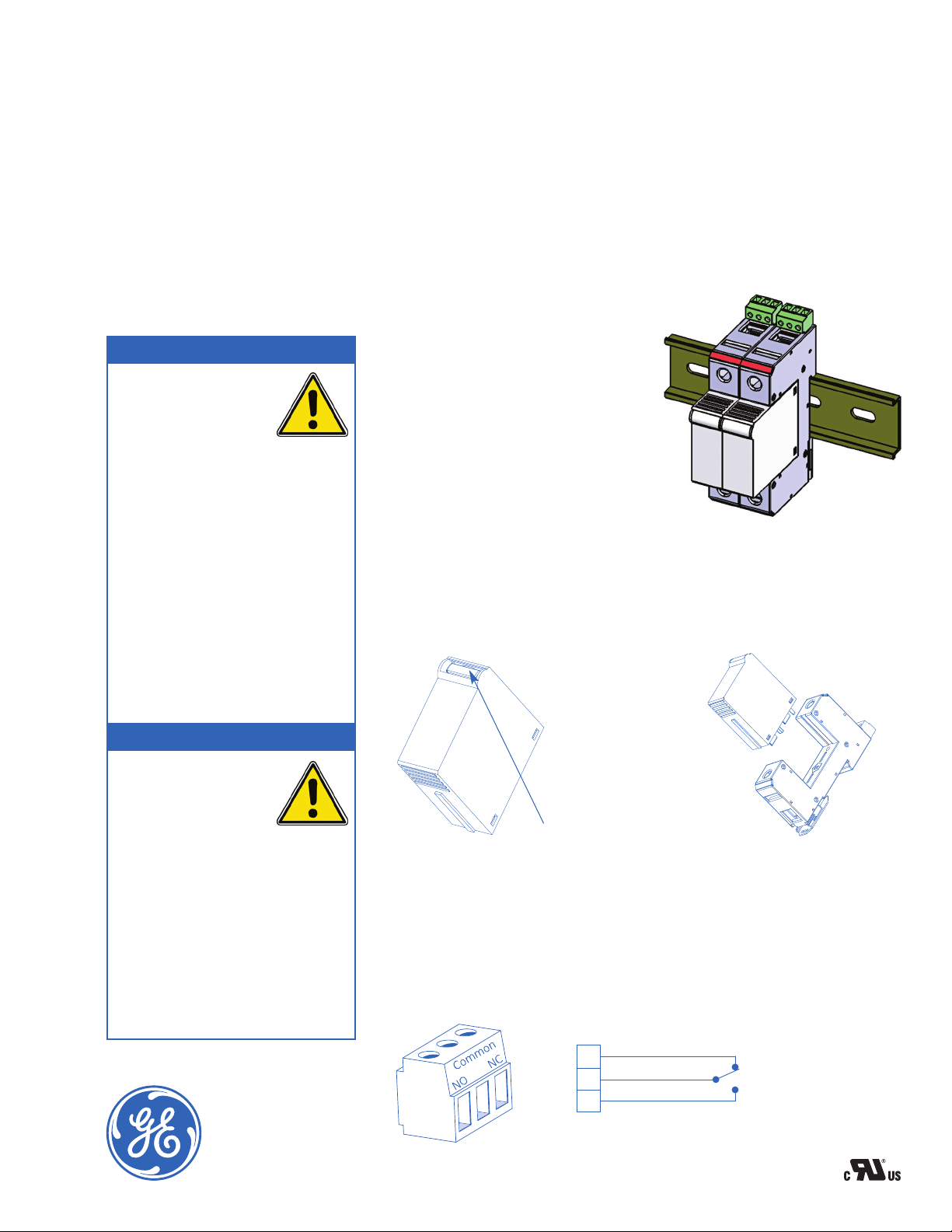
1. MOUNTING
Tranquell
™
SPD DIN Rail is designed to
mount onto a 35mm DIN rail or top-hat rail
(standard EN 50022, BS 5584) set in the
horizontal position. To install, first hook the
line side over a 35mm DIN rail and then push in
the load side until the spring loaded mounting
clip “clicks” onto the rail (See Figure 1).
3.
AUXILIARY MICROSWITCH INSTALLATION
Remote signaling is available on Tranquell
™
SPD DIN Rail products. #30 AWG to #16 AWG
(.051 mm
2
- 1.31 mm2) signal wire may be used. Maximum torque rating for the terminal
screw is 1.8 in.-lb. (0.113 N-m). The maximum continuous current rating for the microswitch contact is 3 amps. If applicable, install signal wiring as shown in Figure 3.
Figure 3 – Microswitch
NOTE:
Shown with no power applied
Field wiring by others
2. REPLACEMENT/REMOVAL
Replace the module if the RED indicator tab (See Figure 2) is visible
on any of the multiple pole units. To remove: (1) verify that you have the correct replacement
module; (2) disconnect power; (3) pull the pluggable module from the base; (4) push a new
pluggable module into the base. You will hear a “click”, indicating that the module is set
in place (See Figure 1). An insertion “key” built into the unit will help ensure that the module
has been correctly selected.
CAUTION: Use of excessive force, during insertion, can result
in damage to the module or the base.
Figure 2 – Visual Indicator Tab
Figure 1 –
Mounting
Contact between Common + NO
= Product Offline, Not-Protected
Contact between Common + NC
= Product Online, Protected
NC
Common
NO
Signal Wire Range: #30 AWG to #16 AWG (.051 mm2 - 1.31 mm2)
Terminal Torque: 1.8 in.-lb. (0.113 N-m)
Contact
Rating
125 VAC –
3 amp max.
-25°C to 85°C
Page 2
GE Digital Energy – Power Quality
830 W 40th Street, Chicago, IL 60609
USA
800 637 1738 www.gepowerquality.com
Information subject to change without notice. Please verify all details with
GE.
© 2010 General Electric Company All Rights Reserved
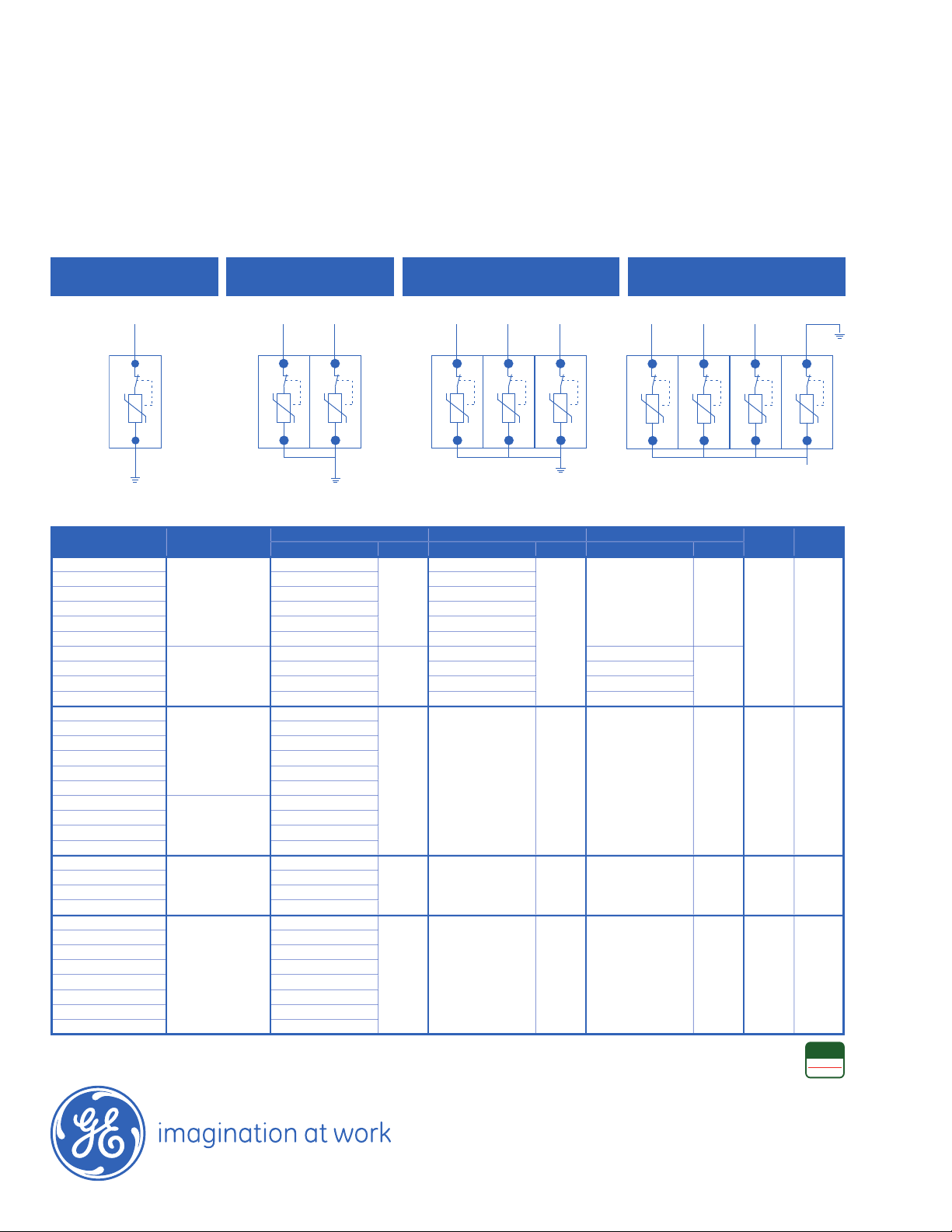
Figure 4 – Wiring Configuration Diagram (NOTE: Shown with no power applied)
NOTE: The Tranquell
™
DIN Rail SPD has been tested for safe operation without any
additional overcurrent protection, when correctly matched to the power system
parameters. A gG 160 Amp NH Fuse may be chosen to meet other requirements in
an
IEC application. Consult local codes and standards for appropriate fuse sizing.
SINGLE
PHASE
3 PHASE DELTA /
3 PHASE WYE, COMMON N/G
L1
L2
L3
N
G
3 PHASE HIGH LEG DELTA /
3 PHASE WYE, PLUS N-G
SPLIT
PHASE
Part Numbers & Specifications
4. WIRE INSTALLATION
#14
AWG to #6 AWG (2.08 mm
2
- 13.3 mm2), 60/75°C Copper
wire shall be used on phase and Neutral/
PE terminals.
Maximum torque to be applied to terminal screws is
14.75 in.-lb. (2.0 N-m). Strip back wire insulation 1/4" (6 mm).
Interconnecting wire should be kept at minimum length. Wire
bending radius should be >4" (100 mm). Do not loop or twist
interconnecting wire. Failure to meet these requirements may
result in higher let-through voltages.
Tranquell
™
SPD is normally installed in parallel with the load or
the electrical system wiring.
Determine electrical voltage configuration and proper modes
of protection and install wiring as shown in Figure 4.
Assembly System
Part Number
Wiring
Configuration
L-N/G Pluggable Module N - G Pluggable Module Hi-Leg Pluggable Module
No. of
Poles
No. of
Wires
Part Number Qty Part Number Qty Part Number Qty
TD120Y4025RMN
3 Phase Wye,
plug N-G
RU-180-25
3
RU-180-25
1
— —
4 5
TD120Y4050RMN RU-180-50 RU-180-50
TD277Y4025RMN RU-320-25 RU-180-25
TD277Y4050RMN RU-320-50 RU-180-50
TD347Y4025RMN RU-420-25 RU-275-25
TD347Y4050RMN RU-420-50 RU-275-50
TD240H4025RMN
3 Phase
High Leg Delta
RU-180-25
2
RU-180-25 RU-275-25
1
TD240H4050RMN RU-180-50 RU-180-50 RU-275-50
TD480H4025RMN RU-275-25 RU-180-25 RU-550-25
TD480H4050RMN RU-275-50 RU-180-50 RU-550-50
TD120Y3025RMP
3 Phase Wye
common N/G
RU-180-25
3 — — — — 3 4
TD120Y3050RMP RU-180-50
TD277Y3025RMP RU-320-25
TD277Y3050RMP RU-320-50
TD347Y3025RMP RU-420-25
TD347Y3050RMP RU-420-50
TD240D3025RMP
3 Phase Delta
RU-275-25
TD240D3050RMP RU-275-50
TD480D3025RMP RU-550-25
TD480D3050RMP RU-550-50
TD120S2025RMP
Split Phase
RU-180-25
2 — — — — 2 3
TD120S2050RMP RU-180-50
TD240S2025RMP RU-275-25
TD240S2050RMP RU-275-50
TD120S1025RMP
Single Phase
RU-180-25
1 — — — — 1 2
TD120S1050RMP RU-180-50
TD240S1025RMP RU-275-25
TD240S1050RMP RU-275-50
TD277S1025RMP RU-320-25
TD277S1050RMP RU-320-50
TD347S1025RMP RU-420-25
TD347S1050RMP RU-420-50
2020007801 (3/10)
L
G/N
L1
L2
G/N
L1
L2
L3
G/N
RoHS
COMPLIANT
2002/95/EC
 Loading...