


GE Digital Energy
Power Quality
GE Consumer & Industrial SA
General Electric Company
CH – 6595 Riazzino (Locarno)
Switzerland
T +41 (0)91 / 850 51 51
F +41 (0)91 / 850 52 52
www.gepowerquality.com
Installation Guide
Uninterruptible Power supply
SG Series 225 & 300
225 & 300 kVA / 480Vac UL / S2
imagination at work

Model:
SG Series 225 & 300 UL S2
Issued by Product Document Department – Riazzino - CH
Date of issue: 06/15/2010
File name: OPM_SGT_ISG_M22_M30_2US_V010
Revision: 1.0
Identification No.:
Up-dating
Revision Concerns Date
COPYRIGHT © 2010 by GE Consumer & Industrial SA
All rights reserved.
The information contained in this publication is intended solely for the purposes indicated.
The present publication and any other documentation supplied with the UPS system is not to be
reproduced, either in part or in its entirety, without the prior written consent of GE.
The illustrations and plans describing the equipment are intended as general reference only and are not
necessarily complete in every detail.
The content of this publication may be subject to modification without prior notice.
Modifications reserved Page 2/40
OPM_SGS_ISG_M22_M30_2US_V010.doc Installation Guide S G S er i e s 2 2 5 & 30 0 U L S2
Dear Customer,
We thank you for selecting our products and are
pleased to count you amongst our very valued
customers at GE.
We trust that the use of the SG Series 225 & 300
Uninterruptible Power Supply system, developed and
produced to the highest standards of quality, will give
you complete satisfaction.
Please read carefully the Installation Guide, which
contains all the necessary information and describes all
you need to know about the installation of the UPS.
Thank you for choosing GE !
START UP AND COMMISSIONING
A GE GLOBAL SERVICES FIELD ENGINEER must perform start-up and
commissioning of the UPS.
Please Contact GE. GLOBAL SERVICES at least two weeks prior to schedule
start-up and commissioning at 1-800-637-1738, or by E-mail at
pqservice@ge.com .
g
GE Consumer & Industrial SA
General Electric Company
CH – 6595 Riazzino (Locarno)
Switzerland
www.gepowerquality.com
Distributed in the USA by:
g
GE Digital Energy
Power Quality
2501 Pecan Street
Bonham, TX 75418
T: +1 800-637-1738
F: +1 903-640-0533
E: GEPQSales@ge.com
http://www.gedigitalenergy.com/ups
Your service contact:
Modifications reserved Page 3/40
OPM_SGS_ISG_M22_M30_2US_V010.doc Installation Guide S G S er i e s 2 2 5 & 30 0 U L S2
Preface
Congratulations on your choice of a SG Series Uninterruptible Power Supply (UPS).
It will help eliminate load disturbances due to unexpected power problem.
This manual describes how to prepare the installation site, and it provides weight and
dimensions and procedures for moving, installing and connecting the UPS.
Please refer to the Operating Manual, which describes the function of the UPS module, the
purpose and location of the switches, the meaning of the system events related to the
front panel indication, and provides procedures for starting and stopping the equipment.
While every care has been taken to ensure the completeness and accuracy of this manual,
GE assumes no responsibility or liability for any losses or damages resulting from the use
of the information contained in this document.
WARNING!
SG Series 225 & 300 is a product that needs to be installed by a licensed and
knowledgeable contractor.
We recommend that this manual be kept next to the UPS for future references.
If any problems are encountered with the procedures contained in this manual, please
contact your Service Center before you proceed.
This document shall not be copied or reproduced without the permission of GE.
Some of the information contained in this manual may be changed without notice to
reflect technical improvements.
Safety instructions
Read the safety instructions contained on the following pages carefully before the
installation of the UPS, options and battery system.
Pay attention to the rectangular boxes included in the text:
They contain important information and warning concerning electrical connections and
personnel safety.
Parallel version secured with RPA
When included in the text, this symbol refers to operation needed
only for parallel system.
Modifications reserved Page 4/40
OPM_SGS_ISG_M22_M30_2US_V010.doc Installation Guide S G S er i e s 2 2 5 & 30 0 U L S2

Table of contents Page
1 IMPORTANT SAFETY INSTRUCTIONS ........................................................................................................ 6
2 LAYOUT.......................................................................................................................................................... 9
2.1 LAYOUT SG Series 225 & 300 .......................................................................................................................................................9
3 INSTALLATION............................................................................................................................................ 10
3.1 TRANSPORT....................................................................................................................................................................................... 10
3.1.1 Dimensions and weight................................................................................................................................................................. 10
3.2 DELIVERY ............................................................................................................................................................................................11
3.3 STORAGE ............................................................................................................................................................................................11
3.3.1 Storage of the UPS .......................................................................................................................................................................... 11
3.3.2 Storage of battery........................................................................................................................................................................... 11
3.4 PLACE OF INSTALLATION ............................................................................................................................................................ 12
3.4.1 UPS location ....................................................................................................................................................................................... 12
3.4.2 Battery location................................................................................................................................................................................ 14
3.5 VENTILATION AND COOLING.....................................................................................................................................................15
3.6 UNPACKING ......................................................................................................................................................................................16
3.7 ELECTRICAL WIRING...................................................................................................................................................................... 17
3.7.1 Utility input connection................................................................................................................................................................. 17
3.7.2 Input/output over current protection and wire sizing..................................................................................................... 18
3.7.3 Battery over current protection and wire sizing................................................................................................................ 19
3.8 WIRING CONNECTION.................................................................................................................................................................. 21
3.8.1 Power connections.......................................................................................................................................................................... 21
3.8.2 Power connection with common input utility..................................................................................................................... 23
3.8.3 Power connection dual input utility (option)........................................................................................................................ 25
3.8.4 Battery and External Battery Breaker connection........................................................................................................... 28
3.8.5 Interface to External Bypass for single unit......................................................................................................................... 29
3.8.6 Connections to External Bypass switch in case of RPA Parallel System................................................................ 29
3.8.7 Setup for SG Series 225 & 300 intended to be operated in eBoost™ Operation Mode.................................... 30
3.9 RPA PARALLEL SYSTEM CONNECTION ..................................................................................................................................31
3.9.1 Power wiring of parallel units..................................................................................................................................................... 31
3.9.2 Parallel control bus connection................................................................................................................................................. 32
3.9.3 Control bus cable location........................................................................................................................................................... 34
4 CUSTOMER INTERFACE ............................................................................................................................. 36
4.1 CUSTOMER INTERFACE................................................................................................................................................................ 36
4.1.1 Serial Port J3 ...................................................................................................................................................................................... 37
4.1.2 Output free potential contacts .................................................................................................................................................. 37
4.1.3 Programmable input free contacts ......................................................................................................................................... 38
4.1.4 Gen Set Signaling (GEN ON)......................................................................................................................................................... 38
4.1.5 AUX external Maintenance Bypass ......................................................................................................................................... 38
4.1.6 Auxiliary Power Supply (APS) 24Vdc........................................................................................................................................ 38
4.1.7 EPO (Emergency Power Off) Input contact........................................................................................................................... 39
5 NOTES .......................................................................................................................................................... 40
5.1 NOTES FORM ....................................................................................................................................................................................40
Modifications reserved Page 5/40
OPM_SGS_ISG_M22_M30_2US_V010.doc Installation Guide S G S er i e s 2 2 5 & 30 0 U L S2

1 IMPORTANT SAFETY INSTRUCTIONS
SAVE THESE INSTRUCTIONS
This manual contains important instructions for models SG Series 225 & 300 that should be followed
during installation and maintenance of the UPS and battery.
- Move the UPS in an upright position in its original package to the final destination room.
To lift the cabinets, use a forklift or lifting belts with spreader bars.
- Check for sufficient floor and elevator loading capacity.
- Check the integrity of the UPS equipment carefully.
If you notice visible damage, do not install or start the UPS.
Contact the nearest Service Center immediately.
- WARNING! RISK OF ELECTRICAL SHOCK:
Do not remove covers, there are no user serviceable parts inside.
- After switching off takes 5 minutes for the DC capacitors to discharge because a lethally high voltage
remains at the terminals of the electrolytic capacitors.
- All maintenance and service work should be performed by qualified service personnel.
The UPS contains its own energy source (battery).
- The field-wiring outlets may be electrically live, even when the UPS is disconnected from the utility.
- Dangerous voltages may be present during battery operation.
- The battery must be disconnected during maintenance or service work.
- This UPS contains potentially hazardous voltages.
- Be aware that the inverter can restart automatically after the utility voltage is restored.
INSTALLATION
- This UPS must be installed and connected only by trained personnel.
- Verify accurately during Commissioning and Maintenance of the UPS, for the following:
Damaged components, squeezed wires and cables, or not correctly inserted plugs.
- After removing the sidewalls of the UPS, make sure that all earth connections when reassembling, are
correctly reattached.
- This UPS is intended for use in a controlled indoor environment free of conductive contaminants and
protected against animals intrusion.
- WARNING! HIGH EARTH LEAKAGE CURRENT:
Earth connection is essential before connecting to AC input!
- Switching OFF the unit does not isolate the UPS from the utility.
- Do not install the UPS in an excessively humid environment or near water.
- Avoid spilling liquids on or dropping any foreign object into the UPS.
- The unit must be placed in a sufficiently ventilated area; the ambient temperature should not exceed 104°F (40°C).
- Optimal battery life is obtained if the ambient temperature does not exceed 77°F (25°C).
- It is important that air can move freely around and through the unit. Do not block the air vents.
- Avoid locations in direct sunlight or near heat sources.
- Store the UPS in a dry location; storage temperature must be within -13°F (-25°C) to 131°F (+55°C).
- The optimal temperature for Battery storage is 68°F (20°C) to 77°F (25°C) and shall never exceed the range -
4°F (-20°C) to 104°F (40°C).
- If the unit is stored for a period exceeding 3 months, the battery must be recharged periodically (time
depending on storage temperature).
- The battery-voltage is dangerous for person’s safety.
- When replacing the battery, use the same cells number, voltage (V), capacity (Ah).
All the battery used, shall be of the same manufacturer and date of production.
- Proper disposal or recycling of the battery is required.
Refer to your local codes for disposal requirements.
- Never dispose of battery in a fire: they may explode.
- Do not open or mutilate battery: their contents (electrolyte) may be extremely toxic.
If exposed to electrolyte, wash immediately with plenty of water.
- Avoid charging in a sealed container.
- Never short-circuit the batteries.
When working with batteries, remove watches, rings or other metal objects, and only use insulated tools.
- In case of air shipment, the cables +/- going to the battery fuses/terminals shall be disconnected and isolated.
GENERAL
STORAGE
BATTERY
Modifications reserved Page 6/40
OPM_SGS_ISG_M22_M30_2US_V010.doc Installation Guide S G S er i e s 2 2 5 & 30 0 U L S2

Safety instructions when working with battery
EXTERNAL BATTERY MUST BE INSTALLED AND CONNECTED TO THE UPS BY
QUALIFIED SERVICE PERSONNEL ONLY.
INSTALLATION PERSONNEL MUST READ THIS ENTIRE SECTION BEFORE HANDLING
THE UPS AND BATTERY.
DANGER!
Full voltage and current are always present at the battery terminals.
The battery used in this system can provide dangerous voltages, extremely high currents and a
risk of electric shock.
If the terminals are shorted together or to ground they may cause severe injury.
You must be extremely careful to avoid electric shock and burns caused by contacting battery
terminals or shorting terminals during battery installation.
Do not touch uninsulated battery terminals.
A qualified service person, who is familiar with battery systems and required precautions, must
install and service the battery.
The installation must conform to national and local codes.
Keep unauthorized personnel away from the battery.
The qualified service person must take these precautions:
1 Wear protective clothing, such as rubber gloves and boots and protective eye wear
Batteries contain caustic acids and toxic materials and can rupture or leak if mistreated.
Remove rings and metal wristwatches or other metal objects and jewelry.
Do not carry metal objects in your pockets where the objects can fall into the battery
cabinet.
2 Tools must have insulated handles and must be insulated so that they will not short battery
terminals.
Do not allow a tool to short between individual or separate battery terminals or to the
cabinet or rack.
Do not lay tools or metal parts on top of the battery, and do not lay them where they could
fall onto the battery or into the cabinet.
3 Install the battery as shown on the drawing provided with the battery.
When connecting cables, never allow a cable to short across a battery’s terminals, the
string of battery, or to the cabinet or rack.
4 Align the cables on the battery terminals so that the cable lug will not contact any part of
the cabinet or rack, even if the battery is moved.
Keep the cable away from any sharp metal edges.
5 Install the battery cables in such a way that the UPS or battery cabinet doors cannot pinch them.
6 Do not connect the battery terminal to Ground.
If any battery terminal is inadvertently grounded, remove the source of the ground.
Contacting any part of a grounded battery can cause a risk of electric shock.
7 To reduce the risk of fire or electric shock, install the battery in a temperature and humidity
controlled indoor area, free of contaminants.
8 Battery system chassis ground (earth) must be connected to the UPS chassis ground (earth).
If you use conduits, this ground conductor must be routed in the same conduit as the
battery conductors.
9 Where conductors may be exposed to physical damage, protect the conductors in
accordance with all applicable codes.
10 If you are replacing the battery or repairing battery connections, shut OFF the UPS and
remove the battery fuses.
Modifications reserved Page 7/40
OPM_SGS_ISG_M22_M30_2US_V010.doc Installation Guide S G S er i e s 2 2 5 & 30 0 U L S2
Safety symbols and warnings
Safety warnings
The text of this manual contains some warnings to avoid risk to the persons and to avoid damages to
the UPS system and the supplied critical loads.
The non-observance of the warnings reminding hazardous situations could result in human injury and
equipment damages.
Please pay attention to the meaning of the following warnings and symbols.
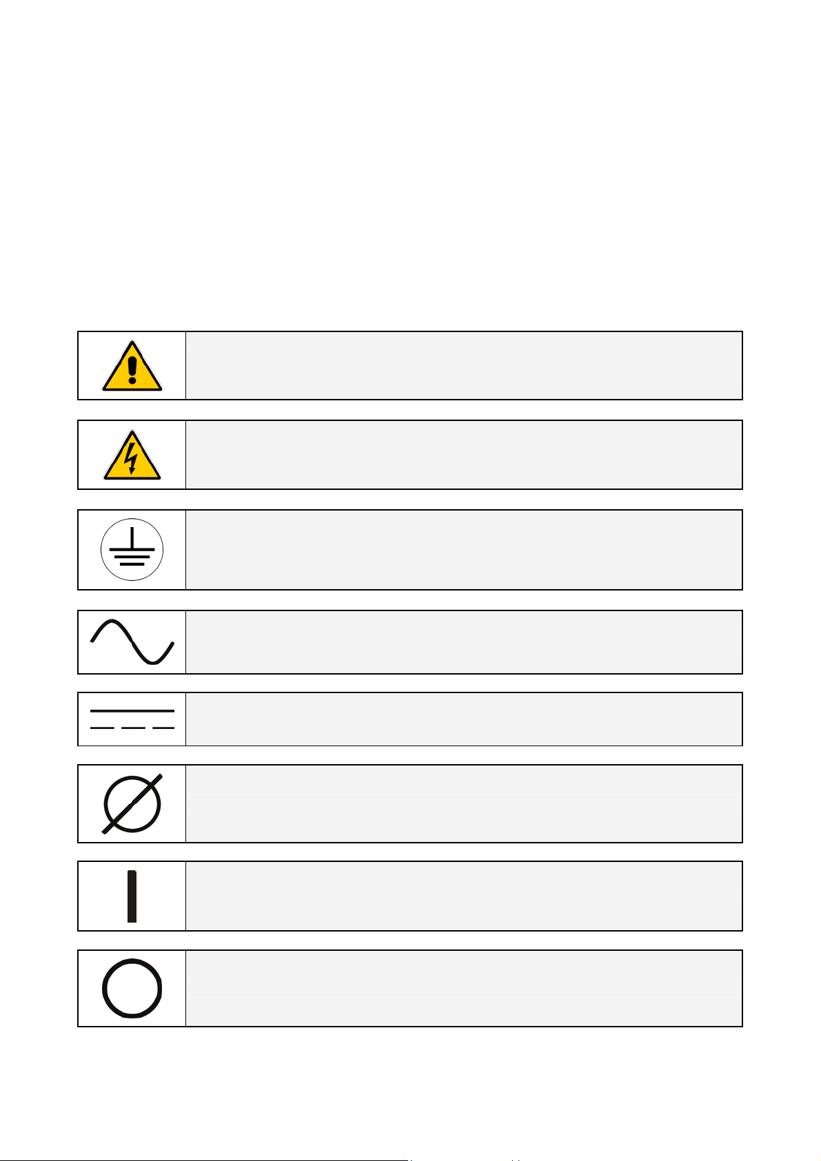
Throughout this manual the following symbols are defined:
WARNING, if instruction is not followed injury or serious equipment damage may
occur!
CAUTION, internal parts have dangerous voltage present.
Risk of electric shock!
PE (Earth) – GND (Ground)
PROTECTIVE GROUNDING TERMINAL:
A terminal which must be connected to earth ground prior to making any other
connection to the equipment.
A terminal to which or from which an alternating (sine wave) current or voltage
may be applied or supplied.
A terminal to which or from which a direct current or voltage may be applied or
supplied.
This symbol indicated the word “phase”.
This symbol indicates the principal on/off switch in the on position.
This symbol indicates the principal on/off switch in the off position.
Modifications reserved Page 8/40
OPM_SGS_ISG_M22_M30_2US_V010.doc Installation Guide S G S er i e s 2 2 5 & 30 0 U L S2

2 LAYOUT
2.1 LAYOUT SG Series 225 & 300
S
G
S
_
2
2
5
-
3
0
0
_
S
2
_
U
P
S
_
G
E
_
0
2
3
0
_
S
P
U
_
2
S
_
0
0
3
-
5
2
2
_
S
G
S
0
O
F
F
0
O
I ON
Q1
1
1
2
43
5
6
7
131298
14
10
15
11
2
171618
19
20
21
22
3
1
4
2
3
4
F
F
I ON
Q2
Fig. 2.1-1 SG Series 225 & 300 general view
4
0
_
S
P
U
_
2
S
_
0
0
3
-
5
2
2
_
S
G
S
0
O
F
F
0
O
I ON
Q1
1
1
2
3
4
5
6
12
7
13
98
14
21
22
15
16
2
17
18
19
20
10
11
3
1
4
2
3
4
F
F
Q2
I ON
CRXA XBPA
Fig. 2.1-3 SG Series 225 & 300 general view with optional 5
and removed protection panels
Fig. 2.1-2 SG Series 225 & 300 general view with open doors
1
1 Opening for top cable entry
(*)
2 Opening for bottom cable
entry
3 Compression lugs for Utility
input and Load output
4 Compression lugs for
4
3
external Battery
connection
CR Connectivity Rack
PA 24Vdc Auxiliary Power
Supply
XA Terminals for 24Vdc
Auxiliary Power Supply
connection
XB Terminals for EPO
connection
*) Remove this panel or
2
th
harmonic filter
provide means to capture
metal filings from cutting
conduit entry holes.
Modifications reserved Page 9/40
OPM_SGS_ISG_M22_M30_2US_V010.doc Installation Guide S G S er i e s 2 2 5 & 30 0 U L S2
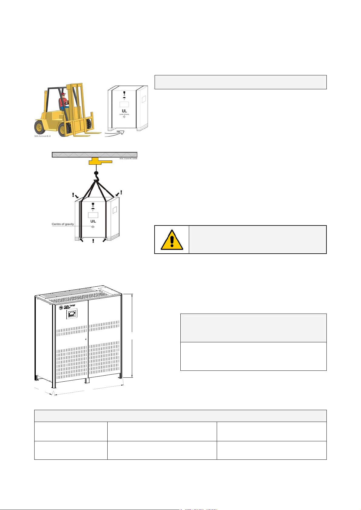
3 INSTALLATION
3.1 TRANSPORT
Forklift
Crane
Fig. 3.1-1 UPS cabinets moving
3.1.1 Dimensions and weight
S
U
1
0
_
E
G
_
s
n
o
i
s
n
e
m
i
d
S
P
U
_
2
S
_
0
0
3
-
5
2
2
_
S
G
S
Transport UPS only in upright position!
The UPS is packaged on a pallet suitable for handling with
a forklift.
Pay attention to the center of gravity.
The UPS must be moved in upright position.
Do not tilt cabinets more than +/- 10° during handling.
Move the UPS in it’s original package to the final
destination site.
Do not stack other packages on top: This could damage
the UPS.
If the UPS must be lifted by crane, use suitable lifting straps
and spreader bars.
Note of the center of gravity marked on the package.
Take all necessary precautions to avoid damage to the
cabinet while hoisting the UPS.
NOTE !
Check for sufficient floor and elevator
loading capacity.
Dimensions SG Series 225 & 300
H
(W x D x H)
64.96 x 31.50 x 70.90 inches
1,650 x 800 x 1,800 mm
D
Fig. 3.1.1-1 UPS cabinet dimensions
W
Weight SG Series 225 & 300
UPS rating
SG Series 225 & 300
P.S.: Weights including the 5th harmonic filter.
Modifications reserved Page 10/40
OPM_SGS_ISG_M22_M30_2US_V010.doc Installation Guide S G S er i e s 2 2 5 & 30 0 U L S2
Weight Floor loading
lbs/sq.ft - kg/m
3,087 / 1,400 218 / 1,061
2
lbs / kg

3.2 DELIVERY
When delivered, inspect the package integrity and the physical conditions of the cabinets carefully.
In case of any damage sustained during transport, immediately inform the carrier and contact your
local Service Center.
A detailed report of the damage is necessary for any insurance claim.
NOTE !
A DAMAGED UPS MUST NEVER BE INSTALLED OR CONNECTED TO UTILITY OR
BATTERY!
3.3 STORAGE
3.3.1 Storage of the UPS
The UPS is carefully packed for transport and storage so that it is in perfect condition when installed.
Never leave a UPS outside the building and don’t store other packages on the top of the UPS.
It is advisable to store the UPS in its original package in a dry, dust-free room, away from chemical
substances, and with a temperature range not exceeding -13°F (-25°C) to 131°F (55°C).
In case the battery is included please refer to Section 3.3.2.
Some important functions of the UPS, such as the customized functions, are defined by parameters
stored in a RAM memory.
A small backup battery located on the Control Unit board supplies the RAM.
If the storage time of the UPS exceeds 1 year, these functions should be verified by an authorized
Service Center before putting the UPS into operation.
3.3.2 Storage of battery
When the delivery includes a maintenance free battery, keep in mind that they are subject to selfdischarge and therefore you must recharge the battery.
The storage time without battery recharge depends on the temperature of the storage site.
The optimal temperature for Battery storage is 68°F (20°C) to 77°F (25°C) and shall never exceed the
range -4°F (-20°C) to 104°F (40°C).
Recharge stored maintenance free battery every:
6 months when the storage temperature is 68°F (20°C)
3 months when the storage temperature is 86°F (30°C)
2 months when the storage temperature is 95°F (35°C)
Modifications reserved Page 11/40
OPM_SGS_ISG_M22_M30_2US_V010.doc Installation Guide S G S er i e s 2 2 5 & 30 0 U L S2
3.4 PLACE OF INSTALLATION
3.4.1 UPS location
WARNING !
A QUALIFIED ELECTRICAL CONTRACTOR must carry out the installation and cabling
of the UPS.
If optional cabinets and accessories are included with the UPS, please refer to those
accompanying manuals for installation and operating instructions.
It is important to have a clean, dust-free environment provided with proper ventilation and airconditioning to keep the ambient temperature within the specified operating range.
The recommended air inlet temperature is from 68°F (20°C) to 77°F (25°C) (max. 104°F / 40°C).
Refer to Section 3.5.
Check for sufficient floor load capacity before installing the UPS and the Battery.
Refer to Section 3.1.1.
For Battery installation follow the local codes and the recommendation of the battery supplier.
NOTE !
Temperature is very important for valve-regulated batteries (maintenance free).
Operation at temperatures higher than 77°F (25°C) will reduce battery life.
The SG Series 225 & 300 UPS can radiate radio frequency energy.
Although some RFI filtering is inherent to the UPS there is no guarantee that the UPS will not influence
sensitive devices such as cameras and monitors that are positioned close by.
If interference is expected, the UPS should be moved away from the sensitive equipment.
A single-phase power outlet (120 Vac) should be provided near the UPS for connection of power tools,
test equipment or connectivity devices. This outlet must be grounded.
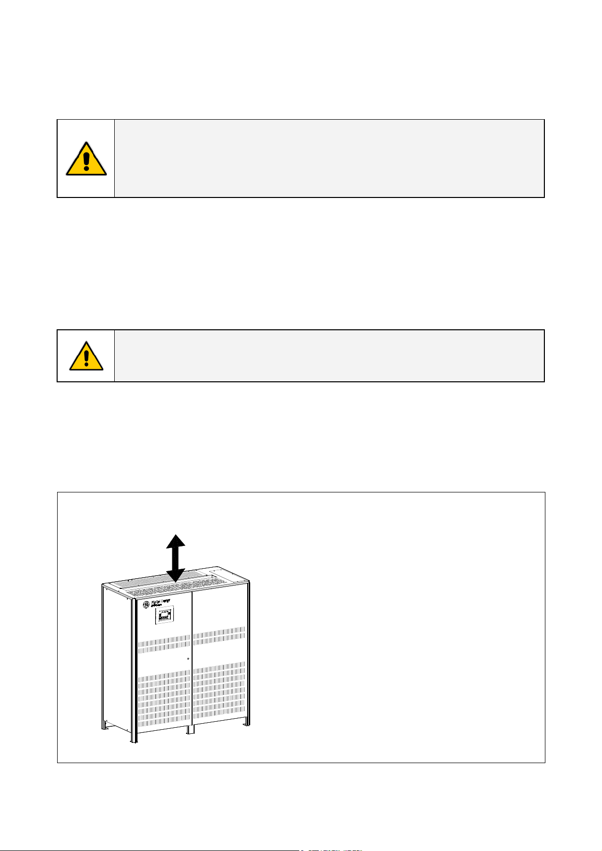
Positioning of the UPS SG Series 225 & 300
Min.
20" / 500mm
The rear panel of the UPS may be mounted flush
to a wall or other structure.
1
0
_
E
G
_
n
o
i
t
i
s
o
p
s
i
d
S
P
U
_
2
S
_
0
0
3
-
5
2
2
_
S
G
S
Clearance around the front of the unit should be
sufficient to enable free passage of personnel with
the doors fully open, and to allow sufficient airflow
to the door vents.
Check section 110-26(A) of the NEC code for
specific requirements.
Recommended minimum clearance between
ceiling and top of the UPS should be 20” (500 mm)
for proper cooling air exhaust.
In case of additional cabinets (external Batteries or
input, output transformers) these can be placed on
Fig. 3.4.1-1 SG Series 225 & 300 clearances
either side of the cabinet.
Modifications reserved Page 12/40
OPM_SGS_ISG_M22_M30_2US_V010.doc Installation Guide S G S er i e s 2 2 5 & 30 0 U L S2
 Loading...