

Page 1
g
GEK-90214B
GE Lift Truck
User’s Guide
144D2912G1
144D2933G1
144D2911G5
Page 2

GE LIFT TRUCK
EACH USER HAS THE RESPONSIBILITY TO
INSTRUCT ALL PERSONNEL ASSOCIATED
WITH THIS EQUIPMENT ON ALL SAFETY
PRECAUTIONS WHICH MUST BE OBSERVED.
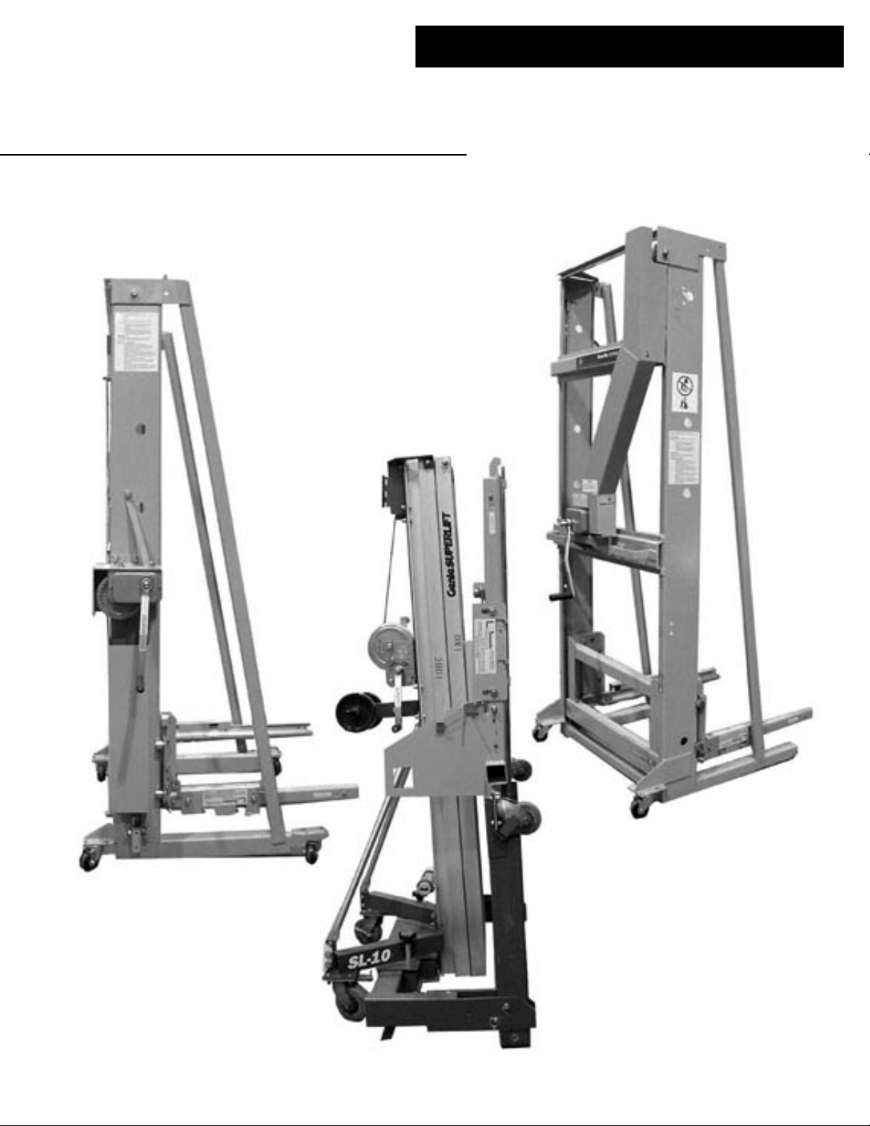
GENERAL
GE offers three styles of lift trucks for handling
Power/Vac circuit breakers, ground and test devices
and transformer and fuse rollouts. The first type is a
95” high double-mast truck (144D2933G1) that is compatible with indoor switchgear and outdoor non-aisle
switchgear. This truck has 2 fixed front wheels and 2
swivel rear wheels. The lifting winch is located on
the rear of the truck. The second style is a 87” high
double-mast truck (144D2912G1) that is compatible
with outdoor aisle switchgear. This truck has 4 swivel
wheels for easy turning in a confined space and has
the winch located on the right side. The third style is a
79” high single mast truck (144D2911G5) that is required for special indoor and outdoor applications.
The lift trucks are provided with interlocks to retain the device being handled and to lock the lift truck
to the switchgear while a device is being inserted or
removed. The carriage which lifts a device is raised or
lowered by means of a winch and cable. When the
winch handle is released the carriage is held in that
position by means of a clutch-brake internal to the
winch.
Two arms are attached to the carriage for engaging the track rollers on the sides of each device. The
following procedures describe the necessary steps to
remove a device from, or insert a device into, the
switchgear equipment. Be sure to read and understand
the safety rules identified in this manual before operating the lift truck.
The lift trucks are functional for both upper and
lower compartments provided the equipment is
mounted on no more than a three inch pad. See Table
2 - Lift Truck Selection (page 11).
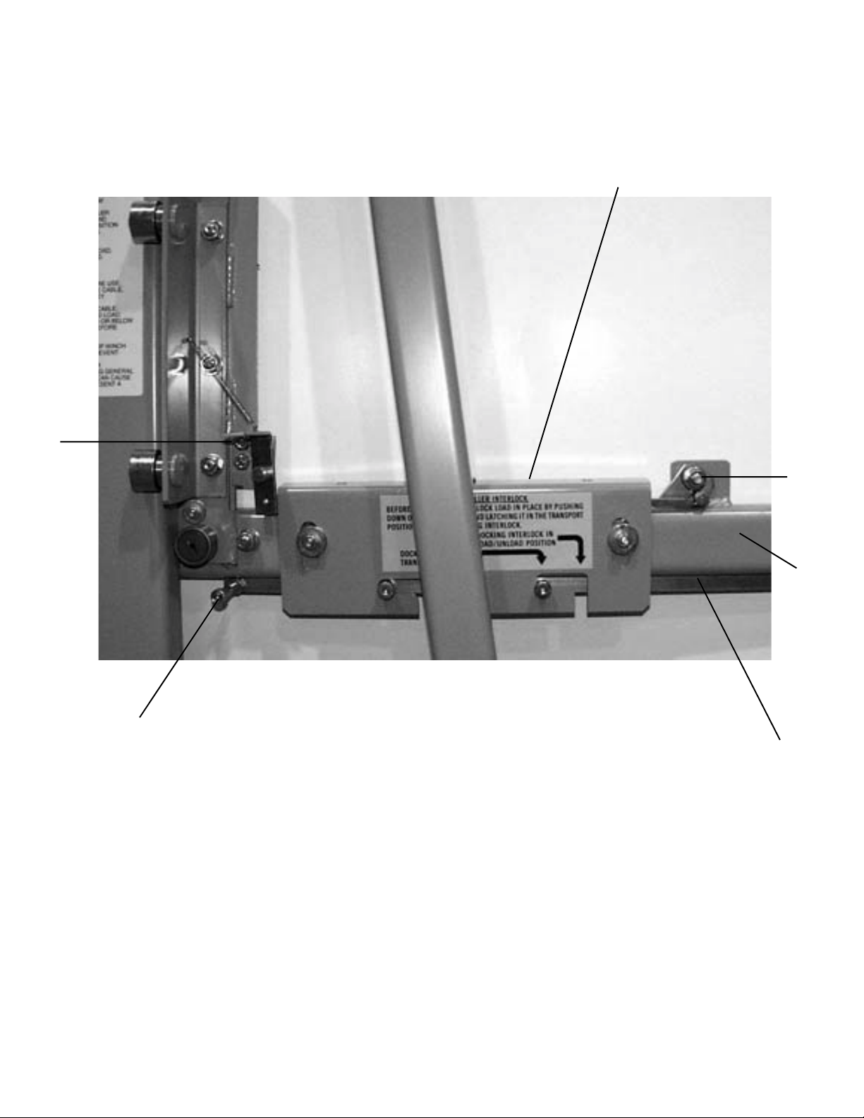
1. Prepare the truck for docking with the switchgear
equipment by making sure that both track roller
interlocks (1, Fig. 1) are in the “Transport” position (Fig. 2). If they are not, depress the track roller
interlocks and slide the docking interlocks (2, Fig.
1) all the way back toward the lift truck masts.
2. Adjust the height of the carriage until the docking
hooks at the ends of the arms are slightly higher
than the rail surface in the equipment. Position the
hooks over the slots in the rails and lower the
hooks into the slots. Place both track roller interlocks (1, Fig. 1) in the “Load/Unload” position (Fig.
3) by depressing them and sliding the docking interlocks (2, Fig. 1) forward, away from the lift truck
masts. The docking interlocks will extend under
the equipment rails and lock the truck arms to the
rails. The track roller interlocks are now in the
raised position so they are no longer blocking the
track rollers. Use the winch to adjust the lift truck’s
arms if they are not approximately level.
3. Release the device from the equipment and roll it
fully onto the lift truck rails until it comes in contact with the stops (3, Fig. 7) on the rails. The
catches that retain a device in the equipment compartment are different for the different devices so
see the instructions for the device being handled
for specific information. Verify that the device
rolled freely and that its rollers have properly engaged the rails. Place both track roller interlocks
(1, Fig. 1) in the “Transport” position (Fig. 2) by
depressing them and sliding the docking interlocks
(2, Fig. 1) all the way back toward the lift truck
masts. Raise the carriage slightly to release the
docking hooks from the slots in the equipment rail.
Pull the lift truck back to just clear the equipment
and lower the carriage to, or below, the maximum
transport position (Fig. 4) before transporting the
device to the desired location.
NOTE: The figures used in this instruction book depict
the 87” high double-mast lift truck. The operating
instructions apply to all three types
TO REMOVE A DEVICE FROM THE
SWITCHGEAR EQUIPMENT:
NOTE: To remove a breaker or instrument rollout from
an outdoor non-aisle switchgear lineup, first open the
outer door on the unit to the right of the one to be
worked on. Open this door to the fist stop location.
Then open the outer door of the unit to be worked on
to the second stop location. This will allow enough
room to access the right side lift truck track interlock.
2
4. To unload the device onto the floor, lower the carriage until the device is resting on the floor and
the load of the track rollers is no longer being supported by the lift truck arms. Place both track roller
interlocks (1, Fig. 1) in the “Load/Unload” position (Fig. 3) by depressing them and sliding the
docking interlocks (2, Fig. 1) forward, away from
the lift truck masts. The track roller interlocks are
now in their raised position. The lift truck can now
be pulled away from the device while holding the
backup track roller interlock handle (4, Fig. 1) in
the released position, away from the lift truck
masts.
Page 3

TO INSTALL A DEVICE INTO THE
SWITCHGEAR EQUIPMENT:
1. To load a device that is on the floor onto the lift
truck place both track roller interlocks (1, Fig. 1) in
the “Load/Unload” position (Fig. 3) by depressing
them and sliding the docking interlocks (2, Fig. 1)
forward, away from the lift truck masts. Adjust
the height of the arms so that they can engage the
track rollers on the sides of the device. Slight readjustments may be necessary as the arms approach
the rollers. It is also common to have to make
minor adjustments to allow the second set of track
rollers to be engaged. Move the lift truck forward,
or pull the device back, so that the device is all the
way towards the lift truck masts and the track rollers are in contact with the stops on the rails. Verify
that the device rolled freely and that all rollers have
properly engaged the rails.
5. To undock the lift truck from the equipment place
both track roller interlocks (1, Fig. 1) in the “Transport “ position (Fig. 2) by depressing them and
sliding the docking interlocks (2, Fig. 1) all the way
back toward the lift truck masts. Raise the carriage
slightly to release the docking hooks from the slots
in the equipment rail. Pull the lift truck back to clear
the equipment and lower the carriage to, or below, the maximum transport position (Fig. 4).
WARNING
As the load is lifted there should be a clicking noise
from the winch pawl. If this noise stops while a device
is being lifted, maintain a grip on the handle and lower
the load to the floor. Investigate why the pawl is not
engaging and make repairs before making any further
attempt to lift the load.
2. To lock the device onto the lift truck, place both
track roller interlocks (1, Fig. 1) into the “Transport” position (Fig. 2) by depressing them down
and sliding the docking interlocks (2, Fig. 1) all the
way back toward the lift truck masts.
3. Raise the carriage so the device is off the floor but
the carriage is at, or below, the maximum transport height before moving the device into position directly in front of the equipment compartment
into which the device is to be installed. The lift
truck should be as close to the equipment as possible, allowing just enough room for the device
and carriage to clear the equipment as it is being
raised. Adjust the height of the carriage until the
docking hooks at the ends of the arms are slightly
higher than the rail surface in the equipment. Position the hooks over the slots in the rails and lower
the hooks into the slots. Place both track roller interlocks (1, Fig. 1) in the “Load/Unload” position
(Fig. 3) by depressing them and sliding the docking interlocks (2, Fig. 1) forward, away from the
lift truck masts. The docking interlocks will extend
under the equipment rails and lock the truck arms
to the rails. The track roller interlocks are now in
the raised position so they are no longer blocking
the track rollers. Use the winch to adjust the lift
trucks’s arms if they are not approximately level.
4. Roll the device into the equipment while holding
the backup track roller interlock handle (4, Fig. 1)
in the released position, away from the lift truck
masts. Make sure that the device has engaged the
latches in the equipment (see the instructions for
the equipment and the device being used).
CAUTION
Although a backup to the track roller interlock is
functional for all but long wheel base devices such as
electrical ground & test devices and fuse rollouts, safe
use of this truck demands locking of both track roller
interlocks in the transport position before winch operation.
SAFETY RULES
1. Maximum load is 900 pounds.
2. Inspect lift truck daily before use. Items inspected
must include cable, cable fittings, pulleys, pulley
hardware and winch.
3. Replace damaged or frayed cable.
4. Stay out from under elevated load.
5. Lower lift truck carriage to or below maximum
transport height before transporting.
6. Use on smooth level surface only.
7. When lowering carriage, stop winch when cable
goes slack to prevent tangling.
8. The use of this lift truck for anything other than
handling GE Power/Vac devices can cause dam-
age to the lift truck and present a safety hazard.
The GE lift truck is included under the Occupation
Safety and Health Administration (OSHA) standard
1910.179 and should be inspected and tested per that
standard.
These instructions do not purport to cover all details or variations in equipment nor to provide for every possible
contingency to be met in connection with installation, operation or maintenance. Should further information be
desired or should particular problems arise which are not covered sufficiently for the purchaser’s purposes, the
matter should be referred to GE.
3
Page 4
1
4
5
6
3
2
Figure 1. Right Side Carriage Arm Assembly
1. Track Roller Interlock (right side)
2. Docking Interlock
3. Docking Interlock Handle
4. Backup Track Roller Interlock Handle
5. Backup Track Roller Interlock
6. Carriage Arm
4
Page 5

Figure 2. Track Roller and Docking Interlocks in Transport Position
Figure 3. Track Roller and Docking Interlocks in Load/Unload Position
5
Page 6

Figure 4. Maximum Transport Height
Table 1. Renewal Parts
Double Mast Single Mast
Lift Truck Lift Truck
144D2912G1/G2 144D2911G5
& 144D2933G1
Fig Item Description Part Number Part Number
1 1 Track Roller Interlock (Right Side) 0282A4397G004 0282A4397G004
5 1 Guide Roller 0282A3747P001
2 Guide Bracket (Right Side) 0282A4161G001
3 Backup Track Roller Interlock Spring 0282A3848P001 0282A3848P001
4 Backup Track roller Interlock 0209B4788G001 0209B4788G001
5 Carriage Roller 0282A4569P001
6 Winch 0282A3764G002
7 Cable (144D2912G1/G2 only) 0282A3575P001
(144D2933G1 only) 0346A9338P001
6 1 Track Roller Interlock (Left Side) 0282A4397G003 0282A4397G003
2 Guide Bracket (Left side) 0282A4161G002
3 Docking Interlock Handle N170P23040B6
4 Shoulder Bolts N94P38012B6 N94P3801B6
5 Docking Interlock 0282A4399P001 0209B5160P001
8 Left Arm 0209B4780G001 0144D2682G001
7 1 Carriage/Right Arm 0177C3744G001 0144D2682G002
2 Pulley 0282A4469P001
Bearing 0282A4556P001
Inner Race 0282A2000P055
3 Stop Block 0282A4349P001 0282A4349P001
4 Track Extrusions (Right Side) 0209B4774P001 0209B4774P001
Track Extrusions (Left Side) 0209B4774P001 0209B4774P002
- - Castor 0282A4555P001
- - Straight Wheel (0144D2912G2 only) 0282A4398P001
(144D2933G1 only) 0346A9338P001
6
Page 7

3
4
2
1
5
6
7
Figure 5. Right Side
1. Guide Bracket Roller
2. Right Side Guide Bracket
3. Backup Track Roller Interlock Return Spring
4. Backup Track Roller Interlock
5. Carriage Roller
6. Winch
7. Cable
7
Page 8

1
2
8
6
5
Figure 6. Left Side
1. Track Roller Interlock (Left Side)
2. Left Side Guide Bracket
3. Docking Interlock Handle
4. Shoulder Bolts
5. Docking Interlock
6. Arm Width Adjustment Access Hole
7. Arm Width Adjustment Nut (1 of 3)
8. Left Arm
3
4
7
8
Page 9

1
2
4
3
Figure 7. Carriage Inside
1.Carriage
2. Pulley
3. Stop Block
4. Track Extrusion
9
Page 10

CARRIAGE ARM ADJUSTMENTS
The arms are adjusted at the factory prior to shipping. Inspect carriage arm spacing if the device being
lifted does not fit on lift truck. The distance between the
two aluminum track extrusions (4, Fig. 7) should be 29.80
inches, plus 0.00, minus 0.03, and they should be vertically parallel within 0.125 inches.
On the double-masted lift truck the spacing between
the arms may be adjusted with three adjusting nuts (7,
Fig. 6), two of which must be reached through the access hole in the left mast (6, Fig. 6). The left arm may be
adjusted vertically parallel to the right arm by loosening the jam nut and turning the adjusting bolt located
underneath the left arm.
The arms are not adjustable vertically on the singlemasted lift truck, but they may be slid closer together or
farther apart. Enlarge the hole for the carriage arm spring
pin if more adjusting distance is required.
HANDLING OF ROLLOUTS:
It is possible that on some early fuse and transformer
rollouts the rear track rollers may extend about 1.5 inches
beyond the end of the lifting arms. Although the front
two sets of rollers engaged by the lifting arms provide
for safe lifting of the rollout, it may not be possible to
dock, or undock the lift truck because of interference between the rear rollers and the top of the front end of the
equipment track. The arms are prevented from being
lifted to release the docking hooks. If this occurs the following action may be required to allow removal of a
rollout.
Temporarily remove the stops on the lift truck arms
so that the rollout can enter the lifting arms farther. The
stops (3, Fig. 7) are rectangular plates on the inside of
the “C” shaped lifting arms (6, Fig. 1), held by a single
bolt. In many cases this will allow for rollout removal.
When reassembling, be sure to place the long end of the
part away from the mast. If rollout removal is not possible after this alteration, either of two options will allow removal of the rollout:
1. A 10 to 12 inch adjustable type wrench may be used
to slightly bend the top front corner of the equipment
rail up approximately 0.25 inch (see illustration be-
low).
2. Remove a piece from the top front of the equipment
rail so that the arm can be lifted to release the hook
without interfering with the top of the rail (see illus-
tration below). Care must be taken to prevent chips
from falling into the equipment.
On new rollouts the rear track rollers have been
moved forward 1.5 inches so they are fully engaged by
the lift truck arms and there is no interference with the
equipment rail.
10
Page 11

TT
able 2. Lift able 2. Lift
T
able 2. Lift
TT
able 2. Lift able 2. Lift
MODEL APPLICATIONS RESTRICTIONS FEATURES
144D2933G1 Indoor Switchgear Will not reach a roof mounted 95” High
Outdoor Weatherproof Switchgear Will not fit inside Outdoor Rear mounted winch
144D2912G1 Outdoor Aisle Switchgear Will not reach the top PT/CPT 87” High
144D2911G5 Roof mounted PT/CPT 79” High when collapsed
Outdoor Aisle Switchgear with Rear mounted winch
two PT/ CPT rollout trays in the Front & rear swivel wheels
upper “A” compartment. 76” Min. front aisle
Raised Switchgear Pads 950 Min. door swing*
TT
ruck Selectionruck Selection
T
ruck Selection
TT
ruck Selectionruck Selection
PT/CPT tray 76.5” Max. reach
Switchgear with an aisle Front fixed wheels
Rear swivel wheels
71” Min. front aisle
18” Min. side clearance
0
110
Min. door swing*
rollout tray when 2 are installed 69.5” Max. reach
in the upper “A” compartment Side mounted winch
Front & rear swivel wheels
58” Min. front aisle
18’ Min. left side clearance
30” Min. right side clearance
1100 Min. left side door swing*
1300 Min. right side door swing*
122.5” Max. reach
18” Min. side clearance
Collapsible for storage
*Note: The minimum door swing requirements are to allow operator access to the lift truck interlocks. If relays are on the door, then a 135
minimum door swing should be provided.
0
11
Page 12

g
GEK-90214B 1001
GE Industrial Systems
General Electric Company
510 East Agency
West Burlington, Iowa 52655
www.indsys.ge.com
 Loading...