

GE Healthcare
Corometrics™ 250cx Series Monitor
Operator’s Manual
Corometrics 250cx Series Monitor
English
2036946-001 C (paper)
© 2007 General Electric Company.
All Rights Reserved.

GE Healthcare
Corometrics™ 250cx Series Monitor
Operator’s Manual
Corometrics 250cx Series Monitor
English
2036946-001 C (paper)
© 2007 General Electric Company.
All Rights Reserved.

GUARANTEE
All equipment sold by GE Medical Systems Information Technologies, is fully guaranteed as to
materials and workmanship for a period of 1 year. GE Medical Systems Information
Technologies reserves the right to perform guarantee service operations in its own factory, at
an authorized repair station, or in the customer’s installation.
Our obligation under this guarantee is limited to repairing, or, at our option, replacing any
defective parts of our equipment, except fuses or batteries, without charge, if such defects
occur in normal service.
Claims for damage in shipment should be filed promptly with the transportation company. All
correspondence covering the instrument should specify the model and serial numbers.
GE MEDICAL SYSTEMS Information Technologies
A GE Healthcare Company
GE Medical Systems Information Technologies will make available on request such circuit diagrams, component
diagrams, component parts lists, descriptions, calibration instructions, or other information which will assist the users
or appropriately qualified technical personnel to repair those parts of the equipment which are classified by GE
Medical Systems Information Technologies as repairable. Refer to the 250/250cx Series Service Manual for further
information.
NOTE: In addition to software version 4.50, the information in this manual also applies to previous software
revisions of Corometrics 250cx Series Monitor. There are no user-apparent differences among these software
versions. Due to continuing product innovation, specifications in this manual are subject to change without notice.
NOTE: For technical documentation purposes, the abbreviation GE is used for the legal entity name, GE Medical
Systems Information Technologies
Ohmeda Oximetry and other trademarks (OxyTip+®, PIr™, TruSat™, TruSignal™, TruTrak+®, SuperSTAT™) are the
property of GE Medical Systems Information Technologies, a division of General Electric Corporation. All other product
and company names are the property of their respective owners.
MASIMO SET
®
is a trademark of Masimo Corporation. Possession or purchase of this device does not convey any
express or implied license to use the device with replacement parts which would, alone, or in combination with this
device, fall within the scope of one or more of the patents relating to the device.
NELLCOR
TAT-5000™, Exergen
®
, OxiMax®, C-LOCK® and SatSeconds™ are trademarks of Nellcor Puritan Bennett.
®
and TemporalScanner™ are trademarks of Exergen Corporation.
CAUTION: In the United States of America, Federal Law restricts this device to sale
by or on the order of a physician.
Corometrics and Marquette are registered trademarks of GE Medical Systems Information Technologies. GE is a
registered trademark of General Electric Company. All other product and brand names are trademarks or registered
trademarks of their respective companies. ©2005, 2006, 2007 GE Medical Systems Information Technologies. All rights
reserved. No part of this manual may be reproduced without the permission of GE Medical Systems Information
Technologies.
T-2 Corometrics 250cx Series Monitor Revision C
2036946-001 16-Sept-2007

CE Marking Information
CE Marking Information
Compliance
A GE brand Corometrics 250cx Series Monitor bears CE mark CE-0086
indicating its conformity with the provisions of the Council Directive 93/
42/EEC concerning medical devices and fulfills the essential
requirements of Annex I of this directive.
The device is manufactured in India; the CE mark is applied under the
authority of Notified Body BSI (0086).
The country of manufacture and appropriate Notified Body can be found
on the equipment labeling.
The product complies with the requirements of standard EN 60601-1-2
“Electromagnetic Compatibility—Medical Electrical Equipment” and
standard EN 60601-1 “General Requirements for Safety.”
0086
Components of the Certified Systems
The IEC electromagnetic compatibility (EN) standards require individual
equipment (components and accessories) to be configured as a system
for evaluation. For systems that include a number of different
equipments that perform a number of functions, one of each type of
equipment shall be included in the evaluation.
The equipment listed below is representative of all possible
combinations. For individual equipment certification, refer to the
appropriate declarations of conformity.
Component Description:
250cx Series Maternal/Fetal Monitor
Model 146 Fetal Acoustic Stimulator
Intrauterine Pressure Transducer
TOCO Transducer
FECG Cable/Legplate
Ultrasound Transducers (x2)
Blood Pressure Hose and Cuff
MSpO2 Interconnect Cable and Sensor
MECG Cable
FECG/MECG Adapter Cable
Remote Event Marker
RS-232C Interconnect Cables (x3)
Central Nurses Station Interconnect Cable
Model 2116B Keyboard and Interconnect Cable
Model 1563AAO Telemetry Cable
Exergen TemporalScanner
TM
TAT-5000 Assembly 2036641-001
Revision C 250cx Series Maternal/Fetal Monitor CE-1
2036946-001

Exceptions
CE Marking Information
The Monitor System EMC: Immunity Performance
None
Be aware that adding accessories or components, or modifying the
medical device or system may degrade the EMI performance. Consult
with qualified personnel regarding changes to the system configuration.
CE-2 250cx Series Maternal/Fetal Monitor Revision C
2036946-001

Contents
1 Safety . . . . . . . . . . . . . . . . . . . . . . . . . . . . . . . . . . . . . . . . . 1-1
General Information . . . . . . . . . . . . . . . . . . . . . . . . . . . . . . . . . . . . . . . . . . . . . . . . . . 1-3
General Use . . . . . . . . . . . . . . . . . . . . . . . . . . . . . . . . . . . . . . . . . . . . . . . . . . . . . .1-3
Responsibility of the Manufacturer . . . . . . . . . . . . . . . . . . . . . . . . . . . . . . . . . . . . .1-3
Responsibility of the User . . . . . . . . . . . . . . . . . . . . . . . . . . . . . . . . . . . . . . . . . . .1-3
Definitions of Terminology . . . . . . . . . . . . . . . . . . . . . . . . . . . . . . . . . . . . . . . . . . . . 1-4
Monitor Contraindications, Warnings, and Precautions . . . . . . . . . . . . . . . . . . . . 1-5
Warnings . . . . . . . . . . . . . . . . . . . . . . . . . . . . . . . . . . . . . . . . . . . . . . . . . . . . . . . .1-5
Cautions . . . . . . . . . . . . . . . . . . . . . . . . . . . . . . . . . . . . . . . . . . . . . . . . . . . . . . . . .1-8
Electromagnetic Interference . . . . . . . . . . . . . . . . . . . . . . . . . . . . . . . . . . . . . . . . .1-9
Equipment Symbols . . . . . . . . . . . . . . . . . . . . . . . . . . . . . . . . . . . . . . . . . . . . . . . . 1-10
2 Introduction . . . . . . . . . . . . . . . . . . . . . . . . . . . . . . . . . . . . 2-1
About the Manual . . . . . . . . . . . . . . . . . . . . . . . . . . . . . . . . . . . . . . . . . . . . . . . . . . . . 2-3
Purpose . . . . . . . . . . . . . . . . . . . . . . . . . . . . . . . . . . . . . . . . . . . . . . . . . . . . . . . . .2-3
Intended Audience . . . . . . . . . . . . . . . . . . . . . . . . . . . . . . . . . . . . . . . . . . . . . . . . .2-3
Illustrations . . . . . . . . . . . . . . . . . . . . . . . . . . . . . . . . . . . . . . . . . . . . . . . . . . . . . . .2-3
Fetal Monitoring Indications for Use . . . . . . . . . . . . . . . . . . . . . . . . . . . . . . . . . . . . 2-3
Surveillance . . . . . . . . . . . . . . . . . . . . . . . . . . . . . . . . . . . . . . . . . . . . . . . . . . . . . .2-3
Maternal Monitoring Indications for Use . . . . . . . . . . . . . . . . . . . . . . . . . . . . . . . . . 2-3
Blood Pressure . . . . . . . . . . . . . . . . . . . . . . . . . . . . . . . . . . . . . . . . . . . . . . .2-3
Pulse Oximetry . . . . . . . . . . . . . . . . . . . . . . . . . . . . . . . . . . . . . . . . . . . . . . . .2-4
Heart/Pulse Rate . . . . . . . . . . . . . . . . . . . . . . . . . . . . . . . . . . . . . . . . . . . . . .2-4
Series Overview . . . . . . . . . . . . . . . . . . . . . . . . . . . . . . . . . . . . . . . . . . . . . . . . . . . . . 2-4
The 250cx Series Monitor Features . . . . . . . . . . . . . . . . . . . . . . . . . . . . . . . . . . . .2-4
System Parameters (256cx and 259cx) . . . . . . . . . . . . . . . . . . . . . . . . . . . . .2-4
Fetal Parameters . . . . . . . . . . . . . . . . . . . . . . . . . . . . . . . . . . . . . . . . . . . . . .2-5
Maternal Parameters (259cx only) . . . . . . . . . . . . . . . . . . . . . . . . . . . . . . . . .2-6
Adding Fetal Movement Detection and/or Spectra Alerts . . . . . . . . . . . . . . . . . . .2-6
Revision C 250cx Series Maternal/Fetal Monitor i
2036946-001

3 Controls, Indicators, and Connectors . . . . . . . . . . . . . . . 3-1
Front Panel Description . . . . . . . . . . . . . . . . . . . . . . . . . . . . . . . . . . . . . . . . . . . . . . 3-3
Front Panel Displays . . . . . . . . . . . . . . . . . . . . . . . . . . . . . . . . . . . . . . . . . . . . . . . . . 3-6
Display Example . . . . . . . . . . . . . . . . . . . . . . . . . . . . . . . . . . . . . . . . . . . . . . . . . .3-7
Primary Labor Parameters . . . . . . . . . . . . . . . . . . . . . . . . . . . . . . . . . . . . . . . . . . . . 3-8
FHR Display . . . . . . . . . . . . . . . . . . . . . . . . . . . . . . . . . . . . . . . . . . . . . . . . . . . . . .3-8
UA Display . . . . . . . . . . . . . . . . . . . . . . . . . . . . . . . . . . . . . . . . . . . . . . . . . . . . . . . . . 3-9
Additional Parameters . . . . . . . . . . . . . . . . . . . . . . . . . . . . . . . . . . . . . . . . . . . . . . . 3-10
Maternal NIBP . . . . . . . . . . . . . . . . . . . . . . . . . . . . . . . . . . . . . . . . . . 3-10
MHR/P Area . . . . . . . . . . . . . . . . . . . . . . . . . . . . . . . . . . . . . . . . . . . . . . . . . . . . . . . 3-11
MSpO2 Area . . . . . . . . . . . . . . . . . . . . . . . . . . . . . . . . . . . . . . . . . . . . . . . . . . . . . . . 3-12
Waveform Area . . . . . . . . . . . . . . . . . . . . . . . . . . . . . . . . . . . . . . . . . . . . . . . . . .3-12
Time and Waveform Message Area . . . . . . . . . . . . . . . . . . . . . . . . . . . . . . . . . .3-12
Battery-Backed RAM Status . . . . . . . . . . . . . . . . . . . . . . . . . . . . . . . . . . . . . . . .3-13
Softkeys . . . . . . . . . . . . . . . . . . . . . . . . . . . . . . . . . . . . . . . . . . . . . . . . . . . . . . . . . . 3-13
Mode Title Softkeys . . . . . . . . . . . . . . . . . . . . . . . . . . . . . . . . . . . . . . . . . . . . . . .3-13
Waveform Softkeys . . . . . . . . . . . . . . . . . . . . . . . . . . . . . . . . . . . . . . . . . . . . . . .3-13
Dedicated Softkey Area . . . . . . . . . . . . . . . . . . . . . . . . . . . . . . . . . . . . . . . . . . . .3-14
Rear Panel Description . . . . . . . . . . . . . . . . . . . . . . . . . . . . . . . . . . . . . . . . . . . . . . 3-16
4 Setup Procedures . . . . . . . . . . . . . . . . . . . . . . . . . . . . . . . 4-1
Loading Strip Chart Recorder Paper . . . . . . . . . . . . . . . . . . . . . . . . . . . . . . . . . . . . 4-3
Power . . . . . . . . . . . . . . . . . . . . . . . . . . . . . . . . . . . . . . . . . . . . . . . . . . . . . . . . . . . . . 4-6
Interruption of Power . . . . . . . . . . . . . . . . . . . . . . . . . . . . . . . . . . . . . . . . . . . . . . .4-6
Self-Test Routine . . . . . . . . . . . . . . . . . . . . . . . . . . . . . . . . . . . . . . . . . . . . . . . . . . . . 4-7
Setup Screens . . . . . . . . . . . . . . . . . . . . . . . . . . . . . . . . . . . . . . . . . . . . . . . . . . . . . . 4-7
Using the Trim Knob Control . . . . . . . . . . . . . . . . . . . . . . . . . . . . . . . . . . . . . . . . .4-8
General Setup Screen . . . . . . . . . . . . . . . . . . . . . . . . . . . . . . . . . . . . . . . . . . . . . . . . 4-9
Play Song . . . . . . . . . . . . . . . . . . . . . . . . . . . . . . . . . . . . . . . . . . . . . . . . . . . . . . . .4-9
Song Volume . . . . . . . . . . . . . . . . . . . . . . . . . . . . . . . . . . . . . . . . . . . . . . . . . . . . .4-9
Temp Done Volume . . . . . . . . . . . . . . . . . . . . . . . . . . . . . . . . . . . . . . . . . . . . . . . .4-9
Brightness . . . . . . . . . . . . . . . . . . . . . . . . . . . . . . . . . . . . . . . . . . . . . . . . . . . . . . .4-9
Paper Speed . . . . . . . . . . . . . . . . . . . . . . . . . . . . . . . . . . . . . . . . . . . . . . . . . . . .4-10
Date . . . . . . . . . . . . . . . . . . . . . . . . . . . . . . . . . . . . . . . . . . . . . . . . . . . . . . . . . . .4-10
Time . . . . . . . . . . . . . . . . . . . . . . . . . . . . . . . . . . . . . . . . . . . . . . . . . . . . . . . . . . .4-10
MSpO2 Print Interval . . . . . . . . . . . . . . . . . . . . . . . . . . . . . . . . . . . . . . . . . . . . . .4-10
FSpO2 Print Interval . . . . . . . . . . . . . . . . . . . . . . . . . . . . . . . . . . . . . . . . . . . . . . .4-10
FSpO2 Trace . . . . . . . . . . . . . . . . . . . . . . . . . . . . . . . . . . . . . . . . . . . . . . . . . . . .4-10
Service . . . . . . . . . . . . . . . . . . . . . . . . . . . . . . . . . . . . . . . . . . . . . . . . . . . . . . . . .4-10
ii 250cx Series Maternal/Fetal Monitor Revision C
2036946-001

Preparing the Monitor for Patient Use . . . . . . . . . . . . . . . . . . . . . . . . . . . . . . . . . . 4-11
5 Fetal Heart Rate Monitoring . . . . . . . . . . . . . . . . . . . . . . . 5-1
Ultrasound (External Method) . . . . . . . . . . . . . . . . . . . . . . . . . . . . . . . . . . . . . . . . . . 5-3
Methodology . . . . . . . . . . . . . . . . . . . . . . . . . . . . . . . . . . . . . . . . . . . . . . . . . . . . .5-3
US/US2 Setup Screen . . . . . . . . . . . . . . . . . . . . . . . . . . . . . . . . . . . . . . . . . .5-3
Volume . . . . . . . . . . . . . . . . . . . . . . . . . . . . . . . . . . . . . . . . . . . . . . . . . . . . . . . . . .5-3
Alert . . . . . . . . . . . . . . . . . . . . . . . . . . . . . . . . . . . . . . . . . . . . . . . . . . . . . . . . . . . .5-4
Alarm Volume . . . . . . . . . . . . . . . . . . . . . . . . . . . . . . . . . . . . . . . . . . . . . . . . . . . .5-4
FECG (Internal Method) . . . . . . . . . . . . . . . . . . . . . . . . . . . . . . . . . . . . . . . . . . . . . . . 5-4
Methodology . . . . . . . . . . . . . . . . . . . . . . . . . . . . . . . . . . . . . . . . . . . . . . . . . . . . .5-4
Artifact Elimination . . . . . . . . . . . . . . . . . . . . . . . . . . . . . . . . . . . . . . . . . . . . . . . . .5-4
FECG Setup Screen . . . . . . . . . . . . . . . . . . . . . . . . . . . . . . . . . . . . . . . . . . . . . . . . . . 5-5
Volume . . . . . . . . . . . . . . . . . . . . . . . . . . . . . . . . . . . . . . . . . . . . . . . . . . . . . . . . . .5-5
Alarms . . . . . . . . . . . . . . . . . . . . . . . . . . . . . . . . . . . . . . . . . . . . . . . . . . . . . . . . . .5-5
Audio Alarms . . . . . . . . . . . . . . . . . . . . . . . . . . . . . . . . . . . . . . . . . . . . . . . . . . . . .5-5
Alarm Volume . . . . . . . . . . . . . . . . . . . . . . . . . . . . . . . . . . . . . . . . . . . . . . . . . . . .5-5
Fetal Heart Rate Alarms . . . . . . . . . . . . . . . . . . . . . . . . . . . . . . . . . . . . . . . . . . . . . . 5-6
FHR Threshold Alarms . . . . . . . . . . . . . . . . . . . . . . . . . . . . . . . . . . . . . . . . . . . . .5-6
FHR High Alarm . . . . . . . . . . . . . . . . . . . . . . . . . . . . . . . . . . . . . . . . . . . . . . .5-7
Sample Clinical Exceptions . . . . . . . . . . . . . . . . . . . . . . . . . . . . . . . . . . . . . .5-8
Active Signal Quality Alarm . . . . . . . . . . . . . . . . . . . . . . . . . . . . . . . . . . . . . .5-8
Resolved Signal Quality Alarm . . . . . . . . . . . . . . . . . . . . . . . . . . . . . . . . . . . .5-8
100% Signal Loss . . . . . . . . . . . . . . . . . . . . . . . . . . . . . . . . . . . . . . . . . . . . .5-9
Silencing an Audio Alarm . . . . . . . . . . . . . . . . . . . . . . . . . . . . . . . . . . . . . . . . . . . .5-9
Summary . . . . . . . . . . . . . . . . . . . . . . . . . . . . . . . . . . . . . . . . . . . . . . . . . . . . . . .5-10
Single Fetal Heart Rate Monitoring . . . . . . . . . . . . . . . . . . . . . . . . . . . . . . . . . . . . 5-10
Dual Fetal Heart Rate Monitoring . . . . . . . . . . . . . . . . . . . . . . . . . . . . . . . . . . . . . . 5-10
Heartbeat Coincidence . . . . . . . . . . . . . . . . . . . . . . . . . . . . . . . . . . . . . . . . . . . .5-11
Fetal Heart Rate Offset . . . . . . . . . . . . . . . . . . . . . . . . . . . . . . . . . . . . . . . . . . . .5-11
Activating the Fetal Heart Rate Offset Feature . . . . . . . . . . . . . . . . . . . . . .5-11
De-Activating the Fetal Heart Rate Offset Feature . . . . . . . . . . . . . . . . . . .5-12
6 Uterine Activity Monitoring . . . . . . . . . . . . . . . . . . . . . . . 6-1
Tocotransducer (External Method) . . . . . . . . . . . . . . . . . . . . . . . . . . . . . . . . . . . . . 6-3
Methodology . . . . . . . . . . . . . . . . . . . . . . . . . . . . . . . . . . . . . . . . . . . . . . . . . . . . .6-3
Establishing a Baseline . . . . . . . . . . . . . . . . . . . . . . . . . . . . . . . . . . . . . . . . . . . . .6-3
Initial Referencing . . . . . . . . . . . . . . . . . . . . . . . . . . . . . . . . . . . . . . . . . . . . .6-3
Accounting for Belt Tension . . . . . . . . . . . . . . . . . . . . . . . . . . . . . . . . . . . . . .6-4
More About Referencing . . . . . . . . . . . . . . . . . . . . . . . . . . . . . . . . . . . . . . . . . . . .6-4
Out of Range Condition . . . . . . . . . . . . . . . . . . . . . . . . . . . . . . . . . . . . . . . . .6-4
Manually Setting the Baseline at the Default Value . . . . . . . . . . . . . . . . . . . .6-4
Manually Overriding the Baseline Default Value . . . . . . . . . . . . . . . . . . . . . .6-4
Revision C 250cx Series Maternal/Fetal Monitor iii
2036946-001

Automatic Baseline “Zeroing” . . . . . . . . . . . . . . . . . . . . . . . . . . . . . . . . . . . . .6-4
Internal Method - Intrauterine Pressure (IUP) . . . . . . . . . . . . . . . . . . . . . . . . . . . . . 6-5
Methodology . . . . . . . . . . . . . . . . . . . . . . . . . . . . . . . . . . . . . . . . . . . . . . . . . . . . .6 -5
Why You Must Zero the System . . . . . . . . . . . . . . . . . . . . . . . . . . . . . . . . . . . . . .6-5
7 Maternal Heart/Pulse Rate Monitoring . . . . . . . . . . . . . . 7-1
MHR/P Source . . . . . . . . . . . . . . . . . . . . . . . . . . . . . . . . . . . . . . . . . . . . . . . . . . . . . . 7-3
MHR/P Setup Screen . . . . . . . . . . . . . . . . . . . . . . . . . . . . . . . . . . . . . . . . . . . . . . . . . 7-4
Source . . . . . . . . . . . . . . . . . . . . . . . . . . . . . . . . . . . . . . . . . . . . . . . . . . . . . . . . . .7-4
HR/PR Trace . . . . . . . . . . . . . . . . . . . . . . . . . . . . . . . . . . . . . . . . . . . . . . . . . . . . .7-5
Volume . . . . . . . . . . . . . . . . . . . . . . . . . . . . . . . . . . . . . . . . . . . . . . . . . . . . . . . . . .7-5
Alarms . . . . . . . . . . . . . . . . . . . . . . . . . . . . . . . . . . . . . . . . . . . . . . . . . . . . . . . . . .7-5
Alarm Volume . . . . . . . . . . . . . . . . . . . . . . . . . . . . . . . . . . . . . . . . . . . . . . . . . . . .7-5
MECG Lead . . . . . . . . . . . . . . . . . . . . . . . . . . . . . . . . . . . . . . . . . . . . . . . . . . . . . .7-5
MECG Pacer . . . . . . . . . . . . . . . . . . . . . . . . . . . . . . . . . . . . . . . . . . . . . . . . . . . . .7-6
Maternal ECG Monitoring . . . . . . . . . . . . . . . . . . . . . . . . . . . . . . . . . . . . . . . . . . . . . 7-7
Theory and Methodology . . . . . . . . . . . . . . . . . . . . . . . . . . . . . . . . . . . . . . . . . . . .7-7
Pacemaker Safety Information . . . . . . . . . . . . . . . . . . . . . . . . . . . . . . . . . . . . . . . .7-7
MECG Waveform . . . . . . . . . . . . . . . . . . . . . . . . . . . . . . . . . . . . . . . . . . . . . . . . . .7-8
8 Maternal Non-Invasive Blood Pressure Monitoring . . . . 8-1
Blood Pressure Safety Precautions . . . . . . . . . . . . . . . . . . . . . . . . . . . . . . . . . . . . . 8-3
Warnings . . . . . . . . . . . . . . . . . . . . . . . . . . . . . . . . . . . . . . . . . . . . . . . . . . . . . . . . . . 8-4
NIBP Determination . . . . . . . . . . . . . . . . . . . . . . . . . . . . . . . . . . . . . . . . . . . . . . . . . . 8-5
SuperSTAT NIBP Determination . . . . . . . . . . . . . . . . . . . . . . . . . . . . . . . . . . . . . . . 8-5
Accelerated Determination . . . . . . . . . . . . . . . . . . . . . . . . . . . . . . . . . . . . . . .8-6
Systolic Search . . . . . . . . . . . . . . . . . . . . . . . . . . . . . . . . . . . . . . . . . . . . . . . . . . .8-6
NIBP Setup Screen . . . . . . . . . . . . . . . . . . . . . . . . . . . . . . . . . . . . . . . . . . . . . . . . . . 8-7
Mode . . . . . . . . . . . . . . . . . . . . . . . . . . . . . . . . . . . . . . . . . . . . . . . . . . . . . . . . . . .8-7
Target . . . . . . . . . . . . . . . . . . . . . . . . . . . . . . . . . . . . . . . . . . . . . . . . . . . . . . . . . . .8-7
NIBP Done Volume . . . . . . . . . . . . . . . . . . . . . . . . . . . . . . . . . . . . . . . . . . . . . . . .8-8
Alarms . . . . . . . . . . . . . . . . . . . . . . . . . . . . . . . . . . . . . . . . . . . . . . . . . . . . . . . . . .8-8
Alarm Volume . . . . . . . . . . . . . . . . . . . . . . . . . . . . . . . . . . . . . . . . . . . . . . . . . . . .8-8
NIBP Monitoring . . . . . . . . . . . . . . . . . . . . . . . . . . . . . . . . . . . . . . . . . . . . . . . . . . . . . 8-8
Checklist . . . . . . . . . . . . . . . . . . . . . . . . . . . . . . . . . . . . . . . . . . . . . . . . . . . . . . . .8 -8
Patient Preparation . . . . . . . . . . . . . . . . . . . . . . . . . . . . . . . . . . . . . . . . . . . . . . . .8-8
Blood Pressure Methodology . . . . . . . . . . . . . . . . . . . . . . . . . . . . . . . . . . . . . . . . .8-9
Hydrostatic Effect . . . . . . . . . . . . . . . . . . . . . . . . . . . . . . . . . . . . . . . . . . . . . . . . .8-10
Manual Mode . . . . . . . . . . . . . . . . . . . . . . . . . . . . . . . . . . . . . . . . . . . . . . . . . . . .8-10
Automatic Mode . . . . . . . . . . . . . . . . . . . . . . . . . . . . . . . . . . . . . . . . . . . . . . . . . .8-10
Taking a Manual Reading Between Auto Determinations . . . . . . . . . . . . . .8-11
iv 250cx Series Maternal/Fetal Monitor Revision C
2036946-001

Venous Return in Auto Mode . . . . . . . . . . . . . . . . . . . . . . . . . . . . . . . . . . . .8-11
Adjusting the Interval Time Between Automatic Determinations . . . . . . . . .8-11
NIBP Interval Button Shortcut . . . . . . . . . . . . . . . . . . . . . . . . . . . . . . . . . . .8-12
Terminating a Determination in Progress . . . . . . . . . . . . . . . . . . . . . . . . . . . . . .8-13
Smart BP Feature . . . . . . . . . . . . . . . . . . . . . . . . . . . . . . . . . . . . . . . . . . . . . . . . . . . 8-13
Enabling/Disabling Smart BP . . . . . . . . . . . . . . . . . . . . . . . . . . . . . . . . . . . . . . . .8-13
Methodology . . . . . . . . . . . . . . . . . . . . . . . . . . . . . . . . . . . . . . . . . . . . . . . . . . . .8-13
9 Maternal Pulse Oximetry Monitoring . . . . . . . . . . . . . . . . 9-1
MSpO2 Technology . . . . . . . . . . . . . . . . . . . . . . . . . . . . . . . . . . . . . . . . . . . . . . . . . . 9-3
Which Module is Installed? . . . . . . . . . . . . . . . . . . . . . . . . . . . . . . . . . . . . . . . . . .9-3
Theory of Operation . . . . . . . . . . . . . . . . . . . . . . . . . . . . . . . . . . . . . . . . . . . . . . . .9-4
Ohmeda TruSignal™ Oximetry . . . . . . . . . . . . . . . . . . . . . . . . . . . . . . . . . . .9-4
TruSignal™ Enhanced SpO2 . . . . . . . . . . . . . . . . . . . . . . . . . . . . . . . . 9-4
Signal processing . . . . . . . . . . . . . . . . . . . . . . . . . . . . . . . . . . . . . . . . . 9-4
Masimo SET® . . . . . . . . . . . . . . . . . . . . . . . . . . . . . . . . . . . . . . . . . . . . . . . .9-4
Signal Processing . . . . . . . . . . . . . . . . . . . . . . . . . . . . . . . . . . . . . . . . 9-4
Nellcor OxiMax® . . . . . . . . . . . . . . . . . . . . . . . . . . . . . . . . . . . . . . . . . . . . . .9-5
Automatic Calibration . . . . . . . . . . . . . . . . . . . . . . . . . . . . . . . . . . . . . . 9-6
SatSeconds™ . . . . . . . . . . . . . . . . . . . . . . . . . . . . . . . . . . . . . . . . . . . 9-6
SatSeconds “Safety Net” . . . . . . . . . . . . . . . . . . . . . . . . . . . . . . . . . . . 9-8
Using SatSeconds . . . . . . . . . . . . . . . . . . . . . . . . . . . . . . . . . . . . . . . . 9-8
MSpO2 Setup Screen . . . . . . . . . . . . . . . . . . . . . . . . . . . . . . . . . . . . . . . . . . . . . . . . . 9-9
Response Time (Nellcor 506 Technology Only) . . . . . . . . . . . . . . . . . . . . . . . . . .9-9
Response Time (Nellcor NELL-3 Technology Only) . . . . . . . . . . . . . . . . . . . . . . .9-9
Sensitivity (Masimo Technology Only) . . . . . . . . . . . . . . . . . . . . . . . . . . . . . . . . . .9-9
Averaging Time (Masimo Technology Only) . . . . . . . . . . . . . . . . . . . . . . . . . . . .9-10
Print Interval . . . . . . . . . . . . . . . . . . . . . . . . . . . . . . . . . . . . . . . . . . . . . . . . . . . . .9-10
%O2 Trace . . . . . . . . . . . . . . . . . . . . . . . . . . . . . . . . . . . . . . . . . . . . . . . . . . . . . .9-10
Alarms . . . . . . . . . . . . . . . . . . . . . . . . . . . . . . . . . . . . . . . . . . . . . . . . . . . . . . . . .9-10
Alarm Volume . . . . . . . . . . . . . . . . . . . . . . . . . . . . . . . . . . . . . . . . . . . . . . . . . . .9-10
MSpO2 Methodology . . . . . . . . . . . . . . . . . . . . . . . . . . . . . . . . . . . . . . . . . . . . . . . . 9-10
MSpO2 Pulse Beat Audio . . . . . . . . . . . . . . . . . . . . . . . . . . . . . . . . . . . . . . . . . . .9-11
The MSpO2 Waveform . . . . . . . . . . . . . . . . . . . . . . . . . . . . . . . . . . . . . . . . . . . . .9-11
Module and Probe Compatibility . . . . . . . . . . . . . . . . . . . . . . . . . . . . . . . . . . . . . . 9-11
Modules and Sensors . . . . . . . . . . . . . . . . . . . . . . . . . . . . . . . . . . . . . . . . . . . . .9-12
No Implied License . . . . . . . . . . . . . . . . . . . . . . . . . . . . . . . . . . . . . . . . . . . . . . .9-12
Sensors . . . . . . . . . . . . . . . . . . . . . . . . . . . . . . . . . . . . . . . . . . . . . . . 9-12
10 Alarms . . . . . . . . . . . . . . . . . . . . . . . . . . . . . . . . . . . . . . . 10-1
Introduction . . . . . . . . . . . . . . . . . . . . . . . . . . . . . . . . . . . . . . . . . . . . . . . . . . . . . . . 10-3
Alarm Setup . . . . . . . . . . . . . . . . . . . . . . . . . . . . . . . . . . . . . . . . . . . . . . . . . . . . . . . 10-3
Master Alarm Setup Screen . . . . . . . . . . . . . . . . . . . . . . . . . . . . . . . . . . . . . . . . .10-3
Revision C 250cx Series Maternal/Fetal Monitor v
2036946-001

Alarms . . . . . . . . . . . . . . . . . . . . . . . . . . . . . . . . . . . . . . . . . . . . . . . . . . . . .10-3
Alarm Volume . . . . . . . . . . . . . . . . . . . . . . . . . . . . . . . . . . . . . . . . . . . . . . .10-4
Alarm Silence . . . . . . . . . . . . . . . . . . . . . . . . . . . . . . . . . . . . . . . . . . . . . . . .10-4
Alarm Setting Indicators . . . . . . . . . . . . . . . . . . . . . . . . . . . . . . . . . . . . . . . . . . . .10-5
Maternal Alarm Occurring During Setup . . . . . . . . . . . . . . . . . . . . . . . . . . . . . . .10-5
Alarm Behavior . . . . . . . . . . . . . . . . . . . . . . . . . . . . . . . . . . . . . . . . . . . . . .10-5
Fetal Heart Rate Alarms . . . . . . . . . . . . . . . . . . . . . . . . . . . . . . . . . . . . . . . . . . . . . 10-6
FHR Patient Alarms . . . . . . . . . . . . . . . . . . . . . . . . . . . . . . . . . . . . . . . . . . . . . . .10-6
Active Patient Alarm . . . . . . . . . . . . . . . . . . . . . . . . . . . . . . . . . . . . . . . . . . .10-6
Resolved Patient Alarm . . . . . . . . . . . . . . . . . . . . . . . . . . . . . . . . . . . . . . . .10-6
FHR Signal Quality Alarms . . . . . . . . . . . . . . . . . . . . . . . . . . . . . . . . . . . . . . . . .10-6
Active Signal Quality Alarm . . . . . . . . . . . . . . . . . . . . . . . . . . . . . . . . . . . . .10-6
Resolved Signal Quality Alarm . . . . . . . . . . . . . . . . . . . . . . . . . . . . . . . . . .10-7
Silencing an FHR Audio Alarm . . . . . . . . . . . . . . . . . . . . . . . . . . . . . . . . . . . . . .10-7
Maternal Alarms . . . . . . . . . . . . . . . . . . . . . . . . . . . . . . . . . . . . . . . . . . . . . . . . . . . . 10-7
Maternal Patient Alarms . . . . . . . . . . . . . . . . . . . . . . . . . . . . . . . . . . . . . . . . . . . .10-7
Active Patient Alarm . . . . . . . . . . . . . . . . . . . . . . . . . . . . . . . . . . . . . . . . . . .10-7
Resolved Patient Alarm . . . . . . . . . . . . . . . . . . . . . . . . . . . . . . . . . . . . . . . .10-7
Signal Quality Alarms . . . . . . . . . . . . . . . . . . . . . . . . . . . . . . . . . . . . . . . . . . . . . .10-7
Active Signal Quality Alarm . . . . . . . . . . . . . . . . . . . . . . . . . . . . . . . . . . . . .10-8
Resolved Signal Quality Alarm . . . . . . . . . . . . . . . . . . . . . . . . . . . . . . . . . .10-8
Silencing a Maternal Audio Alarm . . . . . . . . . . . . . . . . . . . . . . . . . . . . . . . . . . . .10-8
Alarms Summary . . . . . . . . . . . . . . . . . . . . . . . . . . . . . . . . . . . . . . . . . . . . . . . . . . . 10-9
11 Recorder Modes . . . . . . . . . . . . . . . . . . . . . . . . . . . . . . . 11-1
Modes . . . . . . . . . . . . . . . . . . . . . . . . . . . . . . . . . . . . . . . . . . . . . . . . . . . . . . . . . . . . 11-3
Off Mode . . . . . . . . . . . . . . . . . . . . . . . . . . . . . . . . . . . . . . . . . . . . . . . . . . . . . . . . . . 11-3
On Mode . . . . . . . . . . . . . . . . . . . . . . . . . . . . . . . . . . . . . . . . . . . . . . . . . . . . . . . . . . 11-3
Maternal-Only Mode . . . . . . . . . . . . . . . . . . . . . . . . . . . . . . . . . . . . . . . . . . . . . . . . 11-3
What is the Maternal-Only Mode? . . . . . . . . . . . . . . . . . . . . . . . . . . . . . . . . . . . .11-3
Printing Style . . . . . . . . . . . . . . . . . . . . . . . . . . . . . . . . . . . . . . . . . . . . . . . . . . . .11-3
Changing Recorder Modes . . . . . . . . . . . . . . . . . . . . . . . . . . . . . . . . . . . . . . . . . . . 11-4
Functionality with a QS System . . . . . . . . . . . . . . . . . . . . . . . . . . . . . . . . . . . . . . . 11-5
Paper Versus Electronic Strip Charts . . . . . . . . . . . . . . . . . . . . . . . . . . . . . . . . .11-5
Fetal Heart Rate Alarms . . . . . . . . . . . . . . . . . . . . . . . . . . . . . . . . . . . . . . . . . . .11-6
Trends . . . . . . . . . . . . . . . . . . . . . . . . . . . . . . . . . . . . . . . . . . . . . . . . . . . . . . . . . . . . 11-6
Multiple Trends . . . . . . . . . . . . . . . . . . . . . . . . . . . . . . . . . . . . . . . . . . . . . . . . . .11-6
SpO2 Scale . . . . . . . . . . . . . . . . . . . . . . . . . . . . . . . . . . . . . . . . . . . . . . . . . . . . . .11-7
Annotations . . . . . . . . . . . . . . . . . . . . . . . . . . . . . . . . . . . . . . . . . . . . . . . . . . . . . . . 11-7
Standard Annotations . . . . . . . . . . . . . . . . . . . . . . . . . . . . . . . . . . . . . . . . . . . . .11-8
Blood Pressure Annotations . . . . . . . . . . . . . . . . . . . . . . . . . . . . . . . . . . . . . . . .11-8
Maternal Pulse Oximetry Annotations . . . . . . . . . . . . . . . . . . . . . . . . . . . . . . . . .11-9
vi 250cx Series Maternal/Fetal Monitor Revision C
2036946-001

Annotations from a Central Information System . . . . . . . . . . . . . . . . . . . . . . . . .11-9
Multiple Annotations . . . . . . . . . . . . . . . . . . . . . . . . . . . . . . . . . . . . . . . . . . . . . . .11-9
Summary of Annotations . . . . . . . . . . . . . . . . . . . . . . . . . . . . . . . . . . . . . . . . . . . 11-10
Adjustable Recorder Font Size . . . . . . . . . . . . . . . . . . . . . . . . . . . . . . . . . . . . . . . 11-13
Chart Style Vital Signs Printing . . . . . . . . . . . . . . . . . . . . . . . . . . . . . . . . . . . . . . 11-14
Enabling/Disabling Chart-Style Printing . . . . . . . . . . . . . . . . . . . . . . . . . . . . . . .11-14
Examples of Printing Styles . . . . . . . . . . . . . . . . . . . . . . . . . . . . . . . . . . . . . . . .11-15
Chart-Style Printing Examples . . . . . . . . . . . . . . . . . . . . . . . . . . . . . . . . . .11-15
Real-Time Printing Example . . . . . . . . . . . . . . . . . . . . . . . . . . . . . . . . . . .11-15
Chart-Style 7-Minute Exception for NIBP . . . . . . . . . . . . . . . . . . . . . . . . . .11-15
Strip Chart Paper . . . . . . . . . . . . . . . . . . . . . . . . . . . . . . . . . . . . . . . . . . . . . . . . . . 11-16
Paper-Low, Paper-Out, and Paper-LoadING Error Conditions . . . . . . . . . . . . . 11-18
12 Maternal Vital Signs History . . . . . . . . . . . . . . . . . . . . . . 12-1
What is the Maternal Vital Signs History Screen? . . . . . . . . . . . . . . . . . . . . . . . . 12-3
Using the Maternal Vital Signs History Screen . . . . . . . . . . . . . . . . . . . . . . . . . . . 12-4
Displaying the Screen . . . . . . . . . . . . . . . . . . . . . . . . . . . . . . . . . . . . . . . . . . . . .12-4
Selecting the HX Interval . . . . . . . . . . . . . . . . . . . . . . . . . . . . . . . . . . . . . . . . . . .12-4
Printing the Maternal Vital Signs History Screen . . . . . . . . . . . . . . . . . . . . . . . . .12-5
Printing the Entire Vital Signs History . . . . . . . . . . . . . . . . . . . . . . . . . . . . .12-5
Printing a Page of the Vital Signs History . . . . . . . . . . . . . . . . . . . . . . . . . .12-5
Stopping the Printing of Maternal Vital Signs History . . . . . . . . . . . . . . . . . .12-5
13 Heartbeat Coincidence . . . . . . . . . . . . . . . . . . . . . . . . . . 13-1
Heartbeat Coincidence Theory . . . . . . . . . . . . . . . . . . . . . . . . . . . . . . . . . . . . . . . . 13-3
Using the Heartbeat Coincidence Feature . . . . . . . . . . . . . . . . . . . . . . . . . . . . . . . 13-3
Enabling/Disabling Heartbeat Coincidence Detection . . . . . . . . . . . . . . . . . . . . .13-3
Display Indicator . . . . . . . . . . . . . . . . . . . . . . . . . . . . . . . . . . . . . . . . . . . . . . . . .13-3
Strip Chart Annotation . . . . . . . . . . . . . . . . . . . . . . . . . . . . . . . . . . . . . . . . . . . . .13-5
14 Waveforms . . . . . . . . . . . . . . . . . . . . . . . . . . . . . . . . . . . . 14-1
Waveform Area . . . . . . . . . . . . . . . . . . . . . . . . . . . . . . . . . . . . . . . . . . . . . . . . . . . . . 14-3
Selecting the Waveform . . . . . . . . . . . . . . . . . . . . . . . . . . . . . . . . . . . . . . . . . . . .14-3
Waveform Speed . . . . . . . . . . . . . . . . . . . . . . . . . . . . . . . . . . . . . . . . . . . . . . . . .14-3
ECG Size . . . . . . . . . . . . . . . . . . . . . . . . . . . . . . . . . . . . . . . . . . . . . . . . . . . . . . .14-3
MECG Lead Select . . . . . . . . . . . . . . . . . . . . . . . . . . . . . . . . . . . . . . . . . . . . . . .14-3
MECG Pacer Label . . . . . . . . . . . . . . . . . . . . . . . . . . . . . . . . . . . . . . . . . . . . . . .14-3
Moving Gap . . . . . . . . . . . . . . . . . . . . . . . . . . . . . . . . . . . . . . . . . . . . . . . . . . . . .14-4
Freezing Waveforms . . . . . . . . . . . . . . . . . . . . . . . . . . . . . . . . . . . . . . . . . . . . . .14-4
Revision C 250cx Series Maternal/Fetal Monitor vii
2036946-001

Printing a Waveform Snapshot . . . . . . . . . . . . . . . . . . . . . . . . . . . . . . . . . . . . . . . 14-5
Recorder On . . . . . . . . . . . . . . . . . . . . . . . . . . . . . . . . . . . . . . . . . . . . . . . . . . . .14-5
Recorder in Maternal-Only Mode . . . . . . . . . . . . . . . . . . . . . . . . . . . . . . . . . . . . .14-6
Recorder Off . . . . . . . . . . . . . . . . . . . . . . . . . . . . . . . . . . . . . . . . . . . . . . . . . . . .14-6
Stopping a Print Command . . . . . . . . . . . . . . . . . . . . . . . . . . . . . . . . . . . . . . . . .14-6
15 Maintenance . . . . . . . . . . . . . . . . . . . . . . . . . . . . . . . . . . 15-1
Cleaning . . . . . . . . . . . . . . . . . . . . . . . . . . . . . . . . . . . . . . . . . . . . . . . . . . . . . . . . . . 15-3
Monitor Exterior . . . . . . . . . . . . . . . . . . . . . . . . . . . . . . . . . . . . . . . . . . . . . . . . . .15-3
Display . . . . . . . . . . . . . . . . . . . . . . . . . . . . . . . . . . . . . . . . . . . . . . . . . . . . . . . . .15-4
Tocotransducer and Ultrasound Transducer . . . . . . . . . . . . . . . . . . . . . . . . . . . . 15-4
Leg Plates and MECG Cables . . . . . . . . . . . . . . . . . . . . . . . . . . . . . . . . . . . . . . .15-4
Maternal NIBP Cuffs and Hoses . . . . . . . . . . . . . . . . . . . . . . . . . . . . . . . . . . . . .15-5
General . . . . . . . . . . . . . . . . . . . . . . . . . . . . . . . . . . . . . . . . . . . . . . . . . . . .15-5
Materials . . . . . . . . . . . . . . . . . . . . . . . . . . . . . . . . . . . . . . . . . . . . . . . 15-5
Procedure . . . . . . . . . . . . . . . . . . . . . . . . . . . . . . . . . . . . . . . . . . . . . . 15-5
SpO2 Sensors . . . . . . . . . . . . . . . . . . . . . . . . . . . . . . . . . . . . . . . . . . . . . . . . . . .15-6
Maternal SpO2 Calibration . . . . . . . . . . . . . . . . . . . . . . . . . . . . . . . . . . . . . . . . . . . . 15-6
NIBP Maintenance . . . . . . . . . . . . . . . . . . . . . . . . . . . . . . . . . . . . . . . . . . . . . . . . . . 15-6
Disposal of Product Waste . . . . . . . . . . . . . . . . . . . . . . . . . . . . . . . . . . . . . . . . . . . 15-7
Patient Applied Parts . . . . . . . . . . . . . . . . . . . . . . . . . . . . . . . . . . . . . . . . . . . . . .15-7
Packaging Material . . . . . . . . . . . . . . . . . . . . . . . . . . . . . . . . . . . . . . . . . . . . . . .15-7
Monitor . . . . . . . . . . . . . . . . . . . . . . . . . . . . . . . . . . . . . . . . . . . . . . . . . . . . . . . . .15-7
16 Troubleshooting . . . . . . . . . . . . . . . . . . . . . . . . . . . . . . . 16-1
General Troubleshooting . . . . . . . . . . . . . . . . . . . . . . . . . . . . . . . . . . . . . . . . . . . . 16-3
Ultrasound Troubleshooting . . . . . . . . . . . . . . . . . . . . . . . . . . . . . . . . . . . . . . . . . 16-4
FECG Troubleshooting . . . . . . . . . . . . . . . . . . . . . . . . . . . . . . . . . . . . . . . . . . . . . . 16-5
External Uterine Activity Troubleshooting . . . . . . . . . . . . . . . . . . . . . . . . . . . . . . 16-5
Internal UA Troubleshooting . . . . . . . . . . . . . . . . . . . . . . . . . . . . . . . . . . . . . . . . . 16-6
MECG Troubleshooting . . . . . . . . . . . . . . . . . . . . . . . . . . . . . . . . . . . . . . . . . . . . . . 16-7
Blood Pressure Troubleshooting . . . . . . . . . . . . . . . . . . . . . . . . . . . . . . . . . . . . . . 16-7
Maternal Pulse Oximetry Troubleshooting . . . . . . . . . . . . . . . . . . . . . . . . . . . . . . 16-8
17 Technical Specifications . . . . . . . . . . . . . . . . . . . . . . . . 17-1
General Monitor . . . . . . . . . . . . . . . . . . . . . . . . . . . . . . . . . . . . . . . . . . . . . . . . . . . . 17-3
Operating Modes . . . . . . . . . . . . . . . . . . . . . . . . . . . . . . . . . . . . . . . . . . . . . . . . . . . 17-4
viii 250cx Series Maternal/Fetal Monitor Revision C
2036946-001

Strip Chart Recorder . . . . . . . . . . . . . . . . . . . . . . . . . . . . . . . . . . . . . . . . . . . . . . . 17-11
18 Supplies & Accessories . . . . . . . . . . . . . . . . . . . . . . . . . 18-1
General Add-Ons Ordering Information . . . . . . . . . . . . . . . . . . . . . . . . . . . . . . . . 18-3
Paper Supplies Ordering Information . . . . . . . . . . . . . . . . . . . . . . . . . . . . . . . . . . 18-3
Ultrasound Ordering Information . . . . . . . . . . . . . . . . . . . . . . . . . . . . . . . . . . . . . . 18-3
FECG Ordering Information . . . . . . . . . . . . . . . . . . . . . . . . . . . . . . . . . . . . . . . . . . 18-4
Tocotransducer Ordering Information . . . . . . . . . . . . . . . . . . . . . . . . . . . . . . . . . . 18-4
IUPC Ordering Information . . . . . . . . . . . . . . . . . . . . . . . . . . . . . . . . . . . . . . . . . . . 18-4
MECG Ordering Information . . . . . . . . . . . . . . . . . . . . . . . . . . . . . . . . . . . . . . . . . . 18-5
NIBP Ordering Information . . . . . . . . . . . . . . . . . . . . . . . . . . . . . . . . . . . . . . . . . . . 18-5
MSpO2 Ordering Information . . . . . . . . . . . . . . . . . . . . . . . . . . . . . . . . . . . . . . . . . 18-6
Peripheral Device Ordering Information . . . . . . . . . . . . . . . . . . . . . . . . . . . . . . . . 18-6
A Factory Defaults . . . . . . . . . . . . . . . . . . . . . . . . . . . . . . . . .A-1
Table of Defaults . . . . . . . . . . . . . . . . . . . . . . . . . . . . . . . . . . . . . . . . . . . . . . . . . . . . A-3
B Fetal Movement Detection . . . . . . . . . . . . . . . . . . . . . . . . .B-1
Introduction . . . . . . . . . . . . . . . . . . . . . . . . . . . . . . . . . . . . . . . . . . . . . . . . . . . . . . . . B-3
Availability . . . . . . . . . . . . . . . . . . . . . . . . . . . . . . . . . . . . . . . . . . . . . . . . . . . . . . .B-3
Methodology . . . . . . . . . . . . . . . . . . . . . . . . . . . . . . . . . . . . . . . . . . . . . . . . . . . . .B-3
Using Fetal Movement Detection While Monitoring . . . . . . . . . . . . . . . . . . . . . . . . B-3
Enabling/Disabling Fetal Movement Detection . . . . . . . . . . . . . . . . . . . . . . . . . . .B-3
Display Indicator . . . . . . . . . . . . . . . . . . . . . . . . . . . . . . . . . . . . . . . . . . . . . . . . . .B-4
Strip Chart Annotation . . . . . . . . . . . . . . . . . . . . . . . . . . . . . . . . . . . . . . . . . . . . . .B-4
Using the FM Remote Marker to Complement the Patient Record . . . . . . . . . . . .B-4
C Spectra Alerts . . . . . . . . . . . . . . . . . . . . . . . . . . . . . . . . . . .C-1
Important Safety Information . . . . . . . . . . . . . . . . . . . . . . . . . . . . . . . . . . . . . . . . . . C-3
Revision C 250cx Series Maternal/Fetal Monitor ix
2036946-001

Using the Spectra Alert Option . . . . . . . . . . . . . . . . . . . . . . . . . . . . . . . . . . . . . . . . C-4
Enabling/Disabling Spectra Alerts . . . . . . . . . . . . . . . . . . . . . . . . . . . . . . . . . . . . .C-4
Methodology . . . . . . . . . . . . . . . . . . . . . . . . . . . . . . . . . . . . . . . . . . . . . . . . . . . . .C-4
Alert Indications . . . . . . . . . . . . . . . . . . . . . . . . . . . . . . . . . . . . . . . . . . . . . . . . . . . . . C-6
Active Alerts . . . . . . . . . . . . . . . . . . . . . . . . . . . . . . . . . . . . . . . . . . . . . . . . . . . . . .C-6
Silencing Alerts . . . . . . . . . . . . . . . . . . . . . . . . . . . . . . . . . . . . . . . . . . . . . . . . . . .C-6
Resolved Alerts . . . . . . . . . . . . . . . . . . . . . . . . . . . . . . . . . . . . . . . . . . . . . . . . . . .C-7
Alert Suspension Feature . . . . . . . . . . . . . . . . . . . . . . . . . . . . . . . . . . . . . . . . . . .C-7
Enabling/Disabling the Alert Suspension Feature . . . . . . . . . . . . . . . . . . . . .C-7
Suspending Audio Alerts (and the Nurse Call Interface) . . . . . . . . . . . . . . . .C-7
Restoring Audio Alerts (and the Nurse Call Interface) . . . . . . . . . . . . . . . . . .C-7
Alert Parameters Summary . . . . . . . . . . . . . . . . . . . . . . . . . . . . . . . . . . . . . . . . . . . . C-9
Resetting Alerts . . . . . . . . . . . . . . . . . . . . . . . . . . . . . . . . . . . . . . . . . . . . . . . . . . . . C-12
False Pattern Recognition . . . . . . . . . . . . . . . . . . . . . . . . . . . . . . . . . . . . . . . . . .C-12
Mode Switching . . . . . . . . . . . . . . . . . . . . . . . . . . . . . . . . . . . . . . . . . . . . . . . . . .C-12
Trend Screen . . . . . . . . . . . . . . . . . . . . . . . . . . . . . . . . . . . . . . . . . . . . . . . . . . . . . . C-13
Uterine Contraction Frequency . . . . . . . . . . . . . . . . . . . . . . . . . . . . . . . . . . . . . . . C-13
Enabling/Disabling UC Frequency Display . . . . . . . . . . . . . . . . . . . . . . . . . . . . .C-14
UC Frequency in UA Display Area . . . . . . . . . . . . . . . . . . . . . . . . . . . . . . . . . . . .C-14
UC Frequency Histogram . . . . . . . . . . . . . . . . . . . . . . . . . . . . . . . . . . . . . . . . . .C-15
Enabling/Disabling UC Chime . . . . . . . . . . . . . . . . . . . . . . . . . . . . . . . . . . . . . . .C-15
Nurse Call Interface . . . . . . . . . . . . . . . . . . . . . . . . . . . . . . . . . . . . . . . . . . . . . . . . . C-16
Alert Parameters . . . . . . . . . . . . . . . . . . . . . . . . . . . . . . . . . . . . . . . . . . . . . . . . . . . C-17
D Frequently Asked
Questions D-1
FAQs . . . . . . . . . . . . . . . . . . . . . . . . . . . . . . . . . . . . . . . . . . . . . . . . . . . . . . . . . . .D-3
x 250cx Series Maternal/Fetal Monitor Revision C
2036946-001

1 Safety
Revision C 250cx Series Maternal/Fetal Monitor 1-1
2036946-001

For your notes
Safety:
1-2 250cx Series Maternal/Fetal Monitor Revision C
2036946-001

Safety: General Information
General Information
General Use
If the monitor is cold to the touch or below ambient t emperature, allow it to stabilize
before use.
To ensure patient safety, use only parts and accessories manufactured or
recommended by GE Medical Systems Information Technologies. Parts and
accessories used shall meet the requirements of EN60601-1-1.
Disposable devices are intended for single use only. They should not be reused.
Test all functions periodically and whenever the integrity of the monitor is in doubt.
Refer to the “Maternal/Fetal Monitoring, Clinical Applications Manual” for
information concerning the limitations of internal and external feta l heart rate
monitoring techniques.
Responsibility of the Manufacturer
GE Medical Systems Information Technologies is responsible for the effects on
safety, reliability, and performance if:
assembly operations, extensions, readjustments, modifications, or repairs are
carried out by persons authorized by GE Medical Systems Information
Technologies;
the electrical installation of the relevant room complies with the requirements of
appropriate regulations; and
the monitor is used in accordance with the instructions of use.
Responsibility of the User
This device is intended for use by clinical professionals who are expected to know
the medical procedures, practices, and terminology required to monitor obstetrical
patients. This manual documents all possible parameters available in the 250cx
Series monitor. It is the responsibility of each hospital to ensure that the Labor and
Delivery staff is trained in all aspects of the selected model.
The 250cx Series monitor is only one clinical indicator of fetal status during labor.
The monitor is designed to assist the perinatal staff in assessing the status of a
patient. The monitor does not replace observation and evaluation of the mother and
fetus at regular intervals by a qualified care provider, who will make diagnoses and
decide on treatments or interventions. Visual assessment of the monitor display and
strip chart must be combined with knowledge of patient history and risk factors to
properly care for the mother and fetus.
Revision C 250cx Series Maternal/Fetal Monitor 1-3
2036946-001

Safety: Definitions of Terminology
Definitions of Terminology
Six types of special notices are used throughout this manual. They are: Danger,
Warning, Caution, Contraindication, Important, and Note. The warnings and
cautions in this Safety section relate to the equipment in general and apply to all
aspects of the monitor. Be sure to read the other chapters because there are
additional warnings and cautions which relate to specific features of the monitor.
When grouped, warnings and cautions are listed alphabetically and do not imply any
order of importance.
Danger A DANGER notice indicates an imminently
Warning A WARNING indicates a potentially hazardous
Definitions of Terminology
hazardous situation which, if not avoided, will result
in death or serious injury.
situation which, if not avoided, could result in death
or serious injury.
Caution A CAUTION indicates a potentially hazardous
situation which, if not avoided, may result in minor
or moderate injury. Cautions are also used to avoid
damage to equipment.
Contraindication A CONTRAINDICATION describes any special
symptom or circumstance that renders the use of a
remedy or the carrying out of a procedure
inadvisable, usually because of a risk.
Important An IMPORTANT notice indicates an emphasized
note. It is something you should be particularly
aware of; something not readily apparent.
Note A NOTE indicates a particular point of information;
something on which to focus your attention.
1-4 250cx Series Maternal/Fetal Monitor Revision C
2036946-001

Safety: Monitor Contraindications, Warnings, and Precautions
Monitor Contraindications, Warnings, and
Precautions
Warnings
WARNINGS
ACCIDENTAL SPILLS—In the event that fluids are accidentally
spilled onto the monitor, remove the monitor from operation and
inspect for damage.
APPLICATION—This monitor is not designed for direct cardiac
connection.
CONDUCTIVE CONNECTIONS—Avoid making any
conductive connections to applied parts (patient connection)
which are likely to degrade safety.
CONDUCTIVE PARTS—Ensure that the conductive parts of the
lead electrodes and associated connectors do not contact other
conductive parts including earth.
CONNECTIONS—The correct way to connect a patient to the
monitor is to plug the electrode leads into the patient cable which
in turn connects to the monitor. The monitor is connected to the
wall socket by the power cord. Do not plug the electrode leads
into the power cord, a wall socket, or an extension cord.
DEFIBRILLATION—During defibrillation, all personnel must avoid
contact with the patient and monitor to avoid a dangerous shock
hazard. In addition, proper placement of the paddles in relation to the
electrodes is required to minimize harm to the patient.
DEFIBRILLATION PROTECTION—When used with the GE
Medical Systems Information Technologies-recommended
accessories, the monitor is protected against the effects of
defibrillator discharge. If monitoring is disrupted by the
defibrillation, the monitor will recover.
ELECTRICAL SHOCK—To reduce the risk of electrical shock,
do not remove monitor cover. Refer servicing to qualified
personnel.
ELECTROMAGNETIC INTERFERENCE—Be aware that strong
electromagnetic fields may interfere with monitor operation.
Interference prevents the clear reception of signals by the monitor.
If the hospital is close to a strong transmitter such as TV , AM or FM
radio, police or fire stations, a HAM radio operator, an airport, or
cellular phone, their signals could be picked up as monitor signals.
If you feel interference is affecting the monitor, contact your
Service Representative to check the monitor in your environment.
Refer to
information.
“Electromagnetic Interference”
on page 1-9 for additional
Revision C 250cx Series Maternal/Fetal Monitor 1-5
2036946-001

Safety: Monitor Contraindications, Warnings, and Precautions
WARNINGS
ELECTROSURGERY—The monitor is not designed for use with
high-frequency surgical devices. In addition, measurements may
be affected in the presence of strong electromagnetic sources such
as electrosurgery equipment.
EQUIPMENT USE—The use of this equipment is restricted to
one patient at a time.
EXPLOSION HAZARD—Do not use this equipment in the
presence of flammable anesthetics or inside an oxygen tent.
GROUNDING—Do not defeat the three-wire grounding feature
of the power cord by means of adaptors, plug modifications, or
other methods. A dangerous shock hazard to both patient and
operator may result.
INOPERABLE MECG—The MECG trace is not visible during a
MECG LEADS OFF condition or an overload (saturation) of the front-
end amplifier during differential input voltage of more than
±
300mV.
INSTRUCTIONS—For continued and safe use of this equipment,
it is necessary to follow all listed instructions. However, the
instructions provided in this manual in no way supersede
established medical procedures concerning patient care. The
monitor does not replace observation and evaluation of the
patient, at regular intervals, by a qualified care provider who will
make diagnoses and decide on treatments and interventions.
INTERFACING OTHER EQUIPMENT—Monitoring equipment
must be interfaced with other types of medical equipment by
qualified biomedical engineering personnel. Be certain to consult
manufacturers’ specifications to maintain safe operation.
LEAKAGE CURRENT TEST—The interconnection of auxiliary
equipment with this device may increase the total leakage current.
When interfacing with other equipment, a test for leakage current
must be performed by qualified biomedical engineering personnel
before using with patients. Serious injury or death could result if
the leakage current exceeds applicable standards. The use of
accessory equipment not complying with the equivalent safety
requirements of this equipment may lead to a reduced level of
safety of the resulting system. Consideration relating to the choice
shall include: use of the accessory in the patient vicinity; and
evidence that the safety certification of the accessory has been
performed in accordance with the appropriate EN60601.1 and/or
EN60601.1.1 harmonized national standard.
LINE ISOLATION MONITOR TRANSIENTS—Line isolation
monitor transients may resemble actual cardiac waveforms, and
thus cause incorrect heart rate determinations and alarm activation
(or inhibition).
1-6 250cx Series Maternal/Fetal Monitor Revision C
2036946-001

Safety: Monitor Contraindications, Warnings, and Precautions
WARNINGS
MRI USE—Do not use the electrodes during MRI scanning;
conducted current could potentially cause burns.
PATIENT CABLES AND LEADWIRES—Do not use patient
cables and electrode leads that permit direct connection to
electrical sources. Use only “safety” cables and leadwires. Use of
non-safety patient cables and lead wires creates risk of
inappropriate electrical connection which may cause patient shock
or death.
PACEMAKER PATIENTS—Rate meters may continue to count
the pacemaker rate during occurrences of cardiac arrest or some
arrhythmias. Do not rely entirely upon rate meter alarms. Keep
pacemaker patients under close surveillance. Refer to Chapter 16,
“Troubleshooting” for disclosure of the pacemaker pulse rejection
capability of the 250cx Series Monitor.
RF INTERF ACE—Known RF sources, such as cell phones, radio
or TV stations, and two-way radios, may cause unexpected or
adverse operation of this device.
SIMULTANEOUS DEVICES—Do not simultaneously connect
more than one device that uses electrodes to detect ECG and/or
respiration to the same patient. Use of more than one device in this
manner may cause improper operation of one or more of the devices.
STRANGULATION—Make sure all patient cables, leadwires,
and tubing are positioned away from the patient’s head to
minimize the risk of accidental strangulation.
WATER BIRTHS—Do not use the monitor to directly monitor
patients during water births, in whirlpool or submersion water
baths, during showers, or in any other situation where the mother is
immersed in water. Doing so may result in electrical shock hazard.
EXTERNAL VGA CONNECTIONS—Connect only to GE
recommended display. ONLY remove cover plate if external
display is used.
TELEMETRY CONNECTIONS—Connect only to GE
recommended telemetry systems. Contact your GE service
representative for more information.
Revision C 250cx Series Maternal/Fetal Monitor 1-7
2036946-001

Safety: Monitor Contraindications, Warnings, and Precautions
WARNINGS
COLOR DISPLAY—Certain colors may have limited visibility at a
distance. Color-blind individuals may experience this more often.
Cautions
EXERGEN
be field serviced. Do
This assembly must be returned to the factory for any repairs. This
assembly, as shipped, is important to patient safety.
DISPOSAL—This product consists of devices that may contain
mercury, which must be recycled or disposed of in accordance with
local, state, or country laws. (Within this system, the backlight
lamps in the monitor display contain mercury.)
CAUTIONS
STATIC ELECTRICITY—This assembly is extremely static
sensitive and should be handled using electrostatic discharge
precautions.
ANNUAL SERVICING—For continued safety and performance
of the monitor, it is recommended that the calibration, accuracy,
and electrical safety of the monitor be verified on an annual basis
by a GE Medical Systems Information Technologies Service
Representative.
®
TAT-5000™ —Cable assembly 2036641-001 cannot
NOT
attempt any repairs to this assembly.
DAILY TESTING—It is essential that the monitor and accessories
be inspected every day. It is recommended practice to initiate the
monitor’s self-test feature at the beginning of each monitoring
session; follow the instructions in Chapter 4,
ENVIRONMENT—The performance of the monitor has not been
tested in certain areas, such as x-ray and imaging suites. The
monitor is not recommended for use in these environments.
EQUIPMENT CONFIGURATION—The equipment or system
should not be used adjacent to, or stacked with, other equipment.
If adjacent or stacked use is necessary, the equipment or system
should be tested to verify normal operation in the configuration in
which it is being used.
PERFORMANCE—Report all problems experienced with the
monitor. If the monitor is not working properly, contact your
Service Representative for service. The monitor should not be used
if it is not working properly.
“Setup Procedures”
.
1-8 250cx Series Maternal/Fetal Monitor Revision C
2036946-001

Safety: Monitor Contraindications, Warnings, and Precautions
Electromagnetic Interference
This device has been tested and found to comply with the Medical Electrical
Equipment-General Requirements for Safety-Collateral Standard: Electromagnetic
Compatibility, EN60601-1-2:2001, Medical Device Directive 93/42/EEC. These
limits are designed to provide reasonable protection against harmful interference in
a typical medical installation.
However, because of the proliferation of radio-frequency transmitting equipment
and other sources of electrical noise in the health-care and home environments (e.g.
cellular phones, mobile two-way radios, electrical appliances), it is possible that
high levels of such interference due to proximity or strength of a source, may result
in disruption of performance of this device.
Refer to the Electromagnetic Immunity inf ormation in this product’s service manual
for EN 60601-1-2 (2001) compliance information and safety information for this
product.
This equipment generates, uses, and can radiate radio frequency energy and, if not
installed and used in accordance with these instructions, may cause harmful
interference with other devices in the vicinity. Disruption or interference may be
evidenced by erratic readings, cessation of operation, or incorrect functioning. If this
occurs, the use site should be surveyed to determine the source of this disruption,
and actions should be taken to eliminate the source.
The user is encouraged to try to correct the interference by one or more of the
following measures:
Turn equipment in the vicinity off and on to isolate the offending
equipment.
Reorient or relocate the other receiving device.
Increase the separation between the interfering equipment and this
equipment.
If assistance is required, contact your GE Medical Systems Service
Representative.
Revision C 250cx Series Maternal/Fetal Monitor 1-9
2036946-001
Equipment Symbols
The following is a list of symbols used on products manufactured by GE Medical
Systems Information Technologies. Some symbols may not appear on your unit.
Safety: Equipment Symbols
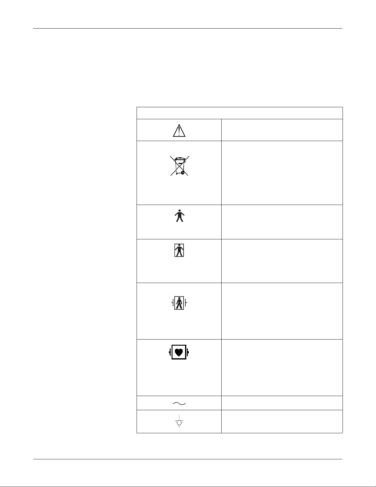
Equipment Symbols
ATTENTION: Consult accompanying documents.
WASTE OF ELECTRICAL AND ELECTRONIC
EQUIPMENT (WEEE): This symbol indicates that
the waste of electrical and electronic equipment
must not be disposed as unsorted municipal waste
and must be collected separately. Please contact
an authorized representative of the manufacturer
for information concerning the decommissioning of
your equipment.
TYPE B EQUIPMENT: Type B equipment is
suitable for intentional external and internal
application to the patient, excluding direct cardiac
application.
TYPE BF EQUIPMENT:
suitable for intentional external and internal
application to the patient, excluding direct cardiac
application. Type BF equipment has an F-type
applied part.
DEFIBRILLATOR-PROOF TYPE BF EQUIPMENT:
Type BF equipment is suitable for intentional
external and internal application to the patient,
excluding direct cardiac application. Type BF
equipment is type B equipment with an F-type
isolated (floating) part. The paddles indicate the
equipment is defibrillator proof.
TYPE CF EQUIPMENT: Type CF equipment is
suitable for intentional external and internal
application to the patient including direct cardiac
application. Type CF equipment is F-type applied
part that provides a higher degree of protection
against electric shock than that provided by Type
BF applied parts.
Type BF equipment is
ALTERNATING CURRENT (AC).
EQUIPOTENTIALITY.
1-10 250cx Series Maternal/Fetal Monitor Revision C
2036946-001

Safety: Equipment Symbols
O POWER OFF: disconnection from the mains.
I POWER ON: connection to the mains.
Equipment Symbols
VGA connection.
Revision C 250cx Series Maternal/Fetal Monitor 1-11
2036946-001

Safety: Equipment Symbols
1-12 250cx Series Maternal/Fetal Monitor Revision C
2036946-001

2 Introduction
Revision C 250cx Series Maternal/Fetal Monitor 2-1
2036946-001

For your notes
Introduction:
2-2 250cx Series Maternal/Fetal Monitor Revision C
2036946-001

About the Manual
Purpose
Intended Audience
Illustrations
Introduction: About the Manual
This manual documents all possible parameters so that when your equipment is
upgraded, new documentation will not be required. Also, the manual provides an
opportunity to read about features you may not have, to assist you with your upgrade
decisions. Some sections will not apply to your unit’s monitoring capabilities.
This manual is intended for physicians, nurses and midwives. Clinical professionals
are expected to know the medical procedures, practices, and terminology required to
monitor obstetrical patients.
All illustrations are provided as examples only. Your monitor may not be equipped
with the specific feature shown. In addition, unless explicitly stated, the display
examples do not represent your equipment setup or displayed data.
Fetal Monitoring Indications for Use
A Corometrics 250cx Series Fetal Monitor is used for fetal surveillance.
Surveillance
A Corometrics 250cx Series monitor can be used for routine non-invasive and
invasive fetal monitoring throughout labor and delivery.
Maternal Monitoring Indications for Use
A Corometrics 250cx Series Maternal/Fetal Monitor is intended for monitoring
maternal vital signs to help assess maternal well-being. The vital signs which can be
measured are summarized below.
NOTE: Maternal vital signs provided by the monitor should only be used
as an adjunct to patient assessment and must be used in
conjunction with clinical signs and symptoms.
Blood Pressure
The monitor is intended for use only in the non-invasive monitoring of maternal
blood pressure (NIBP). This monitor is not intended for use in neonatal or pediatric
blood pressure monitoring.
Revision C 250cx Series Maternal/Fetal Monitor 2-3
2036946-001

Pulse Oximetry
Heart/Pulse Rate
Series Overview
Introduction: Series Overview
The monitor is intended for use in the non-invasive monitoring of the functional
oxygen saturation of maternal arterial blood (MSpO
The monitor is intended for use in the non-invasive monitoring of the maternal
heart/pulse rate (MHR/P).
NOTE: The Corometrics 250cx Series provides both maternal heart rate
and maternal pulse rate data; the heart rate data is derived from
the MECG section of the monitor while the pulse rate data is
derived from the NIBP or MSpO
The Corometrics 250cx Series monitor provides one solution for high-risk and lowrisk labors and deliveries. The monitor lets you start with a fetal or maternal/fetal
monitor and add the extended features later, as your clinical needs increase and your
budget allows. The model of the monitor determines which parameters are in your
monitor.
).
2
sections of the monitor.
2
MODEL Fetal Heart
256cx
259cx
The 250cx Series Monitor Features
The 250cx Series monitor offers the following features:
System Parameters (256cx and 259cx)
The QVGA LCD display, with circularly polarized filter, removes glare; its
wide viewing angle provides sharp viewing at a distance.
The large display area provides simultaneous display of fetal par a met e rs,
maternal parameters, and maternal waveform s.
The Brightness softkey permits clear viewing in all lighting conditions.
Frequently used functions are controlled by your choice of front panel monitor
buttons—Volume, UA Reference, Alarm Silence, Mark [Offset], Record, and Paper
Advance.
System setup options are easily accessed via a front panel Trim Knob control.
Automatic mode selection is provided simply by inserting the appropriate
transducer plug into the front panel receptacle.
Transducer connectors are easy-to-use, color-coded, and durable.
Rate
(Twins) US
FECG TOCO
/IUP
NIBP MSpO2MECG
999
999999
2-4 250cx Series Maternal/Fetal Monitor Revision C
2036946-001

Introduction: Series Overview
Annotations from an optional Model 2116B Keyboard are printed on the strip
chart recorder paper.
The strip chart recorder is a quiet, easy-to-load, high-resolution thermal array
printer. The recorder prints continuous trends and alphanumeric data on one
strip chart.
The Chart Light allows the room lights to be dimmed without sacrificing
visibility of the strip chart recorder.
The system is compatible with Centricity
®
Perinatal Clinical Information
Systems, as well as with other information systems, to streamline capture and
archiving of patient data.
Following is a summary of the features.
Fetal Only Monitor (256cx) Maternal/Fetal Monitor (259cx)
US US
US2 US2
FECG FECG
Fetal Parameters
TOCO TOCO
IUP IUP
NIBP
MSpO
MECG
Dual ultrasonic heart rate monitoring allows for non-invasive monitoring of twins.
Independent volume controls facilitate easy transducer placement when
2
monitoring twins.
A +20 bpm heart rate offset option is provided for the secondary heart rate
(HR2) trend, when using dual ultrasound, or ultrasound and direct FECG, to
separate overlapping FHR trends for easy interpretation.
A heartbeat coincidence detection feature can be enabled to inform you when
there is the possibility that you may be monitoring a duplicate signal.
The FECG waveform can be optionally displayed and can be “frozen” on the
screen for review. In addition, a 6-second “snapshot” can be printed on the strip
chart paper.
Fetal parameters are continuously displayed even during configuration of
system setup options.
The ultrasound mode provides clean, accurate traces with few “dropouts”
because of Corometrics’ patented autocorrelation processing.
Fetal heart rate alarm limits are user-defined, with pre-set defaults. Signal
quality has no user-defined parameters.
Alarm limits are easily configured via setup screens.
Alarm silencing is controlled by a brig h tly colored, easily recognizable front
panel monitor button.
Revision C 250cx Series Maternal/Fetal Monitor 2-5
2036946-001

Introduction: Series Overview
Alarm conditions have both audible and visual indications. Only fetal audible alarms
can be disabled. Fetal heart rate threshold and signal quality alarms can be cancelled.
Optional Spectra Alerts™ simultaneously analyzes FHR and UA information
and notifies clinicians of deviations from the norm.
Maternal Parameters (259cx only)
Built-in maternal vital signs monitoring eliminates the need for separate blood
pressure and maternal pulse oximetry monitors.
Maternal vital signs storage provides an 8-hour history of the maternal vital
signs in a spreadsheet format. The data can be displayed or printed on-demand.
A maternal-only recording mode is specifically designed for postpartum
monitoring of the mother.
The monitor can be interfaced to the most widely used non-invasive blood
pressure monitors and pulse oximeters.
Maternal non-invasive blood pressure readings can be taken on-demand or at
pre-programmed intervals. The use of unique, patented DINAMAP
SuperSTAT blood pressure technology provides blood pressure accuracy and
faster, automated readings.
Smart BP option prevents blood pressure readings from occurring during
contractions.
Continuous non-invasive MSpO
be reliably monitored using well-known user-preferred pulse oximetry brands.
Masimo SET, Nellcor OxiMax, or Ohmeda TruSignal MSpO
at the time of purchase or changed later as determined by hospital needs.
The MSpO
“frozen” on the screen for review. In addition, a 6-second “snapshot” can be
printed on the strip chart paper.
Continuous display/printing of the maternal pulse rate trend can be enabled.
The MECG waveform can be optionally displayed and can be “frozen” on the
screen for review. In addition, a 6-second snapshot can be printed on the strip
chart paper.
Built-in independent MECG monitoring is provided with selection of lead I, II, or III.
Selectable 3-lead maternal ECG with pacemaker detection and rejection
generates maternal heart rate, QRS waveform display and a 6-second snapshot
printout when requested.
Twins and maternal monitoring can be accomplished simultaneously using dual
ultrasound and MECG, or by using ultrasound, FECG, and MECG.
Maternal alarm limits are user-defined, with preset defaults; they are easily
configured via setup screens.
Maternal alarm conditions have audible and visual indications, and can be
silenced for a user-specified time.
Alarm silencing is controlled by a brig h tly colored, easily recognizable front
panel monitor button.
®
oxygen saturation and maternal pulse rate can
2
may be selected
2
pulsatile waveform can be optionally displayed and can be
2
Adding Fetal Movement Detection and/or Spectra Alerts
The monitor can be upgraded to include Fetal Movement Detection and/or Spectra
Alerts. Contact your local sales representative for upgrade information.
2-6 250cx Series Maternal/Fetal Monitor Revision C
2036946-001

3 Controls, Indicators, and
Connectors
Revision C 250cx Series Maternal/Fetal Monitor 3-1
2036946-001

For your notes
Controls, Indicators, and Connectors:
3-2 250cx Series Maternal/Fetal Monitor Revision C
2036946-001

Controls, Indicators, and Connectors: Front Panel Description
Front Panel Description
W
V
A
B
C
E
D
F
Y
FMD
FECG
X
U
165
NIBP
130/ 85
MAP (107)
FECG
Print Freeze Alarms Setup VSHX
172
15:00
03:15
US2
MECG
87
HBC
TOCO
30
MSpO2
98%
25 mm/s
II 2x
03:22:45
H
G
I
J
K
L
M
S
T
R
P
Q
O
N
Monitor Front Panel
Front Panel
# Name Description
A Display The monitor’s display is divided into several sections. The content and layout of the
display can change, depending on which functions are installed in the monitor and the
modes of operation in use.
B Trim Knob Control Operation of the monitor is controlled by using the front panel buttons in conjunction
with the Trim Knob control. This control selects softkeys on the display and positions a
cursor within a setup screen. Rotate the Trim Knob control left or right to highlight
items on the screen with a bar cursor. After highlighting the desired item, press the
Trim Knob control to make the selection. In summary: rotate to move cursor; press to
select an item.
C NIBP Start/Stop Button This button starts and stops both manual and automatic blood pressure
determinations. It also provides a “shortcut” for changing the auto interval time
(see 8-12).
D Test Button Pressing and holding this button for 1 second starts or stops a monitor self-test routine.
Revision C 250cx Series Maternal/Fetal Monitor 3-3
2036946-001

Controls, Indicators, and Connectors: Front Panel Description
Front Panel
# Name Description
E Mark [Offset] Button The Mark [Offset] button is a multi-function button.
Mark: Pressing this button prints an event mark on strip chart paper (on the
bottom two lines of the top grid).
Offset: When the Heart Rate Offset mode is enabled, pressing and holding this
button shifts the secondary FHR trend +20 bpm for visibility purposes. Refer to
“Fetal Heart Rate Offset” on page 5-11.
F UA Reference Button The UA Reference button sets a baseline for uterine activity pressure monitoring.
Refer to Chapter 6, “Uterine Activity Monitoring”.
G Paper Advance Button Pressing this button advances chart paper at a rate of 40 cm/min for as long as the
button is held down.
H Record Button The Record button selects one of three recorder states: on, maternal-only mode, or
off. Refer to Chapter 11, “Recorder Modes”. Factory default is OFF.
I Power Indicator The indicator lights green when the monitor is turned on.
J Record Indicator Indicator Status Recorder Status
on on
off off
three short flashes maternal-only mode
every 5 sec
flashes on and off error condition
K Light Button Illuminates the strip chart paper for night time visibility. Factory default is ON.
L Recorder Door Latch Opens the strip chart recorder door to add, remove, or adjust the paper.
M Power Switch Moving the switch to the on position (I) turns the monitor on; moving the switch to the
off position (O) turns the monitor off.
N Strip Chart Recorder Annotations and trends are printed on the strip chart paper. Two paper styles are
available. Refer to Chapter 4, “Setup Procedures”, for instructions on loading strip
chart paper into the recorder. Refer to Chapter 11, “Recorder Modes” for additional
information about trends and annotations.
O MATERNAL NIBP Connector Connect a pneumatic hose and blood pressure cuff assembly to this black twin lumen
receptacle.
P MATERNAL SpO
Connector Connect a 250cx Series MSpO2 intermediate cable to this royal blue receptacle. Use
2
only Nellcor Maternal Oxygen Saturation Sensors if Nellcor technology is installed in
your monitor, Masimo Sensors if Masimo technology is installed in your monitor, or
Ohmeda Sensors if Ohmeda technology is installed in the monitor.
Q FECG/MECG Connector Connect an FECG cable/legplate or MECG cable plug to the FECG/MECG receptacle.
Cables with rectangular plugs connect directly to the FECG/MECG receptacle. Cables
with round plugs require an FECG/MECG adapter. Refer to “MECG Ordering
Information” on page 18-5 for the adapter part number. This adapter is used for dual
ECG monitoring as well. The adapter branches into two cables, each with a round
receptacle at the end: one branch is labeled MECG; the other branch is labeled FECG.
3-4 250cx Series Maternal/Fetal Monitor Revision C
2036946-001

Controls, Indicators, and Connectors: Front Panel Description
Front Panel
# Name Description
R UA Connector Connect a tocotransducer, IUPC, or strain gauge transducer plug to this white
receptacle. Contact your Sales Representative for information about compatibility.
S US2 Connector Connect the secondary ultrasound transducer plug to this light gray receptacle.
T US Connector Connect the primary ultrasound transducer plug to this light gray receptacle.
U FHR2 Volume Decrease Button
V FHR2 Volume Increase Button
W FHR1 Volume Decrease Button
The four Volume buttons raise ( ) and lower ( ) the volume of sound emitted by
the rear panel speaker. The upper pair controls the volume for FHR1. The lower pair
controls the volume for FHR2. Volume settings have no effect on the processing used
to determine heart rate. The Volume buttons work in conjunction with the volume
control settings on the US/US2 Setup screen (page 5-3) and on the FECG Setup
X FHR1 Volume Increase Button
screen (page 5-5).
Y Alarm Silence Button Pressing this button removes the audible indication of an individual alarm. (Refer to
Re-Alarm in the “Alarms” Section for more information.)
Revision C 250cx Series Maternal/Fetal Monitor 3-5
2036946-001

Controls, Indicators, and Connectors: Front Panel Displays
Front Panel Displays
The monitor is divided into two main sections: patient information (the left-side of
the monitor) and monitor functionality (the right-side of the monitor). Refer to
“Monitor Front Panel” on page 3-3. The keys are ordered for user efficiency.The
content and layout of the display can change, depending on which functions are
installed in the monitor and the modes of operation in use.
Primary Labor
Parameters
(Fetal)
Additional
Parameters
(Maternal)
Maternal and Fetal Parameters
Display Summary
Display Section Item Mode
Fetal Heart Rate 1 (FHR1) US, US2, FECG, or INOP
Primary Labor Parameters
(upper portion of monitor)
Fetal Heart Rate 2 (FHR2) US, US2, or INOP
Uterine Activity (UA) TOCO, IUP, or INOP
Maternal Blood Pressure NIBP
Additional Parameters
(Available in Maternal/Fetal
Monitor only)
Waveform Fetal ECG Waveform, Maternal ECG Waveform, or
Time Current Time, [Label] Frozen Message and Time of
Maternal Heart/Pulse Rate MECG, Pulse or INOP
Maternal SpO
2
MSpO
2
FECG, MECG, MSpO
Maternal SpO
Pulsatile Waveform
2
—
Activation
Softkeys System Configuration Softkey Controls —
, or Off
2
3-6 250cx Series Maternal/Fetal Monitor Revision C
2036946-001

Display Example
Controls, Indicators, and Connectors: Front Panel Displays
From the graphic below, you can determine the following:
Blood pressure is not active as indicated by the absence of numerics.
Maternal pulse oximetry is active by presence of pulse amplitude indicator.
MECG is selected as the heart rates source as indicated by the MECG mode title
softkey—rather than Pulse.
The MECG waveform is displayed at 25 mm/sec, at a size of 2x, with lead II
selected.
Heartbeat coincidence is enabled as indicated by the HBC acronym in the
primary labor parameters area.
All alarms are enabled as indicated by .
Maternal/Fetal Monitor Display Example
Revision C 250cx Series Maternal/Fetal Monitor 3-7
2036946-001

Controls, Indicators, and Connectors: Primary Labor Parameters
Primary Labor Parameters
The primary labor parameters section displays FHR1, FHR2, and UA data.
FHR Display
The FHR1 and FHR 2 areas are summarized in the following figure and table.
C
B
A
FHR Display
Name Description
FHR Value Up to three digits indicate the fetal heart rate in
A
FHR Alarm Setting
Indicator
B
beats per minute.
This symbol provides information about the FHR
audio alarm and the FHR high/low alarm limit
settings. See Chapter 10, “Alarms” for more
information.
: All alarm settings are enabled.
D
FHR Display
At least one fetal alarm is disabled.
FHR Mode Title An abbreviation indicates the monitoring mode in
use: FECG, US, US2, or INOP. (FECG only
C
D FHR Heartbeat Indicator Flashes with each detected valid heartbeat.
3-8 250cx Series Maternal/Fetal Monitor Revision C
2036946-001
displays in the FHR1 area.) Select the mode
softkey to access the respective setup screen. See
“Connectors vs. Display Modes” Table below for
FHR connection options.

Controls, Indicators, and Connectors: UA Display
B
Connectors vs. Display Modes
UA Display
Active Connectors
FECG
FECG/US
FECG/US2
US
US/US2
US2
—
1
FECG/US/US2
1
If three FHR transducers are plugged in, the FECG signal overrides the US signal.
FHR1 Area FHR2 Area
FECG INOP
FECG US
FECG US2
US INOP
US US2
US2 INOP
INOP INOP
FECG US2
The UA area is summarized by the following figure and table.
A
UA Display
UA Display
Name Description
UA Value Up to three digits indicate the uterine activity
value—mmHg or kPa. Internal UA monitoring is
A
absolute and external monitoring (Toco) is relative.
The units are consistent in both cases and are
user-selectable: mmHg or kPa.
UA Mode Title An abbreviation indicates the monitoring mode in
B
use: TOCO, IUP, or INOP.
Revision C 250cx Series Maternal/Fetal Monitor 3-9
2036946-001

Controls, Indicators, and Connectors: Additional Parameters
Additional Parameters
The additional parameters area displays NIBP, MHR/P, and MSpO2 data.
Maternal NIBP
The maternal NIBP section is summarized in the following figure and table.
D
C
B
NIBP
E
11:41
130/ 85
MAP (107)
A
Name Description
NIBP Time Stamp The time (in 24-hour format) of the last blood
A
NIBP Values The systolic/diastolic and mean arterial pressures
B
03:15
NIBP Display
pressure measurement.
(MAP) are each indicated by up to three digits—
displayed as XXX mmHg or XX.X kPa. All kPa
readings are displayed to 1/10 kPa.
During a determination, the instantaneous cuff
pressure displays in place of the mean arterial
pressure and is denoted by the title Cuff.
NIBP Display
NIBP Alarm Setting
Indicator
C
NIBP Mode Title Select the mode title to access the NIBP Setup
D
NIBP Countdown Timer The clock symbol represents activation of the auto
E
3-10 250cx Series Maternal/Fetal Monitor Revision C
2036946-001
This symbol provides information about the NIBP
audio alarm and the NIBP high/low alarm limit
settings. See Chapter 10, “Alarms” for more
information. Maternal alarms cannot be disabled.
screen.
mode. The countdown timer indicates the minutes
and seconds until the next automatic reading.

MHR/P Area
Controls, Indicators, and Connectors: MHR/P Area
The MHR/P area is summarized by the following figure and table.
C
D
B
A
MHR/P Display
MHR/P Display
Name Description
MHR/P Value Up to three-digits indicate the MHR/P in beats per
A
MHR/P Alarm Setting
Indicator
B
minute.
This symbol provides information about the MHR/P
audio alarm and the MHR/P high/low alarm limit
settings. See Chapter 10, “Alarms” for more
information. Maternal alarms cannot be disabled.
MHR/P Mode Title The mode title MECG indicates MECG is the
MHR/P source; the mode title Pulse indicates
MSpO
C
or NIBP is used as the source. Select the
2
mode title softkey to access the MHR/P Setup
screen.
Maternal Heartbeat
D
Indicator
Flashes with each detected valid heartbeat—for
MECG only.
Revision C 250cx Series Maternal/Fetal Monitor 3-11
2036946-001

MSpO2 Area
Controls, Indicators, and Connectors: MSpO2 Area
The MSpO2 area is summarized in the following figure and table.
C
B
D
MSpO2
A
Name Description
Value Up to three digits indicate the percentage of
MSpO
A
B
2
MSpO
2
Indicator
Alarm Setting
97%
MSpO
Display
2
MSpO
Display
2
oxygen in the mother’s blood.
This symbol provides information about the MSpO2
audio alarm and the MSpO
settings. See Chapter 10, “Alarms” for more
information. Maternal alarms cannot be disabled.
high/low alarm limit
2
MSpO
Mode Title Select the mode title to access the MSpO2 Setup
C
D
2
MSpO
Pulse Amplitude
2
Indicator
Waveform Area
The waveform area displays approximately 4 seconds of waveform data for: FECG,
MECG, or MSpO
. Refer to Chapter 14, “Waveforms” for more information.
2
Time and Waveform Message Area
The current time (in 24-hour format) always displays on the far right. When a
waveform is frozen, the message Frozen displays on the far left, bottom corner, along
with the time of activation.
screen.
This vertical bar qualitatively indicates pulse
amplitude.
3-12 250cx Series Maternal/Fetal Monitor Revision C
2036946-001

Controls, Indicators, and Connectors: Softkeys
Battery-Backed RAM Status
Whenever you turn off a 250cx Series Monitor, a battery provides power to the
RAM (random access memory) that stores information such as time, date, default
settings, etc.
The icon shown above will appear in the upper right-hand section of the monitor
under the following circumstances.
Battery-Backed RAM Status
Icon Appearance Reason Solution
Low Battery Icon
Icon appears and then disappears after
power cycle.
Icon appears after multiple power
cycles.
SET TIME/DA TE message prints on the
strip chart paper.
Softkeys
Mode Title Softkeys
Waveform Softkeys
Data corruption. Your monitor has reverted
to factory settings.
Battery requires service. Call GE Service to report.
Failure of the battery-backed RAM to retain
time and date.
A softkey is an area on the screen that can be selected with the Trim Knob control.
When the softkey is activated by pressing the Trim Knob control, it may cycle
through available settings or it may display a setup screen.
Most of the mode titles in the display are also softkeys which give access to
corresponding setup screens:
US, US2, FECG, NIBP, MECG, Pulse
Access setup screens and configure lastused settings.
Reset the time and date then power cycle
the monitor. If message still prints, call GE
Service to report.
, and
MSpO2.
The waveform title is a softkey used to select the waveform for display or to disable
the area. The ECG Scaling and MECG lead labels are softkeys used to configure the
waveform currently displayed.
Revision C 250cx Series Maternal/Fetal Monitor 3-13
2036946-001

Controls, Indicators, and Connectors: Softkeys
Dedicated Softkey Area
Softkeys are located at the bottom of each screen, as shown in “Maternal/Fetal
Monitor Display Summary” on page 3-14. Although there are many possible
softkeys which may appear in this area, a maximum of five are shown at a time.
US
165
NIBP
130/ 85
MAP (107)
03:15
I
MECG 09:21:41 Frozen
Print Freeze Alarms Setup VSHX
H
02:15
G
US2
172
MECG
89
F
HBC
E
TOCO
30
MSpO2
97%
25 mm/s
II Auto
09:22:06
D
A
B
C
Maternal/Fetal Monitor Display Summary
Display Summary
Name Description
Mode Title Softkeys Selects US, US2, FECG, NIBP, MHR/P, or SpO
A
B ECG Scale Softkey Selects 0.25x, 0.5x, 1x, 2x, 4x, or Auto.
MECG Lead Select
C
Softkey
VSHX Softkey Displays maternal Vital Signs History screen. (See
D
E Setup Softkey Displays General Setup screen
F Alarms Softkey Displays Master Alarm Setup screen.
3-14 250cx Series Maternal/Fetal Monitor Revision C
2036946-001
Setup screens.
Selects Lead I, II, or III.
illustration below.)
2

Controls, Indicators, and Connectors: Softkeys
Display Summary
Name Description
Freeze Softkey Freezes waveform for analysis; unfreezes
G
Print Softkey Prints 6-second snapshot of frozen waveform, real-
H
waveform to return to real-time display.
time waveform, or maternal vital signs history.
Waveform Softkey Selects FECG, MECG, MSpO
I
US
154
Date: 24-Mar 24-Mar 24-Mar 24-Mar 24-Mar
Time: 12:00 12:10 12:20 12:30 12:40
NIBP
SYS 120 122 122 125 124
DIA 85 87 90 95 90
MAP 94 95 94 105 98
P7476758177
MSpO2
%02 98 99 99 100 98
P7677758178
MECG 75 74 75 81 78
Print PrintAll ExitView
A
US2
135
Vital Signs History
HX Interval: 10 min
B
, or Off.
2
TOCO
17
C
D
l Maternal Vital Signs History Screen Softkeys
Maternal Vital Signs History Screen Softkeys
Name Description
A Print Softkey Prints one page (screen) of the table.
B PrintAll Softkey Prints all pages (screens).
View Softkey Scrolls through the data:
C
D Exit Softkey Returns to the previous screen.
Revision C 250cx Series Maternal/Fetal Monitor 3-15
2036946-001
Counterclockwise for newest data
Clockwise for oldest data

Controls, Indicators, and Connectors: Rear Panel Description
J103
J10
J109
C
J110
C
J111
C
J10
J104
00W
a
ß
y
e
c
0086
3
9
Rear Panel Description
B
D
F
A
240
120
100 -120V ~ 50-60HZ 1
M
C
1
U.S. PATS. 3,982,528 4,533,926 4,573,47
CANADIAN PATS. 1,057,360 1,214,14
GE Medical Systems In
European Representativ
Munzinger Str
K
E
2
e 3-5; D-79111 Freiburg German
RS232
I
RS232
J112
CAUTION: FEDERAL
LAW RESTRICTS THIS
DEVICE TO SALE BY
OR ON THE ORDER OF
A PHYSICIAN.
RS232
!
G
N
L
J
H
Monitor Rear Panel Connectors (Standard and Optional)
IMPORTANT: The Fetal Acoustic Stimulator and Remote Event
Marker connectors are identical in size and shape. Be sure you connect to
the proper connector to ensure accurate information.
250cx Series Rear Panel (Standard and Optional Features)
Name Description
Vent Provides ventilation for the monitor’s internal
A
B
C
D
J101 Telemetry
Connector
J103 Data Entry
Connector
J104 Nurse Call
Connector
circuitry.
Connector for Corometrics telemetry system
interface.
Connector for data entry system interface.
Connector for standard Nurse Call System
interface. The connector’s maximum output is 50
Vdc at 100 mA; the maximum on resistance is
0.5 Ω.
3-16 250cx Series Maternal/Fetal Monitor Revision C
2036946-001

Controls, Indicators, and Connectors: Rear Panel Description
250cx Series Rear Panel (Standard and Optional Features)
Name Description
J102 Central Systems
E
Connector
J112 External VGA
Connector
F
Connector for analog central station system
interface.
Connector for external VGA display. Use of
recommended GE external display will allow
monitor front panel display video to be replicated
remotely.
Speaker The rear panel speaker emits an audible tone for
G
heart rates, MSpO
pitch, and alarms. It also provides the sound for the
pulse with %O2-dependent
2
song player feature.
J109, J110, and J111
RS-232C
H
Communications
Three serial RJ-11 connectors are provided for
interfacing to peripheral equipment. Contact your
GE Service Representative for more information.
Connectors
ECG Out Connector External recorder receptacle for MECG signals.
I
Fetal Acoustic
Stimulator Connector
J
The standard output level is 1 V/mV.
Receptacle for Corometrics Model 146 Fetal
Acoustic Stimulator (FAST). A musical note symbol
prints on the strip chart paper each time the Model
146 is used:
Remote Event Marker
Connector
Receptacle for the Corometrics Remote Event
Marker. When activated, one of the following marks
prints on the strip chart paper:
The event marker is commonly used to record
K
an “event”:
The fetal movement marker (default setting) is
commonly used as an indication that the mother
has perceived fetal movement:
Refer to the “Coro 250/250cx Series Monitor
Service Manual” for more information.
Equipotential Lug A binding post terminal is directly connected to the
L
chassis for use as an equipotentiality connection.
Revision C 250cx Series Maternal/Fetal Monitor 3-17
2036946-001

Controls, Indicators, and Connectors: Rear Panel Description
250cx Series Rear Panel (Standard and Optional Features)
Name Description
AC Voltage Selection
Switch
This switch is intended for qualified service
personnel to select a voltage range for the AC
input:
M
120: Accepts an AC input in the range of 100–
120 VAC.
240: Accepts an AC input in the range of 220–
240 VAC
Power Entry Module AC line power cord receptacle. Refer to the rear
N
panel markings to verify line voltage and line
frequency requirements.
CAUTION
NON-DESTRUCTIVE VOLTAGE—The maximum nondestructive voltage that may be applied to the rear panel
connectors is 0 volts. Do not attempt to connect cables to these
connectors without contacting your Biomedical Engineering
Department or GE Medical Systems Information Technologies
Service Representative. This is to ensure the connectors comply
with leakage-current requirements of one of the following
applicable standards: Underwriters Laboratories UL-2601-1,
Canadian Standards Associations CSA 22.2 No. 125, or
International Electrotechnical Commission EN60601-1.
3-18 250cx Series Maternal/Fetal Monitor Revision C
2036946-001

4 Setup Procedures
Revision C 250cx Series Maternal/Fetal Monitor 4-1
2036946-001

For your notes
Setup Procedures:
4-2 250cx Series Maternal/Fetal Monitor Revision C
2036946-001

Setup Procedures: Loading Strip Chart Recorder Paper
Loading Strip Chart Recorder Paper
Refer to “Paper Supplies Ordering Information” on page 18-3 to order paper
required for use with the 250cx Series Monitor.
(HR scale of 30–240 bpm); or
(HR scale of 50–210 bpm).
Refer to Chapter 11, “Recorder Modes” for more information about the different
paper styles.
CAUTIONS
LOADING PAPER—The instructions for loading paper into the
250cx Series Monitor are different than the instructions for
loading paper into other Corometrics monitors. Im proper loading
can cause paper jams. Follow the instructions carefully.
PAPER TYPE—Do not use non-Corometrics paper or paper
designed for use with other Corometrics monitors. Using incorrect
paper may produce inferior print quality, could result in
permanent damage to the recorder’s print head, and may void your
warranty . Refer to “Paper Supplies Ordering Information” on
page 18-3 for the correct monitor paper part number.
STORAGE/TRANSPORT—Paper should be installed in the
monitor’s strip chart recorder at all times. This reduces particle
build-up on the printhead and facilitates opening the recorder
door.
To install Corometrics chart paper in the 250cx Series Monitor, follow these steps:
1. Press down on the latch on the right side of the strip chart recorder door to open
the recorder door.
Opening the Recorder Door
Revision C 250cx Series Maternal/Fetal Monitor 4-3
2036946-001

Setup Procedures: Loading Strip Chart Recorder Paper
2. Fan the pack of Z-fold paper on all sides to loosen any folds and to ensure
proper feed of the paper through the recorder.
NOTE: The black squares indicate the end of the recorder paper. When the black
squares appear, the strip chart recorder has approximately 20 minutes of
paper remaining, when running at a speed of 3 cm/min.
Fanning the Paper
3. Hold the package of paper so that:
the black squares are on the bottom of the pack; and
the Corometrics logo and page numbers are on the left side of the pack.
Orienting the Paper
NOTE: The paper is labeled, “This side up for the 120, 2120is, and 170 Series.”
This paper is compatible with and required for the 250cx Series.
4-4 250cx Series Maternal/Fetal Monitor Revision C
2036946-001

Setup Procedures: Loading Strip Chart Recorder Paper
5
9
1
4. Unfold two sheets from the top of the package so that they extend toward you.
5. Place the pack in the drawer so that the pack is laying flat in the recorder.
Creating Paper Leader
Inserting the Paper
6. Close the strip chart recorder door.
Closing the Recorder Door
Revision C 250cx Series Maternal/Fetal Monitor 4-5
2036946-001

Power
Setup Procedures: Power
Refer to Chapter 11, “Recorder Modes” for information about paper-loading errors.
1. Turn the monitor’s power off. The Power button is located in the lower righthand corner of the monitor.
2. Connect the detachable line cord to the rear panel power connector; plug the other
end into a hospital grade grounded wall outlet of appropriate voltage. (If you are
unsure about the voltage, contact your hospital Biomedical Engineering
Department or GE Service Representative.)
Interruption of Power
120
240
Attaching the Power Cord
3. Turn the monitor’s power on. The green indicator light, located near the up per
left-hand corner of the Light button, illuminates and a series of tones are heard,
indicating that the monitor has been turned on.
When the supply main to the monitor is interrupted for more than 30 seconds, the
following behaviors occur.
Configuration Settings: The configuration settings are restored to the current
user-selected default setting: Factory or Hospital.
Patient Data: The stored patient data—including vital signs history—are erased.
NIBP: The NIBP parameter reverts to Manual Mode.
4-6 250cx Series Maternal/Fetal Monitor Revision C
2036946-001

Self-Test Routine
Setup Procedures: Self-Test Routine
The 250cx Series Monitor contains a self-test routine which checks the calibration
and internal circuitry of the monitor. Initiate the self-test routine at the beginning of
each monitoring session to print the results on the patient’s strip chart.
NOTE: To stop a self-test routine that
is in progress, press the
open the recorder door.
Test Routine Description
Display Test All display pixels extinguish for one second and then illuminate for one second. A green horizontal line
Lamp Test The yellow Record indicator illuminates.
Recorder Test The message TEST: ARE ALL DOTS PRINTED? prints followed by two vertical lines and four
Counting Test After the recorder test, the display returns to the main screen. The software generates a 120 bpm rate
Uterine Activity The monitor sets UA value to 50 mmHg and displays in the UA display area; the mode title displays
Test button or
moves down on a red background followed by a blue vertical line moving from left to right.
horizontal lines. The two vertical lines should appear continuous and indicate a fully functional
printhead. The four horizontal lines align with the heart rate and uterine activity scales, i.e., 30 and
240 BPM or 50 and 210 BPM, and 0 and 100 mmHg (0.0 and 13.3 kPa).
in the FHR1 area, a 180 bpm rate in the FHR2 area, and both mode titles display Test.
Test.
1. Ensure that strip chart is loaded.
2. Press the
3. Refer to the table below and ensure the test results are produced as expected. At
the successful completion of the self-test routine, the monitor is ready for use.
Test button.
Monitor Self-Test Routines
Setup Screens
The 250cx Series Monitor provides a variety of options that are selected using the
setup screens shown on the display. (The illustrations in this section are
representative of all possible features. Your monitor screens may vary.) All functions
are performed easily using the front panel Trim Knob control. Setup screens for
FECG, US/US2,
Revision C 250cx Series Maternal/Fetal Monitor 4-7
Maternal
2036946-001
NIBP, MHR/P, and MSpO
are detailed in Chapter 5.
2

Setup Procedures: Setup Screens
Using the Trim Knob Control
General instructions for using the Trim Knob control follow:
NOTE: When any setup screen (except
the General Setup screen) is displayed,
the primary labor parameters remain
displayed.
1. To display a parameter setup screen, rotate the Trim Knob control until the bar
cursor highlights the title of the parameter (FECG, US, US2, NIBP , MECG, Pulse, or
MSpO
). To access the Master Alarm Setup screen or the General Setup screen,
2
rotate the Trim Knob control until the bar cursor highlights the Alarms softkey or
the Setup softkey, respectively, on the bottom of the screen.
2. Press the Trim Knob control once to display the selected setup screen.
3. While the screen is displayed, rotate the Trim Knob control until the desired
field is highlighted.
4. Press the Trim Knob control again to activate the selected field. The cursor
flashes to indicate the field is active.
5. Rotate the Trim Knob control in either direction to cycle through the available
choices for the field.
6. When the desired selection is made for the field, press the Trim Knob control
once to confirm the selection.
7. Repeat Steps 3 through 6 until all desired settings have been made.
8. Rotate the Trim Knob control until the bar cursor highlights the Exit softkey on
the bottom of the screen. This returns the monitor to normal operation.
IMPORTANT
EFFECTIVITY—All changes take effect immediately after a selection is
enacted in Step 6. Some changes take effect as the values are changed
without having to press the Trim Knob.
4-8 250cx Series Maternal/Fetal Monitor Revision C
2036946-001

Setup Procedures: General Setup Screen
OFF
5
n
n
n
30
n
60
n
0
3
5
6
8
9
Off
y
y
y
p
ps
:
5
n
:
5
n
FSpO2 Trace:
Off
g:
Off
Song
:
5
e:
007
e:
00
:
e
t
f
n
:
.
:
e
General Setup Screen
Happy Birthda
Brahms' Lullab
Rock-A-Bye Bab
Temp Done Volum
Paper Speed Selection
1, 2, or 3 cm / min
f
Following is a sample General Setup screen.You can access this screen
screen by selecting
Setup
. Using the Trim Knob to go to the field you wish to change.
and select it by pressing the knob. Choose the desired setting.
General Setu
Play Son
Volume
Temp Done Volume
rightness
Paper Speed: 3 cm / mi
t
1-Jan-2
Tim
2:01:
External Monitor Setu
MSpO2 Print Interval
FSpO2 Print Interval
ervic
mi
mi
Exi
mi
10 mi
15 mi
mi
mi
from the main
Play Song
Song Volume
Temp Done Volume
Brightness
General Setup Screen
You can activate a song to be played from the monitor’s speaker to celebrate each
birth.
This field sets the volume of the song player.
This field adjusts the temperature completion volume. This field is only available
when the Exergen protocol is configured.
This field allows you to adjust the brightness of the backlight of the display. The
settings range from
1 to 9
with 9 being the brightest setting.
Revision C 250cx Series Maternal/Fetal Monitor 4-9
2036946-001

Paper Speed
Date
Time
Setup Procedures: General Setup Screen
The monitor offers a choice of paper speeds of the strip chart recorder.
1 cm/min: paper saving.
2 cm/min: a compromise between the 1 cm/min and 3 cm/min.
3 cm/min: recommended for greater diagnostic capability.
It is very important to set the date on your monitor prior to initial use. The month
field has a range from 01–12; the range for the day field varies according to the
1
selection for month and year
battery maintains the date even when the monitor is unplugged from AC power.
It is also very important to set the monitor’s clock prior to initial operation and
during daylight-saving time changes. A long-lasting battery maintains the set time
even when the monitor is unplugged from AC power.
; the year field has a range of 00–99. A long-lasting
MSpO2 Print Interval
FSpO2 Print Interval
FSpO2 Trace
Service
The time is represented by a 24-hour clock in hours, minutes, and seconds. The hour
field has a range of 00–23; the minutes field has a range of 00–59; the seconds field
resets when minutes change.
This field sets the time interval for printing MSpO2 values received from an
external maternal pulse oximetry monitor.
This field sets the time interval for printing FSpO2 values received from an external
fetal pulse oximetry monitor.
This field enables/disables FSpO2 trend trace printing of data received from an
external fetal pulse oximetry monitor.
By choosing this option, you can view software revisions, what type of SpO
technology your 250cx Monitor contains (i.e., Ohmeda, Nellcor, and Masimo etc.),
and allows service personnel to enter the password-protected Service Mode.
1
For example, February of 1996 has a day range of 01-29; Februar y of 1997 has a range of 01 -28; August
of 1997 has a day range of 01-31.
4-10 250cx Series Maternal/Fetal Monitor Revision C
2036946-001
2

Setup Procedures: Preparing the Monitor for Patient Use
Preparing the Monitor for Patient Use
The following procedures should be performed before use on each patient:
1. Ensure an adequate supply of paper is in the recorder. The recorder will
automatically stop when paper runs out. If the recorder requires paper, refer to
“Loading Strip Chart Recorder Paper” on page 4-3.
2. Ensure the monitor
3. Connect the appropriate transducers for monitoring. Read the “Maternal/Fetal
Monitoring, Clinical Applications Manual” for instructions on app lying the
transducers.
4. Ensure the setup menus are configured appropriately for use on this patient.
Refer to “Setup Screens” on page 4-7.
5. Turn the recorder on. Refer to Chapter 11, “Recorder Modes” for more
information.
CAUTION
PAPER MOVEMENT—Always ensure that the chart paper is
moving properly from the front of the recorder drawer when the
Record indicator light is on.
6. Press the
7. Press the
Routine” on page 4-7.
8. Check the time and date printed on the strip chart paper. Refer to “General
Setup Screen” on page 4-9 if you need to change the time/date setting.
Paper Advance button to create a paper leader.
Test button to run the monitor’s self-test routines. Refer to “Self-Test
power is on.
9. Annotate the patient name and ID# using the optional Corometrics Model
2116B Data-Entry/Clinical-Notes Keyboard, if available.
Annotating Patient Information
Revision C 250cx Series Maternal/Fetal Monitor 4-11
2036946-001

Setup Procedures: Preparing the Monitor for Patient Use
4-12 250cx Series Maternal/Fetal Monitor Revision C
2036946-001

5 Fetal Heart Rate
Monitoring
Revision C 250cx Series Maternal/Fetal Monitor 5-1
2036946-001

For your notes
Fetal Heart Rate Monitoring:
5-2 250cx Series Maternal/Fetal Monitor Revision C
2036946-001

Fetal Heart Rate Monitoring: Ultrasound (External Method)
Ultrasound (External Method)
NOTE: Refer to the “Maternal/Fetal Monitoring, Clinical Applications Manual”
for patient application information.
Methodology
An ultrasound (US/US2) transducer placed on the maternal abdomen is used to
direct an ultrasonic beam toward the fetal heart; the transducer detects Doppler
shifted frequency changes in echoes created by moving cardiac structures. An
autocorrelation process is used to determine the time interval between successive
cardiac cycles.
The fetal heart rate is displayed in bpm and is continuously plotted on the strip chart
paper if the recorder is on. (Refer to the “US/US2 Setup Screen” figure below.) The
heartbeat indicator flashes for each detected heartbeat.
US/US2 Setup Screen
Applicable Spectra
alerts can appear in
this area
Select the US or US2 softkey to access the US/US2 Setup screen below. The title of
the screen (US vs. US2) is dependent on the mode selected when the screen is
activated.
US
120
FM Detect: Off
Volume:
Alert: On
Trend
5
US2
120
US Setup
Volume 5
IUP
20
Alert Suspend: Off
Exit
US/US2 Setup Screen
Volume
This field adjusts the volume for the FHR derived from the selected mode, US or
US2. This field works in conjunction with the front panel
Revision C 250cx Series Maternal/Fetal Monitor 5-3
2036946-001
Volume buttons.

Fetal Heart Rate Monitoring: FECG (Internal Method)
Alert
This field controls and shows Spectra Alerts. Refer to Appendix C for more
information.
Alarm Volume
This field controls the alarm volume for all fetal alarms.
FECG (Internal Method)
Methodology
This method uses an electrode attached directly to the fetal presenting part. The
electrode is connected to the cable/legplate secured to the mother. The fetal heart
rate is computed based upon the interval between successive R-wave peaks of the
fetal QRS complex.
Artifact Elimination
The fetal heart rate is displayed in bpm and is continuously plotted on the strip chart
recorder paper if the recorder is on. (Refer to “US/US2 Setup Screen” on page 5-3.)
The heartbeat indicator flashes for each detected heartbeat.
An FECG artifact elimination option is available behind the password-protected
Service Lock screen on all 250cx Series Monitors.
5-4 250cx Series Maternal/Fetal Monitor Revision C
2036946-001

Fetal Heart Rate Monitoring: FECG Setup Screen
FECG Setup Screen
Select the FECG softkey to access the FECG Setup screen.
Volume
FECG
165
Volume: 5
0
1
2
3
4
5
6
On
7
Off
8
9
Alarms
FHR:
Audio Alarms:
On 5
This field controls the volume for the FHR beeps derived from FECG. Thi s field
works in conjunction with the front panel
US
172
FECG Setup
High
160 85 bpm
Volume:
TOCO
30
Low
Exit
High Low
140-200, Off Off, 60-140
0
1
2
3
4
5
6
7
8
9
FECG Setup Screen With Fetal Alarms Enabled
Volume buttons.
Alarms
These fields adjust the high and low alarm limits. The available ranges are shown in
the above figure; the factory default settings are listed in Appendix A, “Factory
Defaults”.
NOTE: The FHR1 and FHR2 alarm limits are set independently of each other.
Audio Alarms
This field enables/disables the audio alarm function for FHR when derived from
FECG.
On: Visual and audible indications are provided during an FHR alarm condition.
Off: Only a visual indication is provided during an FHR alarm condition.
Alarm Volume
This field controls the alarm volume for all alarms.
Revision C 250cx Series Maternal/Fetal Monitor 5-5
2036946-001

Fetal Heart Rate Monitoring: Fetal Heart Rate Alarms
Fetal Heart Rate Alarms
FHR Threshold Alarms
A fetal heart rate threshold alarm occurs when any fetal heart rate falls outside of the
pre-defined alarm limits—greater than the high limit setting or less than the low
limit setting. These alarm limits are configured via the user setup mode; the alarm
can be completely disabled as well.
NOTE: The alarm enable/disable setting controls all FHR alarms: high, low, and
signal quality.
A threshold alarm is indicated both visually and audibly. Visual indications are
provided by the Alarm indicator and the respective heart rate numerics. The
audio alarm is described as alternating high-low tones.
CAUTION
Prior to monitoring each patient, it is recommended that you
check the alarm status and alarm limits to ensure they are
appropriate for the patient. The alarms are disabled if the Alarm
Disable indicator is lit; they are enabled if the indicator is
unlit.
Latching Alarms
Fetal heart rate threshold alarms are “latching.” This means that a clinician must
acknowledge the alarm using the monitor’s
alarm.
Active Threshold Alarm: Press the Alarm Silence button to cancel the audio
component of an active threshold alarm. The visual indications remains present
until the FHR value returns to within the defined acceptable range.
Unsilenced, Resolved Threshold Alarm: If a threshold alarm condition
resolves, prior to being silenced (clinical acknowledgment), the visual and
audible indications both remain present. Press the
cancel both the audible and visual indications.
Alarm Silence button in order to clear the
Alarm Silence button to
5-6 250cx Series Maternal/Fetal Monitor Revision C
2036946-001

FHR High Alarm
Fetal Heart Rate Monitoring: Fetal Heart Rate Alarms
The simplest example of a high FHR alarm occurs when the FHR value is
continuously greater than the threshold (high limit) for 5 minutes. When data
consistently violates the limit, the time-to-alarm is 5 minutes.
FHR (bpm)
alarm activates
high alarm limit
(threshold)
Time (minutes)
High FHR Alarm Example
FHR Low Alarm
The simplest example of a low FHR alarm occurs when the FHR value is
continuously less than the threshold (low limit) for 30 seconds. When data
consistently violates the limit, the time-to-alarm is 30 seconds.
FHR (bpm)
low alarm limit
(threshold)
alarm activates
Time (minutes)
Low FHR Alarm Example
Revision C 250cx Series Maternal/Fetal Monitor 5-7
2036946-001

Fetal Heart Rate Monitoring: Fetal Heart Rate Alarms
Sample Clinical Exceptions
The figure below provides an example of FHR fluctuations above and below the
high alarm limit setting.
FHR (bpm)
high alarm limit
(threshold)
Time (minutes)
Fluctuations Near High Alarm Limit Example
Whether the pattern shown in the above figure generates an alarm depends on what
percentage of the data violates the limit. The monitor evaluates the data on an ongoing basis; the methodology can be simplified as follows:
An FHR threshold alarm occurs if the FHR violates the alarm limit setting for
more time than it stays within the specified acceptable range.
The time-to-alarm increases as a greater percentage of data stays within the
specified acceptable range.
Signal Quality Alarms
A fetal heart rate signal quality alarm occurs if the monitor is unable to detect an
acceptable FHR signal.
Active Signal Quality Alarm
Signal quality alarms are indicated both visually and audibly. Dashes “– – –” display
in the affected fetal heart rate display. The audio alarm is described as alternating
high-low tones.
Resolved Signal Quality Alarm
As soon as an alarm condition is resolved, both the visual and audible indications
automatically disappear (unlatch).
5-8 250cx Series Maternal/Fetal Monitor Revision C
2036946-001

100% Signal Loss
Fetal Heart Rate Monitoring: Fetal Heart Rate Alarms
In cases where there is a complete absence of signal, the signal quality time-to-alarm
is 1.25 minutes.
FHR (bpm)
100% signal loss
1.25 min
alarm activated
Time (minutes)
100% Signal Loss Example
Intermittent Signal Loss
In the clinical environment, a partial loss of signal is seen more frequently than a
complete loss of signal. The time-to-alarm will vary related to the percentage of
signal loss. Figure below shows an example where there is 70% signal loss resulting
in a signal quality alarm after 5 minutes.
FHR (bpm)
Silencing an Audio Alarm
70% signal loss
5 min
end of “good”
quality signal
70% Signal Loss Example
alarm activates
Time (minutes)
Press the Alarm Silence button to cancel the audio component of an alarm; the
visual indications remain until the alarm condition is resolved.
The silence function works on an alarm-by-alarm basis. An audio alarm will sound
if a new alarm condition occurs after the previous condition has been resolved.
Revision C 250cx Series Maternal/Fetal Monitor 5-9
2036946-001

Fetal Heart Rate Monitoring: Single Fetal Heart Rate Monitoring
Summary
The alarm algorithms are intended to assist the perinatal staff in assessing the status
of a patient at bedside by recognizing vital signs data that falls outside the userdefined normal range. The monitor does not replace observation and evaluation of
the mother and fetus at regular intervals by a qualified care provider, who will make
diagnoses and decide on treatments or interventions. A provider shoul d determine
the status of the patient by visual assessment of the fetal monitor tracing at the
bedside and evaluation of fetal and maternal vital signs and progress in labor. The
absence of an alarm does not indicate fetal or maternal well-being.
Frequent assessment of the fetal monitor tracing is necessary to ensure recognition
of unusual, undefined, or suspicious patterns that may or may not generate a
threshold alarm.
Single Fetal Heart Rate Monitoring
The Corometrics 250cx Series monitor offers three options to monitor a single fetal
heart rate (FHR):
US (external)
US2 (external)
FECG (internal)
Please refer to the “FHR Display and Trend Summary” Table for FHR display and
trend summary.
Dual Fetal Heart Rate Monitoring
The Corometrics 250cx Series monitor is capable of monitoring two fetal heart rates.
The discussion in this section is limited to methods of monitoring dual fetal heart
rates; however, it is important to note that MECG
the monitoring of twins—even when one twin is monitored using FECG. Please
refer to the “FHR Display and Trend Summary” Table for FHR display and trend
summary.
There are three available options to monitor dual fetal heart rate (FHR).
US/US2 (dual external)
FECG/US (internal/external)
FECG/US2 (internal/external)
The 250cx Series monitor offers two advanced features to aid in monitoring twins:
heartbeat coincidence
fetal heart rate offset
monitoring can continue during
5-10 250cx Series Maternal/Fetal Monitor Revision C
2036946-001

Fetal Heart Rate Monitoring: Dual Fetal Heart Rate Monitoring
FHR Display and Trend Summary
Heartbeat Coincidence
ACTIVE
CONNECTORS
US US
US2 US2
FECG FECG FECG
US, US2 US US2 US
FECG, US FECG US FECG
FECG, US2 FECG US2 FECG
FECG, US, US2 FECG US2 FECG
NOTE: In the event that three transducers are plugged into the monitor, FECG
overrides the primary ultrasound connector (US).
When the heartbeat coincidence feature is enabled, the monitor alerts you when
there is the possibility that you may be monitoring a duplicate signal. Refer to
Chapter 13, “Heartbeat Coincidence” for more information.
DISPLAY MODE TREND ANNOTATION
FHR1 FHR2 FHR1 FHR2
US
US2
US2
US
US2
US2
Fetal Heart Rate Offset
When monitoring dual fetal heart rates, overlapping traces on the strip chart may be
difficult to interpret. The 250cx Series monitor provides a +20 bpm shift for the
secondary FHR trend to alleviate this problem—whether using dual ultrasound or
ultrasound and FECG. This field provides an alternative to using the front panel
Mark [Offset] button. Refer to the service manual for information on enabling/
disabling fetal HR offset.
Activating the Fetal Heart Rate Offset Feature
To shift the secondary FHR trend +20BPM:
1. Ensure the recorder is on and two HR channels are activated.
2. Press and hold the
screen.)
When you use dual ultrasound or US2 and FECG, the US2 trace is shifted +20
bpm and the symbol prints on the upper portion of the top grid every
4.5 cm.
When you use US and FECG, the US trace is shifted +20 bpm and the
symbol prints on the upper portion of the top grid every 4.5 cm.
Mark [Offset] button for 3 seconds. (Or use the US/US2 Setup
Revision C 250cx Series Maternal/Fetal Monitor 5-11
2036946-001

Fetal Heart Rate Monitoring: Dual Fetal Heart Rate Monitoring
A right arrow (→) and a vertical dashed line print to draw attention to the start
of the shifted trend.
Refer to “Fetal Heart Rate Offset Example,” on page 5-12 for an example of a
shifted trend.
De-Activating the Fetal Heart Rate Offset Feature
After the FHR patterns have been assessed, set the secondary FHR trend back to the
1
normal (unshifted) position.
1. Ensure the recorder is on.
NOTE: If the auto-revert (10-min)
setting is selected on the passwordprotected Install Options screen, the
shifted heart rate trace automatically
reverts to normal after 10 minutes.
2. Press and hold the
Mark [Offset] button for 3 seconds. (Or use the US/US2 Setup
screen.)
The trend returns to the unshifted position.
A left arrow (←) and a vertical dashed line print to draw attention to the
change.
1
Setting the FHR trend to the normal (unshifted) mode does not disable the HR
Offset function; it deactivates it. To disable the mode, refer to the 250cx Series
Service Manual.
FHR
US2+20 US2+20
FHR
240
210
180
150
120
bpmbpm
90
5810458103
60
30
US HBC TOCO 3CM/MIN US2 FMD US HBC TOCO 3CM/MIN US2 FMD
12
10
8
6
4
2
100
75
50
25
12
10
8
6
4
2
100
75
50
25
Fetal Heart Rate Offset Example
5-12 250cx Series Maternal/Fetal Monitor Revision C
2036946-001

6 Uterine Activity
Monitoring
Revision C 250cx Series Maternal/Fetal Monitor 6-1
2036946-001

For your notes
Uterine Activity Monitoring:
6-2 250cx Series Maternal/Fetal Monitor Revision C
2036946-001

Uterine Activity Monitoring: Tocotransducer (External Method)
Tocotransducer (External Method)
NOTE: Refer to the “Maternal/Fetal Monitoring, Clinical Applications Manual”
for patient application information.
Methodology
A tocotransducer applied to the maternal abdomen records relative changes in
abdominal tension caused by uterine contractions. The mode (TOCO) and value are
shown in the UA area of the display. During normal operation, the UA value displays
from 0–100 in mmHg mode and 0.0 - 13.3 in kPa mode. Uterine activity is
continuously plotted on the bottom (or right) grid of the strip chart paper as a plain
black line.
IMPORTANT:
FOR TRIMLINE TOCOTRANSDUCERS ONLY—You must wait
at least 10 seconds from the time you power the monitor on or
connect a tocotransducer before pressing the
UA Reference
button.
Establishing a Baseline
Monitoring uterine activity using a tocotransducer provides relative pressure
measurements—compared to a baseline or UA reference. The quality of
measurements depends on the following:
position of the tocotransducer;
belt tension;
size of the patient; and
established baseline.
All 250cx Series Monitors provide a
a baseline is established, all pressure measurements are relative to that baseline. The
baseline can be set manually by two different methods or automatically, when
necessary. Whenever the baseline is set, the bottom line of the bottom strip chart
grid is annotated with UA REF.
Initial Referencing
The initial reference occurs automatically. After you plug in a transducer, verify that
the display reads less than 30 mmHg (4 kPa). Make a note of the reading.
The purpose of establishing a baseline at this point is necessary for consistency
when applying and tightening the belt. You will have to set the baseline again, after
tightening the belt.
UA Reference button that sets the baseline. When
Revision C 250cx Series Maternal/Fetal Monitor 6-3
2036946-001

Uterine Activity Monitoring: Tocotransducer (External Method)
Accounting for Belt Tension
When adjusting the belt on the patient, regardless of transducer type, it is important
to ensure a comfortable fit; also, ensure that the transducer is held securely in place.
GE Medical Systems Information Technologies recommends adjusting the belt
tension so that, between contractions, the UA display shows approximately
25 mmHg (3.3 kPa) above the initial baseline.
After the belt is adjusted, it is important to establish a new baseline to prevent belt
tension to be counted as uterine pressure; also, pressure readings could tend to go off
the scale if belt pressure is not taken into account. Again, the
should only be pressed between contractions.
More About Referencing
Out of Range Condition
UA Reference button
After you press the
100 mmHg (13.3 kPa) above the reference level (probably because the belt is too
tight), the
the tocotransducer from the patient; re-reference with n o pressure applied to the button;
reapply the transducer adjusting the belt to approximately 25 mmHg (3.3 kPa)
the baseline; then re-reference one more time. If you still receive the
message, try a different tocotransducer or contact your GE Service Representative .
UA
UA Reference
display area flashes the message
button, if there is insufficient range to provide at least
Manually Setting the Baseline at the Default Value
Briefly pressing the UA Reference button sets the baseline at the default setting—the
default is configured on the password-protected Install Options service screen. The
monitor is shipped from the factory with either a default setting of 10 in mmHg
mode or 1.3 in kPa mode. Qualified personnel can access the password-protected
Install Options service screen to set the baseline default to 5, 10, 15, 20, or 25 relative
units in mmHg mode or 0.7, 1.3, 2.0, 2.7, or 3.3 in kPa mode. Refer to the “250/250cx
Series Monitor Service Manual” for more information.
Manually Overriding the Baseline Default Value
Pressing and holding the UA Reference button for more than 2 seconds causes the UA
reference level and display to override the default setting and cycle through all
available selections: 5, 10, 15, 20, or 25 relative units in mmHg mode or 0.7, 1.3, 2.0,
2.7, or in 3.3 kPa mode, starting at the default setting—until the button is released.
Once the button is released, the UA trace and UA value take on this new value as a
baseline for reference.
CHECK TOCO
. If this happens, remove
above
CHECK TOCO
Briefly pressing the
configured via the password-protected Install Options service screen.
UA Reference button reverts back to using the default setting
Automatic Baseline “Zeroing”
If pressure falls below 0 mmHg (0 kPa) (probably because the belt has loosened),
automatic UA referencing occurs and a new baseline reference is set at 0 relative
units.
6-4 250cx Series Maternal/Fetal Monitor Revision C
2036946-001

Uterine Activity Monitoring: Internal Method - Intrauterine Pressure (IUP)
Internal Method - Intrauterine Pressure (IUP)
NOTE: To secure a strain gauge post for IUP monitoring, refer to the strain gauge
manufacturer’s instructions.
Methodology
An intrauterine pressure catheter (IUPC) inserted transcervically into the uterine
cavity measures intrauterine pressure. You can monitor using either a fluid-filled
catheter or a transducer-tipped catheter. The mode (IUP) and value are shown in the
UA area of the display. The UA value displays from 0–100 in mmHg mode and
0.0 - 13.3 in kPa mode during normal operation. Uterine activity is continuously
plotted on the bottom (or right) grid of the strip chart paper as a plain black line.
Pressure exceeding 100 mmHg (13.3 kPa) is printed as a straight line at 100 mmHg
(13.3 kPa).
Why You Must Zero the System
When you zero the system, you are referencing the pressure to 0 mmHg (0 kPa)
while the system is open to air to ensure an absolute pressure measurement. Refer to
the “Maternal/Fetal Monitoring, Clinical Applications Manual” for more
information.
If you disconnect the patient from the monitor all zeroing information is lost. If
you re-connect the patient to the monitor you must re-zero—regardless of
whether you connect to the same monitor or a different monitor.
If the mother’s position has changed, the baseline may have been altered. If this
is the case, re-zero.
If the message CHECK IUP flashes in the UA display area, there is insufficient
compensation to provide 100 mmHg (13.3 kPa) above the reference level. Rezeroing should correct the problem.
If a negative value is displayed (pressure less than 0 mmHg (0 kPa), the
baseline should be re-zeroed. (When a negative value occurs for more than 20
seconds, the message BASELINE PRESSURE OFFSCALE is on the bottom grid on
the strip chart paper.)
Revision C 250cx Series Maternal/Fetal Monitor 6-5
2036946-001

Uterine Activity Monitoring: Internal Method - Intrauterine Pressure (IUP)
6-6 250cx Series Maternal/Fetal Monitor Revision C
2036946-001

7 Maternal Heart/Pulse
Rate Monitoring
Revision C 250cx Series Maternal/Fetal Monitor 7-1
2036946-001

For your notes
Maternal Heart/Pulse Rate Monitoring:
7-2 250cx Series Maternal/Fetal Monitor Revision C
2036946-001

MHR/P Source
Maternal Heart/Pulse Rate Monitoring: MHR/P Source
The MHR/P can be determined by the MECG, MSpO2, and NIBP sections of the
monitor. However, the data from only one parameter is:
referred to as the MHR/P source
displayed in the MHR/P area;
used to evaluate an MHR/P alarm condition; and
used to generate the MHR/P trace on the strip chart paper.
1
The source is:
selected via the MHR/P Setup screen
may be manually selected or automatically selected by the monitor according to
the following priority order:
MECG (values updated continuously)
MSpO
NIBP (NIBP is available only as an Auto selection; the Manual selection is
(values updated continuously)
2
disabled. Values updated only when NIBP determinations are taken)
IMPORTANT:
MSpO
AS AN MHR/P SOURCE—If MSpO2 is selected as the
2
MHR/P source, an MHR/P alarm only occurs if the pulse rate
value derived from the MSpO
sensor violates an MHR/P alarm
2
limit. The MHR/P values derived from the MECG and NIBP
sections of the monitor are ignored. The heart rate tone varies in
pitch to reflect changes in the maternal oxygen saturation reading.
The pitch rises as the saturation values increase, and lowers as the
saturation values decrease. The pulse rate trend is a grey line
annotated by MSpO
P .
2
1
If NIBP is selected as the MHR/P source, there is no trending of the data since these are static
measurements.
Revision C 250cx Series Maternal/Fetal Monitor 7-3
2036946-001

Maternal Heart/Pulse Rate Monitoring: MHR/P Setup Screen
MHR/P Setup Screen
Select the mode title softkey—MECG or Pulse—to access the MHR/P Setup screen.
(Refer to the following figure.)
NOTES
The figure below provides an example of MECG selected as the MHR/P
The Lead source and Pacer fields apply to MECG only.
source, as indicated by the MECG mode title. When either MSpO
are selected as the MHR/P source, the mode title changes to Pulse.
or NIBP
2
Source
Auto
MECG
2
MSpO
On
Off
0
1
2
3
4
5
6
7
8
9
1
2
3
4
5
6
7
8
9
FECG
165
Source:
HR/PR Trace:
Volume: 5
Alarms High Low
MHR/P: 120 50 bpm
Auto
Off
US
172
MHR/P Setup
MECG
89
Alarm Volume 5
100-250
TOCO
30
MECG
Lead: II
Pacer: Off
I, II, III
On
Off
35-120
Exit
MHR/P Setup Screen
This field selects the MHR/P source. When Auto is selected, the monitor checks for
parameter availability and use in the following order: MECG, MSpO
, then NIBP. If
2
a source is not available, the next available source is automatically selected.
IMPORTANT
WAVEFORM—The MHR/P Source field is independent of the
waveform selected on the normal operating screen. For example,
you can select MECG as the MHR/P source yet display the
MSpO
plethysmograph waveform. Or, you can select MSpO2 as
2
the source and display MECG as the waveform.
7-4 250cx Series Maternal/Fetal Monitor Revision C
2036946-001

HR/PR Trace
Volume
Alarms
Maternal Heart/Pulse Rate Monitoring: MHR/P Setup Screen
This field enables or disables the printing of the MHR/P trace on the strip chart
paper.
On: The MHR/P trend is printed in grey annotated with MECG or MSpO
P —whichever parameter is selected in the MHR/P Source field. MHR/P
data from NIBP is not trended since blood pressure determinations are static
measurements.
Off: The MHR/P trend is not printed.
This field sets the volume of the “beep” sounded with each detected valid
heartbeat—for MECG and MSpO
These fields adjust the high and low alarm limits for MHR/P— in increments of 5
bpm. The selectable values are shown in the MHR/P Setup screen. The factory
defaults are listed in Appendix A, “Factory Defaults”.
only.
2
2
Alarm Volume
MECG Lead
This field controls alarm volume for all maternal alarms.
This field selects the ECG lead configuration. The lead can also be selected from the
MECG Lead Softkey on the normal operating screen.
Lead I refers to the potential between the left arm and the right arm.
Lead II refers to the potential between the right arm and left leg.
Lead III refers to the potential between the left arm and the left leg.
Revision C 250cx Series Maternal/Fetal Monitor 7-5
2036946-001

Maternal Heart/Pulse Rate Monitoring: MHR/P Setup Screen
The following figure illustrates which electrodes reference the ECG lead obtained.
WHITE (RA)
RED (R)
MECG Pacer
BLACK (LA)
YELLOW (L)
WHITE (RA)
RED (R)
RED (LL)
GREEN (F)
BLACK (LA)
YELLOW (L)
RED (LL)
GREEN (F)
NOTE: AHA label is bolded; IEC label is italicized.
MECG Lead Selection Guide
This field enables/disables pacemaker pulse rejection circuitry.
Off: Use this setting for a patient without a pacemaker. All ECG events are
1
monitored; all complexes, including pacer spikes may be displayed
and may be
included in the heart rate calculation.
On: Use this setting for a patient who has a pacemaker. The monitor rejects the
pacer spike from the heart rate calculation and replaces the actual pacer spike
with a pacer event mark; in addition the letter
P is displayed prior to the
waveform speed. Following is an example of an MECG waveform with the
MECG pacer On.
1
P 25 mm/s
II Auto
MECG 09:21:41 Frozen
09:22:06
Print Freeze Alarms Setup VSHX
The bracket situated to the left of the ECG waveform denotes 1 mv. If the ECG
waveform size is set to Auto, the bracket will auto-adjust to maximize the QRS
display, depending on signal amplitude.
MECG Waveform with Pacer Enabled
1
If the MECG waveform is enabled for display
7-6 250cx Series Maternal/Fetal Monitor Revision C
2036946-001

Maternal Heart/Pulse Rate Monitoring: Maternal ECG Monitoring
Maternal ECG Monitoring
Theory and Methodology
The maternal heart rate (MHR) is measured via electrodes placed on the maternal
chest. When MECG is employed, the maternal heart rate is computed on a beat-tobeat basis using the R-to-R time interval on the maternal QRS complex. When
MECG is selected as the MHR/P source, the MHR is displayed on the front panel
display in beats per minutes (bpm), denoted by MECG. The heartbeat indicator
flashes for each detected heartbeat. The rear panel speaker emits an audible tone for
each detected heartbeat. The maternal heart rate trend, when enabled, is
continuously plotted in the top (or left) grid of the strip chart paper. The MHR trace
is a grey line annotated by MECG . The beat-to-beat MHR signal is used for
trending on the strip chart paper and for output to external devices such as a central
station system. The averaged MHR values are used for display and for alarm
detection.
Pacemaker Safety Information
The following safety information applies to patients with pacemakers.
WARNINGS
ACCESSORIES—Use only electrodes, lead wires, and cables
recommended by GE Medical Systems Information Technologies.
Failure to use recommended accessories may result in inaccurate
readings, damage to equipment, or loss of defibrillator protection.
FALSE ALARMS—False low heart rate alarms or false asystole
may result with certain pacemakers because of electrical
overshoot.
FALSE COUNTING—Be aware that a pacer spike could be
falsely counted as a QRS complex during asystole.
INTERFERENCE—Interference caused by electrosurgical or
diathermy instruments will affect the proper operation of the
MECG section of 250cx Series Monitors.
PACEMAKER SPIKE—Do not diagnostically interp ret the
pacemaker spike size and shape; the spike may be attenuated by
the module in order to be displayed or printed.
PATIENT OBSERVATION—Keep pacemaker patients under
close observation.
Revision C 250cx Series Maternal/Fetal Monitor 7-7
2036946-001

MECG Waveform
Maternal Heart/Pulse Rate Monitoring: Maternal ECG Monitoring
CAUTION•
FDA POSTMARKET SAFETY ALER T—the United States FDA
Center for Devices and Radiological Health issued a safety
bulletin October 14, 1998. This bulletin states “that minute
ventilation rate-adaptive implantable pacemakers can occasionally
interact with certain cardiac monitoring and diagnostic equipment,
causing the pacemakers to pace at their maximum programmed
rate.” The FDA further recommends precautions to take into
consideration for patients with these types of pacemakers. These
precautions include disabling the rate responsive mode and
enabling an alternate pace mode. For more information contact:
Office of Surveillance and Biometrics, CDRH, FDA
1350 Piccard Drive, Mail Stop HFZ-510
Rockville, MD 20850
USA
When MECG monitoring is employed, the MECG waveform can be displayed and
printed—independent of the MHR/P source. Refer to Chapter 14, “Waveforms”.
7-8 250cx Series Maternal/Fetal Monitor Revision C
2036946-001

8 Maternal Non-Invasive
Blood Pressure
Monitoring
Revision C 250cx Series Maternal/Fetal Monitor 8-1
2036946-001

For your notes
Maternal Non-Invasive Blood Pressure Monitoring:
8-2 250cx Series Maternal/Fetal Monitor Revision C
2036946-001

Maternal Non-Invasive Blood Pressure Monitoring: Blood Pressure Safety Precautions
Blood Pressure Safety Precautions
NOTES
This safety information applies to the non-invasive blood pressure (NIBP)
of the monitor.
A patient’s vital signs may vary dramatically during the use of
cardiovascular agents such as those that raise or lower blood pressure or
those that increase or decrease heart rate.
CAUTIONS
Accuracy of NIBP measurement depends on using a cuff of the
proper size. It is essential to measure the circumference of the
limb and choose the proper cuff size.
ACCURACY—As with any non-invasive oscillometric blood
pressure monitor, there are clinical conditions which can affect the
accuracy of the measurements obtained. For example, do not use
the monitor’s NIBP feature on a patient experiencing convulsions
or who is attached to a heart/lung machine. In addition, disregard
or stop automatic blood pressure determinations that coincide with
maternal contractions. Finally, be aware that the accuracy of
measurements can be affected if readings coincide with maternal
uterine contractions. Refer to “Smart BP Feature” on page 8-13.
CALIBRATION—Do not operate the monitor unless it has been
properly calibrated. Inaccurate blood pressure readings may
result. Refer to Chapter 15, “Maintenance” for details.
DISPLA Y INTERV AL—The time period, in minutes, that a blood
pressure reading remains displayed before being automatically
erased, is selectable via the password-protected Install Options
Screen 2. The option can also be set to continuously display the
reading until replaced by a new reading. The display of “old”
pressure values may cause confusion. If a patient’s condition
changes during the time interval between determinations, the
monitor will not detect the change or indicate an alarm condition.
Blood pressure and pulse can fluctuate greatly between
measurements; the monitor does not alert the user (through audio
or visual means) to changes in NIBP or NIBP-derived pulse rate
occurring between measurement cycles.
EXTERNAL PRESSURE—Do not apply external pressure
against the cuff while monitoring. Doing so may cause inaccurate
blood pressure values.
Revision C 250cx Series Maternal/Fetal Monitor 8-3
2036946-001

Warnings
Maternal Non-Invasive Blood Pressure Monitoring: Warnings
CAUTIONS
PULSE RATE COMP ARISONS—The pulse rate measured by the
monitor’s NIBP circuitry may differ from the heart rate measured
by the monitor’s MECG circuitry or another maternal ECG
monitor because the monitor’s blood pressure module measures
peripheral pulses, not electrical signals or contractions of the
heart. Occasionally , the electrical signals at the heart do not
produce a peripheral pulse. Similarly, if a patient’s beat-to-beat
pulse amplitude varies significantly, blood pressure and pulse rate
readings can be erratic and an alternate measuring method should
be used for confirmation.
WARNINGS
The NIBP parameter will not measure blood pressure effectively
on patients who are experiencing seizures or tremors. Arrhythmias
will increase the time required by the NIBP parameter to
determine a blood pressure and may extend the time beyond the
capabilities of the parameter.
Use care when placing the cuff on an extremity used to monitor
other patient parameters.
The monitor is intended only for use in the non-invasive
monitoring of maternal blood pressure (NIBP). This monitor is
not intended for use in neonatal or pediatric blood pressure
monitoring.
Devices that exert pressure on tissue have been associated with
purpura, skin avulsion, compartmental syndrome, ischemia, and/
or neuropathy. To minimize these potential probl ems, especially
when monitoring at frequent intervals or over extended periods of
time, make sure the cuff is applied appropriately and examine the
cuff site and the limb distal to the cuff regularly for signs of
impeded blood flow.
8-4 250cx Series Maternal/Fetal Monitor Revision C
2036946-001

Maternal Non-Invasive Blood Pressure Monitoring: NIBP Determination
NIBP Determination
A patient’s vital signs may vary dramatically during the use of cardiovascular agents
such as those that raise or lower blood pressure or those that increase or decrease
heart rate.
Because treatment protocol based on the patient’s blood pressure may rely on
specific values and differing measurement methods, clinicians should note a
possible variance from values obtained with this unit in planning patient care
management. The GE monitor values are based on the oscillometric method of
noninvasive blood pressure measurement and correspond to comparisons with intraaortic values within ANSI/ AAMI Standards for accuracy. Most automatic noninvasive blood pressure monitoring uses the oscillometric method of measurement.
To understand how this method works, it is compared to the auscultatory method.
Auscultatory – With the auscultatory method, the clinician listens to the blood flow
and determines the systolic and diastolic pressures. The mean pressure is then
calculated with reference to these pressures (as long as the arterial pressure curve is
normal).
Oscillometric – The oscillometric method measures cuff pressure oscillations.
Oscillations are small changes in cuff pressure caused by artery motion against the
cuff. During a determination, the monitor st ores oscillations along with cuff
pressures. At the end of a determination, these stored data are used to determine
systolic, mean and diastolic pressures.
Due to the difference in these methods, one cannot be used to check the accuracy of
the other.
SuperSTAT NIBP Determination
The oscillometric method of determining SuperSTAT NIBP is accomplished by a
sensitive transducer which measures cuff pressure and minute pressure oscillations
within the cuff. The first determination initially pumps up to an initial target cuff
pressure of about 135 mmHg (18.0 kPa) or to the user-selected initial target
pressure. To allow for rapid setting of cuff pressure, the monitor will momentarily
inflate to a higher pressure, then immediately deflate to the target pressure.
After inflating the cuff, the monitor begins to deflate, the oscillations versus cuff
pressure are measured, and finally, systolic, mean, and diastolic pressure are
determined, and the screen is updated. In any subsequent determination, as few as
four pressure steps may be necessary to complete the process. When employing
fewer pressure steps, the system uses the stored information from the previous blood
pressure determination to decide the best pressure steps to take. The monitor
measures the consistency of pulse size to tell if the oscillations taken at a step are
good and if more steps are needed.
If the current blood pressure reading is similar to the previous reading, the monitor
may use some information from the previous blood pressure in the current
determination. The monitor constantly evaluates data during a measurement and
tries to perform a blood pressure determination in the shortest possible time
providing greater comfort to the patient.
Revision C 250cx Series Maternal/Fetal Monitor 8-5
2036946-001

Maternal Non-Invasive Blood Pressure Monitoring: SuperSTAT NIBP Determination
Accelerated Determination
Systolic Search
The monitor will try to make an accelerated determination of blood pressure if it has
been 16 minutes or less since the last determination and the current blood pressure is
similar to the previous reading.
If systolic pressure is not found, the NIBP parameter can search at cuff pressures
higher than the initial target pressure. The parameter will inflate the cuff above the
initial target pressure to get data in the systolic region. The maximum pressure
allowed in systolic search is limited by the normal range for cuff pressures. In any
operating mode, if a patient's systolic pressure exceeds the inflation pressure, the
parameter will begin normal deflation sequence, detect the absence of a systolic
value, stop deflation, reinflate to a higher (than initial) inflation pressure, and
resume the normal deflation sequence.
WARNING
Arrhythmias will increase the time required by the NIBP
parameter to determine a blood pressure.
8-6 250cx Series Maternal/Fetal Monitor Revision C
2036946-001

Maternal Non-Invasive Blood Pressure Monitoring: NIBP Setup Screen
NIBP Setup Screen
Select the NIBP softkey to access the NIBP Setup screen.
High Low
9.3-32.0
9.3-17.3
9.3-20.0
100-250
High Low
70-240
70-130
70-150
100-250
Mode
kPa mode
6.7-20.0
4.0-16.0
4.0-16.0
35-120
mmHg mode
50-150
30-120
30-120
35-120
FECG
165
NIBP
130/ 85
MAP (107)
03:15
Diastolic: 90 50 mmHg
11:41
Alarms High Low
Systolic: 160 90 mmHg
MAP: 140 50 mmHg
MHR/P: 120 50 bpm
US
172
NIBP Setup
Mode:
Target:
NIBP Done Vol:
Alarm Volume: 5
Manual
135
5
This field alternates between the manual and automatic monitoring modes for
maternal blood pressure. For auto mode, this field also sets the interval time, in
minutes, between automatic blood pressure determinations. This interval time is
measured from beginning to beginning of determinations. (The monitor is factoryset with the optional 1-minute interval time enabled. For information on disabling
the 1-minute interval, refer to the “250/250cx Series Monitor Service Manual”.)
TOCO
30
Exit
100-250,
5 mmHg
increments
0
1
1
2
2
3
3
4
4
5
5
6
6
7
7
8
8
9
9
Manual
Auto 1 min
Auto 2 min
Auto 3 min
Auto 4 min
Auto 5 min
Auto 10 min
Auto 15 min
Auto 20 min
Auto 30 min
Auto 40 min
Auto 45 min
Auto 60 min
Auto 90 min
Auto 120 min
Maternal NIBP Setup Screen
NOTE: As soon as the auto mode is selected on the setup screen, the countdown
timer begins to decrement. The first automatic determination begins after
expiration of one complete interval time period.
Target
This option lets you choose the initial pressure for cuff inflation. If the NIBP is taken
while previous determination is still displayed, and within 16 minutes of the
previous determination, the initial target pressures for subsequent determinations are
based upon the systolic values of previous determination. The default initial target
pressure is 135 mmHg (18.0 kPa). Adjust the pressure between 100 to 250 mmHg
(13.3 to 33.3 kPa) in increments of 5 mmHg (0.7 kPa).
NOTE: Selecting a tar get pressure will clear old NIBP values in the vital signs area
and cancel any determination in progress.
Revision C 250cx Series Maternal/Fetal Monitor 8-7
2036946-001

Maternal Non-Invasive Blood Pressure Monitoring: NIBP Monitoring
NIBP Done Volume
Alarms
Alarm Volume
NIBP Monitoring
This field sets the volume of the sound emitted at the completion of each blood
pressure determination. As you adjust the volume, a sample tone sounds.
These fields adjust the high and low alarm limits for maternal systolic, diastolic, and
mean arterial pressures, as well as for MHR/P—in increments of 5 mmHg (0.7 kPa)
or 5 bpm. The selectable values are listed in “Maternal NIBP Setup Screen,” on
page 8-7. The factory default settings are listed in Appendix A, “Factory Defaults”.
This field controls alarm volume for all maternal alarms.
Checklist
Patient Preparation
1. The NIBP hose is securely inserted into the NIBP connector on the monitor.
2. A cuff appropriate for the limb size has been selected.
3. Cuff is properly placed on patient and connected to the NIBP hose.
4. Tubes between the cuff and the monitor are not kinked or blocked.
Cuff selection and application are important. Inappropriate selection or improper
application of the cuff will result in erroneous measurements.
WARNING
The system is designed for use only with dual-hose cuffs and
tubing.
Do not place the cuff on a limb being used for A-V fistulas,
intravenous infusion or on any area where circulation is
compromised or has the potential to be compromised.
1. Connect the air hose to the NIBP port on the front of the monitor. Make sure that
the hose is not kinked or compressed.
2. Choose the appropriate blood pressure measurement site. Because normative
values are generally based on this site and as a matter of convenience, the upper
arm is preferred. When upper arm size or shape or the patient’s clinical
condition or other factors prohibit use of the upper arm, the clinician must plan
patient care accordingly, taking into account the patient’s cardiovascular status
8-8 250cx Series Maternal/Fetal Monitor Revision C
2036946-001

Maternal Non-Invasive Blood Pressure Monitoring: NIBP Monitoring
and the effect of an alternative site on blood pressure values, proper cuff size
and comfort.
Warning: Do not place the cuff on a limb being used for intravenous
infusion or any area where circulation is compromised or has the potential
to be compromised.
3. If patient is standing, sitting, or inclined ensure that cuffed limb is supported to
maintain cuff at level of patient’s heart. If cuff is not at heart level, the
difference in systolic and diastolic values due to hydrostatic effect must be
considered. Add 1.80 mmHg (0.24 kPa) to values for every inch (2.54 cm)
above heart level. Subtract 1.80 mmHg (0.24 kPa) from values for every inch
(2.54 cm) below heart level.
4. Choose appropriate cuff size. Measure patient’s limb and choose appropriately
sized cuff according to size marked on cuff or cuff packaging. When cuff sizes
overlap for a specified limb circumference, choose the larger size cuff.
Precaution: Accuracy depends on use of proper size cuff.
5. Inspect cuff for damage. Replace cuff when aging, tearing or weak closure is
apparent. Do not inflate cuff when unwrapped.
Precaution: Do not use cuff if structural integrity is suspect.
6. Connect the cuff to the air hose.
Warning: It is mandatory that the appropriate hose and cuff combination
be used.
7. Inspect patient’s limb prior to application.
Precaution: Do not apply cuff to areas where skin is not intact or tissue is
injured.
8. Palpate artery and place cuff so that patient’s artery is aligned with cuff arrow
marked “artery.”
9. Squeeze all air from cuff and confirm that connection is secure and unoccluded
and that tubing is not kinked.
10. Wrap cuff snugly around the patient’s limb. Cuff index line must fall within
range markings. Ensure that hook and loop closures are properly engaged so
that pressure is evenly distributed throughout cuff. If upper arm is used, place
cuff as far proximally as possible.
11. Proper cuff wrapping should be snug, but should still allow space for a finger
between patient and cuff. Cuff should not be so tight as to prevent venous return
between determinations.
Warning: Using a cuff that is too tight will cause venous congestion and
discoloration of the limb, but using a cuff that is too loose may result in no
readings and/or inaccurate readings.
Blood Pressure Methodology
During a determination, the instantaneous cuff pressure is indicated by a numeric
value displayed beside the title Cuff. This information is displayed in place of the
mean arterial pressure. When a determination is successful, the monitor emits two
short tones (high/low) and displays the three pressure readings (and the maternal
pulse, if NIBP is enabled as the MHR/P source.) Refer to Chapter 7, “Maternal
Heart/Pulse Rate Monitoring”, for information.
Regardless of the mode, auto or manual, the values remain displayed according to
the time period specified in the display timer field.
Revision C 250cx Series Maternal/Fetal Monitor 8-9
2036946-001

Maternal Non-Invasive Blood Pressure Monitoring: NIBP Monitoring
Hydrostatic Effect
Manual Mode
The systolic and diastolic pressures are each indicated with two or three digits and
separated by a slash (/). The mean arterial pressure is indicated with two or three digits
and enclosed in parentheses. All pressure values are displayed in mmHg or kPa.
Systolic, diastolic, MAP, and pulse rate values are printed on the strip chart paper
annotated by an outlined diamond ( )which marks the time of the reading.
If patient is standing, sitting, or inclined ensure that cuffed limb is supported to
maintain cuff at level of patien t’s heart. If cuff is not at heart level, the difference in
systolic and diastolic values due to hydrostatic effect must be considered. Add 1.80
mmHg (0.24 kPa) to values for every inch (2.54 cm) above heart level. Subtract 1.80
mmHg (0.24 kPa) from values for every inch (2.54 cm) below heart level.
In manual mode, press the NIBP Start/Stop button to begin a single determination. The
cuff will inflate to the target pressure. If this initial inflation pressure is insufficient,
the unit retries with a higher inflation pressure (+40 mmHg; +5.3 kPa). The
instantaneous cuff pressure is displayed in place of the mean arterial pressure area
and is indicated by the title Cuff.
Automatic Mode
If you have the 256 Monitor–which does not have the NIBP parameter installed–and
press the
label on the monitor’s screen.
In auto mode an indefinite series of determinations are made at defined time
intervals. Upon activation, a clock icon ( ) displays in the NIBP area indicating the
time remaining until the next scheduled automatic determination.
NOTE: The first automatic determination begins after the expiration of one
Since the first automatic blood pressure reading will not occur until after a complete
interval time, you may wish to take an initial manual reading by pressing the
Start/Stop
previous values are displayed. If previous values are displayed the cuff inflation
target pressure is based on the previous values. If this initial inflation pressure is
insufficient, the unit retries with a higher inflation pressure. The instantaneous cuff
pressure is displayed in place of the mean arterial pressure area and is indicated by
the title Cuff.
NIBP Start/Stop button, the message NOT INSTALLED appears under the NIBP
complete interval time period.
NIBP
push button. Automatic determinations inflate to the target pressure if no
WARNING
The NIBP parameter should be set to determine blood pressures
only as frequently as is clinically indicated to ensure adequate
patient monitoring.
8-10 250cx Series Maternal/Fetal Monitor Revision C
2036946-001
 Loading...