

ÄKTAprime plus
Operating Instructions
Original instructions

Table of Contents
41 Introduction ..........................................................................................................
51.1 Important user information .............................................................................................................
61.2 Regulatory information ......................................................................................................................
91.3 Instrument ...............................................................................................................................................
131.4 Monitoring and evaluation ...............................................................................................................
131.5 User documentation ...........................................................................................................................
152 Safety instructions ...............................................................................................
152.1 Safety precautions ...............................................................................................................................
232.2 Labels .........................................................................................................................................................
252.3 Emergency procedures ......................................................................................................................
262.4 Recycling information .........................................................................................................................
272.5 Declaration of Hazardous Substances (DoHS) ........................................................................
293 Installation ............................................................................................................
293.1 Site requirements ..................................................................................................................................
293.2 Transport ..................................................................................................................................................
303.3 Unpacking ................................................................................................................................................
303.4 Connections ............................................................................................................................................
313.5 Spare parts and accessories ...........................................................................................................
324 Operation ..............................................................................................................
324.1 Operation overview .............................................................................................................................
324.2 Starting the instrument ......................................................................................................................
334.3 Preparations before start ..................................................................................................................
384.4 Performing a run ...................................................................................................................................
404.5 Procedures after a run .......................................................................................................................
425 Maintenance .........................................................................................................
425.1 General ......................................................................................................................................................
435.2 User maintenance schedule ...........................................................................................................
455.3 Cleaning ....................................................................................................................................................
465.4 Component maintenance ................................................................................................................
465.5 Disassembly and assembly of components and consumables .....................................
475.6 Calibration ................................................................................................................................................
485.7 Storage ......................................................................................................................................................
496 Troubleshooting ...................................................................................................
496.1 UV curve problems ...............................................................................................................................
506.2 Conductivity curve problems ..........................................................................................................
526.3 pH curve problems ...............................................................................................................................
556.4 Pressure curve problems ..................................................................................................................
2 ÄKTAprime plus Operating Instructions 28-9597-89 AC
Table of Contents

567 Reference information ........................................................................................
567.1 Specifications .........................................................................................................................................
577.2 Chemical resistance ............................................................................................................................
607.3 System recommendations ...............................................................................................................
617.4 Health and Safety Declaration Form ...........................................................................................
637.5 Ordering information ..........................................................................................................................
64Appendix A Connection diagram - Liquid flow path .........................................
65Appendix B Tubing ..................................................................................................
ÄKTAprime plus Operating Instructions 28-9597-89 AC 3
Table of Contents

1 Introduction
Purpose of the Operating
Instructions
The OperatingInstructions provide you with the instructions needed to handle ÄKTAprime
plus in a safe way.
Prerequisites
In order to operate ÄKTAprime plus as is intended, the following pre-requisites must be
fulfilled:
•
The user should have a general understanding of how a PC and the Microsoft
®
Windows®operating system works. (if a computer is used)
•
The user must understand the concepts of liquid chromatography.
•
The user must read and understand the Safety Instructions in this manual.
•
ÄKTAprime plus and softwareshould be installed, configured andcalibrated according
to these Operating Instructions.
About this chapter
This chapter contains important user information, a description of the intended use of
ÄKTAprime plus, regulatory information, list of associated documentation, definitions of
safety notices and so on.
4 ÄKTAprime plus Operating Instructions 28-9597-89 AC
1 Introduction
1.1 Important user information
Read this before operating the
product
All users must read the entire Operating Instructions before installing, operating or
maintaining the product.
Always keep the Operating Instructions at hand when operating the product.
Do not operate the product in any other way than described in the user documentation.
If you do, you may be exposed to hazards that can lead to personal injury and you may
cause damage to the equipment.
Intended use
ÄKTAprime plus is a compact liquid chromatography system designed for one-step purification of proteins at laboratory scale.
ÄKTAprime plus is intended for research use only, and shall not be used in any clinical
procedures, or for diagnostic purposes.
Safety notices
This user documentation contains WARNINGS, CAUTIONS and NOTICES concerning the
safe use of the product. See definitions below.
Warnings
WARNING
WARNING indicates a hazardous situation which, if not avoided,
could result in death or serious injury. Itis important not to proceed
until all stated conditions are met and clearly understood.
ÄKTAprime plus Operating Instructions 28-9597-89 AC 5
1 Introduction
1.1 Important user information

Cautions
CAUTION
CAUTION indicates a hazardous situation which, if not avoided,
could result in minor or moderate injury. It is important not to
proceed until all stated conditions are met and clearly understood.
Notices
NOTICE
NOTICE indicates instructions that must be followed to avoid
damage to the product or other equipment.
Notes and tips
A note is used to indicate information that is important for trouble-free and
optimal use of the product.
Note:
A tip contains useful information that can improve or optimize your procedures.
Tip:
Typographical conventions
Software items are identified in the text by bold italic text.A colon separates menu levels,
thus File:Open refers to the Open command in the File menu.
Hardware items are identified in the text by bold text (e.g., Power switch).
1.2 Regulatory information
In this section
This section describes the directives and standards that are fulfilled by ÄKTAprime plus.
6 ÄKTAprime plus Operating Instructions 28-9597-89 AC
1 Introduction
1.1 Important user information

Manufacturing information
The table below summarizes the required manufacturing information. For further information, see the EU Declaration of Conformity (DoC) document.
ContentRequirement
GE Healthcare Bio-Sciences AB,Name and address of manufacturer
Björkgatan 30, SE 751 84 Uppsala, Sweden
Conformity with EU Directives
This product complies with the European directives listed in the table, by fulfilling the
corresponding harmonized standards.
TitleDirective
Machinery Directive (MD)2006/42/EC
Electromagnetic Compatibility (EMC) Directive2004/108/EC
Low Voltage Directive (LVD)2006/95/EC
CE marking
The CE marking and the corresponding EU Declaration of Conformity is valid for the instrument when it is:
•
used as a stand-alone unit, or
•
connected to otherproducts recommended ordescribed in theuser documentation,
and
•
used in the same state as it was delivered from GE, except for alterations described
in the user documentation.
ÄKTAprime plus Operating Instructions 28-9597-89 AC 7
1 Introduction
1.2 Regulatory information

International standards
This product fulfills the requirements of the following standards:
NotesDescriptionStandard
EN standard isharmonized
with EU directive
2006/95/EC
Safety requirements for electrical
equipment for measurement,
control, and laboratory use
EN/IEC 61010-1,
UL 61010-1,
CAN/CSA-C22.2
No. 61010-1
EN standard isharmonized
with EU directive
2004/108/EC
Electrical equipment for measurement, control and laboratory use
- EMC requirements
EN 61326-1
EN ISO standard is harmonized with EU directive
2006/42/EC
Safety of machinery. General
principles for design. Risk assessment and risk reduction.
EN ISO 12100
FCC compliance
This device complies with part 15 of the FCC Rules. Operation is subject to the following
two conditions: (1) This device may not cause harmful interference, and (2) this device
must accept any interference received, includinginterference that maycause undesired
operation.
The user is cautioned that any changes or modifications notexpressly approved
by GE could void the user’s authority to operate the equipment.
Note:
This equipment has been tested and found to comply with the limits for a Class A digital
device, pursuant to part 15 of the FCC Rules. These limits are designed to provide reasonable protection against harmful interference when the equipment is operated in a
commercial environment. This equipmentgenerates, uses,and canradiate radiofrequency energy and, if not installed and used in accordance with the instruction manual, may
cause harmful interference to radio communications. Operation of this equipment in a
residential area is likely to cause harmful interference in which case the user will be required to correct the interference at his own expense.
Regulatory compliance of
connected equipment
Any equipment connected to ÄKTAprime plus should meet the safety requirements of
EN 61010-1/IEC 61010-1, or relevant harmonized standards. Within the EU, connected
equipment must be CE marked.
8 ÄKTAprime plus Operating Instructions 28-9597-89 AC
1 Introduction
1.2 Regulatory information

Environmental conformity
This product conforms to the following environmental requirements.
TitleRequirement
Restriction of Hazardous Substances (RoHS) Directive2011/65/EU
Waste Electrical and Electronic Equipment (WEEE) Directive2012/19/EU
Administration on the Control of Pollution Caused by Electronic
Information Products, China Restriction of Hazardous Substances (RoHS)
ACPEIP
Registration, Evaluation, Authorization and restriction of
CHemicals (REACH)
Regulation (EC)
No 1907/2006
1.3 Instrument
Product description
ÄKTAprime plus is a compact liquid chromatography system designed for one-step purification of proteins at laboratory scale.
1
2
3
4
5
6 7
8
9
10
17
16
15
14
13
12
11
Figure 1.1: The main parts of the instrument.
ÄKTAprime plus Operating Instructions 28-9597-89 AC 9
1 Introduction
1.2 Regulatory information

FunctionPartFunctionPart
Switch valve10Fraction collector1
Conductivity cell11Monitor and controller2
Flow restrictor12LCD display3
UV flow cell13Push buttons4
Column14Pump5
Sample loop15Pressure sensor6
Flow diversion valve16Mixer7
Column holder17Injection valve8
Buffer valve9
The Power switch is located at the rear of the system.
Electrical and communication
connections
l
0
l
0
Drop Sensor
Frac Valve
RS-232
Recorder
Rec. On/off
pH-Ground
pH-Probe
Conductivity Flow Cell
UV
UV-lamp
Mains
Voltage
220-240 V
100-120 /
Power max
90 VA
autorange
~
Frequency
50-60 Hz
(SYSTEM NO.)
(CODE NO.)
1
2
3
4
5
6
7
8
9
10
11
ConnectionNo.ConnectionNo.
pH electrode7RS-232 to computer1
Conductivity flow cell8Flow diversion valve2
10 ÄKTAprime plus Operating Instructions 28-9597-89 AC
1 Introduction
1.3 Instrument
ConnectionNo.ConnectionNo.
Optical unit9Fraction collector3
Power switch10Measurement data to recorder4
Mains power inlet11On/off signals to recorder5
UV lamp6
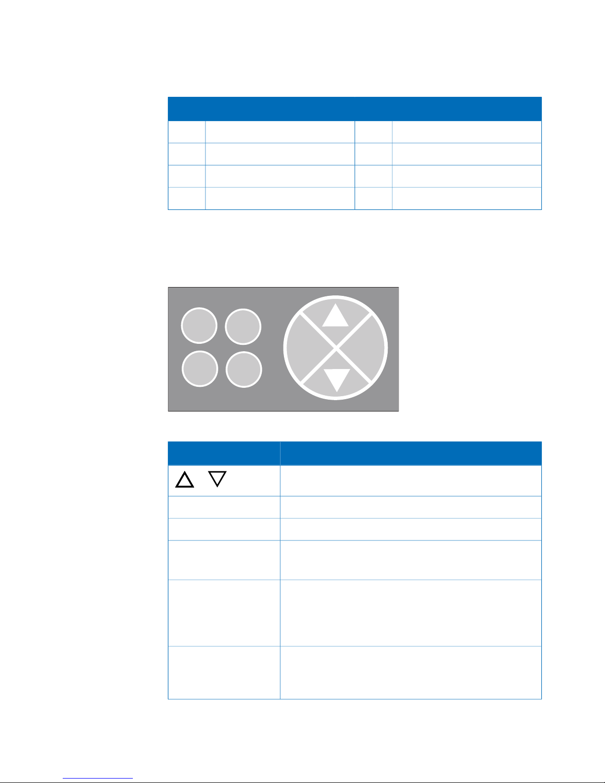
Navigation menu
The system is operated from the push buttons and LCD display at the front panel.
end
OK
Esc
pause
/cont
hold
/cont
feed
tube
Figure 1.2: Push buttons.
DescriptionButton
Find a specific menu option
or
Enter a menu.OK
Return one menu level.Esc
Interrupt method operation before the run is completed.end
Stop manual operation.
Hold method time or volume and the gradient at the current concentration. Pump and fraction collector continue
uninterrupted.
hold /cont
Continue the normal method operation.
Pause all operation without ending the method. All functions, including pump and fraction collector, are stopped.
pause /cont
Continue the normal method operation.
ÄKTAprime plus Operating Instructions 28-9597-89 AC 11
1 Introduction
1.3 Instrument

DescriptionButton
Advance the fraction collector one position.feed tube
Basic flow path
IN
IN
P
M
UV
C
pH
F
W
V2
V1
B
SW
Figure 1.3: Basic flow path.
DescriptionPartStage
Pump P pumps buffer from a buffer container connected to the
buffer valve V1.
P, V11
To form a gradient the switch valve (SW) can be used topull liquid
from buffer container (B).
SW, B2
The mixer (M) mixes the buffers.M3
Sample is applied from the sample loop connected to injection
valve (V2) that has been previously filled manually using a syringe.
V24
From the injection valve, the flow is directed to the column, and
then to the UV, Conductivity, and optional pH monitor.
UV, C, pH5
From the monitors, the flow is directed to the Fraction collector
F or the Waste W.
F, W6
12 ÄKTAprime plus Operating Instructions 28-9597-89 AC
1 Introduction
1.3 Instrument

1.4 Monitoring and evaluation
PrimeView™software
PrimeView isa software thatallows realtime monitoring,evaluation and report generation
on an external computer.
For more information about PrimeViewevaluation systemand instructionsfor installation,
see the PrimeView User Manual supplied.
Paper chart recorder
It is possible to connect a chart recorder to ÄKTAprime plus to get real time monitoring.
For more information see the ÄKTAprime plus User Manual.
1.5 User documentation
In addition to these Operating Instructions, the documentation package supplied with
ÄKTAprime plus also includes product documentation binders containing detailed
specifications and traceability documents.
The mostimportant documentsin the document package withregard to technical aspects
of ÄKTAprime plus are:
System-specific documentation
ContentUser documentation
All instructionsneeded to operate the instrument in a safe way, including brief
system description, installation, and
maintenance.
ÄKTAprime plus Operating Instructions
Detailed systemdescription. Comprehensive user instructions, method creation,
operation, advanced maintenance and
troubleshooting.
ÄKTAprime plus User Manual
Short step-by-stepinstructions forselected applications using the preprogrammed method templates. System
preparation and value table for the
method templates.
ÄKTAprime plus Cue Cards
ÄKTAprime plus Operating Instructions 28-9597-89 AC 13
1 Introduction
1.4 Monitoring and evaluation

ContentUser documentation
Covers the system introduction, step by
step installation, setting-up the run and
evaluation of results.
ÄKTAprime plus training video
Document whereby the manufacturer
ensures that the product satisfies and is
in conformity with the essential requirements of the applicable directives.
EU Declaration of Conformity for
ÄKTAprime plus
Software documentation
Together with each system, the following software documentation is supplied providing
additional information that applies to ÄKTAprime plus, independent of the specific
configuration:
Purpose/ContentsDocument
A completecontrol software packagefor supervision
of ÄKTAprime plus automated liquid chromatography systems.
PrimeView User Manual
Component documentation
Documentation forcomponents produced both by GE and by a third-party are, ifexistent,
also included in the document package.
14 ÄKTAprime plus Operating Instructions 28-9597-89 AC
1 Introduction
1.5 User documentation

2 Safety instructions
About this chapter
This chapter describes safety compliance, safety labels, general safety precautions,
emergency procedures, power failure and recycling of ÄKTAprime plus.
2.1 Safety precautions
Introduction
The ÄKTAprime plus instrument is powered by mains voltage and handles pressurized
liquids that may be hazardous. Before installing, operating or maintaining the system,
you must be aware of the hazards described in this manual. Follow the instructions
provided to avoid personal injury or damage to the equipment.
The safety precautions in this section are grouped into the following categories:
•
General precautions
•
Using flammable liquids
•
Personal protection
•
Installing and moving the instrument
•
System operation
•
Maintenance
General precautions
Always follow these General precautions to avoid injury when using the ÄKTAprime plus
instrument.
WARNING
Do not operate ÄKTAprime plus in any other way than described
in the ÄKTAprime plus and PrimeView manuals. If the equipment
is used in a manner not specified by the manufacturer, the protection provided by the equipment may be impaired.
ÄKTAprime plus Operating Instructions 28-9597-89 AC 15
2 Safety instructions
WARNING
Operation anduser maintenance of the ÄKTAprime plusinstrument
should be performed by properly trained personnel only.
WARNING
Before connecting a column to the ÄKTAprime plus instrument,
read the instructions for use of the column. To avoid exposing the
column to excessive pressure, make sure that the pressure limit is
set to the specified maximum pressure of the column.
WARNING
Do not use any accessories not supplied or recommended by GE.
WARNING
Do not use ÄKTAprime plus if it is not working properly, or if it has
suffered any damage, for example:
•
damage to the power cord or its plug
•
damage caused by dropping the equipment
•
damage caused by splashing liquid onto it
CAUTION
Waste tubesand containersmust be secured and sealed to prevent
accidental spillage.
CAUTION
Make sure that the waste container is dimensioned for maximum
possible volume when the instrument is left unattended.
16 ÄKTAprime plus Operating Instructions 28-9597-89 AC
2 Safety instructions
2.1 Safety precautions
NOTICE
Avoid condensation by letting the unit equilibrate to ambient temperature.
Using flammable liquids
When using flammableliquids withthe ÄKTAprimeplus instrument, followthese precautions to avoid any risk of fire or explosion.
WARNING
Fire Hazard. Before starting the system, make sure that there is
no leakage.
WARNING
A fume hood or similar ventilation system shall be installed when
flammable or noxious substances are used.
Personal protection
WARNING
Always use appropriate Personal ProtectiveEquipment (PPE) during
operation and maintenance of ÄKTAprime plus system.
WARNING
When using hazardous chemical and biological agents, take all
suitable protective measures, such as wearing protective glasses
and gloves resistant to the substances used. Follow local and/or
national regulations for safe operation and maintenance of
ÄKTAprime plus.
ÄKTAprime plus Operating Instructions 28-9597-89 AC 17
2 Safety instructions
2.1 Safety precautions
WARNING
Spread of biological agents. The operatorhas totake all necessary
actions to avoid spreading hazardous biological agents in the
vicinity of the instrument. The facility should comply with the national code of practice for biosafety.
WARNING
High pressure. ÄKTAprime plus operates under high pressure.
Wear protective glasses and other required Personal Protective
Equipment (PPE) at all times.
Installing and moving the
instrument
WARNING
Supply voltage. Make sure that the supply voltage at the wall
outlet corresponds to the marking on the instrument, before connecting the power cord.
WARNING
ÄKTAprime plus must always be connected to a grounded power
outlet.
WARNING
Power cord. Only use power cords with approved plugs delivered
or approved by GE Healthcare.
18 ÄKTAprime plus Operating Instructions 28-9597-89 AC
2 Safety instructions
2.1 Safety precautions

WARNING
Access to power switch and power cord with plug. Do not block
access to the power switch and power cord. The power switch
must always be easy to access. The power cord with plug must
always be easy to disconnect.
WARNING
Do not block the ventilation inlets or outlets on the system.
WARNING
Installing the computer. The computer should be installed and
used according to the instructions provided by the manufacturer
of the computer.
NOTICE
Any computerused with the equipment shall comply withIEC 60950
and beinstalled andused according to the manufacturer's instructions.
NOTICE
Disconnect power. To preventequipment damage,always discon-
nect power from the ÄKTAprime plus instrument before an instrument module is removed or installed, or a cable is connected or
disconnected.
System operation
WARNING
Hazardous chemicals during run. When using hazardous chemi-
cals, run System CIP and Column CIP to flush the entire system
tubing with distilled water, before service and maintenance.
ÄKTAprime plus Operating Instructions 28-9597-89 AC 19
2 Safety instructions
2.1 Safety precautions

WARNING
Hazardous biological agents during run. When using hazardous
biological agents, run System CIP and Column CIP to flush the
entire system tubing with bacteriostatic solution (e.g. NaOH) followed by a neutral buffer and finally distilled water, before service
and maintenance.
WARNING
There must always be a sample loop connected to ports 2 and 6
of the injection valve. This is to prevent liquid spraying out of the
ports when switching the valve. This is especially dangerous if
hazardous chemicals are used.
CAUTION
Hazardous chemicals in UV flow cell. Make sure that the entire
flow cell has been flushed thoroughly with bacteriostatic solution,
for example NaOH, and distilled water, before service and maintenance.
NOTICE
If the ÄKTAprime plus is kept in a cold room, cold cabinet or similar,
keep the system switched on in order to minimize the risk of condensation. (The UV lamp can be turned off to save lamp life time
when the system is not in use.)
NOTICE
When switchingoff thecold cabinet, makesure that you also switch
off the ÄKTAprime plus system and leave the door to the cold
cabinet open to avoid overheating.
20 ÄKTAprime plus Operating Instructions 28-9597-89 AC
2 Safety instructions
2.1 Safety precautions

Maintenance
WARNING
Electrical shock hazard. All repairs should be done by service
personnel authorized by GE Healthcare. Do not open any covers
or replace parts unless specifically stated in the user documentation.
WARNING
Disconnect power. Always disconnect power from the instrument
before replacing any component on the instrument, unless stated
otherwise in the user documentation.
WARNING
Hazardous chemicals duringmaintenance. When using hazardous
chemicals for system or column cleaning, wash the system or
columns with a neutral solution in the last phase or step.
WARNING
Do not perform any type of maintenance work while the system is
powered electrically or when the piping system is pressurized. Note
that the piping system can be pressurized even when the system
is closed down.
WARNING
Only spare parts and accessories that are approved or supplied
by GE may be used for maintaining or servicing ÄKTAprime plus.
WARNING
Make sure thatthe piping system is completelyleakage free before
performing any CIP on the system.
ÄKTAprime plus Operating Instructions 28-9597-89 AC 21
2 Safety instructions
2.1 Safety precautions

WARNING
NaOH is corrosive and therefore dangerous to health. When using
hazardous chemicals, avoid spillage and wear protective glasses
and other suitable Personal Protective Equipment (PPE).
WARNING
After assembly, the piping system must be tested for leakage at
maximum pressure for continued protection against injury risks
due to fluid jets, burst pipes or explosive atmosphere.
WARNING
Before disassembly, check that there is no pressure in the piping
system.
WARNING
Decontaminate the equipment before decommissioning to ensure
that hazardous residues are removed.
CAUTION
Fire hazard. Follow instructions in ÄKTAprime plus Operating
Instructions for correct installation of a new UV-lamp. If the lamp
is not installed properly it may be overheated and cause a fire
hazard.
CAUTION
The systemuses high intensity ultra-violet light. Do not removethe
UV lamp while the system is running. Before replacing a UV lamp,
ensure that the lamp is disconnected to prevent injury to eyes.
If the mercury lamp is broken, make sure that all mercury is removed anddisposed according tonational andlocal environmental
regulations.
22 ÄKTAprime plus Operating Instructions 28-9597-89 AC
2 Safety instructions
2.1 Safety precautions

NOTICE
Cleaning. Keep the instrument dry and clean. Wipe regularly with
a softdamp tissue and, if necessary, a mildcleaning agent. Let the
instrument dry completely before use.
2.2 Labels
In this section
This sectiondescribes theinstrument labels and labels concerning hazardous substances
that are attached to the ÄKTAprime plus instrument. For information about marking of
the computer equipment, refer to the manufacturer’s instructions.
Labels on the instrument
The illustration below shows an example of the identification label that is attached to
ÄKTAprime plus.
ÄKTAprime plus Operating Instructions 28-9597-89 AC 23
2 Safety instructions
2.1 Safety precautions

Symbols used in instrument
labels
MeaningLabel
Warning! Read the user documentation before usingthe equipment.
Do not open any covers or replace parts unless specifically stated in
the user documentation.
The equipment complies with the requirements for electromagnetic
compliance (EMC) in Australia and New Zealand.
The equipment complies with applicable European directives.
This symbol indicates that ÄKTAprime plus has been certified by a
Nationally Recognized Testing Laboratory (NRTL). NRTL means an
organization, which isrecognized by theUS Occupational Safetyand
Health Administration (OSHA) as meeting the legal requirements of
Title 29 of the Code of Federal Regulations (29 CFR), Part 1910.7.
Labels concerning hazardous
substances
MeaningLabel
This symbol indicates that the waste of electrical and electronic equipment must not be disposed as unsorted municipal waste and must be
collected separately. Please contact anauthorized representative of the
manufacturer for information concerning the decommissioning of
equipment.
24 ÄKTAprime plus Operating Instructions 28-9597-89 AC
2 Safety instructions
2.2 Labels

MeaningLabel
This symbol indicates that the product contains hazardous materials in
excess ofthe limitsestablished by the Chinesestandard SJ/T11363-2006
Requirements for ConcentrationLimits forCertain HazardousSubstances
in Electronics.
2.3 Emergency procedures
In this section
This section describeshow to do an emergency shutdownof the ÄKTAprime plus system.
The section also describes the result in the event of power failure.
Emergency shutdown
In an emergency situation, do as follows to stop the run:
ActionStep
To pause the run without ending the method, pressthe Pausebutton located
at the instrument front.
1
If required, switch off power to the instrument by pressing the Main power
switch to the 0 position. The run is interrupted immediately.
2
Power failure
The result of a power failure depends on which unit that is affected.
will result in...Power failure to...
•
The run is interrupted immediately, in an undefined
state
•
The data collected up to the time of the power failure
is available in PrimeView
ÄKTAprime plus
•
The PrimeViewcomputer shuts down in an undefined
state
•
The run continues, but data cannot be saved in
PrimeView.
Computer
ÄKTAprime plus Operating Instructions 28-9597-89 AC 25
2 Safety instructions
2.2 Labels

2.4 Recycling information
Decontamination
ÄKTAprime plus shall be decontaminated before decommissioning and all local regulations shall be followed with regard to scrapping of the equipment.
Disposal, general instructions
When taking ÄKTAprime plus out of service, the different materials must be separated
and recycled according to national and local environmental regulations.
Recycling of hazardous
substances
ÄKTAprime plus contains hazardous substances. Detailed information is available from
your GE representative.
Disposal of electrical
components
Waste ofelectrical andelectronic equipment must not be disposed as unsorted municipal
waste and must be collected separately. Please contact an authorized representative
of the manufacturer for information concerning the decommissioning of equipment.
26 ÄKTAprime plus Operating Instructions 28-9597-89 AC
2 Safety instructions
2.4 Recycling information

2.5 Declaration of Hazardous Substances (DoHS)
根据SJ/T11364-2006《电子信息产品污染控制标识要求》特提供如下有关污染 控制方面的信息。
The following product pollution control information is provided according to SJ/T11364-2006 Marking
for Control of Pollution caused by Electronic Information Products.
电子信息产品污染控制标志说明
Explanation of Pollution Control Label
该标志表明本产品含有超过SJ/T11363-2006《电子信息产品中有毒有害物质的限
量要求》中限量的有毒有害物质。标志中的数字为本产品的环保使用期,表明本
产品在正常使用的条件下,有毒有害物质不会发生外泄或突变,用户使用本产品
不会对环境造成严重污染或对其人身、财产造成严重损害的期限。单位为年。
为保证所申明的环保使用期限,应按产品手册中所规定的环境条件和方法进行正
常使用,并严格遵守产品维修手册中规定的期维修和保养要求。
产品中的消耗件和某些零部件可能有其单独的环保使用期限标志,并且其环保使
用期限有可能比整个产品本身的环保使用期限短。应到期按产品维修程序更换那
些消耗件和零部件,以保证所申明的整个产品的环保使用期限。
本产品在使用寿命结束时不可作为普通生活垃圾处理,应被单独收集妥善处理。
This symbolindicates theproduct contains hazardous materials in excess of the limits
established bythe Chinese standard SJ/T11363-2006 Requirements for Concentration
Limits for Certain Hazardous Substances in Electronic Information Products. The
number in the symbol is the Environment-friendly Use Period (EFUP), which indicates
the period during which the toxic or hazardous substances or elements contained in
electronic information products will not leak or mutate under normal operating conditions so that the use of such electronic information products will not result in any
severe environmental pollution, any bodily injury or damage to any assets. The unit
of the period is “Year”.
In order to maintain the declared EFUP, the product shall be operated normally according to the instructions and environmental conditions as defined in the product
manual, and periodic maintenance schedules specified in Product Maintenance Procedures shall be followed strictly.
Consumables or certain parts may have their own labelwith an EFUPvalue less than
the product. Periodic replacement of those consumables or parts to maintain the
declared EFUP shall be done in accordancewith theProduct Maintenance Procedures.
This product must not be disposed of as unsorted municipal waste, and must be
collected separately and handled properly after decommissioning.
ÄKTAprime plus Operating Instructions 28-9597-89 AC 27
2 Safety instructions
2.5 Declaration of Hazardous Substances (DoHS)

有毒有害物质或元素的名称及含量
Name and Concentration of Hazardous Substances
产品中有毒有害物质或元素的名称及含量
Table of Hazardous Substances’ Name and Concentration
有毒有害物质或元素
Hazardous substance
部件名称
Component name
多溴二苯醚
PBDE
多溴联苯
PBB
六价铬
Cr6+
镉
Cd
汞
Hg
铅
Pb
00000X11-0013-13
0:
表示该有毒有害物质在该部件所有均质材料中的含量均在SJ/T11363-2006 标准规定的限
量要 求以下
X:
表示该有毒有害物质至少在该部件的某一均质材料中的含量超出SJ/T11363-2006 标准规
定的限量要求
•
此表所列数据为发布时所能获得的最佳信息
0:
Indicates that this toxic or hazardous substance contained in all of the homogeneous materials for this part is below the limit requirement in SJ/T11363-2006.
X:
Indicates that this toxic or hazardous substance contained in at least one of the homogeneous materials used for this part is above the limit requirement in SJ/T11363-2006.
•
Data listed in the table represents best information available at the time of publication.
28 ÄKTAprime plus Operating Instructions 28-9597-89 AC
2 Safety instructions
2.5 Declaration of Hazardous Substances (DoHS)

3 Installation
ÄKTAprime plus is delivered in protective packing material and shall be unpacked with
great care.
Any equipment connected to ÄKTAprime plus must fulfill applicable standards and local
regulations.
A video describing the installationprocess, is supplied with each ÄKTAprimeplus system.
For detailed information on Installation, see ÄKTAprime plus User Manual.
3.1 Site requirements
RequirementParameter
Indoor useOperation site
Maximum 2000 mAltitude
Stable laboratory bench e.g. 120 × 80 cmPlacement
100-120/220-240 V AC ±10%, 50-60 HzElectrical power
Overvoltage category IITransient overvoltages
4°C to 40°CAmbient temperature
20% to 95%, non-condensingHumidity
84 to 106 kPa (840 to 1060 mbar)Atmospheric pressure
2Pollution degree
WARNING
Do not block the ventilation inlets or outlets on the system.
3.2 Transport
The equipment can be transported on a trolley capable of supporting at least 20 kg.
ÄKTAprime plus Operating Instructions 28-9597-89 AC 29
3 Installation

NOTICE
Lift the instrument in the upright position. Do not use the fractionation arm as a lifting handle.
Before moving the system:
•
disconnect all cables and tubing connected to peripheral components and liquid
containers.
•
remove any loose items from the top of the instrument.
•
grasp the instrument firmly by placing the fingers under the base of the main unit
and lift.
For more information on transport, see ÄKTAprime plus User Manual.
3.3 Unpacking
Check for damage
Check the equipment for damage before starting assembly and installation. There are
no loose parts in the transport box.All partsare either mountedon thesystem or located
in the accessory kit box. If any damage is found, document the damage, and contact
your local GE representative.
Unpack the system
Remove straps and packing material. Then set the equipment upright before starting
installation.
3.4 Connections
Communication
Connect thesystem according to the electrical drawings in Electrical and communication
connections, on page 10.
30 ÄKTAprime plus Operating Instructions 28-9597-89 AC
3 Installation
3.2 Transport

Flow path
All parts and tubing are mounted on the system at delivery.
Connect a waste tube, buffer and sample bottles, and optional accessories.
Electrical power
Connect the power cord to a grounded power outlet specified in Section 3.1 Site require-
ments, on page 29.
3.5 Spare parts and accessories
For correct up to date information on spare parts and accessories visit:
www.gelifesciences.com/AKTA
ÄKTAprime plus Operating Instructions 28-9597-89 AC 31
3 Installation
3.4 Connections

4 Operation
About this chapter
This chapter provides instructions for the use of ÄKTAprime plus.
4.1 Operation overview
Workflow
The typical workflow in ÄKTAprime plus, after turning on the system, can be divided into
a number of steps.
SectionActionStep
Section 4.3 Preparations before start, on page 33Prepare the system for a run1
Section 4.4 Performing a run, on page 38Start a run using a method2
Viewing the run, on page 39During a run - view and change parame-
ters
3
Section 4.5 Procedures after a run, on page 40Procedures after a run4
See PrimeView user documentation.Evaluate the results5
Liquid flow path
See Appendix A Connection diagram - Liquid flow path, on page 64 for an illustration of
the liquid flow path in ÄKTAprime plus.
4.2 Starting the instrument
If the system is not already turned on:
1
Turn on the system using the Power switch at the rear panel. The system now performs a self-test.
2
First thesystem nameand software versionnumber are displayed. Several messages
are then shown during the self-test. If an error is detected during the self-test, an
error message is shown.
3
All parameters are automatically set to factory default values during the self-test.
32 ÄKTAprime plus Operating Instructions 28-9597-89 AC
4 Operation

4
The self-test takes about 30–40 seconds. When the test is completed, the display
shows the Templates menu.
The system can be used for most applications after 15 min of lamp warm-up
but the full specifications are not obtained until after 1 hour.
Note:
4.3 Preparations before start
Buffer preparation
Prepare buffers according to ÄKTAprime plus cue cards.
Sample preparation
1
Adjust the sample composition to the binding buffer by:
•
diluting the sample in binding buffer, or
•
buffer exchange using HiTrap™ Desalting or HiPrep™ 26/10 Desalting column.
2
Filter the sample through a 0.45 µm filter.
Purification setup
Removing storage solution from the flow path
At delivery and during storage, the flow path is filled with 20% ethanol. This should be
removed before continuing the setup.
Do not use buffer with high salt concentration to flush out the ethanol. It might
cause too high backpressure.
Note:
To flush out the ethanol using deionized water:
1
Put the inlet tubing A1–A8 that is used and B in deionized water.
At delivery, only A1 and B are installed.
Note:
2
Put all waste capillaries, W1–W3, in waste.
3
Select Templates in the main menu using the and buttons and press OK.
4
Select Application Template and press OK.
5
Select System Wash Method and press OK.
ÄKTAprime plus Operating Instructions 28-9597-89 AC 33
4 Operation
4.2 Starting the instrument

6
Choose to wash the A2–A8 inlet tubing that is used by pressing OK at those cursor
positions. A1 and B will always be washed.
At delivery, only A1 and B are installed.
Note:
7
Scroll to OK and press the OK button.
8
Press OK to start the method.
9
When the method is finished, replace the first collection tube. It will contain a small
amount of water after the system wash.
Purging the pump and inlet tubing
If there are large amounts of air in the tubing or if you suspect air in the pump, use the
Purge kit to purge the flow path. Air bubbles that still are trapped in the pump (causing
increased pulsation) can be removedby flushing100% ethanolthrough thepump. These
two procedures are described in the following two sections.
Purging the flow path using the Purge kit:
1
Remove the stop plug from the pump.
2
Connect the Purge kit to the pump.
1
2
3
4
5
6
7
8
9
10
ml
3
Put the used inlet tubing in the appropriate buffers.
4
Run the pump at 0.1 ml/min.
Filling inlet tubing A1–A8:
1
Go to Set Buffer Valve using the arrow buttons.
2
Set the chosen A inlet and press OK. The valve switches to the selected port .
3
Draw buffer with the purge syringe until liquid enters the syringe.
4
Repeat step 1–3 until all chosen A inlet tubing is filled.
Filling inlet tubing B:
1
Go to Set Concentration %B and set the concentration to 100%.
34 ÄKTAprime plus Operating Instructions 28-9597-89 AC
4 Operation
4.3 Preparations before start

2
Press OK. The switch valve turns to the inlet B port.
3
Draw buffer with the purge syringe until liquid enters the syringe.
4
Replace the purge tubing with the stop plug.
5
Stop the pump by pressing end and then OK.
Flushing the pump with 100% ethanol:
1
Put inlet tubing A1 in deionized water.
2
Run the pump at 40 ml/min for 1 min and press pause/cont.
3
Move inlet tubing A1 to 100% ethanol
4
Press pause/cont, run the pump for 10–20 s and press pause/cont.
5
Set the flow rate to 5 ml/min using the arrow buttons.
6
Press pause/cont, run the pump for at least 30 s and press pause/cont.
7
Move inlet tubing A1 to deionized water.
8
Press pause/cont and run the pump for 1 min.
9
Finish by pressing end and then OK.
Preparing the tubing and column
1
Put inlet tubing A1 in the binding buffer.
2
Put inlet tubing B in the elution buffer.
3
Put the three waste capillaries (brown color) from port 4 and 5 on the injection valve
and port NO on the fraction collector valve in waste.
4
Connect a column, for example a HisTrap™ HP 1 ml column, between port 1 on the
injection valve and the upper port of the UV flow cell. Use a suitable length of PEEK
tubing and 1/16" male connectors.
1
2
3
4
ÄKTAprime plus Operating Instructions 28-9597-89 AC 35
4 Operation
4.3 Preparations before start

DescriptionNo.DescriptionNo.
HisTrap column3Tubing from injection valve1
UV cell41/16" male connector2
Other unions and connectors might be required for other columns.
Note:
Preparing the fraction collector
1
Fill the fraction collector rack with, for example, 18 mm tubes (minimum 40 pcs.).
2
Adjust the height of the delivery arm using the lock knob (1) so that the bottom of
the tubesensor (2)is about5 mmbelow the top of the tubes. The tubes should always
be below the horizontal mark on the tube sensor.
5 mm
1
2
3
If necessary, adjust the length of the tubing exposed according to the sequence
shown below (the hole in the delivery arm used in step 3 and 4 is only used for adjusting the tubing length).
5.
3.
4.
1.
2.
36 ÄKTAprime plus Operating Instructions 28-9597-89 AC
4 Operation
4.3 Preparations before start

4
Check that the tube sensor (1) is in the correct position for the tube size. The eluent
tubing should be over the center of the collection tube. Use the red sensor control
knob (2) to position the tube holder (3).
2
1
3
5
Rotate the rack by hand until the rear half of the tube sensor rests against the first
tube.
6
Press feed tube on the front panel (see Figure1.2). The bowl moves to the correct
position to collect the first fraction in the first tube.
7
Make sure that drop synchronization is turned on.
Drop synchronization can NOT be used at flowrates above 3 ml/min.
Note:
Preparing the monitors
1
Check the UV lamp filter position and the lamp position.
2
Calibrate the pH electrode (optional).
See ÄKTAprime plus User Manual for more information.
Filling the buffer inlet tubing
When running an application templates, the buffer inlet tubing will automatically be
filled with buffer.
For other applications, fill the inlet tubing manually with buffer as described in the
ÄKTAprime plus User Manual.
Filling the sample loop
Using an injection fill port
ÄKTAprime plus Operating Instructions 28-9597-89 AC 37
4 Operation
4.3 Preparations before start

1
Connect a sample loop between port 2 and 6 on the injection valve. Make sure that
the sample loop is large enough for your sample.
2
Connect a luer female/1/16" male union to port 3.
3
Fill a syringe with five loop volumes of deionized water or binding buffer.
4
Fit the syringe in the Luer union (1) and carefully inject the buffer.
3
1
5
Remove the syringe and fill it with at least two loop volumes of the sample.
6
Carefully inject the sample into the sample loop. Do NOT remove the syringe after
the injection because the loop might otherwise be emptied due to self-drainage or
air may be introduced in the flow path.
4.4 Performing a run
Selecting template and starting
the run
1
Select Templates in the main menu and press OK.
2
Select Application Template and press OK.
3
Select theappropriate template, for example His Tag PurificationHisTrap, and press
OK.
4
Set the sample volume and press OK.
5
Press OK to start the purification run.
38 ÄKTAprime plus Operating Instructions 28-9597-89 AC
4 Operation
4.3 Preparations before start

Viewing the run
When the pump starts running, the progress of the run can be viewed in the two panes
in PrimeView.
•
The Curves pane displays monitor signal values graphically.
•
The Logbook pane displays all actions (e.g. method start and end, base instructions
and method instructions)and unexpectedconditions (e.g. warningsand alarms). The
log is saved in the result file.
Selecting curves to be displayed
1
In PrimeView module, select View:Properties.
2
In the Properties dialog, click the Curves tab.
3
In the Display curves list, select the curves you want to display.
4
Click OK.
For more information on customizing the view panes, see PrimeView User Manual.
ÄKTAprime plus Operating Instructions 28-9597-89 AC 39
4 Operation
4.4 Performing a run

Ending the run
Press OK at the Method Complete prompt. This will cause all valves to return to their
default positions.
To stop the run on a system before it is finished:
1
Press the end button.
2
Select yes and press OK.
Error indication
When a warning or an alarm is issued from a system, an error code is displayed. See
ÄKTAprime plus User Manual for guidance.
Evaluate the results
PrimeView Evaluation module provides facilities for the presentation and evaluation of
separation results.
To start PrimeView Evaluation module, click PrimeView Evaluation iconon theWindows
desktop.
See ÄKTAprime plus User Manual and PrimeView User Manual for how to evaluate the
results.
4.5 Procedures after a run
Cleaning after a run
NOTICE
Do not allow solutions which contain dissolved salts, proteins or
other solid solutes to dry out in the UV flow cell.
40 ÄKTAprime plus Operating Instructions 28-9597-89 AC
4 Operation
4.4 Performing a run

NOTICE
Do not allow particles to enter the UV flow cell as damage to the
flow cell might occur.
Buffers notcontaining anysalt can be left in the system for ashort time after a run, even
overnight (not in the pH electrode, see instructions below).
NOTICE
If a buffer containing salt has been used, the flow path must be
flushed with deionized water.
To flush the flow path:
1
Fill a syringe with five times the sample loop volume of deionized water.
2
Rinse the sample loop by injecting the water through the fill port on the injection
valve.
3
Put all used inlet tubings in water.
4
In theTemplates menu, selectApplication Template and then System Wash Method.
5
Select the used inlet ports. Inlets A1 and B will always be washed.
6
Press OK to start the method. The system flow path is now automatically flushed.
For informationon cleaningand long-termstorage, seeSection 5.3 Cleaning, on page 45
and Section 5.7 Storage, on page 48.
ÄKTAprime plus Operating Instructions 28-9597-89 AC 41
4 Operation
4.5 Procedures after a run

5 Maintenance
About this chapter
This chapter provides instructions for routine component maintenance and a maintenance schedule.
5.1 General
Regular maintenanceis important for safeand trouble-free operationof yourinstrument.
The usershould perform daily andmonthly maintenance. Preventivemaintenance should
be performed on a yearly basis by qualified service personnel.
For maintenance of a specific component, carefully read the component manual and
follow the instructions.
WARNING
Electrical shock hazard. All repairs should be done by service
personnel authorized by GE Healthcare. Do not open any covers
or replace parts unless specifically stated in the user documentation.
WARNING
Disconnect power. Always disconnect power from the instrument
before replacing any component on the instrument, unless stated
otherwise in the user documentation.
WARNING
Hazardous chemicals duringmaintenance. When using hazardous
chemicals for system or column cleaning, wash the system or
columns with a neutral solution in the last phase or step.
42 ÄKTAprime plus Operating Instructions 28-9597-89 AC
5 Maintenance

WARNING
Do not perform any type of maintenance work while the system is
powered electrically or when the piping system is pressurized. Note
that the piping system can be pressurized even when the system
is closed down.
WARNING
When using hazardous chemical and biological agents, take all
suitable protective measures, such as wearing protective glasses
and gloves resistant to the substances used. Follow local and/or
national regulations for safe operation and maintenance of
ÄKTAprime plus.
CAUTION
Fire hazard. Follow instructions in ÄKTAprime plus Operating
Instructions for correct installation of a new UV-lamp. If the lamp
is not installed properly it may be overheated and cause a fire
hazard.
NOTICE
Cleaning. Keep the instrument dry and clean. Wipe regularly with
a softdamp tissue and, if necessary, a mildcleaning agent. Let the
instrument dry completely before use.
5.2 User maintenance schedule
Table 5.1 provides a guide to maintenance operations and intervals at which these op-
erations should be performed by the user. The user is however responsible for deciding
the type of operations and length of intervals necessary to maintain system function
and safety.
ÄKTAprime plus Operating Instructions 28-9597-89 AC 43
5 Maintenance
5.1 General

Table 5.1: User maintenance schedule
Instructions/referenceActionInterval
Visually inspect the system for leaks.Leak inspectionDaily
1
For cleaning the flow path,see Cleaning-In-
Place, on page 45.
2
For leaving the system for a few days, see
Section 5.7 Storage, on page 48.
Wash thesystem flow
path
Calibrate thepH electrode (if applicable) according to Monitor pH/C-900 User Manual.
Calibrate pHelectrode
(optional)
Check theinlet filters visually and replace them
if necessary.
Check inlet filtersWeekly
Replace the on-line filter.Replace on-line filter
(if applicable)
Check thatflow restrictor generates the following back-pressure:
Flow restrictorMonthly
FR-904: 0.4 ±0.05 MPa
Check the back-pressure as follows:
1
Disconnect the flow restrictor.
2
Connect a tubing (approx. 1 m, i.d. 1 mm)
to the waste port (port 5) on the injection
valve. Set the injection valve manually to
Waste position.Put theopen endin awaste
container.
3
Run the pump manually at 10 ml/min with
water. Note the back-pressure (Bp1) on the
pump display, or in the Run Data window.
4
Set the system to Pause and connect the
flow restrictor tothe openend of thetubing
(observe theIN marking).Put theflow restrictor in the waste container.
5
Press Continue so that the pump run at 10
ml/min with water. Note the back-pressure
(Bp2) on the pump display, or in the Run
Data window.
6
Calculate the back-pressure generated by
the flow restrictor (Bp2-Bp1). Replace it if it
is not within limit.
44 ÄKTAprime plus Operating Instructions 28-9597-89 AC
5 Maintenance
5.2 User maintenance schedule

Instructions/referenceActionInterval
Check for external or internal leakage. Replace
channel plate and distribution plate yearly or
when required. Refer to the relevant valve instruction sheet.
Valve inspectionYearly
5.3 Cleaning
Cleaning before planned
maintenance/service
To ensure the protection and safety of service personnel, all equipment and work areas
must beclean and free of any hazardous contaminants before a Service Engineerstarts
maintenance work.
Please complete the checklist in the On Site Service Health and Safety Declaration Form
or the Health and Safety Declaration Form for Product Return or Servicing, depending on
whether theinstrument isgoing tobe serviced on site or returned for service, respectively.
Copy theform you need from Section 7.4 Health and Safety Declaration Form, on page61
or print it from the PDF file available on the User Documentation CD.
Cleaning-In-Place
All components in the system are designed for ease of CIP.
After repeated separation cycles, contaminating material might progressively build up
in the system and on the column. This material may not have been removed by the
cleaning step described above. The nature and degree of contamination depends on
the sampleand thechromatographic conditions employed. These should be considered
when designing a cleaning protocol.
Routine cleaning should be performed at intervals aimed at prevention rather than
cleaning the system from growth or contamination.
WARNING
Make sure thatthe piping system is completelyleakage free before
performing any CIP on the system.
ÄKTAprime plus Operating Instructions 28-9597-89 AC 45
5 Maintenance
5.2 User maintenance schedule

Make sure that the process control method for cleaning flushes all possible flow paths
in the system. After cleaning, rinse the entire system with water or suitable liquid until
the piping/tubing system is completelyfree from theCIP solution(monitors in the system
can be used as detectors). Do not leave NaOH or other cleaning agents in the system
for long periods.
WARNING
Hazardous chemicals duringmaintenance. When using hazardous
chemicals for system or column cleaning, wash the system or
columns with a neutral solution in the last phase or step.
WARNING
NaOH is corrosive and therefore dangerous to health. When using
hazardous chemicals, avoid spillage and wear protective glasses
and other suitable Personal Protective Equipment (PPE).
See also Section 5.7 Storage, on page 48.
5.4 Component maintenance
Maintenance and preventivereplacement of parts ofthe major components are described
in the respective manuals included in the system documentation.
The system documentation also includes a spare part list to be used to find common
spare parts and their code numbers for ordering. This list can also be found online at
www.gelifesciences.com/AKTA.
5.5 Disassembly and assembly of components and consumables
The operator must carefully read and understand the instructions supplied for each
component before disassembly and assembly of the component. When replacing consumables, suchas tubingand tubingconnectors, allneccessary safetyprecautions must
be taken. Contact your local GE Healthcare representative if further information or help
is needed.
WARNING
Disconnect power. Always disconnect power from the instrument
before replacing any component on the instrument, unless stated
otherwise in the user documentation.
46 ÄKTAprime plus Operating Instructions 28-9597-89 AC
5 Maintenance
5.3 Cleaning

WARNING
Before disassembly, check that there is no pressure in the piping
system.
WARNING
After assembly, the piping system must be tested for leakage at
maximum pressure for continued protection against injury risks
due to fluid jets, burst pipes or explosive atmosphere.
5.6 Calibration
The table below lists the type and frequency of calibrations that can be done on the instrument. Refer toPrimeView userdocumentation andto theindividual componentUser
Manuals and Instructions for descriptions of how to perform these calibrations. The
calibrations are performed from PrimeView by selecting System:Calibrate in System
Control.
How oftenComponent
Every day.pH monitor (if applicable)
When required.Pump (if applicable)
When required.Pressure reading
Only necessary if specific conductivity with high
accuracy is measured (Cond_Calib).
Cell constantConductivity
flow cell
Must be done when changing the conductivity
flow cell (Temp).
Temperature
Must be done when changing the conductivity
flow cell (Cond_Cell).
Entering a
new cell constant
ÄKTAprime plus Operating Instructions 28-9597-89 AC 47
5 Maintenance
5.5 Disassembly and assembly of components and consumables

5.7 Storage
General recommendation
For storage, the system must first be cleaned as described in Cleaning-In-Place, on
page 45. After cleaning, the system must be filled with 0.01 M NaOH or 20% ethanol
solution.
Columns and media shall be stored according to their respective instructions.
Storage conditions
The following conditions shall be maintained while the system is in storage:
•
Temperature: 2°C to 30°C (preferably room temperature)
•
Relative humidity: 0% to 95%, non-condensing (preferably low humidity).
After storage,clean thesystem, calibrateall monitors, and perform a leakage test before
using the system.
48 ÄKTAprime plus Operating Instructions 28-9597-89 AC
5 Maintenance
5.7 Storage

6 Troubleshooting
6.1 UV curve problems
Corrective actionPossible causeError symptom
Clean the system. Make sure air is
removed.
Dirt or residues in the
flow path from previous runs. Air in the
eluents.
Ghost peak
Clean the column according to the
column instructions.
Residue in the column
from previous runs
Check the mixer function by placing a stirrer bar on top ofthe mixer
housing. The stirrer bar should rotate when the system is in Run
mode. Themixer function can also
be checked by running the installation test.
Incorrect mixer function
Clean the UV cell by flushing
Decon™ 90, Deconex™ 11 or
equivalent.
Dirty UV cellNoisy UV-signal, sig-
nal drift or instability
Check if the signal is still noisywith
water.
Impure buffer
Purge the pump according to
Pump User Manual. Run a system
wash with buffer.
Air in the pump or in
the UV cell
ÄKTAprime plus Operating Instructions 28-9597-89 AC 49
6 Troubleshooting

Corrective actionPossible causeError symptom
Check thelamp run time according
to and replace if necessary. Refer
to ÄKTAprime plus User Manual.
Aging UV lampLow sensitivity
Check that the lamp position and
the filter position are both set to
the wavelength tobe used,280 nm
or 254nm. Referto ÄKTAprime plus
User Manual.
UV lamp in wrong position
Calculate thetheoretical extinction
coefficient of the protein. If it is zero or very low at 280 nm, the protein cannot be detected.
The theoretical extinction coefficient too
low
6.2 Conductivity curve problems
Corrective actionPossible causeError symptom
Check the flow restrictor after the
flow cell.
Air in the pump or the
flow cell
Baseline drift or noisy
signal
Tighten the clamps. If necessary,
replace the clamps.
Leaking tubeconnections
Check the mixer function by placing a stirrer bar on top ofthe mixer
housing. The stirrer bar should rotate when the system is in Run
mode. Themixer function can also
be checked by running the installation test.
Incorrect mixer function
Clean the conductivity cell by
flushing 1M NaOH or 20% ethanol.
Dirty conductivity cell
Equilibrate the column. If necessary, clean the column using a
method plan for column cleaning.
Column notequilibrated
Clean the flow cell according to
procedure in MonitorUser Manual.
Dirty flow cellConductivity measurement with the same
buffer appears to decrease over time
Use a temperature compensation
factor. See Monitor User Manual.
Decrease in ambient
temperature
50 ÄKTAprime plus Operating Instructions 28-9597-89 AC
6 Troubleshooting
6.1 UV curve problems

Corrective actionPossible causeError symptom
Check that the pump is operating
and is programmed correctly.
Incorrect pump function
Waves on the gradient
Check that the mixing chamber is
free from dirt or particles.
Dirty mixing chamber
Change to a larger mixing chamber volume if necessary.
Insufficient mixing
chamber volume
Check the motor operation. Place
a hand on the mixer and start it by
starting the pump at a low flow
rate. You shouldboth hearand feel
the mixer motor and stirrer when
they are spinning.
Incorrect motor function
Check for loose tubing connections. Use the flow restrictor.
Air in the flow cellGhost peaks appear
in the gradient profile
Wash the tubing and check pump
is operating properly.
Dirty tubingUnlinear gradients or
slow response to %B
changes
Change to smaller mixer volume.Incorrect mixer vol-
ume
ÄKTAprime plus Operating Instructions 28-9597-89 AC 51
6 Troubleshooting
6.2 Conductivity curve problems

Corrective actionPossible causeError symptom
Check that the conductivity flow
cell cable is connected properly.
Loose connection of
conductivity flow cable
Incorrect or unstable
reading
Check that the pump and valves
operate correctly.
Incorrect pump and
valves function
If temperature compensation is
being used,check that the temperature sensor is calibrated,and that
the correct temperature compensation factor is in use.
Incorrect temperature
compensation factor
Check thatthe columnis equilibrated. If necessary clean the column.
Dirty or incorrectly
equilibrated column
Check the operation of the mixer.
The mixer function is checked by
placing a stirrer bar on top of the
mixer housing. The stirrer bar
should rotate when the system is
in Run mode. The mixer function
can also be checked by running
the installation test.
Incorrect mixer function
6.3 pH curve problems
Corrective actionPossible causeError symptom
Check that the electrode cable is
connected properly.
Faulty electrode connection
No response to pH
changes
The electrode glass membrane
may becracked. Replacethe electrode.
Damaged electrode
Check that the pH monitor is correctly connected according to the
ÄKTAprime plus User Manual.
Incorrectly connected
pH monitor
Clean thepH electrode as detailed
in Monitor pH/C-900 User Manual.
Dirty pH electrodeSmall response to pH
changes
If theproblem remains, replacethe
pH electrode.
52 ÄKTAprime plus Operating Instructions 28-9597-89 AC
6 Troubleshooting
6.2 Conductivity curve problems

Corrective actionPossible causeError symptom
Check the electrode glass membrane. If it is contaminated, clean
the electrode following the instructions in Monitor pH/C-900 User
Manual.
Contaminated elec-
trode glass mem-
brane
Slow pH response or
Calibration impossible
If themembrane hasdried out, the
electrode may be restored by
soaking it in buffer overnight.
Membrane has dried
out
ÄKTAprime plus Operating Instructions 28-9597-89 AC 53
6 Troubleshooting
6.3 pH curve problems

Corrective actionPossible causeError symptom
Check that the electrode cable is
connected properly.
Problem with electrode
Incorrect or unstable
pH reading
Check thatthe electrode is correctly inserted in the flow cell and, if
necessary, hand-tighten the nut.
Check that the pH electrode is not
broken.
Calibrate the pH electrode.
Clean the pH electrode if required,
see MonitorpH/C-900 User Manual.
Compare the response of the pH
electrode with that of another pH
electrode. If the response differ
greatly, the electrode may require
cleaning or replacement.
In organic solvents such as
ethanol, methanoland acetonitrile,
stable pH measurements are not
possible since dehydration of the
membrane will occur. It is recommended that the pH electrode is
not used in applications using organic solvents. Mount the dummy
electrode instead.
Check that the pump and valves
operate correctly.
Incorrect pump or
valve operation
If air in the flow cell is suspected,
tap the flow cell carefully or tilt it
to remove the air. Alternatively,
flush the cell with buffer at 20
ml/min (E100 system)or 10 ml/min
(E 10 system) for 1/2 min. Use the
flow restrictor FR-902 after the pH
electrode.
Air in the flow cell
There may be interference from
static fields. Connect the pH flow
cell and the rear panel of the
monitor usinga standard laboratory 4 mm “banana plug” cable.
Static interference
54 ÄKTAprime plus Operating Instructions 28-9597-89 AC
6 Troubleshooting
6.3 pH curve problems

Corrective actionPossible causeError symptom
Replace the pH electrode.Problem with the
electrode
pH values vary with
varied back pressure
6.4 Pressure curve problems
Corrective actionPossible causeError symptom
Check all connections for leaks.Air bubbles passing
through or trapped in
the pump
Erratic flow, noisy
baseline signal,irregular pressure trace
Check thatthere is sufficient eluent
present in the reservoirs.
Use degassed solutions.
Purge the pump.
Follow the instructions in
ÄKTAprime plus User Manual.
Clean the valves according to
Pump P-920 User Manual.
Inlet or outlet check
valves not functioning
correctly
Clean the valves according to
ÄKTAprime plus User Manual.
Replace the piston seal according
to the instructions in .ÄKTAprime
plus User Manual.
Piston seal leaking
Flush through to clear blockage.Blockage or part
blockage of flow path
If necessary, replace tubing.
Check inlet tubing filter. It can be-
come clogged if unfiltered buffers
or samplesare applied. See instruc-
tions for flushing through at the
end of the run in ÄKTAprime plus
User Manual.
ÄKTAprime plus Operating Instructions 28-9597-89 AC 55
6 Troubleshooting
6.3 pH curve problems

7 Reference information
About this chapter
This chapter contains technical data, regulatory and other information.
7.1 Specifications
ValueParameter
Housing: IP20Ingression protection
Flow cells: IP44
100-120/220-240 V AC ±10%
autorange1, 50 to 60 Hz
Supply voltage
Overvoltage category IITransient overvoltages
90 VAPower consumption
T 1.0 AH 250 V AC, approved type
(not replaceable by the user)
Fuse specification
530 × 400 × 450 mmDimensions (H × W × D)
13 kgWeight
Maximum 2000 mAltitude
4°C to 40°CAmbient temperature
10% to 95%Relative humidity tolerance(non-condensing)
84 to 106 kPa (840 to 1060 mbar)Atmospheric pressure
< 80 dB ANoise level
1
The instrument switches automaticallyto the input voltagesupplied, withinthe limitsspecified
in the table.
56 ÄKTAprime plus Operating Instructions 28-9597-89 AC
7 Reference information

7.2 Chemical resistance
CommentsEEC no.CAS no.Exposure
up to 2
months
Exposure
< 1 day
Chemical
OKOKAcetaldehyde
OKOKAcetic acid, < 5%
200-580-764-19-7OKOKAcetic acid, 70%
PP and PE swell.200-835-275-05-8OKOKAcetonitrile
PVDF is affected by
long term use.
AvoidOKAcetone, 10%
Silicone is affected
by long-term use.
231-635-37664-41-7OKOKAmmonia, 30%
235-186-412125-02-9OKOKAmmonium chlo-
ride
OKOKAmmonium bicar-
bonate
OKOKAmmonium nitrate
231-984-17783-20-2OKOKAmmonium sul-
phate
OKOK1-Butanol
OKOK2-Butanol
249-576-729340-81-6OKOKCitric acid
Kalrez™, CTFE, PP
and PE areaffected
by long term use.
AvoidOKChloroform
OKOKCyclohexane
OKOKDetergents
PVDF is affected by
long term use.
200-664-367-68-5AvoidAvoidDimethyl sulphox-
ide
ETFE, PP, PE and
PVDF are affected
by long term use.
AvoidAvoid1, 4-Dioxane
ÄKTAprime plus Operating Instructions 28-9597-89 AC 57
7 Reference information
7.2 Chemical resistance

CommentsEEC no.CAS no.Exposure
up to 2
months
Exposure
< 1 day
Chemical
200-837-375-08-1OKOKEthanol, 100%
Silicone not resistant. Pressure limit
for PEEKdecreases.
AvoidOKEthyl acetate
203-473-3107-21-1OKOKEthylene glycol,
100%
Silicone not resistant.
200-579-164-18-6OKOKFormic acid, 100%
200-289-556-81-5OKOKGlycerol, 100%
OKOKGuanidinium hy-
drochloride
Silicone not resistant. Pressure limit
for PEEKdecreases.
AvoidOKHexane
Silicone not resistant.
231-595-77647-01-0OKOKHydrochloric acid,
0.1 M
Silicone not resistant.Titanium isaffected by long term
use.
AvoidOKHydrochloric acid,
> 0.1 M
200-661-767-63-0OKOKIsopropanol, 100%
200-659-674-93-1OKOKMethanol, 100%
Silicone not resistant.
AvoidOKNitric acid, diluted
Elgiloy™ is affected
by long term use.
AvoidAvoidNitric acid, 30%
Titanium, aluminium oxide and glass
are affected by
long term use.
231-633-27664-38-2AvoidOKPhosphoric acid,
10%
209-529-3584-08-7OKOKPotassium carbon-
ate
58 ÄKTAprime plus Operating Instructions 28-9597-89 AC
7 Reference information
7.2 Chemical resistance

CommentsEEC no.CAS no.Exposure
up to 2
months
Exposure
< 1 day
Chemical
231-211-87447-40-7OKOKPotassium chloride
ETFE, PP and PE not
resistant.
AvoidAvoidPyridine
OKOKSodium acetate
OKOKSodium bicarbon-
ate
OKOKSodium bisulphate
OKOKSodium borate
OKOKSodium carbonate
231-598-37647-14-5OKOKSodium chloride
PVDF and borosilicate glass are affected by long term
use.
215-185-51310-73-2AvoidOKSodium hydroxide,
2 M
231-820-97757-82-6OKOKSodium sulphate
PEEK and titanium
are affected by
long term use.
AvoidOKSulphuric acid, dilut-
ed
AvoidAvoidSulphuric acid,
medium concentration
Silicone, PP and PE
are not resistant.
AvoidAvoidTetrachloroethylene
ETFE, CTFE, PP and
PE are not resistant.
AvoidAvoidTetrahydrofuran
Pressure limit for
PEEK decreases.
AvoidOKToluene
200-927-276-03-9OKOKTrichloroacetic
acid, 1%
200-929-3176-05-1OKOKTrifluoroacetic acid,
1%
ÄKTAprime plus Operating Instructions 28-9597-89 AC 59
7 Reference information
7.2 Chemical resistance

CommentsEEC no.CAS no.Exposure
up to 2
months
Exposure
< 1 day
Chemical
200-315-557-13-6OKOKUrea, 8M
PP and PE are affected by long term
use.
AvoidOKo-Xylene and p-Xy-
lene
7.3 System recommendations
Refer to ÄKTAprime plus User Manual, or contact your local GE representative for the
most current information.
60 ÄKTAprime plus Operating Instructions 28-9597-89 AC
7 Reference information
7.2 Chemical resistance

7.4 Health and Safety Declaration Form
On site service
Ser
v
To ma
clean
a
equip
m
not su
additi
o
Yes
Provi
expl
a
for a
n
ans
w
Equi
p
I her
e
area
Nam
Posi
t
job t
i
Sign
e
ice Ticket
#
ke the mutual
nd free of an
y
ent, please c
ficiently clea
n
nal charges.
No
P
P I
Prw Aip
C
a A
E
e
nation
y “No”
ers here:
ment type /
by confirm t
h
has been ma
d
e:
ion or
tle:
d:
:
protection a
n
y
hazardous
c
omplete this
c
ed, accessibl
e
lease revie
w
rovide expla
nstrument h
a
lease rinse t
u
esidue. Ensur
ipe test or o
t
dequate spa
nstallation. In
rior to GE ar
r
onsumable
s
ny area tha
t
ll buffer / w
a
xcess contai
Product No:
at the equip
m
e safe and a
c
d safety of G
E
ontaminants
b
hecklist and
p
and safe for
the actions
b
nation for an
y
s been clea
n
bing or pipin
g
e the area ar
o
her suitable s
ce and cleara
some cases t
ival.
, such as col
u
may impede
ste vessels
a
ners have be
e
ent specified
cessible.
service pers
o
efore a Servi
c
resent it to th
e
an engineer
m
elow and an
s
“No” answe
ed of hazard
o
, wipe down
s
und the instr
u
urvey.
nce is provid
e
his may requi
r
mns or gels,
h
access to th
e
re labeled.
n removed f
r
above has be
e
nnel and our
c
e Engineer st
e Service Engi
ay lead to de
wer “Yes” or
rs in box bel
o
us substanc
e
canner surfa
c
ment is clea
n
d to allow saf
re customer t
o
have been re
m
instrument .
rom the area
Seria
en cleaned to
Com
p
Date
GE and GE
GE Healthc
NJ 08855-
1
© 2010-14
On Sit
e
Safet
y
ustomers, all
arts a repair.
T
neer upon arr
ays in servici
n
“No”.
w.
s.
es, or other
w
. If radioactivi
t
e access for i
n
move equip
m
oved or isol
a
to provide a
c
l No:
remove any
h
any or instit
u
(YYYY/MM/D
D
onogram are trad
e
re Bio-Scie nces Co
327
General Electric Co
m
Servi
c
Decla
r
equipment a
n
o avoid delay
s
ival. Equipme
n
g the equipm
ise ensure re
m
y has been u
s
strument ser
v
ent from no
r
ted from th
e
cess.
azardous sub
tion:
):
marks of General
E
rp, 800 Centennial
A
pany—All rights re
s
D
e Hea
ation
F
d work areas
in the servici
t and/or wor
k
ent and could
oval of any
d
ed, please pe
ice, repair or
mal operatin
g
instrument
a
stances and t
lectric Company.
venue, P.O. Box 132
erved. First publish
e
OC1149542/28-98
0
lth &
orm
must be
ng of your
areas
be subject to
angerous
rform a
location
nd from
at the
, Piscataway,
d April 2010.
0-26 AC 05/2014
ÄKTAprime plus Operating Instructions 28-9597-89 AC 61
7 Reference information
7.4 Health and Safety Declaration Form

Product return or servicing
Retu
num
b
To ma
all eq
u
your e
1.
2.
3.
Yes
Equi
p
you f
o
Tele
p
Liqui
Equi
p
I her
e
area
Nam
Posi
t
Sign
e
To r ec
pleas
e
rn authorizat
er:
ke sure the m
u
ipment must
uipment, ple
Please not
e
Equipment
could be su
Visible cont
No
P
R
I
n O
ment must b
e
r additional
i
hone No:
d and/or gas
ment type /
P
by confirm t
h
has been ma
d
e:
ion or job titl
e
d:
eive a return
call local te
c
ion
tual protecti
o
be clean and
f
ase complete
that items wi
which is not s
bject to additi
amination wil
lease specif
y
adioactivity (
p
fectious or h
a
ther Hazar
d
o
decontami
n
nformation c
in equipmen
t
roduct No:
at the equip
m
de safe and a
:
authorizatio
n
hnical suppo
n and safety
ree of any ha
z
this checklist
ll NOT be acc
e
ufficiently cle
a
onal charges
l be assumed
if the equip
m
lease specify)
zardous biol
o
us
Chemicals
ated prior to
oncerning th
e
is:
Other,
p
specify
ent specifie
ccessible.
number or s
rt or custom
e
S
of GE person
n
ardous cont
a
and include it
pted for servi
ned prior to
r
hazardous an
d
ent has been
gical substan
(please specif
y
service / retu
system / eq
u
Wat
e
Etha
n
Non
e
Argo
Liqui
lease
d above has
b
rvice numb
e
r service.
Heal
t
for P
r
and/or
Service Ticke
t
el, our custo
m
minants befo
with your ret
u
cing or return
eturn to GE
m
d additional c
l
in contact w
i
ces (please s
p
)
rn. Please pr
o
ipment.
ol
, empty
n, Helium, Ni
t
d Nitrogen
Seria
een cleaned
t
Com
p
insti
t
Date
r,
GE and GE
GE Healthc
NJ 08855-
1
© 2010-14
h & Saf
e
oduct
R
/Request:
ers, transpor
re shipping to
rn.
without this f
o
ay lead to del
eaning and d
e
th any of the
ecify)
vide a teleph
rogen
l No:
o remove an
y
any or
ution:
(YYYY/MM/D
D
onogram are trad
e
re Bio-Scie nces Co
327, US
General Electric Co
m
ty Dec
eturn
o
tation person
n
GE. To avoid
d
rm
ays in servici
n
contaminati
o
following:
one number
w
hazardous
s
)
marks of General
E
rp, 800 Centennial
A
pany—All rights re
s
D
laratio
n
r Servi
c
el and our e
n
elays in the
p
g the equipm
n charges wil
here GE can
ubstances a
n
lectric Company.
venue, P.O. Box 132
erved. First publish
e
OC1149544/28-98
0
Form
ing
vironment,
rocessing of
nt and
l be applied
contact
d that the
, Piscataway,
d April 2010.
0-27 AC 05/2014
62 ÄKTAprime plus Operating Instructions 28-9597-89 AC
7 Reference information
7.4 Health and Safety Declaration Form

7.5 Ordering information
For ordering information visit www.gelifesciences.com/AKTA.
ÄKTAprime plus Operating Instructions 28-9597-89 AC 63
7 Reference information
7.5 Ordering information

Appendix A
Connection diagram - Liquid flow path
Flow path and components
Cond
1
2
3
4
5
6
7
W1
W2
W3
G5
410
W3
1000
W2
1000
W1
G6
550
F1
G3
300
250
A1
1250
B
1250
1
2
3
4
5
6
7
8
A
170
AB
510
G4
650
UV
pH
1100
G1
87
G2
98
1
2
3
4
5
6
7
8
10
9
11
12
13
14
DescriptionNo.DescriptionNo.
Loop (500 μl)8Buffers1
Waste9Buffer valve2
Column10Gradient switch valve3
Male/Male11System pump4
Flow restrictor (0.2 MPa)12Pressure monitor5
Flow diversion valve13Stop plug6
Fraction collector14Mixer7
64 ÄKTAprime plus Operating Instructions 28-9597-89 AC
A Connection diagram - Liquid flow path

Appendix B
Tubing
Names in the Label column in TableB.1 refer to tubing labels in the liquid flow path
connection diagram, see Appendix A Connection diagram - Liquid flow path, on page64.
Table B.1: Tubing specifications for ÄKTAprime plus
Volume
(μl)
I.D.
(mm)
Length
(mm)
MaterialLabelUse
8.2 × 10
3
2.91250FEPA1Inlet A11
1.1 × 10
3
2.9170FEPAInlet A1
8.2 × 10
3
2.91250FEPBInlet A2
1.0 × 10
3
1.6510FEPABSwitch valve - Pump A3
660.75150PEEKG1Pump - Pressure monitor
530.75120PEEKG2Pressure monitor - Mixer
1330.75300PEEKG3Mixer - Valve
2870.75650PEEKG4Valve - UV (Column)
1100.75250PEEKG5UV - Cond
70.5038PEEKUnion,
1/16" male /
1/16" male
Cond - Flow restrictor
2430.75550PEEKG6Flow restrictor – Frac. coll.
1810.75410PEEKF1Frac. tubing
7851.01000PEEKW1, W2, W3Waste
ÄKTAprime plus Operating Instructions 28-9597-89 AC 65
B Tubing

GE and GE monogram are trademarks of General Electric Company.
ÄKTA,HiPrep,HisTrap, HiTrap andPrimeViewaretrademarks of GeneralElectric
Company or one of its subsidiaries.
Decon is a trademark of Decon Laboratories Ltd.
Deconex is a trademark of Borer Chemie AG.
Elgiloy isatrademarkofCombinedMetalsofChicago,L.L.C., ElginNationalWatch
Company.
Kalrez is a trademark of DuPont Performance Elastomers L.L.C.
Microsoft and Windows are registered trademarks of Microsoft Corporation.
All other trademarks are the property of their respective owners.
Any use of PrimeView is subject to GE Healthcare Standard Software End-User
License Agreement forLife SciencesSoftwareProducts.A copyof thisStandard
Software End-User License Agreement is available on request.
PrimeView © 2011-2015 General Electric Company.
© 2009-2015 General Electric Company – All rights reserved.
First published Aug. 2009
All goods and services are sold subject to the terms and conditions of sale of
the company within GE Healthcare whichsupplies them. A copyof these terms
and conditions is available on request. Contact your local GEHealthcare representative for the most current information.
GE Healthcare Europe GmbH
Munzinger Strasse 5, D-79111 Freiburg, Germany
GE Healthcare UK Limited
Amersham Place, Little Chalfont, Buckinghamshire, HP7 9NA, UK
GE Healthcare Bio-Sciences Corp.
800 Centennial Avenue, P.O. Box 1327, Piscataway, NJ 08855-1327, USA
GE Healthcare Japan Corporation
Sanken Bldg. 3-25-1, Hyakunincho Shinjuku-ku, Tokyo 169-0073, Japan
For local office contact information, visit
www.gelifesciences.com/contact
GE Healthcare Bio-Sciences AB
Björkgatan 30
751 84 Uppsala
Sweden
www.gelifesciences.com/AKTA
28-9597-89 AC 02/2015 a34
 Loading...