

GE Healthcare 3900P, 3800, 3900 Service Manual
GE Healthcare
3800/3900/3900P Pulse Oximeter
With/Without TruTrak®+
Technical Reference Manual
♥


GE Healthcare
3800/3900/3900P Pulse Oximeter
With/Without TruTrak®+
Technical Reference Manual
♥
6050-0006-404
March 2005

Important
Rx Only (USA)
Attention! Consult the accompanying instructions, including all safety
precautions, before using or servicing this device.
Responsibility of the manufacturer
The safety, reliability, and performance of this device can be assured only under the
following conditions:
• Fittings, extensions, readjustments, changes, or repairs are carried out by
authorized personnel.
• The electrical installation complies with relevant standards and regulations.
• The device is used according to the accompanying operating instructions and is
serviced and maintained in accordance with this manual.
Service and repair
Service and repair procedures must be performed by authorized service personnel.
Repair this device or its parts only in accordance with instructions provided by the
manufacturer. To order replacement parts or for assistance, contact an authorized
service office. When shipping the monitor for repair, clean the monitor, allow it to
dry completely, and pack it for shipment in the original shipping container, if
possible.
Trademarks
Datex®, Ohmeda®, OxyTip®, TruTrak®, PerfTrak®, TeleOximetry®, and PIr™ are the
property of GE Healthcare Finland Oy. All other product and company names are the
property of their respective owners.
0537
GE Healthcare Finland Oy
Helsinki, Finland
+358 10 394 11
www.gehealthcare.com
© 2005 General Electric Company. All rights reserved.

1/Overview
Related information..........................................................................................................1-1
Technical competence.....................................................................................................1-1
1.1 General description...........................................................................................................................1-2
1.1.1 Major components, block interconnect diagram.............................................1-2
1.1.2 General subassembly description.............................................................................1-2
Power inlet module............................................................................................................1-2
Power supply.........................................................................................................................1-3
Battery......................................................................................................................................1-3
System board ........................................................................................................................1-3
Oximetry board....................................................................................................................1-3
Sensor filter board..............................................................................................................1-3
Front panel.............................................................................................................................1-3
3900P printer .........................................................................................................................1-3
1.2 Compliance with standards .........................................................................................................1-4
1.2.1 General safety requirements........................................................................................1-4
Safety checks for software.............................................................................................1-4
1.2.2 Electromagnetic compatibility (EMC)......................................................................1-5
Electromagnetic effects ..................................................................................................1-8
1.3 Specifications.......................................................................................................................................1-9
1.3.1 General.....................................................................................................................................1-9
Circuitry...................................................................................................................................1-9
Displays ...................................................................................................................................1-9
Audio indicators..................................................................................................................1-9
Dimensions and weight ...................................................................................................1-9
1.3.2 Factory settings................................................................................................................ 1-10
Mode switches................................................................................................................... 1-10
1.3.3 Measurement.....................................................................................................................1-11
SpO2........................................................................................................................................1-11
Pulse rate .............................................................................................................................1-11
PIr pulsatile value...........................................................................................................1-11
Interfering substances .................................................................................................. 1-11
Sensor emitter wavelength ranges.........................................................................1-11
1.3.4 Alarms....................................................................................................................................1-12
Audible alarms..................................................................................................................1-12
Alarm limits ........................................................................................................................1-12
1.3.5 Environmental...................................................................................................................1-12
1.3.6 Electrical...............................................................................................................................1-12
Power......................................................................................................................................1-12
Current leakage................................................................................................................1-12
Fuse.........................................................................................................................................1-12
Battery...................................................................................................................................1-13
1.3.7 RS-232 connector.............................................................................................................1-13
1.4 Precautions ........................................................................................................................................1-14
1.4.1 Warnings..............................................................................................................................1-14
1.4.2 Cautions................................................................................................................................ 1-15
1.5 Safety guidelines.............................................................................................................................1-16
1.5.1 Cleaning................................................................................................................................ 1-16
Contents
i

Contents
2/Theory of Operations
ii
2.1 Power supply and power inlet module...................................................................................2-1
2.2 System board .......................................................................................................................................2-2
System board functions ..................................................................................................2-2
2.2.1 System board data management..............................................................................2-2
Microprocessor ....................................................................................................................2-3
SRAM..........................................................................................................................................2-3
Flash memory and software upgrade socket ......................................................2-3
RS-232 connector interface ...........................................................................................2-3
Mode switch...........................................................................................................................2-3
Alarm signal and pulse tone generator ..................................................................2-3
Microprocessor supervisor ............................................................................................2-3
Audio amplifier ....................................................................................................................2-4
Front panel interface........................................................................................................2-4
Background debug ............................................................................................................2-4
(3900/3900P) Real-time clock........................................................................................2-4
(3900P) Printer interface ..................................................................................................2-4
2.2.2 System board power management ..........................................................................2-4
+ 5 V supply ............................................................................................................................2-4
Battery charger....................................................................................................................2-5
Battery monitor...................................................................................................................2-5
AC monitor..............................................................................................................................2-5
+ VR supply.............................................................................................................................2-5
Power on/standby circuitry..........................................................................................2-5
2.3 Switch board.........................................................................................................................................2-6
2.4 Oximetry board...................................................................................................................................2- 7
2.4.1 Oximetry board power supply section....................................................................2-7
2.4.2 Oximetry board digital section...................................................................................2-7
Microprocessor ....................................................................................................................2-7
Flash memory.......................................................................................................................2-7
SRAM..........................................................................................................................................2-7
DAC .............................................................................................................................................2-7
Reset circuit...........................................................................................................................2-7
2.4.3 Oximetry board analog section..................................................................................2-8
Detector preamplifier.......................................................................................................2-8
Interference detect .............................................................................................................2-9
Multiplexed low-pass filter............................................................................................2-9
Test circuit..............................................................................................................................2-9
Ambient light subtraction .............................................................................................2-9
Composite gain stage ......................................................................................................2-9
Demultiplex and low-pass filter..................................................................................2-9
High-pass filter and multiplex.....................................................................................2-9
AC gain stage........................................................................................................................2-9
Demultiplex low pass .......................................................................................................2-9
Analog multiplexor and buffer.................................................................................2-10
Multiplexor.......................................................................................................................... 2-10
LED drive ...............................................................................................................................2-11
Sensor monitor.................................................................................................................. 2-11
Sensor identification .....................................................................................................2-11
2.5 Passive filtering (sensor filter board or flex cable).........................................................2-11
2.6 3900P Printer interface .................................................................................................................2-12

2.6.1 Printer board......................................................................................................................2-12
Motor driver........................................................................................................................2-12
Tachometer shaper.........................................................................................................2-12
Head drivers........................................................................................................................2-12
ESD protection...................................................................................................................2-12
Temperature sensor/keypad decoder ..................................................................2-13
2.6.2 Printer button board......................................................................................................2-13
3/Test and Upgrade Procedures
3.1 Functionality test ..............................................................................................................................3-1
3.1.1 Printer test (3900P) ..............................................................................................................3-3
3.1.2 Diagnostic self-test............................................................................................................3-4
3.2 Electrical safety check ....................................................................................................................3-4
3.3 Software upgrade ...............................................................................................................................3-5
3.3.1 Remove the cover and identify the system board ............................................3-6
3.3.2 (Optional) Check the installed software versions...............................................3-6
3.3.3 System software upgrade using the U-LOADER or LOADER chip...............3-7
3.3.4 System software upgrade using the SYS chip......................................................3-9
3.3.5 Oximetry software upgrade (monitors without TruTrak+)......................... 3-11
3.3.6 Install the cover and check the installation .....................................................3-12
Contents
4/Troubleshooting
4.1 Messages.................................................................................................................................................4-1
4.2 System failure error codes.............................................................................................................4-5
4.2.1 Nonfatal errors—the system continues running ...............................................4-5
4.2.2 Fatal errors—the system sounds an alarm tone and halts ..........................4-6
4.3 Troubleshooting guide....................................................................................................................4-8
4.4 3900/3900P TeleOximetry messages and troubleshooting.......................................4-12
4.4.1 TeleOximetry status messages.................................................................................4-12
4.4.2 TeleOximetry troubleshooting guide.................................................................... 4-14
4.5 Test points ...........................................................................................................................................4-15
4.5.1 System board test points .............................................................................................4-15
4.5.2 Oximetry board test points ........................................................................................4-16
Oximetry board in TruTrak+ monitors .................................................................4-16
Oximetry board in monitors without TruTrak+...............................................4-17
5/Repair and Replacement Procedures
5.1 Oximeter cover.....................................................................................................................................5-2
5.1.1 Removing the cover...........................................................................................................5-2
5.1.2 Replacing the cover...........................................................................................................5-2
5.2 Front panel assembly......................................................................................................................5-3
5.2.1 Front panel, remove and disassemble ....................................................................5-3
5.2.2 Sensor filter replacement (board or flex cable) ...................................................5-4
Sensor filter board..............................................................................................................5-4
Sensor filter flex cable......................................................................................................5-4
5.2.3 Sensor connector replacement ...................................................................................5-4
5.2.4 Switch board LCD replacement...................................................................................5-4
5.2.5 Button pad replacement.................................................................................................5-4
iii

Contents
6/Illustrated Parts
5.2.6 Switch board replacement ............................................................................................5-5
5.2.7 Front panel, reassemble and reinstall.....................................................................5-5
5.3 Power-related components..........................................................................................................5-7
5.3.1 Power supply replacement............................................................................................5-7
5.3.2 Equipotential ground connector replacement...................................................5-7
5.3.3 Power inlet module replacement ...............................................................................5-8
5.3.4 Fuse replacement ...............................................................................................................5-9
5.3.5 Battery replacement......................................................................................................5-10
5.4 Speaker replacement ....................................................................................................................5-11
5.5 System board replacement .......................................................................................................5-12
5.6 Oximetry board replacement...................................................................................................5-14
5.7 3900P Printer repair........................................................................................................................ 5-15
5.7.1 Printer board replacement.........................................................................................5-15
5.7.2 Printer button board replacement......................................................................... 5-15
6.1 Service kits.............................................................................................................................................6-2
6.2 Front panel assembly......................................................................................................................6-6
6.2.1 Front panel components ................................................................................................6-6
6.2.2 Front panel assembly drawing (3800)......................................................................6-7
6.2.3 Front panel assembly drawing (3900/3900P)........................................................6-8
6.3 Chassis assembly...............................................................................................................................6-9
6.3.1 Chassis components.........................................................................................................6-9
6.3.2 Chassis assembly drawing .........................................................................................6-10
6.4 Printer/cover assembly (3900P)................................................................................................ 6-11
6.4.1 Printer/cover components..........................................................................................6-11
6.4.2 Printer/cover assembly drawing.............................................................................6-12
6.5 System board ....................................................................................................................................6-13
6.5.1 System board components shown.........................................................................6-13
6.5.2 System board layout (all monitors except 3800 without TruTrak+) ..... 6-13
6.5.3 System board layout (3800 REF 6051-0000-064 and 6051-0000-163).....6-14
6.6 Oximetry board................................................................................................................................6-15
6.6.1 Oximetry board layout (TruTrak+ monitors)..................................................... 6-15
6.6.2 Oximetry board layout (monitors without TruTrak+)...................................6-16
6.7 Switch board......................................................................................................................................6-17
6.8 Sensor filter flex cable (TruTrak+ monitors).......................................................................6-18
6.9 Sensor filter board (monitors without TruTrak+)............................................................6-18
6.9 3900P Printer boards .....................................................................................................................6-19
6.9.1 3900P Printer board........................................................................................................6-19
6.9.2 3900P Printer button board........................................................................................6-19
iv

1/Overview
This manual provides instructions for servicing all Model 3800, Model 3900, and Model
3900P pulse oximeters. This includes models with TruTrak®+ technology, the patented
technology for enhanced performance during conditions of clinical patient motion.
Important: Only OxyTip®+ sensors can be used with TruTrak+ monitors.
The 3900P is identical to the 3900, except that it contains an integral printer. All
references to printer functions and components are for the 3900P only.
This chapter contains:
• A general description of the oximeter and its main components.
• Oximeter specifications.
• Precautions, including specific warnings and cautions you must follow when
• Safety procedures you must follow when handling or repairing equipment that
Related information
For a detailed description of your monitor’s components, functions, general operating
guidelines, and RS-232 interface, see the 3900/3900P Pulse Oximeter User’s Manual or
the 3800 Pulse Oximeter User’s Manual.
servicing the oximeter.
may be contaminated.
If you need to reference printed circuit board schematics and component lists,
purchase and refer to the information contained in the 3800/3900/3900P PCA Drawings
Service Kit. See chapter 6 for a description and order number.
For information related to sensors (sensor application and cleaning, for example), refer
to the instructions for the sensor.
Technical competence
CAUTION: Only qualified service personnel should perform the procedures described in
this manual.
Only trained service personnel or competent individuals who are experienced with
servicing medical devices of this nature should perform the procedures described in
this service manual.
1- 1

3800/3900/3900P Technical Reference Manual
1.1 General description
The 3800, 3900, and 3900P pulse oximeters are noninvasive, arterial oxygen saturation
and pulse rate monitors. Through the use of a sensor applied to the patient and
connected to the monitor, these pulse oximeters measure the absorption of selected
wavelengths of light to calculate pulse rate and arterial oxygen saturation. The light
generated in the sensor passes through the tissue and is converted into an electronic
signal by a photodetector in the sensor. The electronic signal passes to the oximeter
and is amplified. Analog and digital signal processing convert the light intensity
information into SpO2 and pulse rate values.
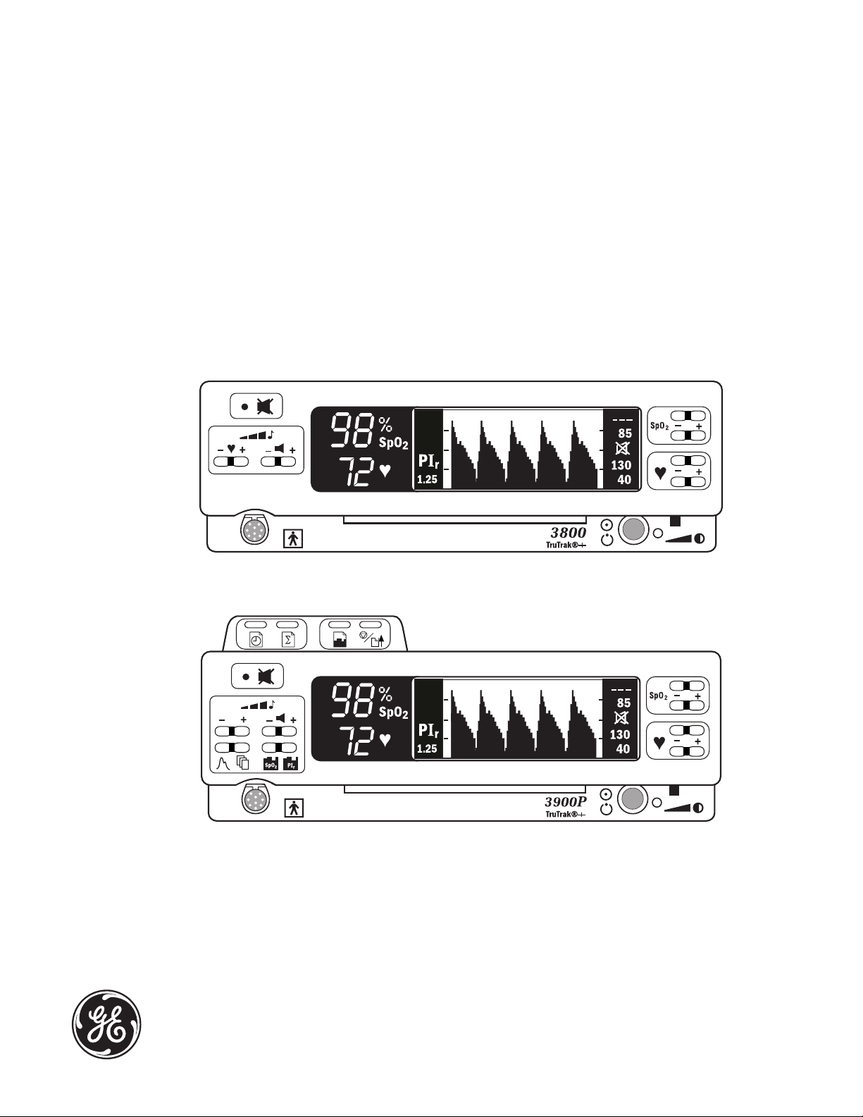
Both models feature two easy-to-read displays that present patient data and status
information.
• The numeric LEDs (light-emitting diodes) show the SpO2 and pulse rate values.
• The LCD (liquid crystal display) shows alarm messages, the plethysmographic
waveform (or data), and the high and low SpO2 and pulse rate limit settings. This
display also shows the Relative Perfusion Index (PIr®) pulsatile value and menus
as appropriate for the monitor.
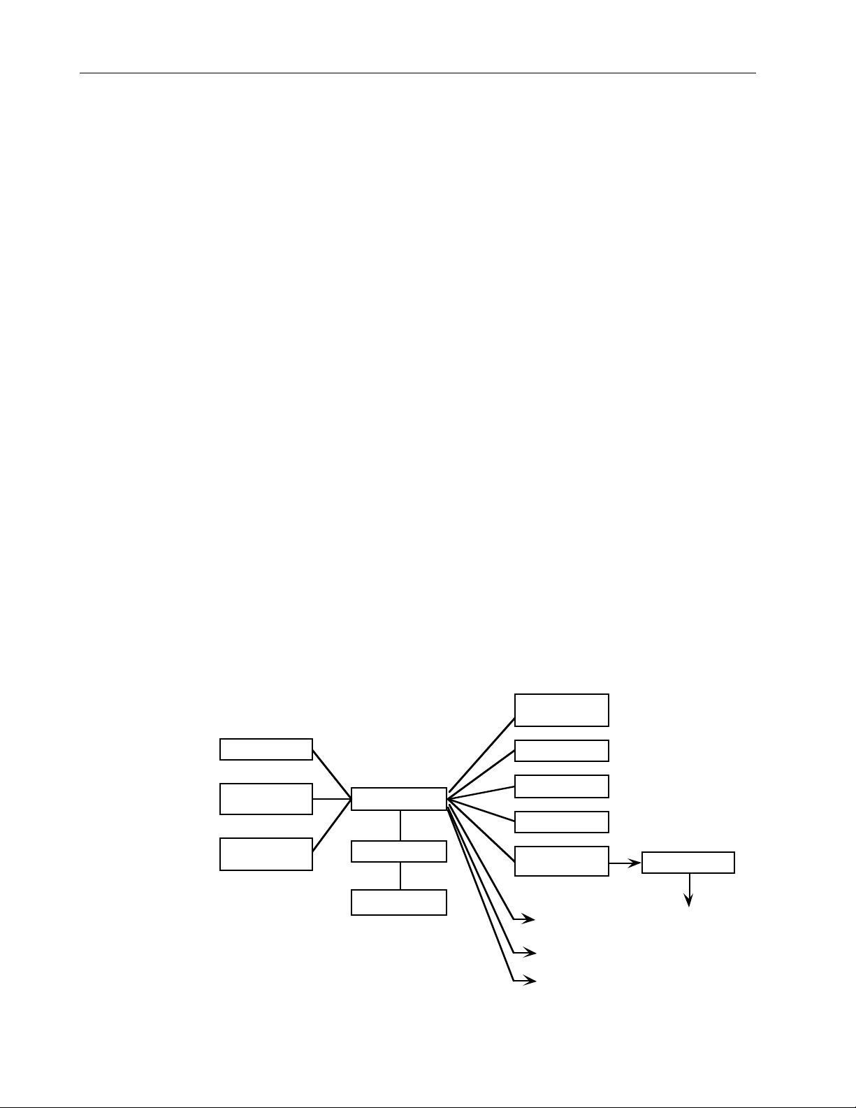
1.1.1 Major components, block interconnect diagram
AC
Power
Power inlet
module
Power supply
+12 V
Mode switches
RS-232 port
System board
Battery
1.1.2 General subassembly description
The descriptions that follow discuss the interaction of major components within the
pulse oximeter. More detailed information for each component is found in chapter 2.
Power inlet module
The primary function of the power inlet module is to allow the oximeter to be
connected to an AC power source. It also serves as a filter for electromagnetic
compatibility (EMC) compliance and contains fuses to limit the current flow. This
module is connected to the power supply.
3900P
Printer board
Oximetry board
3900P Printer
button board
Front panel
Sensor filter
board
Oximetry
sensor
1- 2

1/Overview
Power supply
The power supply converts power from any AC source between 90 and 264 VAC at
47 to 63 Hz to +12 VDC. It also provides the necessary isolation between the patient
and the mains. The +12 VDC is connected to the system board for further conditioning.
Battery
Power for the unit, when it is not connected to the AC mains power, is supplied by the
battery. The nominal battery voltage is 8 V. The battery is connected to the system
board, which conditions the battery and charges the battery when the unit is
connected to the AC mains power.
System board
This board conditions power from the +12 V power supply and the battery. It charges
the battery when supplied with a DC voltage from the power supply. On power up it
reads the position of the mode switches on the back panel. It communicates through
the RS-232 port. The board sends data to the front panel for display and monitors the
button switches. An upgrade socket on the board provides a means of upgrading the
software. The board monitors and sends commands to the oximetry board via a serial
interface and a few discrete digital lines.
The board communicates printer functions to the 3900P printer board. It also contains
a real-time clock for use in 3900/3900P monitors.
Oximetry board
This board drives the LEDs in the oximetry sensor and receives the photodetector
signals. The signals pass through the sensor filter board. The photodetector signal is
conditioned and processed on the oximetry board and the output is used to determine
patient oxygen saturation, perfusion, and pulse rate. The output is sent to the system
board.
Sensor filter board
This board filters out unwanted electrical signals (EMC, surges, noise, etc.). These are
internal signals that should not leave the unit and external signals that should not
enter the unit.
Front panel
This panel displays information sent to it by the system board: saturation, pulse rate,
plethysmographic waveform, alarm messages, and alarm indicators. The panel also
contains the primary user-interface switches. It displays the AC power status and
contains the power/standby switch.
3900P printer
The printer board and printer button board interface to the system board. The system
board controls the 3900P printer to provide printed output of current monitoring data,
stored trend, and summary data.
1- 3

3800/3900/3900P Technical Reference Manual
1.2 Compliance with standards
Compliance with standards The presence on the monitor of any symbol described
below indicates compliance with the standard represented by that symbol.
Medical Device Directive 93/42/EEC of the European Union for a class I
0537
(with a measuring function), IIa, IIb, or III device.
Medical electrical equipment classified in the US and Canada with
respect to electric shock, fire, and mechanical hazards only, in
accordance with the Canadian Standards Association CAN/CSA C22.2 No.
601.1 and Underwriters Laboratories Inc. UL 2601-1.
Medical electrical equipment classified with respect to electric shock,
fire, and mechanical hazards only, in accordance with the Canadian
Standards Association CAN/CSA C22.2 No. 601.1.
Medical electrical equipment classified with respect to electric shock,
fire, and mechanical hazards only, in accordance with Underwriters
Laboratories Inc. UL 2601-1.
1.2.1 General safety requirements
The 3800, 3900, and 3900P pulse oximeters comply with the requirements of EN 606011 Part 1: General requirements for safety of medical electrical equipment.
Type BF applied part.
Type of protection against electric shock: Class I/Internal electrical power source
Degree of protection against ingress of liquids: Ordinary (IPX0)
Mode of operation: Continuous
The oximeter also complies with the following:
EN 865 Pulse oximeters – Particular requirements
EN 475 Medical devices – Electrically-generated alarm signals.
Safety checks for software
Software design controls include performance of a risk analysis using methods
consistent with EN 1441 Medical devices – Risk analysis.
To ensure proper operation of the software, the monitor employs three separate
watchdog circuits for the microprocessors, power-on self-tests (including memory
checksum and calibration verification), and memory tests during monitoring. The
software continuously monitors the patient sensor and, if a failure is detected,
discontinues power to the sensor.
1- 4

1/Overview
1.2.2 Electromagnetic compatibility (EMC)
The 3800, 3900, and 3900P pulse oximeters comply with the requirements of EN 606011-2: Electromagnetic compatibility - Requirements and tests.
Emissions EN 55011 Group I, Class B
The 3800, 3900, and 3900P oximeters were tested with no peripheral devices when
operating on battery power.
The 3800 pulse oximeter was tested with an RS-232 cable attached when operating on
AC power.
The 3900 and 3900P pulse oximeters were tested with an RS-232 cable and analog
output cables attached when operating on AC power. A USRobotics Sportster Fax
Modem was connected to the 3900 when Electrical Safety and EMC testing was
performed. The analog output was measured using a fiber optic link during testing.
When installing and using this monitor, take precautions to ensure electromagnetic
compatibility.
Table 1-1. Guidance and manufacturer’s declaration - electromagnetic emissions
The 3800/3900/3900P TruTrak+ is suitable for use in the electromagnetic environment specified below. The customer
or the user of the 3800/3900/3900P TruTrak+ should assure that it is used in such an environment.
Emissions test Compliance Electromagnetic environment - guidance
RF emissions
Group 1
CISPR 11
RF emissions
Class B
CISPR 11
Harmonic emissions
Class A
IEC 61000-3-2
Voltage fluctuations/flicker emissions
Complies
IEC 61000-3-3
The 3800/3900/3900P TruTrak+ uses RF energy only for its
internal function. Therefore, its RF emissions are very low
and are not likely to cause any interference in nearby
electronic equipment.
The 3800/3900/3900P TruTrak+ is suitable for use in all
establishments, including domestic establishments and
those directly connected to the public low-voltage power
supply network that supplies buildings used for domestic
purposes.
1- 5

3800/3900/3900P Technical Reference Manual
Table 1-2 Guidance and manufacturer’s declaration - electromagnetic immunity
The 3800/3900/3900P TruTrak+ is intended for use in the electromagnetic environment specified below. The customer
or the user of the 3800/3900/3900P TruTrak+ should assure that it is used in such an environment:
Immunity test IEC 60601-1-2 test level Compliance level
Electrostatic
discharge (ESD)
± 6 kV contact
± 8 kV air
± 6 kV contact
± 8 kV air
IEC 61000-4-2
Electrical fast
transient/burst
± 2 kV for power supply lines
± 1 kV for input/output lines
± 2 kV for power supply lines
± 1 kV for input/output lines
IEC 61000-4-4
Surge
IEC 61000-4-5
Voltage dips,
short
interruptions
and voltage
variations on
power supply
input lines
IEC 61000-4-11
Power frequency
± 1 kV differential mode
± 2 kV common mode
< 5 % U
T
(> 95 % dip in UT) for 0,5 cycle
40 % U
T
(60 % dip in UT) for 5 cycles
70 % U
T
(30 % dip in UT) for 25 cycles
< 5 % U
T
(> 95 % dip in UT) for 5 sec
± 1 kV differential mode
± 2 kV common mode
< 5 % U
T
(> 95 % dip in UT) for 0,5 cycle
40 % U
T
(60 % dip in UT) for 5 cycles
70 % U
T
(30 % dip in UT) for 25 cycles
< 5 % U
T
(> 95 % dip in UT) for 5 sec
3 A/m 3 A/m Power frequency magnetic fields
(50/60 Hz)
magnetic field
IEC 61000-4-8
NOTE: UT is the a.c. mains voltage prior to application of the test level.
Electromagnetic environment -
guidance
Floors should be wood,
concrete, or ceramic tile. If
floors are covered with
synthetic material, the relative
humidity should be at least
30%.
Mains power quality should be
that of a typical commercial or
hospital envi ronment
Mains power quality should be
that of a typical commercial or
hospital envi ronment.
Mains power quality should be
that of a typical commercial or
hospital environment. If the
user of the 3800/3900/3900P
TruTrak+ requires continued
operation during power mains
interruptions, it is
recommended that the
3800/3900/3900P TruTrak+ be
powered from an
uninterruptible power supply
or a battery.
should be at levels
characteristic of a typi cal
location in a typical commercial
or hospital environment.
1- 6
1/Overview
Table 1-3 Guidance and manufacturer’s declaration - electromagnetic Immunity
The 3800/3900/3900P TruTrak+ is intended for use in the electromagnetic environment specified below. The customer
or the user of the 3800/3900/3900P TruTrak+ should assure that it is used in such an environment:
Immunity test IEC 60601 test level Compliance level Electromagnetic environment - guidance
Portable and mobile RF communications equipment
should be used no closer to any part of the
3800/3900/3900P TruTrak+, including cables, than the
recommended separation distance calculated from
the equation applicable for the frequency of the
transmitter.
Recommended Separation Distance
Conducted RF
IEC 61000-4-6
Radiated RF
IEC 61000-4-3
3 Vrms
150 kHz to 80 MHz
3 V/m
80 MHz to 2,5 GHz
5 V
5 V/m
where P is the maximum output power rating of the
transmitter in watts (W) according to the transmitter
manufacturer and d is the recommended separation
dis tance in meters (m).
Field strengths from fixed RF transmitters, as determined by an electromagnetic site survey,
be less than the compliance level in each fre quency
range.
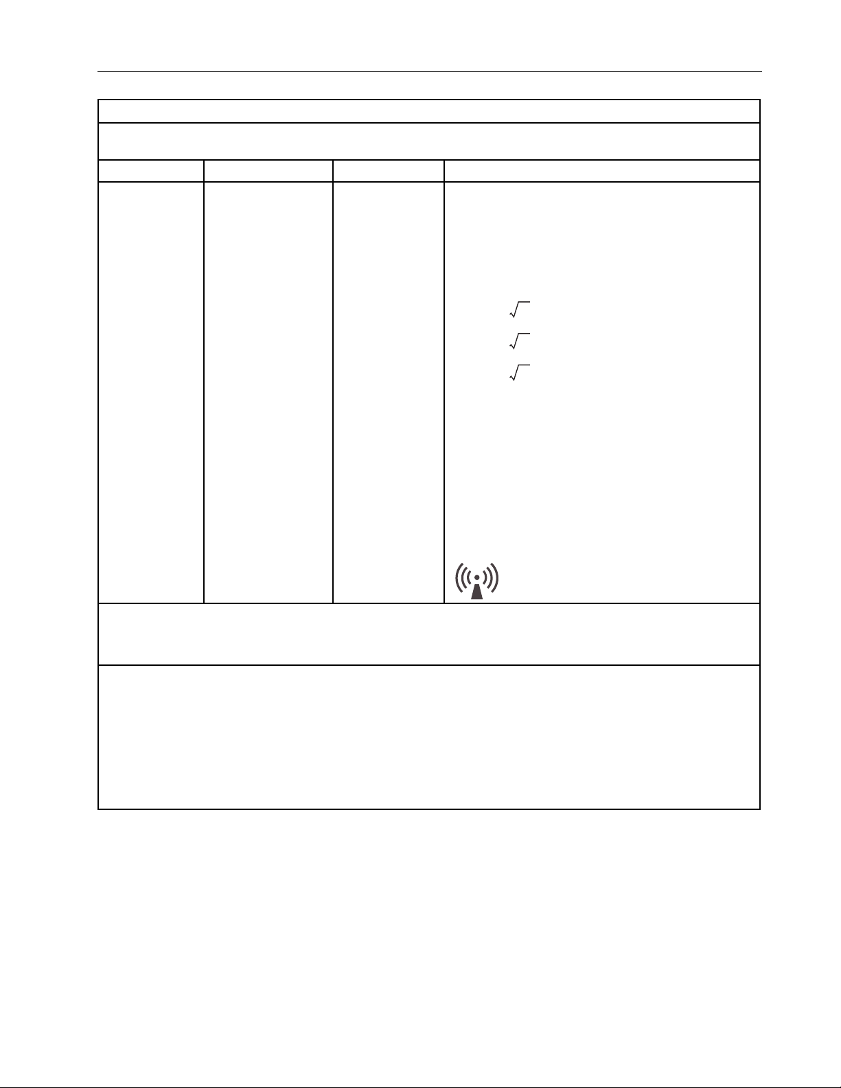
Interference may occur in the vicinity of equipment
marked with the following symbol:
Pd = 0.70
Pd = 0.70
80 MHz to 800 MHz
Pd = 1.40
800 MHz to 2,5 GHz
a
should
b
NOTE 1: At 80 MHz and 800 MHz, the separation distance for the higher frequency range applies.
NOTE 2: These guidelines may not apply in all situations. Ele ctromagnetic propagation is affected by absorption
and reflection from structures, objects, and people.
a
Field strengths from fixed transmitters, such as base stations for radio (cellular/cordless) telephones and land
mobile radios, amateur radio, AM and FM radio broadcast, and TV broadcast cannot be predicted theoretically
with accuracy. To assess the electromagnetic environment due to fixed RF trans mitters, an electromagnetic site
survey should be considered. If the measured field strength in the location in which the 3800/3900/3900P TruTrak+
is used exceeds the applicable RF compliance level above, the 3800/3900/3900P TruTrak+ should be observed to
verify normal operation. If abnormal performance is observed, additional measures may be necessary, such as reorienting or relocating the 3800/3900/3900P TruTrak+.
b
Over the frequency range 150 kHz to 80 MHz, field strengths should be less than 5 V/m.
1- 7

3800/3900/3900P Technical Reference Manual
Electromagnetic effects
Electromagnetic interference, including interference from portable and mobile radio
frequency (RF) communications equipment, can affect this monitor.
Table 1-4 Recommended Separation Distances between Portable and Mobile RF Communications
Equipment and the 3800/3900/3900P TruTrak+
The 3800/3900/3900P TruTrak+ is intended for use in an electromagnetic environment in which RF disturbances are
controlled. The customer or the user of the 3800/3900/3900P TruTrak+ can prevent electromagnetic interference by
maintaining a minimum distance between portable and mobile RF communications equipment (transmitters) and
the 3800/3900/3900P TruTrak+ as recommended below, according to the maximum output power of the
communications equipment.
Rated maximum output
power of transmitter
W
0.01 0.07 0.07 0.14
0.1 0.22 0.22 0.44
1 0.70 0.70 1.40
10 2.2 2.2 4.4
100 7.0 7.0 14.0
For transmitters rated at a maximum output power not listed above, the recommended separation distance d in
meters (m) can be estimated using the equation applicable to the frequency of the transmitter, where P is the
maximum output power rating of the transmitter in watts (W) according to the transmitter manufacturer.
NOTE 1: At 80 MHz and 800 MHz, the separation distance for the higher frequency range applies.
NOTE 2: These guidelines may not apply in all situations. Electromagnetic propagation is affected by absorption
and reflection from structures, objects, and people.
Separation distance according to the frequency of the transmitter
m
150 kHz to 80 MHz
Pd = 0.70
80 MHz to 800 MHz
Pd = 0.70
800 MHz to 2,5 GHz
Pd = 1.40
1- 8
Indications that the monitor is experiencing electromagnetic interference include the
following:
• Variations in the PerfTrak waveform display.
• Sudden increases or decreases in the waveform height that do not correlate to the
physiological condition of the patient.
• Sensor-related messages that are not resolved by the instructions found in this
manual.
• The display of dashes on numeric LEDs when a valid physiological signal is
present.
• (3900P ) Printed output that is garbled, solid black, or missing.
This interference may be intermittent and careful correlation between the effect and its
possible source is important. Indications of interference should not occur if the
monitor is used within its intended electromagnetic environment.

1.3 Specifications
Unless otherwise indicated, all specifications are nominal and are subject to change
without notice.
1.3.1 General
Circuitry
Microprocessor-controlled
Automatic self-test of oximeter when powered on
Automatic setting of default parameters
Automatic alarm messages
(3800) Up to 12 hours of stored trend data output through the RS-232 serial port for SpO2,
pulse rate, and alarm messages
(3900/3900P) Real-time data output or up to 24 hours of stored trend data output
through the RS-232 port for SpO2, pulse rate, PIr pulsatile value, and alarm messages;
SpO2 and pulse rate output through two analog channels
Displays
The displayed SpO2, pulse rate, and PIr values are updated every second. The
plethysmographic waveform sweep is updated every 4 seconds.
1/Overview
Numeric display (Light Emitting Diodes—LEDs)
Arterial oxygen saturation (SpO2) reading
Pulse rate reading
Graphic display (Liquid Crystal Display—LCD)
Plethysmographic waveform
High and low SpO2 and pulse rate alarm limits settings
Sensor condition alarms
Messages—alarm messages and system operational status messages
Contrast adjustment
(All monitors except 3800 without TruTrak+) PIr pulsatile value
(3900/3900P) SpO2 real-time or stored data graph
(3900/3900P) PIr pulsatile value real-time or stored data graph
Audio indicators
Adjustable-volume pulse beep; pitch modulation reflects changing SpO2 levels
Adjustable-volume alarm tone
Alarm silence (120 seconds); all mute (continuous silence)
Out-of-limits alarms for SpO2 and pulse rate
Sensor-condition, system-failure, and recharge-battery alarms
Dimensions and weight
(3800/3900) height x width x depth: 9.4 cm (3.7 in) x 24.4 cm (9.5 in) x 22.5 cm (8.9 in)
(3900P) height x width x depth: 10.4 cm (4.1 in) x 24.4 cm (9.5 in) x 22.5 cm (8.9 in)
Weight: 3800/3900—2.9 kg (6.5 lbs); 3900P —3.2 kg (7.0 lbs)
1- 9

3800/3900/3900P Technical Reference Manual
1.3.2 Factory settings
Parameter 3900/3900P 3800
High SpO2 limit OFF (appears as – – –) OFF (appears as – – –)
Low SpO2 limit 85% 85%
High pulse rate 130 bpm Adult mode: 130 bpm
Low pulse rate 40 bpm Adult mode: 40 bpm
Alarm volume 3 3
Pulse volume 2 2
Save limits No Not applicable
Data output mode
(printer and modem)
Data output resolution 6-second Not applicable
All mute Yes Not applicable
Serial transmission
baud rate
Analog 0.0 V Not applicable
Print contrast 5 Not applicable
Date format DD/MM/YY Not applicable
Time format HH MM Not applicable
Neonate mode: 200 bpm
Neonate mode: 100 bpm
SpO
2
9600 Not applicable
Not applicable
Mode switches
Switch 3900/3900P options 3800 options
Language Danish, Dutch, English
(factory setting), Finnish,
French, German, Italian,
Japanese, Norwegian,
Portuguese, Polish,
Spanish, and Swedish
Averaging mode Long / TruTrak+ (12 sec.
factory setting), Medium
(6 sec.), and Short (3 sec.)
Patient mode Not applicable Adult (factory setting) and
(TruTrak+ monitors) PI
pulsatile value display
(Monitors without TruTrak+)
SpO2 calibration
EMI line frequency 60 Hz 60 Hz
Yes (factory setting) and No Yes (factory setting) and No
r
Fractional (factory setting)
and functional
English (factory setting),
French, German, Italian,
Japanese, Portuguese,
Spanish, and Swedish
Long / TruTrak+ (12 sec.
factory setting), Medium
(6 sec.), and Short (3 sec.)
Neonate
Fractional (factory setting)
and functional
1- 1 0

1.3.3 Measurement
1/Overview
SpO
2
Calibration Functional Fractional or Functional
Range 0 to 100% 0 to 100%
Accuracy, A
(previously
represented
by 1 SD)
Accuracy, 1 SD 80 to 100% ± 2%
Resolution 1% 1%
rms
Pulse rate
Range 30 to 250 bpm 20 to 255 bpm
Accuracy
(assuming a
constant
pulse rate)
Resolution 1 bpm 1 bpm
TruTrak+ monitors Monitors without TruTrak
70 to 100% ± 2 digits
70 to 100% ± 3 digits during
conditions of clinical patient
motion (with TruTrak+ enabled)
Below 70% unspecified
60 to 79% ± 3%
Below 60% unspecified
TruTrak+ monitors Monitors without TruTrak
± 2% or ± 2 bpm (whichever is
greater)
Accuracy during conditions of
clinical patient motion:
unspecified
40 to 235 bpm ± 1.7% of
reading
+
+
PIr pulsatile value
Range 0.00 to 9.99 Not applicable
Averaging
interval
Resolution 0.01 Not applicable
TruTrak+ monitors
and 3900/3900P without
TruTrak
12 seconds Not applicable
+
3800 without TruTrak
Interfering substances
Carboxyhemoglobin may erroneously increase readings. The level of increase is
approximately equal to the amount of carboxyhemoglobin present. Dyes, or any
substances containing dyes, that change usual arterial pigmentation may cause
erroneous readings.
Sensor emitter wavelength ranges
Red LED peak wavelength range: 650 to 670 nm
Infrared (IR) LED peak wavelength range: 930 to 950 nm
Average power: ≤ 1 mW
+
1- 1 1

3800/3900/3900P Technical Reference Manual
1.3.4 Alarms
Audible alarms
Setting levels available:
Alarm: 1 through 5
Pulse beep: OFF and 1 through 5
Volume intensity at 1-meter distance:
Setting of 1: 45 decibels (minimum)
Setting of 5: 85 decibels (maximum)
Alarm limits
SpO2 alarm limit range:
High = 50 to 100%, or OFF
Low = OFF, or 50 to 100%
Pulse rate alarm limit range in beats per minute (bpm):
TruTrak+ monitors Monitors without TruTrak
High = 30 to 235, or OFF
Low = OFF, or 30 to 235
+
High = 40 to 235, or OFF
Low = OFF, or 40 to 235
1.3.5 Environmental
Parameter Operating Transport and Storage
Temperature 0 to 50 ºC (32 to 122 ºF) –40 to 70 ºC (–40 to 158 ºF)
Relative humidity,
noncondensing
Pressure 1060 to 697 hPa 1060 to 188 hPa
Approximate
elevation
1.3.6 Electrical
Power
Consumption (typical): 15 watts (3900P—20 watts)
Input voltage range: 90 to 264 VAC at 47-63 Hz
Current (typical): 0.45 A
Current leakage
With power on, forward or reverse polarity: 100 microamperes maximum
Ground resistance: less than 0.1 Ω
3900P with printer paper:
–20 to 45 °C (4 to 113 °F)
20% to 95% 5% to 95%
–378 to 3048 m
(–1240 to 10,000 ft.)
at 100 V, 0.37 A
rms
at 120 V, 0.25 A
rms
–378 to 12.2 km
(–1240 to 40,000 ft.)
at 220/230/240 V
rms
1- 1 2
Fuse
T2.0AH/250V, 5mm (OD) x 20 mm (Length)

Battery
Type: 8 volt, sealed lead-acid
Capacity: 3.2 ampere hours
Operation time for a new battery at normal operating temperatures:
At least 5 1/2 hours (with all functions operative from a fully charged battery).
3900P —approximately 4 hours when printing.
Low battery indicator (LOW BATTERY): indicates the remaining battery capacity is
between 5 and 15 minutes.
Important: To prevent permanent damage to the battery, recharge a discharged
battery within eight hours after LOW BATTERY is displayed.
Charge time:
4 hours = 80% capacity
8 hours = 100% capacity
Life: several hundred charge/discharge cycles
Shelf life: 6 months (maximum if not recharged) when stored at room temperature;
batteries stored for extended periods of time should be recharged every six months
to maintain the charging capacity.
1/Overview
1.3.7 RS-232 connector
Connector type: 9-pin standard D, female
3900/3900P—pins 1 and 4 are not used.
3800—pins 1, 4, 6 and 9 are not used.
Serial output
RS 232
1
Data output every 2 seconds (auto-output mode) or 6 seconds (trend-output mode):
• (All monitors) SpO2, pulse rate, alarm limit violation messages, and displayed
alarm messages
• (3900/3900P) Relative Perfusion Index, time stamp, and custom patient label
Baud rate: 3800—9600 baud; 3900/3900P—9600, 19.2 K, 38.4 K, or 57.6 K baud
Full duplex; no parity
8 bits per character; 1 start bit; 1 stop bit
Handshaking: CTS/RTS
(3900/3900P) Analog output
2 = oximeter receives data
3 = oximeter transmits data
5 = signal ground
7 = RTS (Request To Send)
8 = CTS (Clear To Send)
RS 232
5 = signal ground
1
6 = SpO2 (0 to 1 Vdc ± 20 mV = 0 to 100% ± 2.0%)
9 = Pulse rate (0 to 1 Vdc ± 20 mV = 0 to 255 bpm ± 2.0%)
1- 1 3

3800/3900/3900P Technical Reference Manual
1.4 Precautions
Two types of precautions appear in this manual: Warnings and cautions.
• A WARNING indicates the possibility of injury to the patient or operator.
• A CAUTION indicates a condition that may cause equipment damage or
malfunction.
(3900/3900P) If you connect a modem, refer to the precautions contained in the
instructions that accompanied your modem.
1.4.1 Warnings
Battery replacement
To ensure proper operation, replace only with the recommended battery.
Failure of operation
If the oximeter fails any part of the checkout procedures or current leakage test,
remove it from operation until qualified service personnel have corrected the situation.
Data validity
Conditions that may cause inaccurate readings and impact alarms include interfering
substances, excessive ambient light, electrical interference, excessive motion, low
perfusion, low signal strength, incorrect sensor placement, poor sensor fit, and
movement of the sensor on the patient.
To prevent erroneous readings, do not use an inflated blood pressure cuff or arterial
blood pressure measurement device on the same limb as the oximeter sensor.
Electrical shock hazard
Measure the oximeter’s leakage current in accordance with applicable standards after
completing any repair procedure.
This equipment must be properly grounded.
• Electrical safety specifications (e.g., current leakage and ground resistance) can be
assured only when the oximeter is connected to a three-wire, grounded, receptacle
without the use of extension cords or adapters.
• If there is any doubt about the integrity of the AC power supply protective earth
conductor, operate the oximeter on internal battery power.
• Because the unit is not grounded when it is operating on battery power, do not
connect any equipment to the RS-232 port on the rear panel unless the unit is
connected to the AC power supply.
Before cleaning or repairing the monitor, turn it off and disconnect it from AC mains
power.
Fire/explosion hazard
Replace fuses only with fuses of the same type and voltage rating.
Do not use the monitor in the presence of any flammable anesthetic mixture.
1- 1 4

Patient safety
Never test or perform maintenance on the oximeter while it is being used to monitor a
patient.
Sensors
To prevent injury or equipment damage, use only oximeter sensors approved for use
with this oximeter. For complete information about the safe and appropriate use of a
sensor, consult the instructions for that sensor.
Discard a damaged sensor immediately. Do not repair a damaged sensor or use a
sensor repaired by others.
1.4.2 Cautions
General
US Federal law restricts this device to sale by or on the order of a licensed medical
practitioner.
Only qualified service personnel should perform the procedures described in this
manual.
Handle the monitor with care. Improper handling can cause damage or inaccurate
results.
1/Overview
Static sensitivity
Internal electronic components are susceptible to damage by electrostatic discharge.
To avoid damage when disassembling the oximeter, observe the standard precautions
and procedures for handling static-sensitive components.
(3900P ) To avoid damage to the print head from electrostatic discharge, take special
care when servicing the 3900P printer.
Sensors
Do not apply tension to the sensor cable; sensor damage may result.
Cleaning
Do not autoclave, pressure sterilize, or gas sterilize this oximeter.
Use cleaning solution sparingly. Do not soak or immerse the oximeter in liquid.
Excessive solution can flow into the oximeter and damage internal components.
When cleaning the display area, do not use abrasive cleaning compounds or other
materials that could damage the screen.
Do not use petroleum-based solutions, acetone solutions, or other harsh solvents to
clean the oximeter. These substances may damage the oximeter and cause a
malfunction.
(3900P ) Do not allow cleaning solution to get into the printer mechanism.
Disposal
Dispose of this medical device and its packaging according to local requirements.
Dispose of the battery, which contains lead and acid, through an approved hazardous
materials disposal facility.
1- 1 5

3800/3900/3900P Technical Reference Manual
1.5 Safety guidelines
Before you start any procedure that involves disassembly of the oximeter, review these
guidelines to ensure the proper and safe completion of the procedure.
WARNING: Patient safety. Never test or perform maintenance on the oximeter while it
is being used to monitor a patient.
WARNING: Electrical shock hazard. Before cleaning or repairing the monitor, turn it off
and disconnect it from AC mains power.
1. Power off and disconnect the unit from the AC power supply.
2. Disconnect the sensor from the unit.
3. Clean the unit—see section 1.5.1.
4. Read and follow each step of all test and repair procedures. Give special attention
to all warnings and cautions.
Important: After repairs are complete, test the unit as directed at the end of each
procedure to verify that it is functioning properly.
1.5.1 Cleaning
You must clean the oximeter,
• Before you start any procedure that involves disassembly of the oximeter.
• Before you send the oximeter for repair.
CAUTION: Cleaning
• Do not autoclave, pressure sterilize, or gas sterilize the oximeter.
• Use cleaning solution sparingly. Do not soak or immerse the monitor in liquid.
• When cleaning the display area, do not use abrasive cleaning compounds or other
• Do not use petroleum-based solutions, acetone solutions, or other harsh solvents
• To prevent damage to the 3900P printer, do not allow cleaning solution to get into
1. Turn off the oximeter and disconnect it from AC mains power.
2. Gently wipe the display panel with a cotton swab moistened with isopropyl
3. To clean the out er surface of the oximeter, use a soft cloth dampened with a mild
Excessive solution can flow into the monitor and damage internal components.
materials that could damage the screen.
to clean the oximeter. These substances may damage the oximeter and cause a
malfunction.
the printer mechanism.
alcohol (70 vol%).
soap and water solution or one of the following solutions:
1- 1 6
Mild detergent solution 0.5% sodium hypochlorite (bleach)
70% isopropyl alcohol Quarternary germicides (Virex®)
1.6% phenol (Sporicidin®) 3.4% glutaraldehyde (Cidex® Plus)

2/Theory of Operations
This chapter covers the theory of operations for the following components:
• Power supply and power inlet module
• System board
• Switch board
• Oximetry board
• Passive filtering
• 3900P printer interface
2.1 Power supply and power inlet module
The power supply converts power from an AC power source to +12 VDC. It also provides
the necessary isolation between the patient and the AC power supply. It is connected
to the system board for further conditioning.
The power inlet module contains the three-contact power connector and the fuses.
Block diagram
To AC power supply
Power inlet
module
Off-line switching
power supply
12 VDC
To system board
2- 1
3800/3900/3900P Technical Reference Manual
2.2 System board
The system board has two major components:
• Data management section
• Power management section
System board functions
• Condition power from the AC power supply and the battery.
• Charge the battery when supplied with a DC voltage from the power supply.
• Monitor language mode switch positions.
• Provide bi-directional communication through the RS-232 connector.
• Send data to the front panel for display.
• Monitor front panel button presses.
• Allow for software upgrades.
• Monitor and send commands to the oximetry board via a serial interface and a few
discrete digital lines.
• (3900/3900P) Send analog SpO2 and pulse rate data to analog outputs.
• (3900/3900P) Provide real-time clock capability.
• (3900P) Provide control for printer output.
2.2.1 System board data management
The digital section of the system board provides data management. The digital section
contains the microprocessor, SRAM, Flash memory, a software upgrade socket, the
RS-232 interface, mode switches, alarm signal generator, audio amplifier,
microprocessor supervision, 3900/3900P real-time clock capability, and 3900P printer
interface.
Block diagram
Mode switches
Microprocessor
supervisor
Background
debug
Microprocessor
Isolation
RS-232 connector
(3900/3900P)
Real-time clock
Static memory
Flash memory
Upgrade socket
Alarm tone
generator
To oximetry board
To front panel
Audio driver
Speaker
2- 2
(3900P) To printer board

2/Theory of Operations
Microprocessor
The microprocessor is a Motorola 68332 that operates at 16 MHz. It uses a crystal that
operates at 32.768 KHz. Several ports can be configured by software. A 16-channel timer
processing unit can be programmed to execute various timing functions, including a
serial communication port. A background debug feature allows full access to the
processor through a 10-pin connector. Communication to the oximetry board is
accomplished primarily through a dedicated serial port.
SRAM
The static RAM is 128 K x 8 bits. The SRAM is powered when the unit is in standby mode,
which allows data to be retained when the digital system is powered down.
Flash memory and software upgrade socket
The Flash memory (512 K x 8 bits) contains the application code software, which runs
the oximeter. An upgrade socket allows download of revisions to the application code
software. The software upgrade socket accepts a memory chip with the same pinout as
the onboard Flash memory. A super cap provides flash memory backup while the
battery is disconnected.
RS-232 connector interface
This port, which operates at 9600 baud (3800) or 9600, 19.2K, 38.4K, or 57.6K baud
(3900/3900P), allows for transmission of oximetry data to other serial devices. It has
optoisolators and an isolated power supply so that there is no ohmic connection
between the connector and the digital system.
(3900/3900P) Two analog outputs allow SpO2 and pulse rate outputs in analog form, at
0 to 1 volt full scale.
Mode switch
The mode switch settings determine the modes of operation for the oximeter, such as
the averaging mode, for example. The switches are ESD-protected by a 14-channel dual
SCR chip connected to the power supply. The positions of the switches are read directly
through 8 of the TPU channels.
Alarm signal and pulse tone generator
This is a sawtooth generator. The circuit produces a signal that is rich in harmonics. A
resistor in the feedback loop controls the slope of the rising edge while another resistor
controls the slope of the falling edge. The frequency is set to about 800 Hz. Volume is
controlled by the microprocessor using pulse width modulation (PWM). Another PWM
channel on the microprocessor generates pulse tones; the microprocessor controls the
frequency of this tone. Discrete logic is incorporated to produce an alarm tone at full
volume in the event that the microprocessor is not operating.
Microprocessor supervisor
This chip monitors the power supply, contains a watchdog, has battery switchover
circuitry, generates reset pulses, and disables the SRAM during power down. If the
power supply voltage is too low, this circuit holds the reset on the processor until the
correct voltage is restored. It also switches the SRAM supply power to the Vbatt input
and disables RAM when the supply voltage is low. If the microprocessor does not pulse
the watchdog input occasionally, the chip issues a reset pulse. It also enables the
alarm tones if the watchdog is active.
2- 3

3800/3900/3900P Technical Reference Manual
Audio amplifier
This is a single chip that amplifies the audio tones. It has a bipolar output that allows
for maximum volume with a single supply. The amplifier has a low-pass pole at 17.5
KHz to reduce noise which may be picked up at the input to the amplifier.
Front panel interface
Switches on the front panel are read via various discrete I/O lines on the processor.
They are scanned via an output port on the front panel circuit board (the switch board).
The numeric displays on the front panel are sent data via the serial peripheral interface
of the processor.
Background debug
A 10-pin connector allows direct connection to the microprocessor. All microprocessor
functions can be accessed through this interface.
Boot code and application code can be downloaded via this connector.
(3900/3900P) Real-time clock
This is a single chip connected to the microprocessor. It provides time, month, day, and
year for the display and for printed trend data. A super cap provides backup while the
battery is disconnected.
(3900P) Printer interface
A connector and port allow the microprocessor to control printer functions.
Handshaking lines synchronize the printer to the microprocessor. The microprocessor
directly controls the printhead patterns for text and graphic images.
2.2.2 System board power management
The power management section generates + 5 V, switches between the + 12 V and
battery supplies, charges and monitors the battery voltage, and controls power on and
standby modes.
Block diagram
AC monitor
+ 12 V
input
Battery charger
Battery
input
Battery voltage
monitor
+ 5 V supply
+ 5 V is generated by a buck-switching regulator that operates at 52 KHz. The input
voltage is between about + 6.7 and + 12 V. This supplies power to the digital section, the
front panel, and the oximetry board.
Switchover circuit
Front panel switch
+ VR regulator
+ 5 V switching
regulator
Power on /
standby control
Microprocessor
supervisor
Memory
2- 4

2/Theory of Operations
Battery charger
The battery charger is designed specifically for lead-acid batteries. If the battery
voltage is less than 6.52 V, the circuit charges the battery at a low current. After the
battery reaches voltage 6.52 V, it charges the battery at 625 mA. When the battery
reaches 9.8 V, the charger changes to a constant voltage charger. When the charging
current is less than 31 mA, the charger goes into a float state holding the battery
voltage at 9.4 V.
Battery monitor
The battery is monitored for low voltage and recharge. The low voltage trip point is set
at 7.3 V, and the recharge-battery-voltage trip point is set at 7.0 V. The low battery
signal is sent to the microprocessor. The recharge battery signal is latched with
discrete logic. In the event that a recharge battery condition is reached, the unit must
be connected to AC mains power to reset the recharge battery latch.
AC monitor
+ 12 V is used to indicate that the unit is connected to AC mains power. This signal is
level shifted to + 5 V and sent to the processor.
+ VR supply
+ VR is generated by a low power linear regulator set as about 4 V. This voltage is
routed to the microprocessor supervisor Vbatt input. It supplies power to the power
on/standby circuitry, SRAM, and the recharge battery latch when the unit is in standby
mode. It also supplies power to the real-time clock. This supply is backed up by a super
cap during periods when the battery is disconnected.
Power on/standby circuitry
The input to the + 5 V switching regulator is controlled by a P channel FET. The gate of
the FET is controlled by a transistor whose base is connected to a flip-flop. The state of
this flip-flop determines the on or standby state of the unit. The circuit senses when the
front panel power switch is depressed. When this switch is closed, a flip-flop is toggled.
If the unit was in standby, the unit changes to the on state. If the unit is on, the circuit
generates a power-down request. This signal then goes to the microprocessor.
After the microprocessor finishes any tasks deemed necessary, the microprocessor
issues a power-down command. This signal then clears both flip-flops and puts the unit
in the standby mode. In the event that the microprocessor does not respond with a
power-down command within about 800 ms, the circuit times out and clears the flipflops.
2- 5

3800/3900/3900P Technical Reference Manual
2.3 Switch board
The switch board provides the interface between the system board and the liquid
crystal display (LCD), the drive electronics for the light emitting diode (LED) numeric
displays, and the user interface switches. It also interfaces the bicolor alarm LED, the
power/standby switch, and the LCD contrast adjustment potentiometer.
Block diagram
To system
board
Alarm indicator Saturation display Graphic display
User buttonsPulse rate displayAC power indicator
The LCD is controlled by the system board over the data bus. A hardware line, RESET,
blanks the display. The user controls the contrast (or viewing angle) of the LCD by the
position of potentiometer R6.
The LED numeric displays are driven by an LED interface chip that is controlled by the
system board over a synchronous serial interface. The maximum intensity of the
displays is set by a resistor. One end of the resistor is controlled by a latch to allow the
LEDs to be blanked when the latch is reset.
The alarm LED is bicolor (red and yellow) and is controlled by two bits of a latch.
The mains power indicator is a green LED that is lit when the oximeter is plugged into
AC mains power.
The user interface switches are configured in a matrix and are scanned by the system
board.
The power/standby switch is a momentary contact switch that is wired through to the
system board.
Contrast adjust
2- 6
 Loading...