

Page 1
Audio
Embedder
3GSDI
Release A2
User Manual
EXT-HD-VWC-144
HD
Video Wall
Controller
Page 2

HD Video Wall Controller
Important Safety Instructions
ii
GENERAL SAFETY INFORMATION
1. Read these instructions.
2. Keep these instructions.
3. Heed all warnings.
4. Follow all instructions.
5. Do not use this product near water.
6. Clean only with a dry cloth.
7. Do not block any ventilation openings. Install in accordance with the manufacturer’s
instructions.
8. Do not install or place this product near any heat sources such as radiators, heat
registers, stoves, or other apparatus (including ampliers) that produce heat.
9. Do not defeat the safety purpose of the polarized or grounding-type plug. A polarized
plug has two blades with one wider than the other. A grounding type plug has two
blades and a third grounding prong. The wide blade or the third prong are provided for
your safety. If the provided plug does not t into your outlet, consult an electrician for
replacement of the obsolete outlet.
10. Protect the power cord from being walked on or pinched particularly at plugs,
convenience receptacles, and the point where they exit from the apparatus.
11. Only use attachments/accessories specied by the manufacturer.
12. To reduce the risk of electric shock and/or damage to this product, never handle or
touch this unit or power cord if your hands are wet or damp. Do not expose this
product to rain or moisture.
13. Unplug this apparatus during lightning storms or when unused for long periods of time.
14. Refer all servicing to qualied service personnel. Servicing is required when the
apparatus has been damaged in any way, such as power-supply cord or plug is
damaged, liquid has been spilled or objects have fallen into the apparatus,
the apparatus has been exposed to rain or moisture, does not operate normally,
or has been dropped.
15. Batteries that may be included with this product and/or accessories should never be
exposed to open ame or excessive heat. Always dispose of used batteries
according to the instructions.
Page 3

HD Video Wall Controller
Warranty Information
Gefen warrants the equipment it manufactures to be free from defects in material and
workmanship.
If equipment fails because of such defects and Gefen is notied within two (2) years from
the date of shipment, Gefen will, at its option, repair or replace the equipment, provided
that the equipment has not been subjected to mechanical, electrical, or other abuse or
modications. Equipment that fails under conditions other than those covered will be
repaired at the current price of parts and labor in effect at the time of repair. Such repairs
are warranted for ninety (90) days from the day of reshipment to the Buyer.
This warranty is in lieu of all other warranties expressed or implied, including without
limitation, any implied warranty or merchantability or tness for any particular purpose, all of
which are expressly disclaimed.
1. Proof of sale may be required in order to claim warranty.
2. Customers outside the US are responsible for shipping charges to and from Gefen.
3. Copper cables are limited to a 30 day warranty and cables must be in their original
condition.
The information in this manual has been carefully checked and is believed to be accurate.
However, Gefen assumes no responsibility for any inaccuracies that may be contained
in this manual. In no event will Gefen be liable for direct, indirect, special, incidental, or
consequential damages resulting from any defect or omission in this manual, even if
advised of the possibility of such damages. The technical information contained herein
regarding the features and specications is subject to change without notice.
For the latest warranty coverage information, refer to the Warranty and Return Policy under
the Support section of the Gefen Web site at www.gefen.com.
PRODUCT REGISTRATION
Please register your product online by visiting the Register Product page under the
Support section of the Gefen Web site.
iii
Page 4

iv
HD Video Wall Controller
Gefen, LLC
c/o Customer Service
20600 Nordhoff St.
Chatsworth, CA 91311
Telephone: (818) 772-9100
(800) 545-6900
Fax: (818) 772-9120
Email: support@gefen.com
Visit us on the Web: www.gefen.com
Technical Support Hours: 8:00 AM to 5:00 PM Monday - Friday, Pacic Time
HD Video Wall Controller is a trademark of Gefen, LLC.
Important Notice
Gefen, LLC reserves the right to make changes in the hardware, packaging, and any
accompanying documentation without prior written notice.
© 2013 Gefen, LLC. All Rights Reserved.
All trademarks are the property of their respective owners.
Contacting Gefen Technical Support
Page 5

v
HD Video Wall Controller
• The HD Video Wall Controller only operates in 2x2 (two rows of two displays) mode,
only. This unit does not support 4x1 (column) or 1x4 (row) congurations.
Operating Notes
Page 6

vi
Features and Packing List
Features
• Create a 2x2 video wall from any Hi-Def source, using four HDTV displays
• Split and scale a single Hi-Def source to four displays
• Input and Output resolutions up to 1080p Full HD and 1920x1200 (WUXGA)
• HDCP compliant
• Advanced Bezel Compensation feature provides compatibility with virtually any screen
frame width, and allows for accurate display of the image
• Controllable via front panel, IR, IP (web server interface, Telnet, and UDP), and
RS-232
• Easy to use on-screen Graphical User Interface (GUI)
• Advanced web server interface using an external computer
• Handheld IR remote control
• Field-upgradeable rmware via web server interface
• USB port (reserved for future product enhancements)
• Locking power supply connector
• 1U tall rack-mountable enclosure, rack ears included
Packing List
The HD Video Wall Controller ships with the items listed below. If any of these items are not
present in the box when you rst open it, immediately contact your dealer or Gefen.
• 1 x HD Video Wall Controller
• 1 x 6 ft. Locking HDMI Cable (M-M)
• 1 x 6 ft. DB-9 Cable (M-F)
• 1 x IR Extender Module
• 1 x IR Remote Control
• 1 x 12V DC Locking Power Supply
• 1 x Set of Rack Ears
• 1 x Quick-Start Guide
HD Video Wall Controller
1080P
®
Page 7

Page 8

3GSDI Audio Embedder
HD Video Wall Controller
Table of Contents
viii
01 Getting Started
Panel Layout ......................................................................................................... 2
Front .............................................................................................................. 2
Back .............................................................................................................. 3
IR Remote Control Unit ......................................................................................... 4
Top ................................................................................................................ 4
Bottom ........................................................................................................... 6
Installing the Batteries ................................................................................... 7
Setting the IR Channel .................................................................................. 8
Installation ............................................................................................................. 9
Connecting the HD Video Wall Controller ..................................................... 9
Sample Wiring Diagram ................................................................................ 9
02 Operating the HD Video Wall Controller
Introduction.......................................................................................................... 12
Standby Mode ............................................................................................. 12
Turning on the HD Video Wall Controller .................................................... 12
Using IR Control .......................................................................................... 13
Using the Menu System ...................................................................................... 14
Accessing the Menu System ....................................................................... 14
Setting the Output Resolution ..................................................................... 17
Adjusting the Contrast ................................................................................. 19
Adjusting the Brightness ............................................................................. 21
Adjusting the Saturation .............................................................................. 23
Adjusting the Hue ........................................................................................ 25
Bezel Correction .......................................................................................... 27
OSD Settings .............................................................................................. 30
EDID Management ...................................................................................... 34
Changing the IP Settings ............................................................................ 36
Changing the Telnet Settings ...................................................................... 39
Changing the UDP Settings ........................................................................ 41
System Settings .......................................................................................... 44
03 Advanced Operation
RS-232 and IP Conguration .............................................................................. 48
RS-232 Interface ......................................................................................... 48
RS-232 Settings .......................................................................................... 48
IP / UDP Conguration ................................................................................ 49
Commands .......................................................................................................... 50
Web Interface ...................................................................................................... 93
Using the built-in Web Interface .................................................................. 93
Video ► I/O Setup ...................................................................................... 93
Page 9

HD Video Wall Controller
ix
EDID ► Assign ........................................................................................... 98
EDID ► Bank Names ............................................................................... 102
EDID ► Upload / Download ...................................................................... 103
Network ..................................................................................................... 105
System ...................................................................................................... 108
04 Appendix
Upgrading the Firmware .....................................................................................112
Using the Web Interface ............................................................................ 112
Using the USB Interface ............................................................................ 113
Specications .....................................................................................................114
Table of Contents
Page 10

Page 11

HD
Video Wall
Controller
01 Getting Started
Panel Layout ......................................................................................................... 2
Front .............................................................................................................. 2
Back .............................................................................................................. 3
IR Remote Control Unit ......................................................................................... 4
Top ................................................................................................................ 4
Bottom ........................................................................................................... 6
Installing the Batteries ................................................................................... 7
Setting the IR Channel .................................................................................. 8
Installation ............................................................................................................. 9
Connecting the HD Video Wall Controller ..................................................... 9
Sample Wiring Diagram ................................................................................ 9
Page 12
page | 2
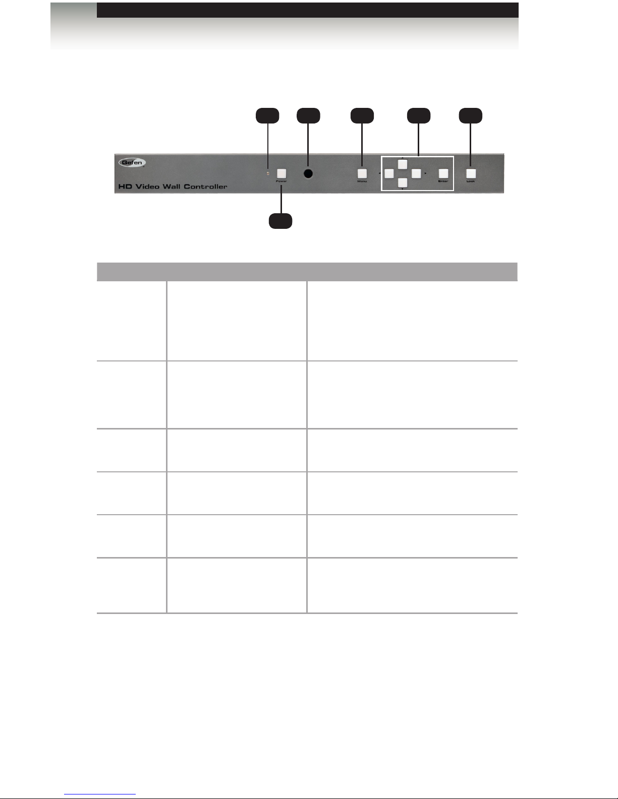
Front
ID Name Description
1 Power indicator This LED glows bright blue when the unit
is connected to an AC outlet and the unit is
powered on.
In standby mode, this LED glows bright red.
2 Power Press this button to toggle between
power-on and standby mode. This button
will glow bright blue when the unit is
powered on.
3 IR sensor This IR sensor receives commands from the
included IR remote control unit.
4 Menu Press this button to display the On-Screen
Display (OSD) menu system.
5 ▲,◄,▼,►, Enter These buttons are used to make selections
from within the OSD menu system.
6 Lock Press this button to lock the front panel. This
button will glow bright blue when this button
is enabled.
Getting Started
Panel Layout
3
1
4 5
2
6
Page 13
page | 3
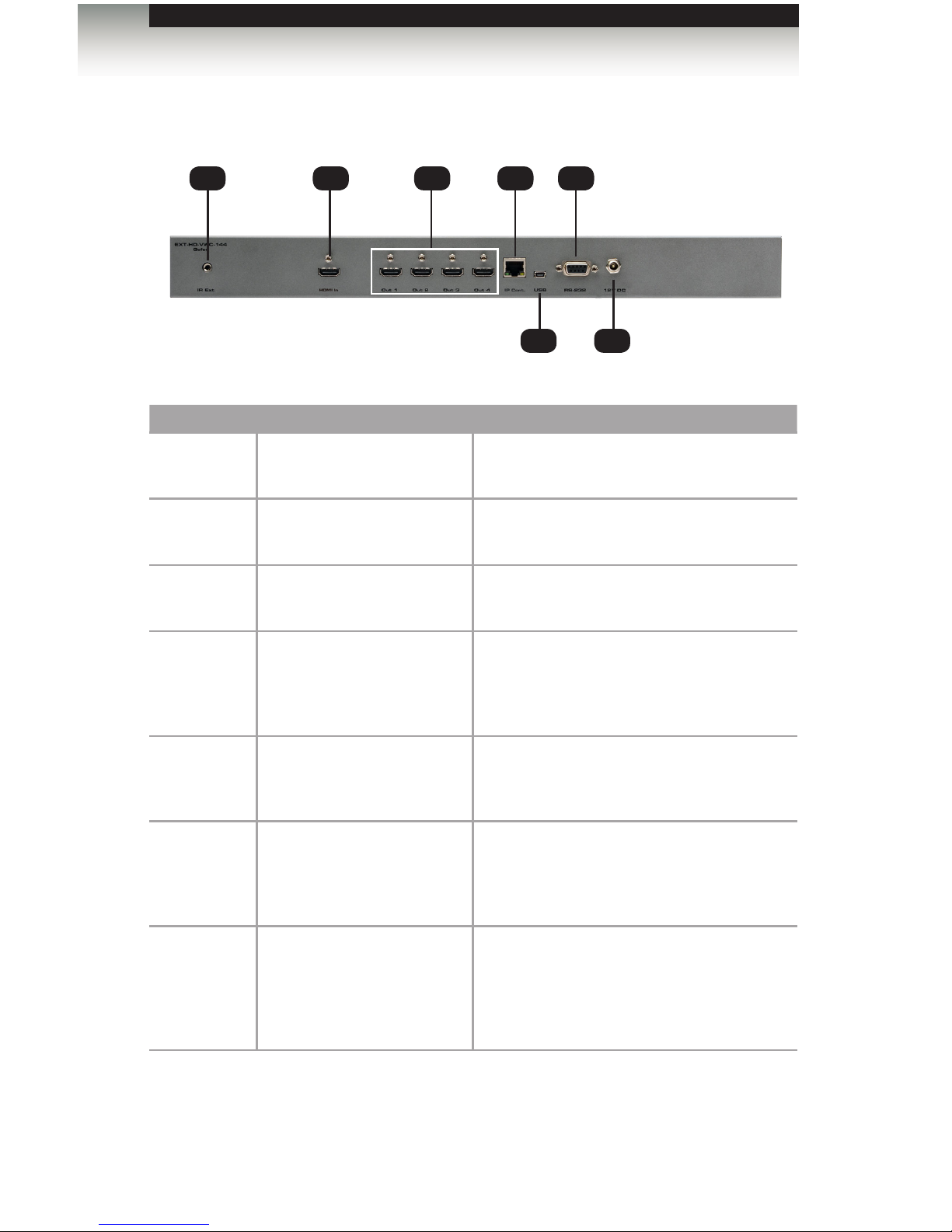
Back
ID Name Description
1 IR Ext Connect the included IR Extender (Gefen
part no. EXT-RMT-EXTIRN) to this port.
2 HDMI In Connect the included HDMI cable between
this port and the Hi-Def source.
3 Out (1 - 4) Connect up to four HDTV displays to these
HDMI outputs.
4 IP Control Connect an Ethernet cable between
this jack and a LAN to use IP control.
See RS-232 and IP Conguration for more
information on setting up IP control.
5 USB This mini USB port is used for upgrading
the rmware. See Upgrading the Firmware
for more information.
6 RS-232 Connect the included RS-232 cable from this
port to an RS-232 device. See RS-232 and
IP Conguration for more information on
setting up RS-232.
7 12V DC Connect the included 12V DC power
supply from this power receptacle to an
available AC electrical outlet. Do not
overtighten the locking connector on the
power receptacle.
Getting Started
2 31 4 6
5 7
Panel Layout
Page 14
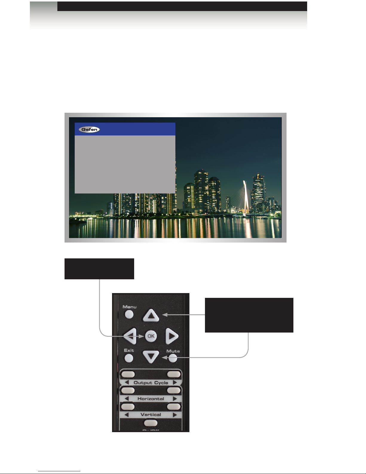
page | 4
Top
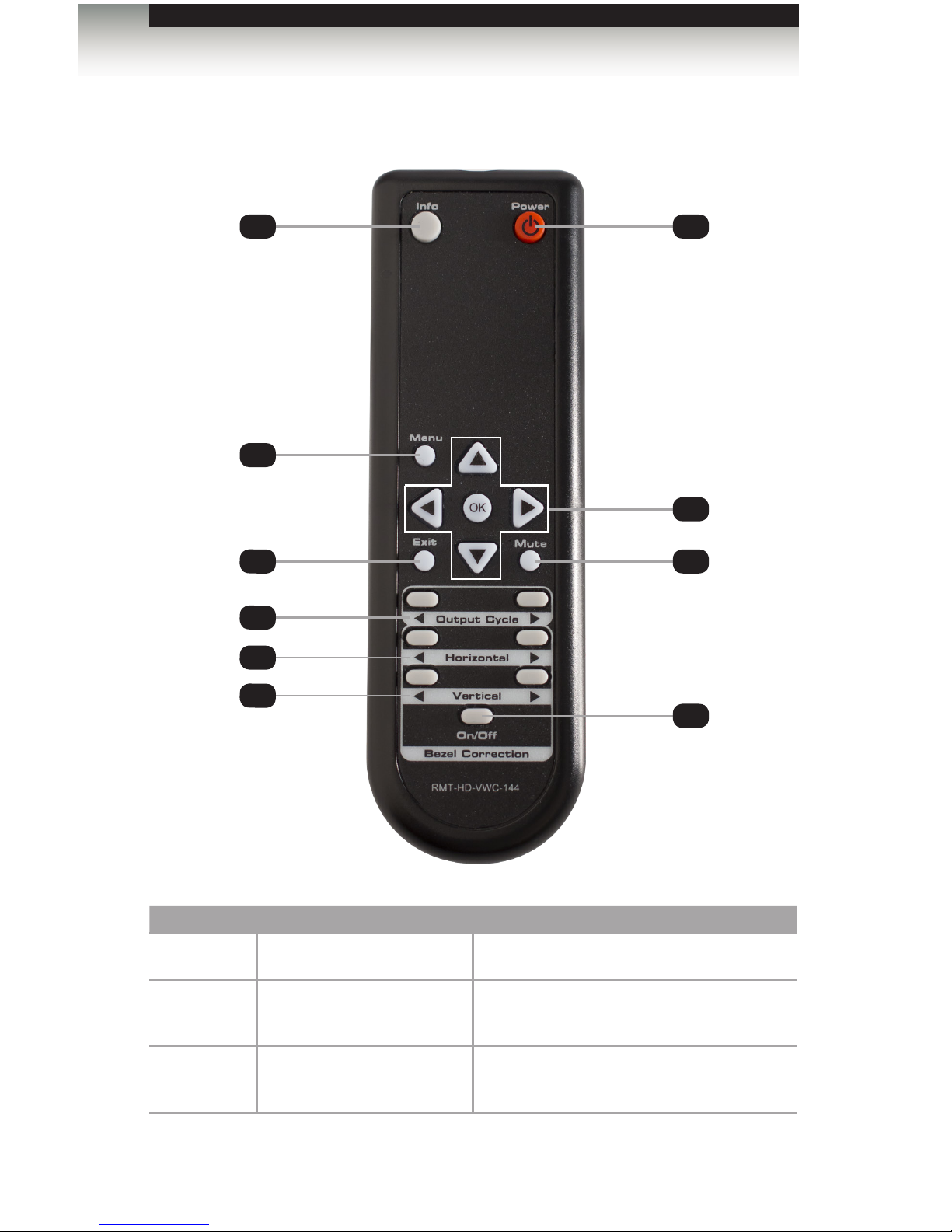
ID Name Description
1 Info Used to toggle notications on all outputs.
2 Menu Press this button to display the built-in
menu system.
3 Exit Press this button to exit the main menu or
exit from sub-menus.
IR Remote Control Unit
1
2
3
4
5
6
7
8
9
10
Getting Started
Page 15

page | 5
IR Remote Control Unit
4 Output Cycle (◄ / ► ) Press these buttons to cycle through the
available output resolutions. For a list of
available resolutions, refer to the #set_
output command.
5 Horizontal (◄ / ► ) Press these buttons to adjust the horizontal
positioning of the image. Press the ◄ button
to move the image to the left. Press the ►
button to move the image to the right.
6 Vertical (◄ / ► ) Press these buttons to adjust the vertical
positioning of the image. Press the ◄ button
to move the image up. Press the ► button
to move the image down.
7 Power Press this button to toggle the power state of
the HD Video Wall Controller.
8 ◄ /►/▲/▼/OK Used to access and change features within
the menu system. Use the arrow buttons
to move around within the menu system or
change a value. Press the OK button to
make a selection within the menu system.
9 Mute Mutes the audio on all outputs.
10 Bezel Correction (On / Off) Used to adjust the bezel correction.
Getting Started
Page 16
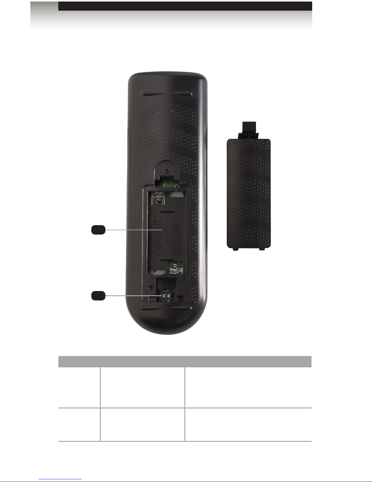
page | 6
Bottom
ID Name Description
1 Battery slot
(shown without batteries)
Holds the batteries for operating the
IR remote. Use only 1.5V “AAA”-type
batteries. See Installing the Batteries for
more information.
2 DIP switch bank Use these DIP switches to set the IR
channel of the remote. See Setting the IR
Channel for details.
IR Remote Control Unit
Battery Cover
1
2
Getting Started
Page 17
page | 7
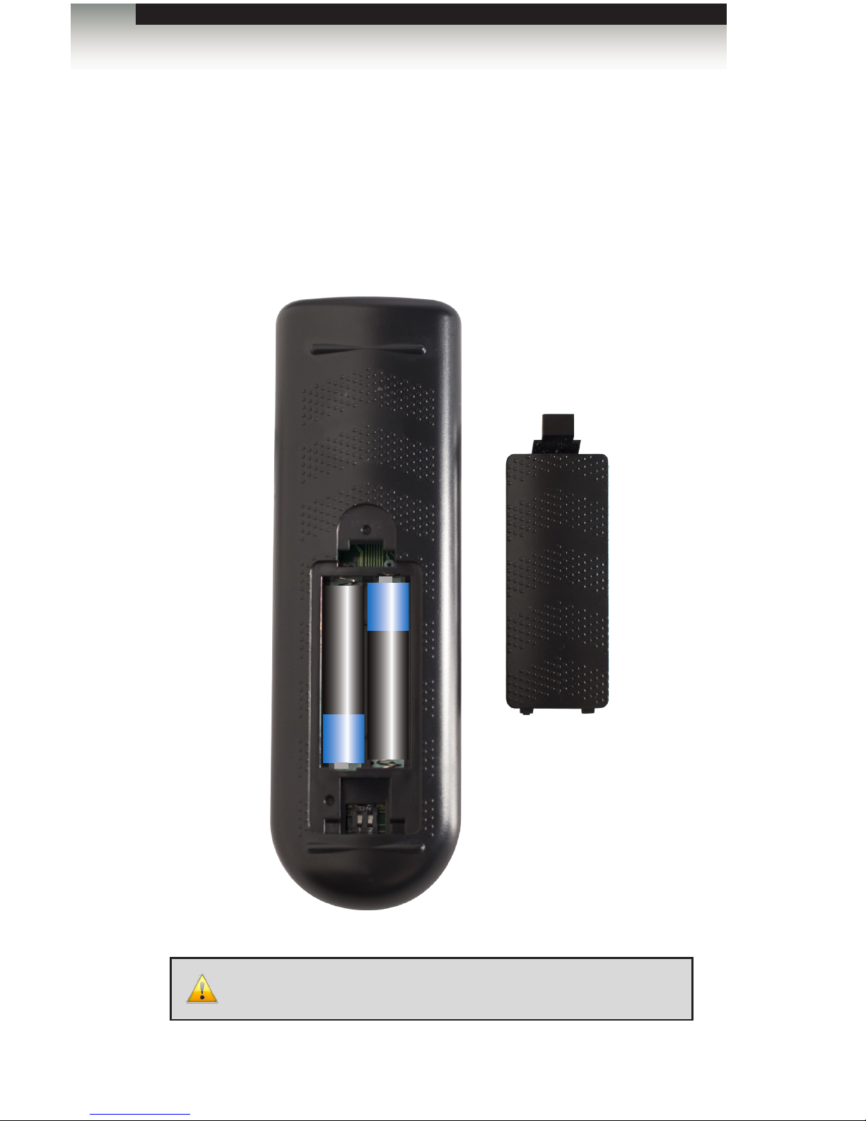
Installing the Batteries
1. Remove the battery cover on the bottom of the IR remote control unit.
2. Make sure that the batteries are installed with the correct polarity, as shown in the
illustration, below. Always use two 1.5V AAA-type batteries.
3. Replace the battery cover.
IR Remote Control Unit
WARNING: Risk of explosion if battery is replaced by an incorrect
type. Dispose of used batteries according to the instructions.
Battery Cover
_
+
_
+
Getting Started
Page 18
page | 8
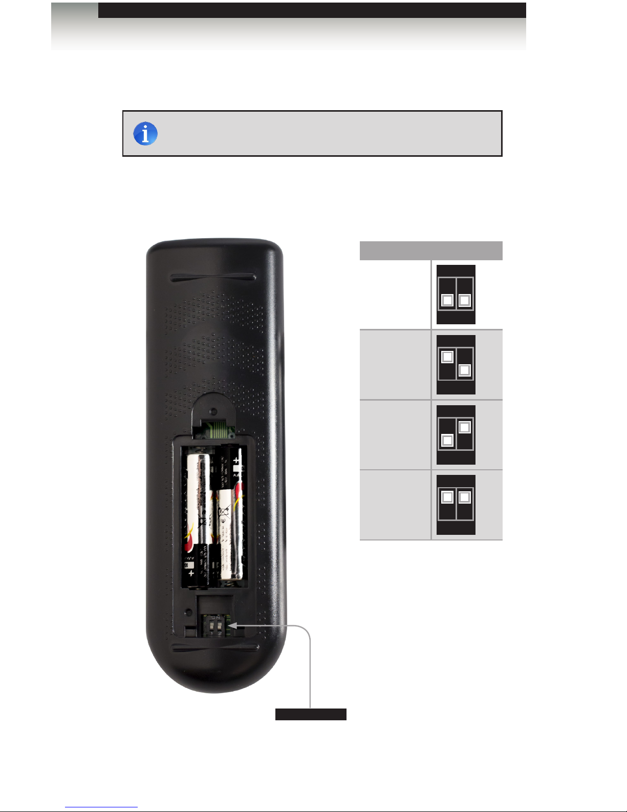
Setting the IR Channel
Make sure that the IR remote is set to channel 0 (see the diagram, below). Otherwise, the
HD Video Wall Controller will not work with the IR remote. Future releases of the rmware
will allow the IR channel to be changed.
IR Channel DIP settings
0
1 2
ON
1
(not used)
1 2
ON
1 2
2
(not used)
1 2
ON
3
(not used)
1 2
ON
IR Remote Control Unit
DIP switches
Getting Started
NOTE: The IR remote must be set to channel 0 in order to
communicate with the HD Video Wall Controller.
Page 19
page | 9
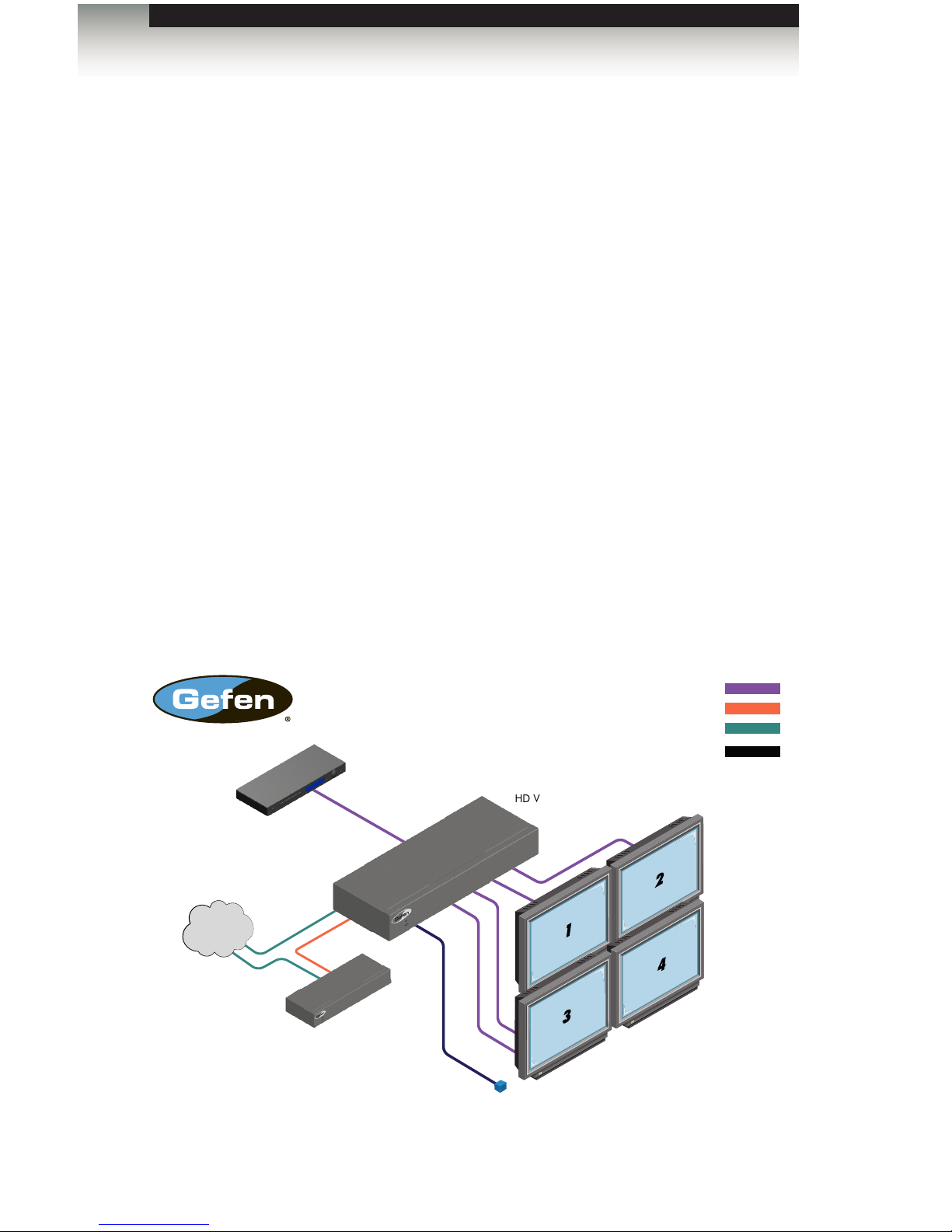
Connecting the HD Video Wall Controller
1. Use the included HDMI cable to connect the Hi-Def source to the HDMI In port on the
HD Video Wall Controller.
2. Connect up to four HDTV displays to the Out (1 - 4) ports on the HD Video Wall
Controller.
3. OPTIONAL: To use IP / UDP / Telnet control, connect an Ethernet cable from the IP
Control port on the HD Video Wall Controller to a Local Area Network (LAN).
4. OPTIONAL: To extend the range of the IR sensor, connect the included IR extender
to the IR Ext port on the HD Video Wall Controller.
5. Connect the included 12V DC locking power supply to the power receptacle on the
Video Wall Controller. Do not overtighten the locking power connector.
6. Connect the power supply to an available electrical outlet.
Sample Wiring Diagram
Installation
IP Control
Network
EXT-PACS
EXT-HD-VWC-144
HDMI CABLE
RS-232 CABLE
HD Displays
HD Video Wall Controller
HD Source
CAT-5 CABLE
IR EXTENDER
Getting Started
Page 20

Page 21

HD
Video Wall
Controller
02 Operating the
HD Video Wall Controller
Introduction.......................................................................................................... 12
Standby Mode ............................................................................................. 12
Turning on the HD Video Wall Controller .................................................... 12
Using IR Control .......................................................................................... 13
Using the Menu System ...................................................................................... 14
Accessing the Menu System ....................................................................... 14
Setting the Output Resolution ..................................................................... 17
Adjusting the Contrast ................................................................................. 19
Adjusting the Brightness ............................................................................. 21
Adjusting the Saturation .............................................................................. 23
Adjusting the Hue ........................................................................................ 25
Bezel Correction .......................................................................................... 27
OSD Settings .............................................................................................. 30
EDID Management ...................................................................................... 34
Changing the IP Settings ............................................................................ 36
Changing the Telnet Settings ...................................................................... 39
Changing the UDP Settings ........................................................................ 41
System Settings .......................................................................................... 44
Page 22
page | 12
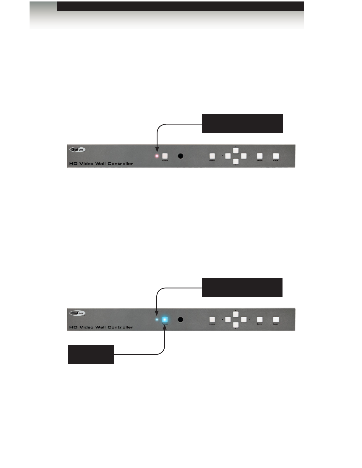
Standby Mode
The multi-color LED next to the Power button, on the front panel, indicates the power state
of the HD Video Wall Controller. In standby mode, power is being supplied to the HD Video
Wall Controller but the unit is not turned on. This LED will be red and remain illuminated as
long as the unit is in standby mode. If this LED does not illuminate, check the connection
between the power receptacle on the HD Video Wall Controller and the AC outlet.
Turning on the HD Video Wall Controller
Once the HD Video Wall Controller is in standby mode, press the Power button to power on
the unit. The Power button and the LED indicator will turn blue and both remain illuminated
as long as the unit is powered on. To power off the HD Video Wall Controller and return to
standby mode, press the Power button again.
Operating the HD Video Wall Controller
Introduction
Red LED indicates that
matrix is in standby mode
Blue LED indicates that
matrix is powered ON
Power button
is illuminated
Page 23
page | 13
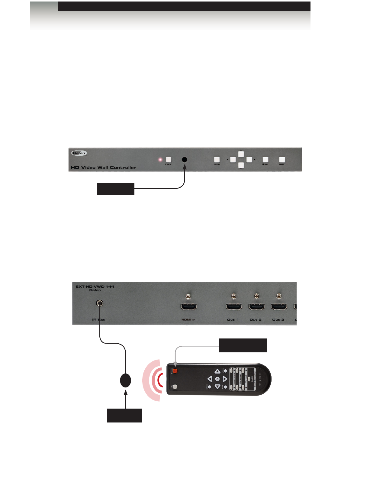
Using IR Control
The HD Video Wall Controller can also be powered-ON or placed in standby mode by using
the included IR remote control.
When the HD Video Wall Controller is in standby mode, press the Power button to powerON the unit. To power-OFF the unit and place it in standby mode, press the Power button
again. Always make sure to point the IR remote at the IR sensor on the front panel.
The IR remote control also provides full control of all features. See Accessing the Menu
System for more information.
There may be situations where the IR sensor is blocked by a cabinet or other mounting
device. In this case, an IR extender (Gefen part no. EXT-RMT-EXTIRN) can be connected
to the IR Ext port on the back of the HD Video Wall Controller. The sensor on the IR
extender behaves exactly like the sensor on the front panel of the matrix. Always point the
IR remote control unit in the direction of the IR sensor.
Operating the HD Video Wall Controller
IR sensor
Introduction
IR extender
IR remote
IR sensor
Power button
Page 24
page | 14
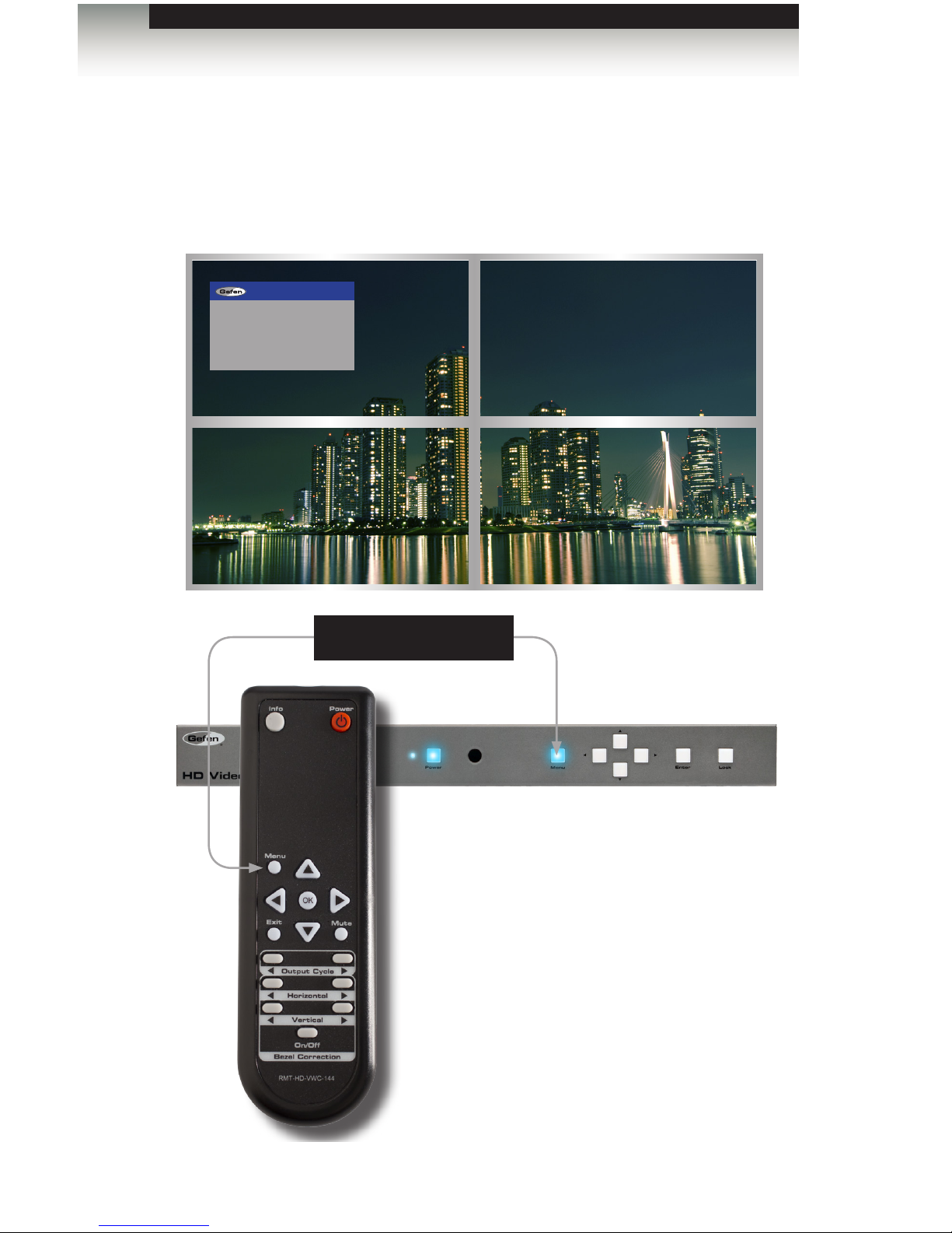
Accessing the Menu System
The HD Video Wall Controller uses a built-in menu system to manage and control all video
features. To access the menu system, press the Menu button on the front panel or on the
included IR remote control.
Operating the HD Video Wall Controller
Using the Menu System
Press the Menu button
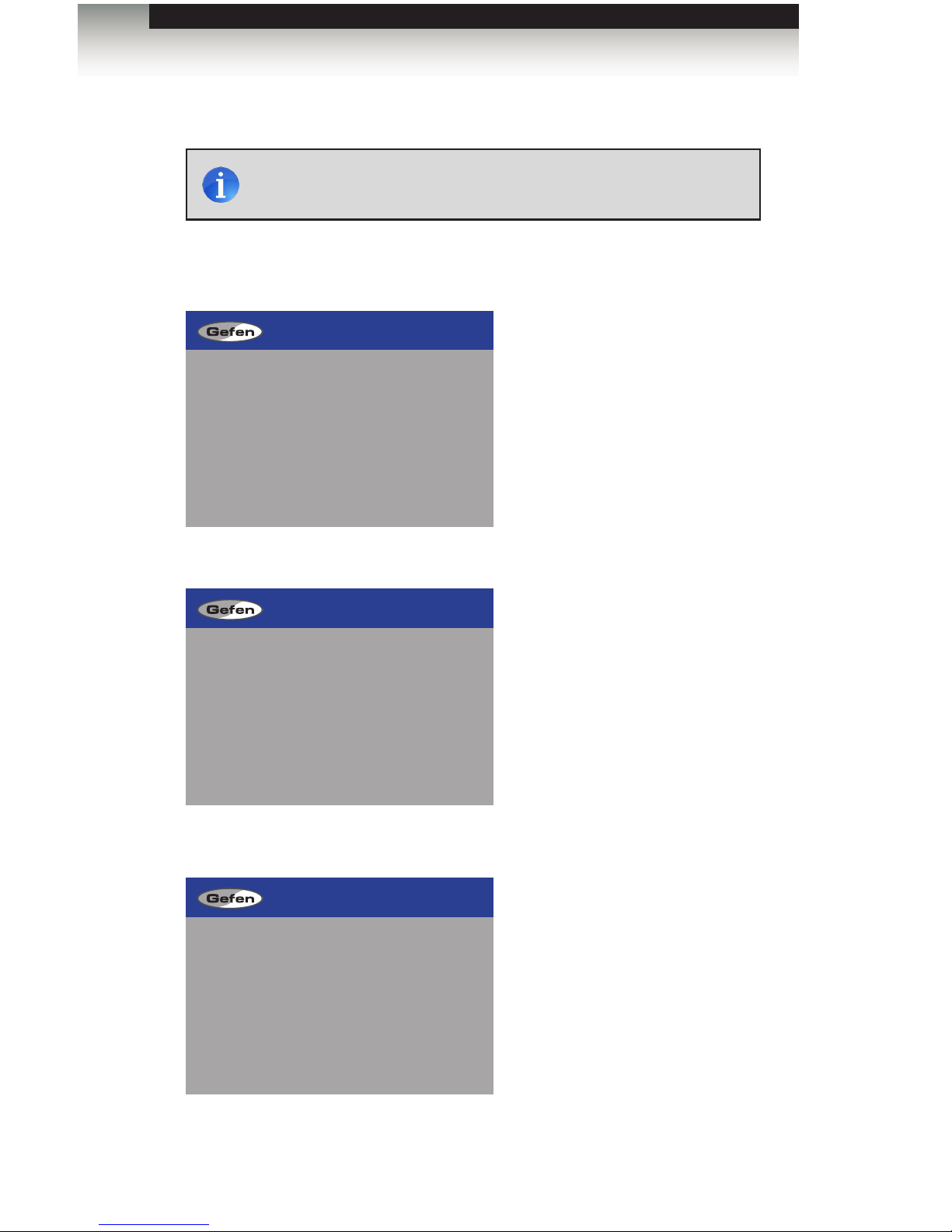
After pressing the Menu button on the front
panel, the Menu button will remain illuminated
as long as the menu system is displayed on the
screen. By default, the menu system will be
displayed within the top-left display.
The time-out value (duration) for the menu
system can be changed in the OSD Settings
page of the menu system.
MAIN
SETUP
NETWORK
SYSTEM
EXIT
Page 25
page | 15
Operating the HD Video Wall Controller
Using the Menu System
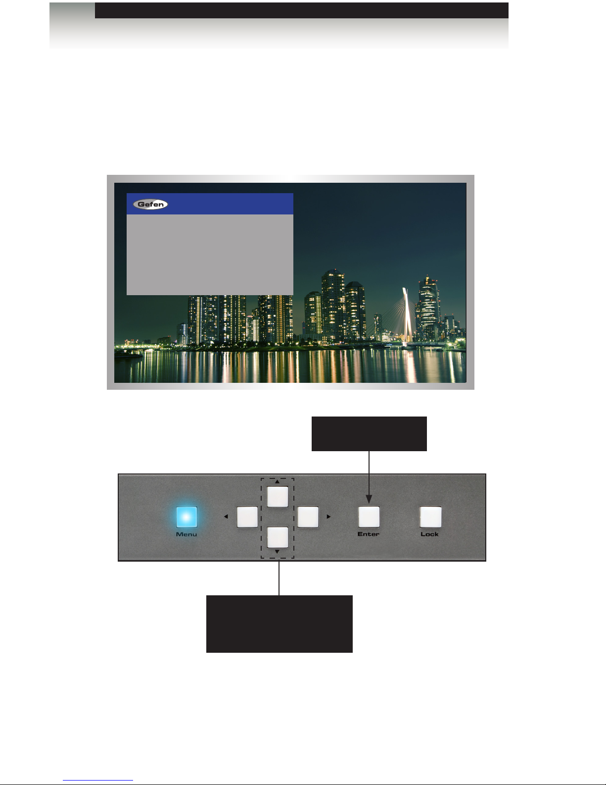
Using the Front Panel Buttons
Use the ◄, ►, ▲, and ▼ buttons on the front panel to move around within the menu
system. Press the ▲ and ▼ buttons to move up and down. Press the ◄ or ► buttons
to change the value of the current selection. Press the Enter button to make the desired
selection. The current selection will be highlighted in green.
Press the ▲ and ▼ buttons
to move up and down within
the menu system
Press to select the
highlighted menu item
MAIN
SETUP
NETWORK
SYSTEM
EXIT
Page 26
page | 16
Using the IR Remote Control
The IR remote control has buttons which represent the controls on the front panel.
Use the ◄, ►, ▲, and ▼ buttons to move around within the menu system. Press the ▲
and ▼ buttons to move up and down. Press the ◄ or ► buttons to change the value of
the current selection. Press the OK button to make the desired selection. The current
selection will be highlighted in green.
Press the ▲ and ▼ buttons
to move up and down within
the menu system
Press to select the
highlighted menu item
Operating the HD Video Wall Controller
Using the Menu System
SETUP
NETWORK
SYSTEM
EXIT
I/O SETUP
Page 27
page | 17
Setting the Output Resolution
1. Press the Menu button on the front panel or on the IR remote control. The menu
system will be displayed.
2. Press the Enter button. If using the IR remote, press the OK button.
3. Press the Enter button again to enter the Output Resolution menu. If using the IR
remote, press the OK button.
OUTPUT RESOLUTION
PICTURE SETTINGS
BEZEL CORRECTION
OSD SETTINGS
EDID
BACK
EXIT
I/O SETUP
480p 1600x900
576p 1600x1200
720p50 1680x1050
720p60 1920x1200
1080p24 NATIVE
1080p50 BACK
1080p60 EXIT
1024x768
1280x800
1280x1024
1366x768
1440x900
OUTPUT RESOLUTION
SETUP
NETWORK
SYSTEM
EXIT
I/O SETUP
Operating the HD Video Wall Controller
Using the Menu System
NOTE: When changing this setting, make sure that all connected
displays can support the selected output resolution.
Page 28

page | 18
Operating the HD Video Wall Controller
Using the Menu System
4. Use the ▲ or ▼ buttons to highlight the desired output resolution.
5. Press the Enter button to apply the selected resolution. If using the IR remote, press
the OK button.
480p 1600x900
576p 1600x1200
720p50 1680x1050
720p60 1920x1200
1080p24 NATIVE
1080p50 BACK
1080p60 EXIT
1024x768
1280x800
1280x1024
1366x768
1440x900
OUTPUT RESOLUTION
Page 29

page | 19
Adjusting the Contrast
1. Press the Menu button on the front panel or on the IR remote control. The menu
system will be displayed.
2. Press the Enter button. If using the IR remote, press the OK button.
3. Use the ▲ or ▼ buttons to select Picture Settings.
4. Press the Enter button. If using the IR remote, press the OK button.
The Contrast option should already be highlighted in green.
OUTPUT RESOLUTION
PICTURE SETTINGS
BEZEL CORRECTION
OSD SETTINGS
EDID
BACK
EXIT
I/O SETUP
SETUP
NETWORK
SYSTEM
EXIT
I/O SETUP
Operating the HD Video Wall Controller
Using the Menu System
PICTURE SETTINGS
CONTRAST
BRIGHTNESS
SATURATION
HUE
OUT 4
OUT 3
OUT 2
OUT 1
RESET
RESET ALL
BACK
EXIT
Page 30

page | 20
5. Press the Enter button to select the Contrast option. If using the IR remote,
press the OK button.
The Contrast option will be highlighted in orange.
6. Use the ▲ or ▼ buttons to highlight the desired output.
7. Press the Enter button to select the highlighted output. If using the IR remote,
press the OK button.
8. Use the ◄ or ► buttons to change the contrast value.
9. Press the Enter button to accept the current value. If using the IR remote,
press the OK button.
10. To reset the contrast to default values on all outputs, use the Reset Contrast option.
Operating the HD Video Wall Controller
Using the Menu System
PICTURE SETTINGS
CONTRAST
BRIGHTNESS
SATURATION
HUE
OUT 4 50
OUT 3 50
OUT 2 50
OUT 1 50
RESET CONTRAST
RESET ALL
BACK
EXIT
PICTURE SETTINGS
CONTRAST
BRIGHTNESS
SATURATION
HUE
OUT 4 50
OUT 3 50
OUT 2 50
OUT 1 50
RESET CONTRAST
RESET ALL
BACK
EXIT
Page 31

page | 21
Menu System
Operating the HD Video Wall Controller
Adjusting the Brightness
1. Press the Menu button on the front panel or on the IR remote control. The menu
system will be displayed.
2. Press the Enter button. If using the IR remote, press the OK button.
3. Use the ▲ or ▼ buttons to select Picture Settings.
4. Press the Enter button. If using the IR remote, press the OK button.
5. Use the ▲ or ▼ buttons to highlight Brightness.
OUTPUT RESOLUTION
PICTURE SETTINGS
BEZEL CORRECTION
OSD SETTINGS
EDID
BACK
EXIT
I/O SETUP
SETUP
NETWORK
SYSTEM
EXIT
I/O SETUP
PICTURE SETTINGS
CONTRAST
BRIGHTNESS
SATURATION
HUE
OUT 4
OUT 3
OUT 2
OUT 1
RESET
RESET ALL
BACK
EXIT
Page 32

page | 22
6. Press the Enter button again to select the Brightness option. If using the IR remote,
press the OK button.
The Brightness option will be highlighted in orange.
7. Use the ▲ or ▼ buttons to highlight the desired output.
8. Press the Enter button to select the highlighted output. If using the IR remote,
press the OK button.
9. Use the ◄ or ► buttons to change the brightness value.
10. Press the Enter button to accept the current value. If using the IR remote,
press the OK button.
11. To reset the brightness to default values on all outputs, use the Reset Brightness
option.
Operating the HD Video Wall Controller
Using the Menu System
PICTURE SETTINGS
CONTRAST
BRIGHTNESS
SATURATION
HUE
OUT 4 50
OUT 3 50
OUT 2 50
OUT 1 50
RESET CONTRAST
RESET ALL
BACK
EXIT
PICTURE SETTINGS
CONTRAST
BRIGHTNESS
SATURATION
HUE
OUT 4 57
OUT 3 42
OUT 2 50
OUT 1 50
RESET BRIGHTNESS
RESET ALL
BACK
EXIT
Page 33

page | 23
Menu System
Operating the HD Video Wall Controller
Adjusting the Saturation
1. Press the Menu button on the front panel or on the IR remote control. The menu
system will be displayed.
2. Press the Enter button. If using the IR remote, press the OK button.
3. Use the ▲ or ▼ buttons to highlight Picture Settings.
4. Press the Enter button. If using the IR remote, press the OK button.
5. Use the ▲ or ▼ buttons to highlight Saturation.
OUTPUT RESOLUTION
PICTURE SETTINGS
BEZEL CORRECTION
OSD SETTINGS
EDID
BACK
EXIT
I/O SETUP
SETUP
NETWORK
SYSTEM
EXIT
I/O SETUP
PICTURE SETTINGS
CONTRAST
BRIGHTNESS
SATURATION
HUE
OUT 4
OUT 3
OUT 2
OUT 1
RESET
RESET ALL
BACK
EXIT
Page 34

page | 24
Menu System
Operating the HD Video Wall Controller
6. Press the Enter button again to select the Saturation option. If using the IR remote,
press the OK button.
The Saturation option will be highlighted in orange.
7. Use the ▲ or ▼ buttons to highlight the desired output.
8. Press the Enter button to select the highlighted output. If using the IR remote,
press the OK button.
9. Use the ◄ or ► buttons to change the saturation value.
10. Press the Enter button to accept the current value. If using the IR remote,
press the OK button.
11. To reset the saturation to default values on all outputs, use the Reset Saturation
option.
PICTURE SETTINGS
CONTRAST
BRIGHTNESS
SATURATION
HUE
OUT 4 50
OUT 3 50
OUT 2 50
OUT 1 50
RESET SATURATION
RESET ALL
BACK
EXIT
PICTURE SETTINGS
CONTRAST
BRIGHTNESS
SATURATION
HUE
OUT 4 31
OUT 3 50
OUT 2 50
OUT 1 50
RESET SATURATION
RESET ALL
BACK
EXIT
Page 35

page | 25
Menu System
Operating the HD Video Wall Controller
Adjusting the Hue
1. Press the Menu button on the front panel or on the IR remote control. The menu
system will be displayed.
2. Press the Enter button. If using the IR remote, press the OK button.
3. Use the ▲ or ▼ buttons to highlight Picture Settings.
4. Press the Enter button. If using the IR remote, press the OK button.
5. Use the ▲ or ▼ buttons to highlight Hue.
OUTPUT RESOLUTION
PICTURE SETTINGS
BEZEL CORRECTION
OSD SETTINGS
EDID
BACK
EXIT
I/O SETUP
SETUP
NETWORK
SYSTEM
EXIT
I/O SETUP
PICTURE SETTINGS
CONTRAST
BRIGHTNESS
SATURATION
HUE
OUT 4
OUT 3
OUT 2
OUT 1
RESET
RESET ALL
BACK
EXIT
Page 36

page | 26
6. Press the Enter button again to select the Hue option. If using the IR remote, press
the OK button.
The Hue option will be highlighted in orange.
7. Use the ▲ or ▼ buttons to highlight the desired output.
8. Press the Enter button to select the highlighted output. If using the IR remote,
press the OK button.
9. Use the ◄ or ► buttons to change the hue value.
10. Press the Enter button to accept the current value. If using the IR remote,
press the OK button.
11. To reset the hue to default values on all outputs, use the Reset Hue option.
PICTURE SETTINGS
CONTRAST
BRIGHTNESS
SATURATION
HUE
OUT 4 50
OUT 3 50
OUT 2 50
OUT 1 50
RESET HUE
RESET ALL
BACK
EXIT
PICTURE SETTINGS
CONTRAST
BRIGHTNESS
SATURATION
HUE
OUT 4 28
OUT 3 50
OUT 2 50
OUT 1 50
RESET HUE
RESET ALL
BACK
EXIT
Menu System
Operating the HD Video Wall Controller
Page 37

page | 27
Menu System
Operating the HD Video Wall Controller
Bezel Correction
Bezel correction is necessary to compensate for the bezel-thickness of each display.
Without adjustment, the picture will appear distorted.
1. Press the Menu button on the front panel or on the IR remote control. The menu
system will be displayed.
2. Press the Enter button. If using the IR remote, press the OK button.
3. Use the ▲ or ▼ buttons to highlight Bezel Correction.
4. Press the Enter button. If using the IR remote, press the OK button.
OUTPUT RESOLUTION
PICTURE SETTINGS
BEZEL CORRECTION
OSD SETTINGS
EDID
BACK
EXIT
I/O SETUP
SETUP
NETWORK
SYSTEM
EXIT
I/O SETUP
BEZEL CORRECTION
CORRECTION OFF
H CORRECTION 0
V CORRECTION 0
BACK
EXIT
Page 38

page | 28
6. Press the Enter button again to select the Correction option. If using the IR remote,
press the OK button.
The On / Off option will be highlighted in orange.
7. Use the ◄ or ► buttons to enable (On) or disable (Off) bezel correction.
8. Press the Enter button to select the desired option. The current state will be highlighted in
white and the H Correction and V Correction options will become available.
9. Use the ▲ or ▼ buttons to highlight H Correction or V Correction.
10. Press the Enter button to select the desired option. The current value will be
highlighted in orange.
Menu System
Operating the HD Video Wall Controller
BEZEL CORRECTION
CORRECTION OFF
H CORRECTION 0
V CORRECTION 0
BACK
EXIT
BEZEL CORRECTION
CORRECTION ON
H CORRECTION 0
V CORRECTION 0
BACK
EXIT
BEZEL CORRECTION
CORRECTION ON
H CORRECTION 0
V CORRECTION 0
BACK
EXIT
Page 39

page | 29
11. Use the ◄ or ► buttons to change the value.
12. Press the Enter button to accept the current value.
Menu System
Operating the HD Video Wall Controller
BEZEL CORRECTION
CORRECTION ON
H CORRECTION 0
V CORRECTION 12
BACK
EXIT
Page 40

page | 30
Menu System
OSD Settings
The OSD Settings menu controls how the OSD is displayed.
1. Press the Menu button on the front panel or on the IR remote control. The menu
system will be displayed.
2. Press the Enter button. If using the IR remote, press the OK button.
3. Use the ▲ or ▼ buttons to highlight the option to change. The Position option will be
highlighted, automatically.
4. Once the desired option is highlighted, press the Enter button to select it. If using the
IR remote control, press the OK button.
When an option is selected, its current value will be highlighted in orange.
OSD SETTINGS
POSITION LEFT T
H OFFSET 10
V OFFSET 10
MENU TIMEOUT OFF
INFO.TIMEOUT 8
INFO.DISPLAY ON
BRIEF INFO ON
BACK
EXIT
OSD SETTINGS
POSITION LEFT T
H OFFSET 10
V OFFSET 10
MENU TIMEOUT OFF
INFO.TIMEOUT 8
INFO.DISPLAY ON
BRIEF INFO ON
BACK
EXIT
Operating the HD Video Wall Controller
SETUP
NETWORK
SYSTEM
EXIT
I/O SETUP
Page 41

page | 31
Menu System
5. Use the ◄ or ► buttons to change the current value.
6. Press the Enter button to accept the current changes. If using the IR remote control,
press the OK button.
Position
Assigns the display where the OSD will be displayed, when the Menu button is pressed.
H Offset
The horizontal offset of the OSD, as it appears on the display.
Operating the HD Video Wall Controller
SETUP
NETWORK
SYSTEM
EXIT
I/O SETUP
SETUP
NETWORK
SYSTEM
EXIT
I/O SETUP
SETUP
NETWORK
SYSTEM
EXIT
I/O SETUP
SETUP
NETWORK
SYSTEM
EXIT
I/O SETUP
LEFT T = Left Top
LEFT B = Left Bottom
RIGHT T = Right Top
RIGHT B = Right Bottom
SETUP
NETWORK
SYSTEM
EXIT
I/O SETUP
Page 42

page | 32
Menu System
V Offset
The vertical offset of the OSD, as it appears on the display.
Menu Timeout
Once the Menu button is pressed, the OSD will appear. Timeout is the duration, in
seconds, when the OSD will be automatically dismissed. If set to Off, then the OSD must
be hidden manually by pressing the Menu button.
Info Timeout
By default, each display will show an information (info) window. This window displays the
input and output resolution. Menu Timeout is the duration, in seconds, of the OSD before it
is automatically hidden.
Operating the HD Video Wall Controller
SETUP
NETWORK
SYSTEM
EXIT
I/O SETUP
WALL 720p60
IN 720p60
Page 43

page | 33
Menu System
Info Display
Enables (On) or disables (Off) the Info window. If set to Off, the Info window is never
displayed.
Brief Info
This option controls what is displayed when Info Display set to On. If Brief Info is set to
On, then only the In and Out routing information is displayed. If Brief Info is set to Off,
then the resolution information is also displayed.
Operating the HD Video Wall Controller
Page 44

page | 34
EDID Management
1. Press the Menu button on the front panel or on the IR remote control. The menu
system will be displayed.
2. Press the Enter button. If using the IR remote, press the OK button.
3. Use the ▲ or ▼ buttons to highlight the EDID option.
4. Press the Enter button to display the EDID menu. If using the IR remote,
press the OK button.
Menu System
EDID
LOCK EDID OFF
COPY TO INPUT
OUTPUT 1 COPY
OUTPUT 2 COPY
OUTPUT 3 COPY
OUTPUT 4 COPY
1080P 2CH COPY
1080P MULTI CH COPY
BACK
EXIT
Operating the HD Video Wall Controller
SETUP
NETWORK
SYSTEM
EXIT
I/O SETUP
OUTPUT RESOLUTION
PICTURE SETTINGS
BEZEL CORRECTION
OSD SETTINGS
EDID
BACK
EXIT
I/O SETUP
Page 45

page | 35
5. Press the Select button to select the Lock EDID option.
6. Use the ◄ or ► buttons to change the value of the Lock EDID option.
7. Press the Select button to accept the Lock EDID value.
Selecting an EDID
1. Make sure the Lock EDID option is set to Off.
2. Use the ▲ or ▼ buttons to highlight the desired output, containing the EDID to be
copied to the input. The 1080p 2CH or 1080p Multi Ch EDID can also be selected.
When selecting an EDID, make sure that all displays can support the same audio
and video capabilities
3. Press the Enter button to accept the current output selection. If using the IR remote,
press the OK button.
4. The display will ash momentarily. The EDID from the selected output will be copied
to the input and will be used by all outputs.
Menu System
EDID
LOCK EDID OFF
COPY TO INPUT
OUTPUT 1 COPY
OUTPUT 2 COPY
OUTPUT 3 COPY
OUTPUT 4 COPY
1080P 2CH COPY
1080P MULTI CH COPY
BACK
EXIT
EDID
LOCK EDID ON
COPY TO INPUT
OUTPUT 1 COPY
OUTPUT 2 COPY
OUTPUT 3 COPY
OUTPUT 4 COPY
1080P 2CH COPY
1080P MULTI CH COPY
BACK
EXIT
Operating the HD Video Wall Controller
Page 46

page | 36
Changing the IP Settings
1. Press the Menu button on the front panel or on the IR remote control. The menu
system will be displayed.
2. Use the ▲ or ▼ buttons to highlight the Network option.
3. Press the Enter button to display the Network menu. If using the IR remote,
press the OK button.
4. Press the Enter button again to display the IP Settings menu. If using the IR remote,
press the OK button.
Menu System
Operating the HD Video Wall Controller
IP SETTINGS
TELNET SETTINGS
UDP SETTINGS
BACK
EXIT
NETWORK
IP MODE STATIC
TYPE SELECT IP
BYTE1 192
BYTE2 168
BYTE3 1
BYTE4 72
RE-LINK
TIMEOUT(Min.) 10
HTTP PORT 80
RESTORE DEFAULT OFF
BACK
EXIT
STATIC IP NOT LINKED
NETWORK
SETUP
NETWORK
SYSTEM
EXIT
I/O SETUP
Page 47

page | 37
5. Use the ▲ or ▼ buttons to highlight the option to change. The IP Mode option will be
highlighted, automatically.
6. Once the desired option is highlighted, press the Enter button to select it. If using the
IR remote control, press the OK button.
When an option is selected, its current value will be highlighted in orange.
7. Use the ◄ or ► buttons to change the current value.
8. Press the Enter button to accept the current changes. If using the IR remote control,
press the OK button.
IP Mode
Set this option to either Static or DHCP. If using the Static option, the IP address must be
specied. Use the Byte1, Byte2, Byte3, and Byte4 options to set each of the digits in the IP
address, subnet mask, and gateway.
Type Select
Use this option to switch between the IP address (IP), subnet mask (Mask), and gateway
(Gate).
Byte
Use the Byte1, Byte2, Byte3, and Byte4 options to set each of the digits in the IP address,
subnet mask, and gateway.
Re-link
Use this option to attempt to re-link to the network using the current IP settings.
Menu System
IP MODE STATIC
TYPE SELECT IP
BYTE1 192
BYTE2 168
BYTE3 1
BYTE4 72
RE-LINK
TIMEOUT(Min.) 10
HTTP PORT 80
RESTORE DEFAULT OFF
BACK
EXIT
STATIC IP NOT LINKED
NETWORK
Operating the HD Video Wall Controller
Page 48

page | 38
Timeout
Sets the time-out period (in seconds) when using the Re-Link option to link with the network
using the current IP settings.
HTTP Port
Sets the HTTP listening port for the HD Video Wall Controller.
Restore Default
This option will reset the default IP settings for the HD Video Wall Controller.
IP MODE STATIC
TYPE SELECT IP
BYTE1 192
BYTE2 168
BYTE3 1
BYTE4 72
RE-LINK
TIMEOUT(Min.) 10
HTTP PORT 80
RESTORE DEFAULT OFF
BACK
EXIT
STATIC IP NOT LINKED
NETWORK
Menu System
Operating the HD Video Wall Controller
Page 49

page | 39
Changing the Telnet Settings
1. Press the Menu button on the front panel or on the IR remote control. The menu
system will be displayed.
2. Use the ▲ or ▼ buttons to highlight the Network option.
3. Press the Enter button to display the Network menu. If using the IR remote,
press the OK button.
4. Use the ▲ or ▼ buttons to highlight the Telnet Settings option.
5. Press the Enter button again to display the Telnet Settings menu. If using the IR
remote, press the OK button.
IP SETTINGS
TELNET SETTINGS
UDP SETTINGS
BACK
EXIT
NETWORK
TELNET ACCESS OFF
REQUIRE PASSWORD OFF
TERMINAL PORT 23
BACK
EXIT
TELNET SETTINGS
SETUP
NETWORK
SYSTEM
EXIT
I/O SETUP
Menu System
Operating the HD Video Wall Controller
Page 50

page | 40
Menu System
Operating the HD Video Wall Controller
5. Use the ▲ or ▼ buttons to highlight the option to change. The Telnet Access option
will be highlighted, automatically.
6. Once the desired option is highlighted, press the Enter button to select it. If using the
IR remote control, press the OK button.
When an option is selected, its current value will be highlighted in orange.
7. Use the ◄ or ► buttons to change the current value.
8. Press the Enter button to accept the current changes. If using the IR remote control,
press the OK button.
Telnet Access
Enables (On) or disables (Off) Telnet access for the HD Video Wall Controller.
Require Password
Enables (On) or disables (Off) the password prompt at the beginning of a Telnet session.
Terminal Port
Sets the Telnet listening port for the HD Video Wall Controller.
TELNET ACCESS OFF
REQUIRE PASSWORD OFF
TERMINAL PORT 23
BACK
EXIT
TELNET SETTINGS
Page 51

page | 41
Menu System
Operating the HD Video Wall Controller
Changing the UDP Settings
1. Press the Menu button on the front panel or on the IR remote control. The menu
system will be displayed.
2. Use the ▲ or ▼ buttons to highlight the Network option.
3. Press the Enter button to display the Network menu. If using the IR remote,
press the OK button.
4. Use the ▲ or ▼ buttons to highlight the UDP Settings option.
5. Press the Enter button again to display the UDP Settings menu. If using the IR
remote, press the OK button.
IP SETTINGS
TELNET SETTINGS
UDP SETTINGS
BACK
EXIT
NETWORK
UDP ACCESS ON
UDP PORT 50007
REMOTE UDP ACCESS ON
REMOTE UDP ADDR IP
BYTE1 192
BYTE1 168
BYTE1 1
BYTE1 80
REMOTE UDP PORT 50008
BACK
EXIT
TELNET SETTINGS
SETUP
NETWORK
SYSTEM
EXIT
I/O SETUP
Page 52

page | 42
Menu System
Operating the HD Video Wall Controller
5. Use the ▲ or ▼ buttons to highlight the option to change. The UDP Access option
will be highlighted, automatically.
6. Once the desired option is highlighted, press the Enter button to select it. If using the
IR remote control, press the OK button.
When an option is selected, its current value will be highlighted in orange.
7. Use the ◄ or ► buttons to change the current value.
8. Press the Enter button to accept the current changes. If using the IR remote control,
press the OK button.
UDP Access
Enables (On) or disables (Off) UDP access to the HD Video Wall Controller.
UDP Port
Sets the local UDP listening port for the HD Video Wall Controller.
Remote UDP Access
Enables (On) or disables (Off) UDP access on the HD Video Wall Controller.
Remote UDP Addr
Use this option to switch between the UDP IP address (IP), subnet mask (Mask), and
gateway (Gate).
UDP ACCESS ON
UDP PORT 50007
REMOTE UDP ACCESS ON
REMOTE UDP ADDR IP
BYTE1 192
BYTE1 168
BYTE1 1
BYTE1 80
REMOTE UDP PORT 50008
BACK
EXIT
TELNET SETTINGS
Page 53

page | 43
Menu System
Operating the HD Video Wall Controller
Byte
Use the Byte1, Byte2, Byte3, and Byte4 options to set each of the digits in the IP address,
subnet mask, and gateway.
Remote UDP Port
Sets the remote UDP listening port for the HD Video Wall Controller.
UDP ACCESS ON
UDP PORT 50007
REMOTE UDP ACCESS ON
REMOTE UDP ADDR IP
BYTE1 192
BYTE1 168
BYTE1 1
BYTE1 80
REMOTE UDP PORT 50008
BACK
EXIT
TELNET SETTINGS
Page 54

page | 44
System Settings
1. Press the Menu button on the front panel or on the IR remote control. The menu
system will be displayed.
2. Use the ▲ or ▼ buttons to highlight the System option.
3. Press the Enter button to display the System menu. If using the IR remote,
press the OK button.
4. Use the ▲ or ▼ buttons to highlight the desired option.
Press the Enter button to make the selection. If using the IR remote control,
press the OK button.
Selecting Factory Reset will reset the 4x1 Multiview Seamless Switcher to factory-
default settings
Selecting Reboot will reboot the 4x1 Multiview Seamless Switcher. This option is
the same as disconnecting and reconnecting the AC power cord, on the back of the
switcher.
SYSTEM
FIRMWARE VER. v1.17
FACTORY RESET OFF
REBOOT OFF
INFORMATION
BACK
EXIT
Menu System
Operating the HD Video Wall Controller
SETUP
NETWORK
SYSTEM
EXIT
I/O SETUP
Page 55

Page 56

Page 57

HD
Video Wall
Controller
03 Advanced Operation
RS-232 and IP Conguration .............................................................................. 48
RS-232 Interface ......................................................................................... 48
RS-232 Settings .......................................................................................... 48
IP / UDP Conguration ................................................................................ 49
Commands .......................................................................................................... 50
Web Interface ...................................................................................................... 93
Using the built-in Web Interface .................................................................. 93
Video ► I/O Setup ...................................................................................... 93
EDID ► Assign ........................................................................................... 98
EDID ► Bank Names ............................................................................... 102
EDID ► Upload / Download ...................................................................... 103
Network ..................................................................................................... 105
System ...................................................................................................... 108
Page 58

page | 48
RS-232 Interface
Only TXD, RXD, and GND pins are used.
RS-232 Settings
Description Setting
Baud rate
19200
Data bits
8
Parity
None
Stop bits
1
Hardware ow control
None
DE-9
564738291
DCD
RXD
TXD
DTR
GND
DSR
RTS
CTS
R1
DCD
RXD
TXD
DTR
GND
DSR
RTS
CTS
R1
1
2
3
4
5
6
7
8
9
1
2
3
4
5
6
7
8
9
RS-232 Controller HD Video Wall Controller
RS-232 and IP Conguration
IMPORTANT: When sending Telnet or RS-232 commands,
a carriage return (0d) and a line feed (0a) must be included at the
end of the command.
Advanced Operation
Page 59

page | 49
RS-232 and IP Conguration
IP / UDP Conguration
The HD Video Wall Controller supports IP-based control using Telnet, UDP, or the built-in
Web-based GUI. To set up IP control, the network settings for the HD Video Wall Controller
must be congured using RS-232. The default network settings for the HD Video Wall
Controller are as follows:
Description IP Address / Port Description IP Address / Port
IP Address
192.168.1.72
UDP Port
23
Subnet
255.255.255.0
Remote UDP Port
50008
Gateway
192.168.1.254
Remote UDP IP
192.168.1.255
HTTP Port
80
1. Connect an RS-232 cable from the PC to the HD Video Wall Controller. Also make
sure that an Ethernet cable is connected between the matrix and the network.
2. Launch a terminal emulation program (e.g. HyperTerminal) and use the RS-232
settings listed on the previous page.
3. Set the IP address for the matrix using the #set_ipadd command.
4. Set the subnet mask using the #set_netmask command.
5. Set the gateway (router) IP address using the #set_gateway command.
6. Set the Telnet listening port using the #set_telnet_port command.
7. Set the HTTP listening port using the #set_http_port command.
8. Set the UDP remote IP address for the HD Video Wall Controller using the
#set_udp_remote_ip command.
9. Set the UDP listening port for the HD Video Wall Controller using the
#set_udp_port command.
10. Set the UDP remote port for the matrix using the #set_udp_remote_port
command.
11. Reboot the HD Video Wall Controller to apply all changes, then type the IP address
that was specied in step 3, in a Web browser to access the Web GUI. Use the same
IP address to Telnet to the HD Video Wall Controller.
NOTE: Depending upon the network, all related IP, Telnet, and
UDP settings will need to be assigned. Consult your network
administrator to obtain the proper settings.
Advanced Operation
Page 60

page | 50
Commands
Command Description
#display_telnet_welcome
Enables or disables the Telnet welcome message
#fadefault
Resets the current routing and masking state to
factory-default settings
#help
Displays the list of available commands
#lock_edid
Locks or unlocks the local EDID
#mute
Enables or disables audio muting on the output
#power
Toggles the power on the matrix
#reboot
Reboots the HD Video Wall Controller
#set_bezel
Enables or disables bezel correction
#set_brightness
Sets the brightness for the specied output
#set_contrast
Sets the contrast for the specied output
#set_edid
Assigns the specied EDID to an input or bank
#set_gateway
Sets the IP address of the (router) gateway
#set_hbezel
Sets the horizontal bezel correction value
#set_http_port
Sets the Web server listening port
#set_hue
Set the hue for the specied output
#set_ipadd
Sets the IP address
#set_ipmode
Sets the IP mode
#set_netmask
Sets the subnet mask
#set_output
Sets the output resolution
#set_saturation
Set the saturation for the specied output
#set_telnet_pass
Sets the Telnet password
#set_telnet_port
Sets the Telnet listening port
#set_udp_port
Sets the local UDP port
#set_udp_remote_ip
Sets the remote UDP IP address
#set_udp_remote_port
Sets the remote UDP port
#set_vbezel
Sets the vertical bezel correction value
#show_bezel
Displays the bezel correction state
#show_brightness
Displays the brightness value for the specied output
#show_contrast
Displays the contrast value for the specied output
#show_gateway
Displays the address of the (router) gateway
#show_hbezel
Displays the horizontal bezel value
#show_http_port
Displays the Web server listening port
#show_hue
Displays the hue value for the specied output
#show_ip
Displays the IP address
#show_ipcong
Displays the current IP conguration
Advanced Operation
Page 61

page | 51
Command Description
#show_ipmode
Displays the current IP mode (Static or DHCP)
#show_lock_edid
Displays the current EDID lock state
#show_mac_addr
Displays the MAC address
#show_mute
Displays the current audio muting state
#show_netmask
Displays the current net mask
#show_output
Displays the current output resolution
#show_power
Displays the current power state
#show_saturation
Displays the saturation value for the specied output
#show_telnet_port
Displays the Telnet listening port
#show_tcp_access
Displays the current TCP access state
#show_udp_port
Displays the local UDP port
#show_udp_remote_ip
Displays the local UDP port
#show_udp_remote_port
Displays the remote UDP port
#set_vbezel
Displays the vertical bezel value
#show_ver_data
Displays the current hardware and software version
#use_udp_access
Disables or enables UDP access
#use_telnet_pass
Enables or disables the password prompt for Telnet
sessions
#use_udp_access
Enables or disables UDP access
Commands
Advanced Operation
Page 62

page | 52
Commands
Advanced Operation
#display_telnet_welcome
The #display_telnet_welcome command enables or disables the Telnet welcome
message at the start of a Telnet session.
Syntax
#display_telnet_welcome param1
Parameters
param1 Value [0 ... 1]
Value Description
0
Disable welcome message
1
Enable welcome message
Example
#display_telnet_welcome 1
TELNET WELCOME SCREEN IS ENABLED
When enabled and a Telnet session has been started, the following will appear:
Welcome to EXT-HD-VWC-144 TELNET
Page 63

page | 53
Commands
Advanced Operation
#fadefault
The #fadefault command resets the matrix to factory-default settings. Outputs are
unmasked and all IP and UDP settings are reset to default settings.
Syntax:
#fadefault
Parameters:
None
Example:
#fadefault
UNIT IS SET TO FACTORY DEFAULTS!!
EXT-HD-VWC-144 v1.17
IP: 192.168.1.72
Netmask: 255.255.255.0
Gateway: 192.168.1.1
Page 64

page | 54
Commands
Advanced Operation
#help
The #help command displays the list of available RS-232 / Telnet commands. Help on a
specic command can be displayed when using param1.
Syntax
#help param1
Parameters
param1 Command name (optional)
Example
#help #sipadd
#SIPADD PARAM 1
SET THE IP ADDRESS
PARAM 1 = XXX.XXX.XXX.XXX
WHERE XXX: 0 - 255
Page 65

page | 55
Commands
Advanced Operation
#lock_edid
The #lock_edid command secures the Local EDID by disabling the automatic loading of
the downstream EDID when the matrix is powered.
Syntax
#lock_edid param1
Parameters
param1 Value [0 ... 1]
Value Description
0
Disable
1
Enable
Example
#lock_edid 0
EDID IS UNLOCKED
#lock_edid 1
EDID IS LOCKED
Page 66

page | 56
Commands
Advanced Operation
#mute
The #mute command enables or disables audio muting on the outputs.
Syntax
#mute param1
Parameters
param1 Value [0 ... 1]
Value Description
0
Disable
1
Enable
Example
#mute 1
AUDIO IS MUTED
#mute 0
AUDIO IS UNMUTED
Page 67

page | 57
#power
The #power command toggles the power state of the HD Video Wall Controller.
Syntax
#power param1
Parameters
param1 Value [0 ... 1]
Value Description
0
Off
1
On
Examples
#power 0
POWER IS OFF
#power 1
POWER IS ON
Commands
Advanced Operation
Page 68

page | 58
Commands
#reboot
The #reboot command reboots the HD Video Wall Controller. Executing this command is
the equivalent of disconnecting and reconnecting the AC power cord.
Syntax
#reboot
Parameters
None
Example
#reboot
---> EXT-HD-VWC-144 v1.8 NET <---
Advanced Operation
Page 69

page | 59
Commands
#set_bezel
The #set_bezel command enables or disables bezel correction.
Syntax
#set_bezel param1
Parameters
param1 Value [0 ... 1]
Value Description
0
Off
1
On
Example
#set_bezel 1
BEZEL CORRECTION MODE IS ON
Advanced Operation
Page 70

page | 60
Commands
#set_brightness
The #set_brightness command sets the brightness level of the video signal on the
specied output. If param1 = 0, then all outputs are set to the specied brightness level.
Syntax
#set_brightness param1 param2
Parameters
param1 Output [0 ... 4]
param2 Level [0 ... 100]
Examples
#set_brightness 1 65
OUTPUT 1 IS SET TO BRIGHTNESS VALUE 65
#set_brightness 0 50
ALL OUTPUTS SET TO BRIGHTNESS VALUE 50
Advanced Operation
Page 71

page | 61
Commands
#set_contrast
The #set_contrast command sets the contrast level of the video signal on the specied
output. If param1 = 0, then all outputs are set to the specied contrast level.
Syntax
#set_contrast param1 param2
Parameters
param1 Output [0 ... 4]
param2 Level [0 ... 100]
Examples
#set_contrast 2 74
OUTPUT 2 IS SET TO CONTRAST VALUE 74
#set_contrast 0 50
ALL OUTPUTS SET TO CONTRAST VALUE 50
Advanced Operation
Page 72

page | 62
Commands
Advanced Operation
#set_edid
The #set_edid command sets the specied EDID type to an input or bank.
Syntax
#set_edid param1 param2 param3 param4
Parameters
param1 Source [STRING]
Source Description
int
Uses default (Internal) EDID
bank
Uses EDID bank
output
Uses EDID on Output (sink)
param2 Source [1 ... 8]
Source Description
1 ... 4
1 = 720p / 2CH
2 = 720p / Multichannel
3 = 1080p / 2CH
4 = 1080p / Multichannel
1 ... 8
EDID bank
1 ... 4
Output
param3 Target [STRING]
Target Description
input
Species an input
bank
Species an EDID bank
param4 Target [1 ... 8]
Value Description
1
Input
1 ... 8
EDID bank
(continued on next page)
Page 73

page | 63
Commands
Advanced Operation
Examples
#set_edid int 2 input 4
INTERNAL EDID 2 IS SAVED TO INPUT4
#set_edid bank 3 bank 5
BANK EDID 3 IS SAVED TO BANK5
Page 74

page | 64
Commands
Advanced Operation
#set_gateway
The #set_gateway command sets the gateway address. The gateway must be typed
using dot-decimal notation. The HD Video Wall Controller must be rebooted after
executing this command. The default gateway is 192.168.1.1.
Syntax
#set_gateway param1
Parameters
param1 Gateway
Example
#set_gateway 192.168.1.5
GATEWAY : 192.168.1.11
Page 75

page | 65
Commands
#set_hbezel
The #set_hbezel command sets the horizontal bezel correction value.
Syntax
#set_hbezel param1
Parameters
param1 Value [0 ... 254]
Example
#set_hbezel 13
HORIZONTAL BEZEL CORRECTION VALUE IS 13
Notes
The maximum horizontal bezel value will depend upon the output resolution. Refer to the
table below for more information.
Resolution H. Bezel (max.) Resolution H. Bezel (max.)
480p 60 1280 x 800 200
576i 68 1280 x 1024 248
720p50 220 1366 x 768 213
720p60 220 1440 x 900 232
1080p24 148 1600 x 900 96
1080p50 148 1600 x 1200 254
1080p60 148 1680 x 1050 254
1024 x 768 160 1920 x 1200 80
Advanced Operation
Page 76

Commands
#set_http_port
The #set_http_port command species the Web server listening port. The default
port setting is 80. The matrix must be rebooted after executing this command. Use the
#show_http_port command to display the current HTTP listening port.
Syntax
#set_http_port param1
Parameters
param1 Port [1 ... 1024]
Example
#set_http_port 82
HTTP COMMUNICATION PORT 82 IS SET. PLEASE REBOOT THE UNIT.
Advanced Operation
Page 77

page | 67
Commands
#set_hue
The #set_hue command sets the hue for the specied output. If param1 = 0, then all
outputs are set to the specied hue value.
Syntax
#set_hue param1
Parameters
param1 Value [0 ... 100]
Example
#set_hue 1 30
OUTPUT 1 IS SET TO HUE VALUE 30
#set_hue 0 45
ALL OUTPUTS SET TO HUE VALUE 45
Advanced Operation
Page 78

page | 68
Commands
Advanced Operation
#set_ipadd
The #set_ipadd command sets the IP address of the HD Video Wall Controller. The IP
address must be entered using dot-decimal notation. The HD Video Wall Controller must
be rebooted after executing this command. The default IP address is 192.168.1.72.
Use the ## command to display the current IP address of the HD Video Wall Controller.
Syntax
#set_ipadd param1
Parameters
param1 IP address
Example
#set_ipadd 192.168.1.190
IP ADDRESS : 192.168.1.190
Page 79

page | 69
#set_ipmode
The #set_ipmode command sets the IP mode to Static or DHCP.
Syntax
#set_ipmode param1
Parameters
param1 Value [0 ... 1]
Value Description
0
Static
1
DHCP
Example
#set_ipmode 1
IP MODE SET TO DHCP
Commands
Advanced Operation
Page 80

page | 70
Commands
Advanced Operation
#set_netmask
The #set_netmask command sets the subnet mask. The subnet mask must be entered
using dot-decimal notation. The HD Video Wall Controller must be rebooted after executing
this command. The default subnet mask is 255.255.255.0. Use the ## or the ##
command to display the current net mask of the HD Video Wall Controller.
Syntax
#set_netmask param1
Parameters
param1 Subnet mask
Example
#set_netmask 255.255.255.0
NETMASK : 255.255.255.0
Page 81

page | 71
#set_output
The #set_output command sets the output resolution. The specied output resolution is
applied to all outputs.
Syntax
#set_output param1
Parameters
param1 Value [0 ... 16]
Value Description
0
480p
1
576p
2
720p @ 50 Hz
3
720p @ 60 Hz
4
1080p @ 24 Hz
5
1080p @ 50 Hz
6
1080p @ 60 Hz
7
1024 x 768
8
1280 x 800
9
1280 x 1024
10
1366 x 768
11
1440 x 900
12
1600 x 900
13
1600 x 1200
14
1680 x 1050
15
1920 x 1200
16
Native
Example
#set_output 3
OUTPUT RESOLUTION IS SET TO 1280x720p 60Hz
Commands
Advanced Operation
Page 82

page | 72
#set_saturation
The #set_saturation command sets the color saturation level for the specied output.
If param1 = 0, then all outputs are set to the specied color saturation level.
Syntax
#set_saturation param1 param2
Parameters
param1 Output [0 ... 4]
param2 Level [0 ... 100]
Examples
#set_saturation 3 65
OUTPUT 3 IS SET TO SATURATION VALUE 65
#set_saturation 0 50
ALL OUTPUTS SET TO SATURATION VALUE 50
Commands
Advanced Operation
Page 83

page | 73
Commands
Advanced Operation
#set_telnet_pass
The #set_telnet_pass command sets the Telnet password. The password cannot
exceed 10 characters in length.
Syntax
#set_telnet_pass param1
Parameters
param1 Password [STRING]
Example
#set_telnet_pass bossman
TELNET INTERFACE PASSWORD IS SET
Page 84

page | 74
#set_telnet_port
The #set_telnet_port command sets the Telnet listening port. The default port setting
is 23. The HD Video Wall Controller must be rebooted after executing this command.
Use the #show_telnet_port command to display the current Telnet listening port.
Syntax
#set_telnet_port param1
Parameters
param1 Port [1 ... 1024]
Example
#set_telnet_port 24
TELNET COMMUNCATION PORT 24 IS SET. PLEASE REBOOT THE UNIT.
Commands
Advanced Operation
Page 85

page | 75
Commands
#set_udp_port
The #set_udp_port command sets the local UDP server listening port. The default port
setting is 21. The matrix must be rebooted after executing this command. Use the
#show_udp_port command to display the current local UDP listening port.
Syntax
#set_udp_port param1
Parameters
param1 Port [1 ... 65535]
Example
#set_udp_port 56
UDP COMMUNICATION PORT 56 IS SET.
#set_udp_remote_ip
The #set_udp_remote_ip command sets the remote UDP IP address. The default
UDP remote IP address is 192.168.1.255. The IP address must be specied using
dot-decimal notation. The HD Video Wall Controller must be rebooted after executing this
command.
Syntax
#set_udp_remote_ip param1
Parameters
param1 UDP address
Example
#set_udp_remote_ip 192.168.1.227
REMOTE UDP IP ADDRESS 192.168.1.227 IS SET.
Advanced Operation
Page 86

page | 76
Commands
#set_udp_remote_port
The #set_udp_remote_port command sets the remote UDP listening port. The default
remote UDP listening port is 50008. The HD Video Wall Controller must be rebooted after
executing this command.
Syntax
#set_udp_remote_port param1
Parameters
param1 Port [1 ... 65535]
Example
#set_udp_remote_port 50008
REMOTE UDP COMMUNICATION PORT 50008 IS SET.
Advanced Operation
Page 87

page | 77
Commands
#set_vbezel
The #set_vbezel command sets the vertical bezel correction value.
Syntax
#set_vbezel param1
Parameters
param1 Value [0 ... 23]
Example
#set_vbezel 10
VERTICAL BEZEL CORRECTION VALUE IS 10
Notes
The maximum vertical bezel value will depend upon the output resolution. Refer to the
table below for more information.
Resolution V. Bezel (max.) Resolution V. Bezel (max.)
480p 40 1280 x 800 16
576i 34 1280 x 1024 35
720p50 15 1366 x 768 21
720p60 15 1440 x 900 19
1080p24 31 1600 x 900 93
1080p50 31 1600 x 1200 43
1080p60 31 1680 x 1050 24
1024 x 768 23 1920 x 1200 20
Advanced Operation
Page 88

page | 78
Commands
#show_bezel
The #show_bezel command displays the current bezel correction state.
Syntax
#show_bezel
Parameters
None
Example
#show_bezel
BEZEL CORRECTION MODE IS ON
#show_brightness
The #show_brightness command displays the brightness level for the specied output.
Syntax
#show_brightness param1
Parameters
param1 Output
Example
#show_brightness 2
OUTPUT 2 IS SET TO BRIGHTNESS VALUE 50
Advanced Operation
Page 89

page | 79
Commands
#show_contrast
The #show_contrast command displays the contrast level for the specied output.
Syntax
#show_contrast param1
Parameters
param1 Output
Example
#show_contrast 2
num=2
OUTPUT 2 IS SET TO CONTRAST VALUE 50
#show_gateway
The #show_gateway command displays the current gateway address of the HD Video
Wall Controller. Use the #sgateway command to set the gateway address.
Syntax
#show_gateway
Parameters
None
Example
#show_gateway
GATEWAY ADDRESS IS: 192.168.1.5
Advanced Operation
Page 90

page | 80
Commands
#show_hbezel
The #show_hbezel command displays the horizontal bezel value. Use the #set_hbezel
command to set the horizontal bezel value.
Syntax
#show_hbezel
Parameters
None
Example
#show_hbezel
HORIZONTAL BEZEL CORRECTION VALUE IS 13
#show_http_port
The #show_http_port command displays the current HTTP listening port of the HD
Video Wall Controller. Use the #set_http_port command to set the HTTP listening port.
Syntax
#show_http_port
Parameters
None
Example
#show_http_port
HTTP COMMUNICATION PORT IS: 82
Advanced Operation
Page 91

page | 81
#show_hue
The #show_hue command displays the hue for the specied output.
Syntax
#show_hue param1
Parameters
param1 Output
Example
#show_hue 1
OUTPUT 1 IS SET TO HUE VALUE 45
#show_ip
The #show_ip command displays the current IP address of the matrix. Use the #sipadd
command to set the IP address.
Syntax
#show_ip
Parameters
None
Example
#show_ip
IP ADDRESS IS: 192.168.1.239
Commands
Advanced Operation
Page 92

page | 82
Commands
#show_ipcong
The #show_ipcong command displays the current TCP/IP settings.
Syntax
#show_ipcong
Parameters
None
Example
#show_ipcong
IP CONFIGURATION IS :
IP: 192.168.2.84
NETMASK: 255.255.255.0
GATEWAY: 192.168.2.1
MAC ADDRESS: 00:1c:91:03:b0:19
#show_ipmode
The #show_ipmode command displays the current IP mode. To set the IP mode, use the
#set_ipmode command.
Syntax
#show_ipmode
Parameters
None
Example
#show_ipmode
IP MODE SET TO DHCP
Advanced Operation
Page 93

page | 83
Commands
#show_lock_edid
The #show_lock_edid command displays the current EDID lock state. Use the
#lock_edid command to lock or unlock the EDID.
Syntax
#show_lock_edid
Parameters
None
Example
#show_lock_edid
EDID IS UNLOCKED
#show_mac_addr
The #show_mac_addr command displays the MAC address of the HD Video Wall
Controller.
Syntax
#show_mac_addr
Parameters
None
Example
#show_mac_addr
MAC ADDRESS IS: 00:1c:91:03:b0:19
Advanced Operation
Page 94

page | 84
Commands
#show_mute
The #show_mute command displays the current audio muting state. Use the #mute
command to enable or disable audio muting.
Syntax
#show_mute
Parameters
None
Example
#show_mute
AUDIO IS UNMUTE
#show_netmask
The #show_netmask command displays the current net mask of the HD Video Wall
Controller. Use the #snetmask command to set the net mask.
Syntax
#show_netmask
Parameters
None
Example
#show_netmask
NETMASK ADDRESS IS: 255.255.255.0
Advanced Operation
Page 95

page | 85
Commands
#show_output
The #show_output command displays the current output resolution. Use the
#set_output command to set the output resolution.
Syntax
#show_output
Parameters
None
Example
#show_output
OUTPUT RESOLUTION IS SET TO: 1280x720p 60Hz
#show_power
The #show_power command displays the current power state. Use the #power command
to set the power state (ON or OFF).
Syntax
#show_power
Parameters
None
Example
#show_power
POWER IS ON
Advanced Operation
Page 96

page | 86
Commands
#show_saturation
The #show_saturation command displays the saturation for the specied output.
Use the #set_saturation command to set the output resolution.
Syntax
#show_saturation param1
Parameters
param1 Output
Example
#show_saturation 2
OUTPUT 2 IS SET TO SATURATION VALUE 50
#show_telnet_port
The #show_telnet_port command displays the current Telnet port. Use the
#set_telnet_port command to set the Telnet port.
Syntax
#show_telnet_port
Parameters
None
Example
#show_telnet_port
TELNET COMMUNICATION PORT IS: 23
Advanced Operation
Page 97

page | 87
Commands
#show_tcp_access
The #show_tcp_access command displays the current TCP access state. Use the
#use_tcp_access command to enable or disable TCP access.
Syntax
#show_saturation param1
Parameters
param1 Output
Example
#show_saturation 2
OUTPUT 2 IS SET TO SATURATION VALUE 50
#show_udp_port
The #show_udp_port command displays the current remote UDP port. Use the
#set_udp_port command to set the remote UDP port.
Syntax
#show_udp_port
Parameters
None
Example
#show_udp_port
REMOTE UDP COMMUNICATION PORT IS: 56
Advanced Operation
Page 98

page | 88
Commands
#show_udp_remote_ip
The #show_udp_remote_ip command displays the current remote UDP address.
Use the #set_udp_remote_ip command to set the remote UDP address.
Syntax
#show_udp_remote_ip
Parameters
None
Example
#show_udp_remote_ip
UDP REMOTE ADDRESS IS: 192.168.1.17
#show_udp_remote_port
The #show_udp_remote_port command displays the current remote UDP port. Use the
#set_udp_remote_port command to set the remote UDP port.
Syntax
#show_udp_remote_port
Parameters
None
Example
#show_udp_remote_port
REMOTE UDP COMMUNICATION PORT IS: 56
Advanced Operation
Page 99

page | 89
Commands
#show_vbezel
The #show_vbezel command displays the current vertical bezel correction value.
Use the #set_vbezel command to set the vertical bezel correction value.
Syntax
#show_vbezel
Parameters
None
Example
#show_vbezel
VERTICAL BEZEL CORRECTION VALUE IS 10
#show_ver_data
The #show_ver_data command displays the current software and hardware version.
Syntax
#show_ver_data
Parameters
None
Example
#show_ver_data
SOFTWARE AND HARDWARE VERSION: v1.8
Advanced Operation
Page 100

page | 90
Commands
#use_tcp_access
The #use_tcp_access command enables or disables TCP access. Use the #show_tcp_
access command to display the current TCP access state.
Syntax
#sipadd param1
Parameters
param1 IP address
Example
#sipadd 192.168.2.190
IP ADDRESS 192.168.2.190 IS SET.
Advanced Operation
 Loading...