


 Loading...
DVI KVM
HDBaseT™ Extender
w/ USB, RS-232, 2-way Audio, and POH
EXT-DVIKA-HBT2
User Manual
Release A2

Important Safety Instructions
1.Read these instructions.
2.Keep these instructions.
3.Heed all warnings.
4.Follow all instructions.
5.Do not use this product near water.
6.Clean only with a dry cloth.
7.Do not block any ventilation openings. Install in accordance with the manufacturer’s instructions.
8.Do not install or place this product near any heat sources such as radiators, heat registers, stoves, or other apparatus (including amplifiers) that produce heat.
9.Do not defeat the safety purpose of the polarized or grounding-type plug. A polarized plug has two blades with one wider than the other. A grounding type plug has two blades and a third grounding prong. The wide blade or the third prong are provided for your safety. If the provided plug does not fit into your outlet, consult an electrician for replacement of the obsolete outlet.
10.Protect the power cord from being walked on or pinched particularly at plugs, convenience receptacles, and the point where they exit from the apparatus.
11.Only use attachments/accessories specified by the manufacturer.
12.To reduce the risk of electric shock and/or damage to this product, never handle or touch this unit or power cord if your hands are wet or damp. Do not expose this product to rain or moisture.
13.Unplug this apparatus during lightning storms or when unused for long periods of time.
14.Refer all servicing to qualified service personnel. Servicing is required when the apparatus has been damaged in any way, such as power-supply cord or plug is damaged, liquid has been spilled or objects have fallen into the apparatus,
the apparatus has been exposed to rain or moisture, does not operate normally, or has been dropped.
15.Batteries that may be included with this product and/or accessories should never be exposed to open flame or excessive heat. Always dispose of used batteries according to the instructions.
ii

Warranty Information
Gefen warrants the equipment it manufactures to be free from defects in material and workmanship.
If equipment fails because of such defects and Gefen is notified within two (2) years from the date of shipment, Gefen will, at its option, repair or replace the equipment, provided that the equipment has not been subjected to mechanical, electrical, or other abuse or modifications. Equipment that fails under conditions other than those covered will be repaired at the current price of parts and labor in effect at the time of repair. Such repairs are warranted for ninety (90) days from the day of reshipment to the Buyer.
This warranty is in lieu of all other warranties expressed or implied, including without limitation, any implied warranty or merchantability or fitness for any particular purpose, all of which are expressly disclaimed.
1.Proof of sale may be required in order to claim warranty.
2.Customers outside the US are responsible for shipping charges to and from Gefen.
3.Copper cables are limited to a 30 day warranty and cables must be in their original condition.
The information in this manual has been carefully checked and is believed to be accurate.
However, Gefen assumes no responsibility for any inaccuracies that may be contained in this manual. In no event will Gefen be liable for direct, indirect, special, incidental, or consequential damages resulting from any defect or omission in this manual, even if advised of the possibility of such damages. The technical information contained herein regarding the features and specifications is subject to change without notice.
For the latest warranty coverage information, refer to the Warranty and Return Policy under the Support section of the Gefen Web site at www.gefen.com.
iii

Contacting Gefen Technical Support
Technical Support
(707) 283-5900 (800) 472-5555
8:00 AM to 5:00 PM Monday - Friday, Pacific Time
support@gefen.com
Web
http://www.gefen.com
Mailing Address
Gefen
Core Brands, LLC c/o Customer Service
1800 S McDowell Blvd
Petaluma, CA 94954 USA
Product Registration
Register your product here: http://www.gefen.com/kvm/Registry/Registration.jsp
iv
Operating Notes
•Always make sure that this product is running the latest firmware. The Gefen Syner-G™ Software Suite is a free downloadable application from Gefen that provides automatic download and installation of firmware upgrades for this product.
Download the application here: http://www.gefen.com/synerg/
•This product is only compatible with Gefen Syner-G 2.1.x and later, in order to support EDID management and firmware updates.
DVI KVM HDBaseT™ Extender w/ USB, RS-232, and POH is a trademark of Gefen, LLC.
© 2016 Core Brands, LLC. All Rights Reserved. All trademarks are the property of their respective owners.
Gefen, LLC reserves the right to make changes in the hardware, packaging, and any accompanying documentation without prior written notice.
Pb
This product uses UL listed or CE-compliant power supplies.
v

Features and Packing List
Features
•Extends DVI, USB, RS-232, and 2-way Audio over a single CAT-5e
◦◦ 1080p Full HD (1920 x 1080 @ 60Hz, 4:4:4, 12-bit), up to 330 feet/100 meters
◦◦ 1080p Full HD (1920 x 1080 @ 60Hz, 4:4:4, 8-bit), up to 495 feet/150 meters ◦◦ WUXGA (1920 x 1200 @ 60Hz, 8-bit), up to 495 feet/150 meters
•Extends HDMI**, USB, RS-232, and 2-way Audio over a single CAT-5e
◦◦ 4K Ultra HD (3840 x 2160 @ 60Hz, 4:2:0, 8-bit), up to 330 feet/100 meters ◦◦ 4K Ultra HD (3840 x 2160 @ 30Hz, 4:4:4, 8-bit), up to 330 feet/100 meters ◦◦ 4K DCI-Cinema (4096 x 2160 @ 30Hz 4:4:4, 8-bit), up to 330 feet/100 meters
◦◦ 1080p Full HD (1920 x 1080 @ 60Hz, 4:4:4, 12-bit), up to 330 feet/100 meters
◦◦ 1080p Full HD (1920 x 1080 @ 60Hz, 4:4:4, 8-bit), up to 495 feet/150 meters
◦◦ WUXGA (1920 x 1200 @ 60Hz, 8-bit), up to 495 feet/150 meters
•HDMI Features Supported:
◦◦ HDMI 2.0 up to 4K 60Hz, 4:2:0, 8-bit color ◦◦ HDCP 2.2 and 1.4
◦◦ 12-bit Deep Color
◦◦ LPCM 7.1 audio, Dolby Atmos®, Dolby® TrueHD, DTS:X™, and DTS-HD Master Audio™ pass-through
◦◦ 3DTV pass-through ◦◦ CEC pass-through
◦◦ Lip Sync pass-through
•Analog L/R Stereo Audio extension from Sender to Receiver and from Receiver to
Sender
•Receiver audio input accommodates a microphone or a line level audio source
•POH (Power Over HDBaseT™) feature provides power to Sender unit over the link cable - only the Receiver needs external power
•Advanced EDID Management via Gefen Syner-G™ software
•Link Quality Monitoring via Gefen Syner-G™ software
•In-field firmware update via USB, using Gefen Syner-G™ software
•Locking power connector
•1U tall, half-rack-width enclosures can be:
◦◦ Surface-mounted
◦◦ Installed in a standard 19-inch rack using the EXT-RACK-1U-GRY rack tray
(available separately) ◦◦ Placed on a shelf
** Use Gefen DVI to HDMI cables
vi

Features and Packing List
1080P 
 ™
™
HDCP2.2 4K
CINEMA
DCI, 4096 x 2160, 30Hz
60Hz, 4:2:0
Deep Color Support
Packing List
The DVI KVM HDBaseT™ Extender w/ USB, RS-232, and POH ships with the items listed below. The packing contents of the Sender and Receiver unit are listed below. If any of these items are not present in the box when you first open it, immediately contact your dealer or Gefen.
•1 x DVI KVM HDBaseT™ Extender w/ USB, RS-232, and POH - Sender unit
•1 x DVI KVM HDBaseT™ Extender w/ USB, RS-232, and POH - Receiver unit
•1 x 6 ft. DVI cable (M-M)
•2 x 6 ft. 3.5mm mini-stereo cable (M-M)
•1 x 6 ft. Dual-Link DVI cable (M-M)
•1 x 6 ft. USB A-B cable (M-M)
•8 x Self-Adhesive Rubber Feet
•4 x L-Shaped Surface-Mounting Brackets
•8 x 6mm M3 Phillips flat head machine screws, 0.5mm pitch, for use with EXT-MP-C01
•4 x 5mm 6-32 Phillips flat head machine screws, for use with EXT-RACK-1U
•1 x 48V/1A DC power supply with locking plug
•1 x IEC AC power cord with interchangeable connectors (US, UK, EU, AU)
•1 x Quick-Start Guide
vii

Table of Contents |
|
|
1 |
Getting Started |
|
|
Introduction............................................................................................................ |
2 |
|
Sender Unit.................................................................................................... |
2 |
|
Receiver Unit................................................................................................. |
4 |
|
Installation.............................................................................................................. |
7 |
|
Connection Instructions................................................................................. |
7 |
|
Application Diagram....................................................................................... |
8 |
2 |
Basic Operation |
|
|
LED Status........................................................................................................... |
12 |
|
Audio Connections............................................................................................... |
13 |
|
DIP Switch Configuration..................................................................................... |
15 |
|
EDID Management...................................................................................... |
16 |
|
EDID Lock.................................................................................................... |
17 |
|
HDCP........................................................................................................... |
17 |
|
Long-Reach Mode....................................................................................... |
18 |
|
RS-232 Interface.................................................................................................. |
19 |
|
RS-232 Interface.......................................................................................... |
19 |
3 |
Advanced Operation |
|
|
Using Syner-G™.................................................................................................. |
24 |
|
Verifying the USB Driver.............................................................................. |
24 |
|
Downloading an EDID................................................................................. |
26 |
|
Uploading an EDID...................................................................................... |
29 |
|
Copying an EDID......................................................................................... |
31 |
|
Viewing an EDID.......................................................................................... |
33 |
4 |
Appendix |
|
|
Default Settings.................................................................................................... |
40 |
|
Sender Unit DIP Switches........................................................................... |
40 |
|
Receiver Unit DIP Switches......................................................................... |
40 |
|
Updating the Firmware......................................................................................... |
41 |
|
Network Cable Diagram....................................................................................... |
47 |
|
Rack Tray Installation........................................................................................... |
48 |
|
Specifications....................................................................................................... |
49 |
|
Index.................................................................................................................... |
51 |
viii
This page left intentionally blank.

This page left intentionally blank.
DVI KVM
HDBaseT™ Extender
w/ USB, RS-232, 2-way Audio, and POH
1 Getting Started
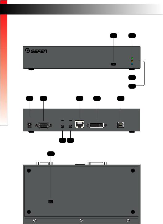
Introduction |
|
|
|
|
|
Page Title |
|
Started |
|
|
|
Sender Unit |
|
|
|
|
|
|
|
|
1 |
2 |
|
Getting |
|
|
|
|
|
||
|
|
|
|
|
|
|
|
|
® |
|
|
|
|
|
|
|
|
|
|
|
|
|
Link |
DVI KVM HDBaseT™ Extender S |
|
|
|
Video |
|||
|
|
|
Power |
||||
w/ USB, RS-232, 2-way Audio, and POH |
|
USB |
|
||||
|
|
|
|
|
|
|
4 |
|
|
|
|
|
|
|
3 |
5 |
6 |
|
|
|
9 |
10 |
11 |
EXT-DVIKA-HBT2-S |
|
|
|
|
|
|
|
Non-POH |
|
|
|
|
|
|
USB Host |
48V DC |
|
|
|
Audio |
|
|
Interface |
|
RS-232 |
|
In |
Out |
Link |
DVI-D In |
|
|
|
|
7 |
8 |
|
|
|
|
12 |
|
|
|
|
||
|
ON |
WE |
|
|
|
|
|
|
1 |
2 3 4 |
|
|
|
|
|
|
|
|
|
|
page | 2 |
|
|

Getting Started
IntroductPage Tiontle
ID
1
2
3
4
5
6
7
8
9
10
11
12
Name |
Description |
USB |
Connect the included USB TypeAto Mini- |
|
USB Type B cableto this connector. |
|
This connector provides firmware updates |
|
and control using the Syner-G software. |
Link |
This LED glows solid green when the Sender |
|
unit and Receiver unit are connected and |
|
passing video. |
Video |
This LED glows solid amber when the |
|
Sender unit and Receiver unit are connected |
|
and passing video. |
Power |
This LED glows solid blue when the unit is |
|
connected to an AC outlet and the unit is |
|
powered ON. |
Non-POH 48V DC |
Use this port only when using a HDBaseT- |
|
compatible device as the Receiver. |
RS-232 |
Connect the included RS-232 cable from this |
|
port to an RS-232 device. |
Audio In |
Connect a 3.5mm mini-stereo cable from the |
|
Line Out jack on the multimedia PC to this |
|
jack. SeeAudio Connections (page 13) |
|
for more information. |
Audio Out |
Connect a 3.5mm mini-stereo cable from this |
|
jack to the Line In jack of a multimedia PC. |
|
SeeAudio Connections (page 13) for more |
|
information. |
Link |
Connects the Sender unit to the Receiver |
|
unit using shielded CAT-5e (or better) cable. |
DVI-D In |
Connect the included DVI cable from this |
|
connector to the DVI source. |
USB Host Interface |
Connect the included USB cable from the |
|
computer to this USB port. |
DIP Switches |
Controls various features on this product. |
|
See DIP Switch Configuration (page15) |
|
for more information. |
|
|
page | 3

Getting Started
|
|
Introduction |
Receiver Unit |
|
|
|
1 |
2 |
® |
|
|
|
|
Link |
DVI KVM HDBaseT™ Extender R |
|
Video |
|
Power |
|
w/ USB, RS-232, 2-way Audio, and POH |
USB |
|
4
3
5 |
6 |
7 |
10 |
11 |
|
|
|
|
|
||||
EXT-DVIKA-HBT2-R |
|
|
|
|
|
|
|
|
|
|
|
|
|
POH |
|
|
|
Audio |
|
|
|
|
|
|
USB |
|
|
|
|
|
|
|
|
|
|
|
|
||||
|
|
|
|
|
|
|
|
|
|
|
|
|
|
48V DC |
|
|
|
|
|
|
|
|
|
|
|
|
|
|
Mic |
|
|
|
|
|
|
|
|
RS-232 |
Line |
In |
Out |
Link |
DVI-D Out |
1 |
2 |
3 |
4 |
8 |
9 |
12 |
13
|
|
|
|
|
|
|
|
|
|
|
|
|
|
|
|
|
|
|
|
|
|
|
|
|
|
|
|
ON |
1 2 |
|
|
|
|
|
|
|
|
|
|
|
|
|
|
|
|
|
|
|
|
|
|
|
|
|
|
|
|
|
|
page | 4

Getting Started
|
|
|
|
Introduction |
|
ID |
|
Name |
|
Description |
|
|
|
||||
1 |
|
USB |
|
Connect the included USB TypeAto Mini- |
|
|
|
|
|
USB Type B cableto this connector. |
|
|
|
|
|
This connector provides firmware updates |
|
|
|
|
|
and control using the Syner-G software. |
|
2 |
|
Link |
|
This LED glows solid green when the Sender |
|
|
|
|
|
unit and Receiver unit are connected and |
|
|
|
|
|
passing video. |
|
3 |
|
Video |
|
This LED glows solid amber when the |
|
|
|
|
|
Sender unit and Receiver unit are connected |
|
|
|
|
|
and passing video. |
|
4 |
|
Power |
|
This LED glows solid blue when the unit is |
|
|
|
|
|
connected to an AC outlet and the unit is |
|
|
|
|
|
powered ON. |
|
5 |
|
POH 48V DC |
|
Connect the included power supply to |
|
|
|
|
|
this power connector. The Sender unit is |
|
|
|
|
|
powered over the CAT-5e (or better) cable. |
|
6 |
|
RS-232 |
|
Connect an RS-232 cable from this port to an |
|
|
|
|
|
RS-232 device. SeeRS-232 Interface (page |
|
|
|
|
|
19) for more information. |
|
7 |
|
Mic / Line |
|
Use this switch to set the Audio In jack to |
|
|
|
|
|
accept line-level or mic-level input signals. |
|
8 |
|
Audio In |
|
Connect a 3.5mm mini-stereo cable from the |
|
|
|
|
|
Line Out jack on the multimedia PC to this |
|
|
|
|
|
jack. SeeAudio Connections (page 13) |
|
|
|
|
|
for more information. |
|
9 |
|
Audio Out |
|
Connect a 3.5mm mini-stereo cable from this |
|
|
|
|
|
jack to the Line In jack of a multimedia PC. |
|
|
|
|
|
SeeAudio Connections (page 13) for more |
|
|
|
|
|
information. |
|
10 |
|
Link |
|
Connects the Receiver unit to the Sender |
|
|
|
|
|
unit using shielded CAT-5e (or better) cable. |
|
|
|
|
|
|
|
page | 5

Getting Started
|
|
|
|
Introduction |
|
ID |
|
Name |
|
Description |
|
|
|
||||
11 |
|
DVI-D Out |
|
Connect a DVI cable from this connector to |
|
|
|
|
|
the DVI display. |
|
12 |
|
USB (1, 2, 3, 4) |
|
Connect up to four USB devices to these |
|
|
|
|
|
USB ports. |
|
13 |
|
DIP Switches |
|
Controls various features on this product. |
|
|
|
|
|
See DIP Switch Configuration (page15) |
|
|
|
|
|
for more information. |
|
|
|
|
|
|
|
page | 6

Getting Started
Installation
Connection Instructions
►► Video
1.Connect the included DVI cable from the DVI source to the DVI-D In port on the Sender unit.
2.Connect a display to the DVI-D Out port on the Receiver unit.
Tip
An HDMI cable can be connected to the output when using a Gefen DVI to
HDMI cable (Gefen part no. CAB-DVI2HDMI-LCK-06MM).
►► Link
3.Connect a shielded CAT-5e (or better) cable from the Link port on the Sender unit to the Link port on the Receiver unit.
Maximum Resolution |
Mode |
Distance |
HDMI |
Long Reach mode 495 feet (150 meters) |
|
•1920 x 1080p 60 Hz (8-bit)
DVI
•1920 x 1200 60 Hz
HDMI |
Normal mode |
330 feet (100 meters) |
•3840 x 2160p 60 Hz (4:2:0)
DVI
•1920 x 1200 60 Hz
See Long-Reach Mode (page 18) for more information.
►► Audio (see Audio Connections (page 13) for more information)
4.Connect a 3.5mm mini-stereo cable from the Audio In port on the Sender unit to the audio source.
5.Connect a pair of powered speakers (or another audio output device) to the
Audio Out port on the Receiver unit.
6.Connect a line-level or mic-level input to the Audio In port on the Receiver unit. If using a mic-level input, then set the Mic / Line switch, on the Receiver unit, to the Mic position.
page | 7

Getting Started
Installation
7.Connect a 3.5mm mini-stereo cable from the Audio Out port on the Sender unit to the audio input on the computer.
Warning
If a line-level input is being connected, DO NOT connect the cable to the “Mic In” port on the computer. Doing so may damage the sound card on the computer.
►► USB
8.Connect the included USB cable from the computer to the USB Host Interface port on the Sender unit.
9.Connect up to four USB devices to the Receiver unit.
►► Power
10. Connect the included power supply to the Receiver unit.
Automation
Control Device
Application Diagram
|
|
|
CAT-5 CABLE |
|
|
|
DVI CABLE |
|
|
|
RS-232 CABLE |
|
Source |
|
USB |
|
|
|
3.5MM AUDIO CABLE |
|
USB |
Keyboard |
Mouse |
|
Audio |
||
Audio |
|
|
|
|
|
|
|
DVI |
USB |
|
|
|
|
|
|
|
|
External Storage |
Printer |
-232 |
EXT-DVIKA-HBT2 Receiver |
|
|
EXT-DVIKA-HBT2 Sender |
|
|
|
RS |
|
|
|
|
|
DVI |
|
|
-232 |
|
Display |
|
RS |
|
|
|
Audio |
|
|
|
OR |
Audio |
|
|
|
|
Powered Speakers |
RS-232 |
Microphone |
|
|
|
|
|
|
Controlled Device |
Media player |
|
|
|
|
||
EXT-DVIKA-HBT2
page | 8
This page left intentionally blank.
Loading...