

Page 1
*Preferred
DVI KVM
HDBaseT Extender
w/ USB, RS-232, 2-way Audio, and POH
EXT-DVIKA-HBT2
User Manual
™
Release A2
Page 2

Important Safety Instructions
1. Read these instructions.
2. Keep these instructions.
3. Heed all warnings.
4. Follow all instructions.
5. Do not use this product near water.
6. Clean only with a dry cloth.
7. Do not block any ventilation openings. Install in accordance with the manufacturer’s
instructions.
8. Do not install or place this product near any heat sources such as radiators, heat
registers, stoves, or other apparatus (including ampliers) that produce heat.
9. Do not defeat the safety purpose of the polarized or grounding-type plug. A polarized
plug has two blades with one wider than the other. A grounding type plug has two
blades and a third grounding prong. The wide blade or the third prong are provided for
your safety. If the provided plug does not t into your outlet, consult an electrician for
replacement of the obsolete outlet.
10. Protect the power cord from being walked on or pinched particularly at plugs,
convenience receptacles, and the point where they exit from the apparatus.
11. Only use attachments/accessories specied by the manufacturer.
12. To reduce the risk of electric shock and/or damage to this product, never handle or
touch this unit or power cord if your hands are wet or damp. Do not expose this
product to rain or moisture.
13. Unplug this apparatus during lightning storms or when unused for long periods of time.
14. Refer all servicing to qualied service personnel. Servicing is required when the
apparatus has been damaged in any way, such as power-supply cord or plug is
damaged, liquid has been spilled or objects have fallen into the apparatus,
the apparatus has been exposed to rain or moisture, does not operate normally,
or has been dropped.
15. Batteries that may be included with this product and/or accessories should never be
exposed to open ame or excessive heat. Always dispose of used batteries
according to the instructions.
ii
Page 3

Warranty Information
Gefen warrants the equipment it manufactures to be free from defects in material and
workmanship.
If equipment fails because of such defects and Gefen is notied within two (2) years from
the date of shipment, Gefen will, at its option, repair or replace the equipment, provided
that the equipment has not been subjected to mechanical, electrical, or other abuse or
modications. Equipment that fails under conditions other than those covered will be
repaired at the current price of parts and labor in effect at the time of repair. Such repairs
are warranted for ninety (90) days from the day of reshipment to the Buyer.
This warranty is in lieu of all other warranties expressed or implied, including without
limitation, any implied warranty or merchantability or tness for any particular purpose, all of
which are expressly disclaimed.
1. Proof of sale may be required in order to claim warranty.
2. Customers outside the US are responsible for shipping charges to and from Gefen.
3. Copper cables are limited to a 30 day warranty and cables must be in their original
condition.
The information in this manual has been carefully checked and is believed to be accurate.
However, Gefen assumes no responsibility for any inaccuracies that may be contained
in this manual. In no event will Gefen be liable for direct, indirect, special, incidental, or
consequential damages resulting from any defect or omission in this manual, even if
advised of the possibility of such damages. The technical information contained herein
regarding the features and specications is subject to change without notice.
For the latest warranty coverage information, refer to the Warranty and Return Policy under
the Support section of the Gefen Web site at www.gefen.com.
iii
Page 4

Contacting Gefen Technical Support
Technical Support
(707) 283-5900 (800) 472-5555
8:00 AM to 5:00 PM Monday - Friday, Pacic Time
Email
support@gefen.com
Web
http://www.gefen.com
Mailing Address
Gefen
Core Brands, LLC
c/o Customer Service
1800 S McDowell Blvd
Petaluma, CA 94954 USA
Product Registration
Register your product here: http://www.gefen.com/kvm/Registry/Registration.jsp
iv
iv
Page 5

Operating Notes
• Always make sure that this product is running the latest rmware. The Gefen
Syner-G™ Software Suite is a free downloadable application from Gefen that provides
automatic download and installation of rmware upgrades for this product.
Download the application here: http://www.gefen.com/synerg/
• This product is only compatible with Gefen Syner-G 2.1.x and later, in order to support
EDID management and rmware updates.
DVI KVM HDBaseT™ Extender w/ USB, RS-232, and POH is a trademark of Gefen, LLC.
© 2016 Core Brands, LLC. All Rights Reserved. All trademarks are the property of their respective owners.
Gefen, LLC reserves the right to make changes in the hardware, packaging, and any accompanying documentation
without prior written notice.
Pb
This product uses UL listed or CE-compliant power supplies.
v
Page 6

Features and Packing List
Features
• Extends DVI, USB, RS-232, and 2-way Audio over a single CAT-5e
◦ 1080p Full HD (1920 x 1080 @ 60Hz, 4:4:4, 12-bit), up to 330 feet/100 meters
◦ 1080p Full HD (1920 x 1080 @ 60Hz, 4:4:4, 8-bit), up to 495 feet/150 meters
◦ WUXGA (1920 x 1200 @ 60Hz, 8-bit), up to 495 feet/150 meters
• Extends HDMI**, USB, RS-232, and 2-way Audio over a single CAT-5e
◦ 4K Ultra HD (3840 x 2160 @ 60Hz, 4:2:0, 8-bit), up to 330 feet/100 meters
◦ 4K Ultra HD (3840 x 2160 @ 30Hz, 4:4:4, 8-bit), up to 330 feet/100 meters
◦ 4K DCI-Cinema (4096 x 2160 @ 30Hz 4:4:4, 8-bit), up to 330 feet/100 meters
◦ 1080p Full HD (1920 x 1080 @ 60Hz, 4:4:4, 12-bit), up to 330 feet/100 meters
◦ 1080p Full HD (1920 x 1080 @ 60Hz, 4:4:4, 8-bit), up to 495 feet/150 meters
◦ WUXGA (1920 x 1200 @ 60Hz, 8-bit), up to 495 feet/150 meters
• HDMI Features Supported:
◦ HDMI 2.0 up to 4K 60Hz, 4:2:0, 8-bit color
◦ HDCP 2.2 and 1.4
◦ 12-bit Deep Color
◦ LPCM 7.1 audio, Dolby Atmos®, Dolby® TrueHD, DTS:X™, and DTS-HD Master
Audio™ pass-through
◦ 3DTV pass-through
◦ CEC pass-through
◦ Lip Sync pass-through
• Analog L/R Stereo Audio extension from Sender to Receiver and from Receiver to
Sender
• Receiver audio input accommodates a microphone or a line level audio source
• POH (Power Over HDBaseT™) feature provides power to Sender unit over the link
cable - only the Receiver needs external power
• Advanced EDID Management via Gefen Syner-G™ software
• Link Quality Monitoring via Gefen Syner-G™ software
• In-eld rmware update via USB, using Gefen Syner-G™ software
• Locking power connector
• 1U tall, half-rack-width enclosures can be:
◦ Surface-mounted
◦ Installed in a standard 19-inch rack using the EXT-RACK-1U-GRY rack tray
(available separately)
◦ Placed on a shelf
** Use Gefen DVI to HDMI cables
vi
Page 7

Features and Packing List
1080P
®
®
™
2.2
4K
DCI, 4096 x 2160, 30Hz
60Hz, 4:2:0
Deep Color Support
CINEMA
DCI, 4096 x 2160, 30Hz
Packing List
The DVI KVM HDBaseT™ Extender w/ USB, RS-232, and POH ships with the items listed
below. The packing contents of the Sender and Receiver unit are listed below. If any of
these items are not present in the box when you rst open it, immediately contact your
dealer or Gefen.
• 1 x DVI KVM HDBaseT™ Extender w/ USB, RS-232, and POH - Sender unit
• 1 x DVI KVM HDBaseT™ Extender w/ USB, RS-232, and POH - Receiver unit
• 1 x 6 ft. DVI cable (M-M)
• 2 x 6 ft. 3.5mm mini-stereo cable (M-M)
• 1 x 6 ft. Dual-Link DVI cable (M-M)
• 1 x 6 ft. USB A-B cable (M-M)
• 8 x Self-Adhesive Rubber Feet
• 4 x L-Shaped Surface-Mounting Brackets
• 8 x 6mm M3 Phillips at head machine screws, 0.5mm pitch, for use with
• 4 x 5mm 6-32 Phillips at head machine screws, for use with EXT-RACK-1U
• 1 x 48V/1A DC power supply with locking plug
• 1 x IEC AC power cord with interchangeable connectors (US, UK, EU, AU)
• 1 x Quick-Start Guide
EXT-MP-C01
vii
Page 8

Table of Contents
1 Getting Started
Introduction............................................................................................................ 2
Sender Unit ................................................................................................... 2
Receiver Unit ................................................................................................. 4
Installation ............................................................................................................. 7
Connection Instructions ................................................................................. 7
Application Diagram ...................................................................................... 8
2 Basic Operation
LED Status .......................................................................................................... 12
Audio Connections .............................................................................................. 13
DIP Switch Conguration .................................................................................... 15
EDID Management ...................................................................................... 16
EDID Lock ................................................................................................... 17
HDCP .......................................................................................................... 17
Long-Reach Mode ....................................................................................... 18
RS-232 Interface ................................................................................................. 19
RS-232 Interface ......................................................................................... 19
3 Advanced Operation
Using Syner-G™ ................................................................................................. 24
Verifying the USB Driver ............................................................................. 24
Downloading an EDID ................................................................................. 26
Uploading an EDID ..................................................................................... 29
Copying an EDID ........................................................................................ 31
Viewing an EDID ......................................................................................... 33
4 Appendix
Default Settings ................................................................................................... 40
Sender Unit DIP Switches ........................................................................... 40
Receiver Unit DIP Switches ........................................................................ 40
Updating the Firmware ........................................................................................ 41
Network Cable Diagram ...................................................................................... 47
Rack Tray Installation .......................................................................................... 48
Specications ...................................................................................................... 49
Index.................................................................................................................... 51
viii
Page 9

This page left intentionally blank.
Page 10

This page left intentionally blank.
Page 11

DVI KVM
HDBaseT Extender
w/ USB, RS-232, 2-way Audio, and POH
1 Getting Started
™
Page 12
DVI KVM HDBaseT Extender S
w/ USB, RS-232, 2-way Audio, and POH
Link
USB
Video
Power
®
™
DVI KVM HDBaseT Extender S
w/ USB, RS-232, 2-way Audio, and POH
Link
USB
Video
Power
®
™
EXT-DVIKA-HBT2-S
Non-POH
48V DC
RS-232
Audio
In Out Link
USB Host
Interface
DVI-D In
Introduction
Getting Started
®
DVI KVM HDBaseT Extender S
w/ USB, RS-232, 2-way Audio, and POH
5 6 9 10 11
EXT-DVIKA-HBT2-S
Non-POH
48V DC
™
RS-232
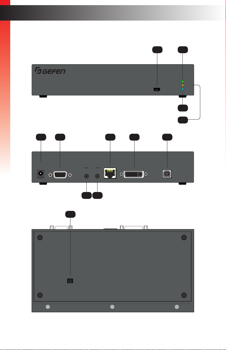
Sender Unit
Audio
In Out Link
Page Title
1 2
Link
Video
USB
Power
4
3
USB Host
Interface
DVI-D In
12
ON WE
1 2 3 4
7 8
page | 2
Page 13

ID Name Description
1 USB Connect the included USB Type A to Mini-
USB Type B cable to this connector.
This connector provides rmware updates
and control using the Syner-G software.
Getting Started
2 Link This LED glows solid green when the Sender
unit and Receiver unit are connected and
passing video.
Page Title
Introduction
3 Video This LED glows solid amber when the
4 Power This LED glows solid blue when the unit is
5 Non-POH 48V DC Use this port only when using a HDBaseT-
6 RS-232 Connect the included RS-232 cable from this
7 Audio In Connect a 3.5mm mini-stereo cable from the
8 Audio Out Connect a 3.5mm mini-stereo cable from this
9 Link Connects the Sender unit to the Receiver
10 DVI-D In Connect the included DVI cable from this
Sender unit and Receiver unit are connected
and passing video.
connected to an AC outlet and the unit is
powered ON.
compatible device as the Receiver.
port to an RS-232 device.
Line Out jack on the multimedia PC to this
jack. See Audio Connections (page 13)
for more information.
jack to the Line In jack of a multimedia PC.
See Audio Connections (page 13) for more
information.
unit using shielded CAT-5e (or better) cable.
connector to the DVI source.
11 USB Host Interface Connect the included USB cable from the
12 DIP Switches Controls various features on this product.
computer to this USB port.
See DIP Switch Conguration (page 15)
for more information.
page | 3
Page 14

Receiver Unit
DVI KVM HDBaseT Extender R
w/ USB, RS-232, 2-way Audio, and POH
Link
USB
Video
Power
®
™
DVI KVM HDBaseT Extender R
w/ USB, RS-232, 2-way Audio, and POH
Link
USB
Video
Power
®
™
USB
EXT-DVIKA-HBT2-R
POH
48V DC
RS-232 Line
Mic
In Out Link DVI-D Out
1 2 3 4
Audio
Introduction
Getting Started
®
DVI KVM HDBaseT Extender R
w/ USB, RS-232, 2-way Audio, and POH
™
5 6 7 10 11
EXT-DVIKA-HBT2-R
POH
48V DC
RS-232 Line
13
Audio
Mic
In Out Link DVI-D Out
8 9
1
USB
2
Link
Video
Power
4
3
USB
1 2 3 4
12
ON
1 2
page | 4
Page 15

ID Name Description
1 USB Connect the included USB Type A to Mini-
USB Type B cable to this connector.
This connector provides rmware updates
and control using the Syner-G software.
Getting Started
2 Link This LED glows solid green when the Sender
unit and Receiver unit are connected and
passing video.
Introduction
3 Video This LED glows solid amber when the
4 Power This LED glows solid blue when the unit is
5 POH 48V DC Connect the included power supply to
6 RS-232 Connect an RS-232 cable from this port to an
7 Mic / Line Use this switch to set the Audio In jack to
8 Audio In Connect a 3.5mm mini-stereo cable from the
9 Audio Out Connect a 3.5mm mini-stereo cable from this
Sender unit and Receiver unit are connected
and passing video.
connected to an AC outlet and the unit is
powered ON.
this power connector. The Sender unit is
powered over the CAT-5e (or better) cable.
RS-232 device. See RS-232 Interface (page
19) for more information.
accept line-level or mic-level input signals.
Line Out jack on the multimedia PC to this
jack. See Audio Connections (page 13)
for more information.
jack to the Line In jack of a multimedia PC.
See Audio Connections (page 13) for more
information.
10 Link Connects the Receiver unit to the Sender
unit using shielded CAT-5e (or better) cable.
page | 5
Page 16

ID Name Description
11 DVI-D Out Connect a DVI cable from this connector to
12 USB (1, 2, 3, 4) Connect up to four USB devices to these
Getting Started
the DVI display.
USB ports.
Introduction
13 DIP Switches Controls various features on this product.
See DIP Switch Conguration (page 15)
for more information.
page | 6
Page 17

Installation
Connection Instructions
► Video
1. Connect the included DVI cable from the DVI source to the DVI-D In port on the
Getting Started
Sender unit.
2. Connect a display to the DVI-D Out port on the Receiver unit.
► Link
3. Connect a shielded CAT-5e (or better) cable from the Link port on the Sender unit
to the Link port on the Receiver unit.
Maximum Resolution Mode Distance
HDMI
• 1920 x 1080p 60 Hz (8-bit)
DVI
• 1920 x 1200 60 Hz
Tip
An HDMI cable can be connected to the output when using a Gefen DVI to
HDMI cable (Gefen part no. CAB-DVI2HDMI-LCK-06MM).
Long Reach mode 495 feet (150 meters)
HDMI
• 3840 x 2160p 60 Hz (4:2:0)
DVI
• 1920 x 1200 60 Hz
See Long-Reach Mode (page 18) for more information.
► Audio (see Audio Connections (page 13) for more information)
4. Connect a 3.5mm mini-stereo cable from the Audio In port on the Sender unit
to the audio source.
5. Connect a pair of powered speakers (or another audio output device) to the
Audio Out port on the Receiver unit.
6. Connect a line-level or mic-level input to the Audio In port on the Receiver unit.
If using a mic-level input, then set the Mic / Line switch, on the Receiver unit,
to the Mic position.
Normal mode 330 feet (100 meters)
page | 7
Page 18

7. Connect a 3.5mm mini-stereo cable from the Audio Out port on the Sender unit to
the audio input on the computer.
Getting Started
Warning
If a line-level input is being connected, DO NOT connect the cable to the
“Mic In” port on the computer. Doing so may damage the sound card on the
computer.
► USB
8. Connect the included USB cable from the computer to the USB Host Interface
port on the Sender unit.
9. Connect up to four USB devices to the Receiver unit.
► Power
10. Connect the included power supply to the Receiver unit.
Installation
Automation
Control Device
RS-232
Controlled Device
Application Diagram
USB
Audio
Audio
DVI
RS-232
EXT-DVIKA-HBT2 Sender
RS-232
Microphone
page | 8
Audio
USB
DVI Source
EXT-DVIKA-HBT2 Receiver
DVI
Audio
OR
Media player
3.5MM AUDIO CABLE
MouseKeyboard
PrinterExternal Storage
CAT-5 CABLE
DVI CABLE
RS-232 CABLE
USB
DVI Display
Powered Speakers
EXT-DVIKA-HBT2
Page 19

This page left intentionally blank.
Page 20

This page left intentionally blank.
Page 21

DVI KVM
HDBaseT Extender
w/ USB, RS-232, 2-way Audio, and POH
2 Basic Operation
™
Page 22

LED Status
The Link, Video, and Power LED indicators provides basic information on the current
status of the this product.
The information, in the table below, applies to both the Sender and Receiver unit.
Basic OperationBasic Operation
LED Status Description
Link Solid green • The Sender / Receiver unit is powered.
• Link integrity between Sender and Receiver unit
is good.
Video Solid amber • HDCP content is detected
Flashing amber • Non-HDCP content is detected.
Power Solid blue
• The Sender / Receiver unit is powered.
page | 12
Page 23

DVI KVM HDBaseT Extender S
w/ USB, RS-232, 2-way Audio, and POH
Link
USB
Video
Power
®
™
Audio Connections
DVI KVM HDBaseT Extender R
w/ USB, RS-232, 2-way Audio, and POH
Link
USB
Video
Power
®
™
The DVI KVM HDBaseT™ Extender can accept either Mic or Line-level inputs on the
Receiver unit. Use the Mic / Line switch to set the proper input level.
1. Locate the Mic / Line switch, next to the Audio In port, and set the switch to the
desired audio input type. If connecting a microphone, then set the Mic / Line switch
Basic Operation
to the Mic position. Otherwise, set the switch to the Line position.
2. Connect the 3.5mm mini-stereo jack from the audio source to the Audio In port
on the Receiver unit.
Mic / Line switch
Receiver unit
EXT-DVIKA-HBT2-R
POH
48V DC
RS-232 Line
Audio
Mic
In Out Link DVI-D Out
Connect to audio source
1 2 3 4
3. In order to get the audio from the Receiver unit to the computer, connect a 3.5mm
mini-stereo cable from the Audio Out port on the Sender unit to the Line In jack
on the computer.
Warning
If you are using a line-level input, DO NOT connect the cable to the “Mic In”
port on the computer; doing so will result in audio “clipping” and may cause
damage to the computer’s sound card.
Sender unit
EXT-DVIKA-HBT2-S
Non-POH
48V DC
RS-232
Audio
In Out Link
Connect to Line Out
on computer
DVI-D In
Connect to Line In
on computer
USB Host
Interface
USB
page | 13
Page 24

Audio Connections
DVI KVM HDBaseT Extender R
w/ USB, RS-232, 2-way Audio, and POH
Link
USB
Video
Power
®
™
4. Connect another 3.5mm-to-3.5mm mini-stereo cable between the Audio Out jack on
the computer and the Audio In jack on the Sender unit. Note that any audio device
(e.g. MP3 player, etc.) can be connected to the Line In jack on the Sender unit.
5. Finally, we’ll connect a set of powered computer speakers to the Audio Out jack
Basic Operation
on the Receiver unit.
Connect to computer
speakers
EXT-DVIKA-HBT2-R
POH
48V DC
RS-232 Line
Audio
Mic
In Out Link DVI-D Out
USB
1 2 3 4
In the diagram below, the USB devices have been removed from the Sender and
Receiver unit, for purposes of clarity. Arrowheads indicate the audio signal path.
Figure 2.1 - Speaker and audio connections
OR
Microphone
Audio source
(line-level)
Audio In
Powered speakers
Audio Out
Receiver unit
CAT-5e
(or better)
cable
Sender unit
page | 14
Audio In
Audio Out
Computer
Page 25

DIP Switch Conguration
DVI KVM HDBaseT Extender S
w/ USB, RS-232, 2-way Audio, and POH
Link
USB
Video
Power
®
™
EXT-DVIKA-HBT2-S
Non-POH
48V DC
RS-232
Audio
In Out Link
USB Host
Interface
DVI-D In
DVI KVM HDBaseT Extender R
w/ USB, RS-232, 2-way Audio, and POH
Link
USB
Video
Power
®
™
USB
EXT-DVIKA-HBT2-R
POH
48V DC
RS-232 Line
Mic
In Out Link DVI-D Out
1 2 3 4
Audio
On the bottom of both the Sender and Receiver unit are a bank of DIP switches.
The Sender unit has 4 DIP switches and the Receiver unit has two.
Remove the gray tape on the bottom of the unit to expose the DIP switches.
Basic Operation
ON WE
1 2 3 4
Sender unit
ON WE
1 2 3 4
DIP switches
Receiver unit
ON
1 2
DIP switches
ON
page | 15
1 2
Page 26

DIP Switch Conguration
EDID Management
Each of the following sections describe the DIP switch settings that control each feature.
DIP switches that are not related to a specic feature have been grayed-out. Note that DIP
switch settings can be used independently or in conjunction with other features, as desired.
Basic Operation
Information
DIP switch 2, on the Receiver unit, is not used and is reserved for optional
future expansion.
This product provides EDID management. The Sender unit can use the EDID from the sink
device (downstream EDID) or the built-in default EDID.
Description Sender unit Receiver unit
Local EDID mode (default)
• Copies the downstream EDID locally in
HDBT mode.
ON WE
ON
• Modies downstream EDID to support only
up to 1080p60 8-bit in Long Reach mode.
Pass-Through EDID mode
• Allows all video and audio features of the
connected device to be passed to the
source device.
page | 16
1 2 3 4
ON WE
1 2 3 4
1 2
ON
1 2
Page 27

DIP Switch Conguration
EDID Lock
The EDID lock feature prevents the currently stored EDID from being overwritten.
Description Sender unit Receiver unit
Basic Operation
EDID Unlock (default)
• The existing EDID is replaced with another
EDID when the unit is powered. The EDID
can be from a downstream sink, a local
EDID, or an EDID that is uploaded using
the Syner-G™ software.
ON SAB
1 2 3 4
ON
1 2
EDID Lock
• Locks the current EDID and prevents it
from being overwritten.
ON SAB
1 2 3 4
ON
1 2
HDCP
This feature allows HDCP content to either be passed-through or disabled on the input.
Disabling this feature does not decrypt HDCP content.
Description Sender unit Receiver unit
HDCP Enable (default)
• Allows HDCP content to pass-through from
the source.
HDCP Disable
• Disables HDCP content from being
passed-through from the source.
ON SAB
1 2 3 4
ON SAB
1 2 3 4
ON
1 2
ON
1 2
page | 17
Page 28

DIP Switch Conguration
Long-Reach Mode
When set to long reach mode, resolutions up to 1920 x 1200 @ 60 Hz can be extended
up to 495 feet (150 meters).
Basic Operation
Description Sender unit Receiver unit
HDBT mode (default)
• HDMI: Allows resolutions up to 3840 x
2160p 60 Hz @ 4:2:0 to be extended up to
330 feet (100 meters).
• DVI: Allows resolutions up to 1920 x 1200
60 Hz to be extended up to 330 feet (100
meters).
Long-reach mode
• DVI: Allows resolutions up to 1920 x 1200
60 Hz, to be extended to a maximum
distance of 495 feet (150 meters).
ON SAB
1 2 3 4
ON SAB
1 2 3 4
ON
1 2
ON
1 2
page | 18
Page 29

RS-232 Interface
DE-9
Basic Operation
Automation Device Extender
RS-232 Interface
564738291
DCD
RXD
TXD
DTR
GND
DSR
RTS
CTS
R1
1
2
3
4
5
6
7
8
9
1
2
3
4
5
6
7
8
9
Only TXD, RXD, and GND pins are used.
DCD
RXD
TXD
DTR
GND
DSR
RTS
CTS
R1
page | 19
Page 30

HDMI Out
RS-232 Interface
This product supports RS-232 pass-through, allowing the control of remote RS-232
devices.
In the example below, an RS-232 device has been connected to the Receiver unit.
Connect the automation control device to the Sender unit.
Basic Operation
Figure 2.1 - Basic RS-232 connection
Receiver unit
RS-232 device
RS-232 cable
Sender unit
Automation
Control Device
HDMI In
page | 20
Page 31

This page left intentionally blank.
Page 32

This page left intentionally blank.
Page 33

DVI KVM
HDBaseT Extender
w/ USB, RS-232, 2-way Audio, and POH
3 Advanced Operation
™
page | 23
Page 34

Using Syner-G™
Verifying the USB Driver
In order to use this product with the Gefen Syner-G™ software, a USB driver must
be installed on the computer that is running the Syner-G™ software. This driver is
automatically installed when the Syner-G™ Software Suite is installed.
1. Download and install the Gefen Syner-G™ Software Suite. The Syner-G™ software
Advanced Operation
can be downloaded here: http://www.gefen.com/synerg/
2. Connect a mini-USB-to-USB cable (not included) from the USB port on the front of the
Sender or Receiver unit to an available USB port on the computer.
3. From the Windows Desktop, click the Start button, select Computer, then right-click
and select Manage from the context menu.
page | 24
Page 35

4. The Computer Management window will open.
5. In the left window pane, under System Tools, click Device Manager.
6. In the right window pane, locate Ports (COM & LPT).
The device driver will be displayed. In this case, EXT-DVIKA-HBT2-S will be
displayed. If the USB cable is connected to the Receiver unit, then the device driver
Advanced Operation
will be EXT-DVIKA-HBT2-R.
Using Syner-G™
USB driver
page | 25
Page 36

Using Syner-G™
Downloading an EDID
EDID data can be downloaded from the connected Gefen Detective device to a local le.
Note that the Downstream EDID or Bank EDID data cannot be downloaded to a le.
To download this EDID data, it must rst be copied to the Local EDID. See Copying an
EDID (page 31) for more information on copying EDID data.
Advanced Operation
1. Click the Manage a Product button and select the connected product from the
drop-down list.
2. Click the Manage EDID tab.
page | 26
Page 37

Using Syner-G™
3. Information about the currently selected device will be displayed in the Version Info
eld.
Advanced Operation
4. Click the drop-down list next to the Download button, and select the desired EDID.
In this example, we will select Extender: Local EDID.
Version Info eld
5. Click the Save As button.
6. The Windows Save File dialog will be displayed. Select the desired folder and specify
the name of the le in the File name eld, within the Save File dialog. Make sure to
specify the .bin extension to the lename.
page | 27
Page 38

Advanced Operation
7. Click the Save button.
EDID le name
Using Syner-G™
Save button
page | 28
Page 39

Using Syner-G™
Uploading an EDID
1. Click the Manage a Product button and select the connected product from the
drop-down list.
2. Click the Manage EDID tab.
Advanced Operation
3. Click the Upload EDID to drop-down list to select the location where the EDID will be
uploaded. The EDID can be uploaded to the Local EDID or an EDID bank.
In the example below, we will select Local EDID.
4. Click the Browse button.
page | 29
Page 40

5. The Windows Select File dialog will be displayed.
6. Select the desired EDID le. The EDID le must be in .bin format.
7. Click the Open button.
Advanced Operation
Using Syner-G™
8. Click the Upload button.
9. In the lower-left corner of the interface, the “Uploading...” message will appear as the
EDID is uploaded. Once the operation is complete, the “Upload Complete.” message
will be displayed.
page | 30
Page 41

Using Syner-G™
Copying an EDID
1. Click the Manage a Product button and select the connected product from the
drop-down list.
2. Click the Manage EDID tab.
Advanced Operation
3. Click the Copy EDID from drop-down list to select the location from where the EDID
will be copied. The EDID can be copied from any of the following locations:
The downstream EDID, an EDID bank, or a default EDID location
In the example below, we will select Down Stream.
4. Click the Copy EDID to drop-down list to select the location to where the EDID
will be copied. The EDID can by copied to the Local EDID or to an EDID bank.
page | 31
Page 42

Using Syner-G™
5. Click the Copy button.
Advanced Operation
6. In the lower-left corner of the interface, the “Copying...” message will appear as the
EDID is uploaded. The copy-result message will vary, depending upon the copy
operation.
In this example, since we copied the downstream EDID to the local EDID, the “Copy
result: Downstream stored to local.” message is displayed.
page | 32
Page 43

Viewing an EDID
1. Click the Manage a Product button and select the connected product from
the drop-down list.
2. Click the Manage EDID tab.
Advanced Operation
3. Click the Select EDID From Device / Display drop-down list to select the desired
EDID.
Note that the display, which is connected to the computer, is also available in the
drop-down list. In this way, we can download, view, and/or edit the EDID from the
display (sink) device.
Using Syner-G™
4. Click the View button.
page | 33
Page 44

4. After a few seconds, Syner-G will also switch to the EDID Editor screen.
See the Gefen Syner-G™ User Manual for more information on using the EDID Editor.
5. Click the desired EDID tab to view specied information on the EDID. Note that
some sections within a tab use scroll bars to indicate that more information is
available.
Advanced Operation
EDID tabs
Using Syner-G™
page | 34
Page 45

Using Syner-G™
7. Click the Details button.
Advanced Operation
8. The EDID Summary window will be displayed. Use the horizontal and vertical scroll
bar, as needed, to view the EDID information.
Scroll bar
Details button
Scroll bar
page | 35
page | 35
Page 46

9. Click the button, in the upper-right corner of the EDID Summary window to
separate the EDID Summary window from the main Syner-G window:
Advanced Operation
“X” button
“separate” button
Using Syner-G™
10. Double-click the window title bar of the detached EDID Summary to reattach it to the
main window. it to the main Syner-G window.
11. To close the EDID Summary window, either click the button, in the upper-right
corner of the EDID Summary window or click the Details button in the main
Syner-G window.
page | 36
Page 47

This page left intentionally blank.
Page 48

This page left intentionally blank.
Page 49

DVI KVM
HDBaseT Extender
w/ USB, RS-232, 2-way Audio, and POH
4 Appendix
™
page | 39
Page 50

Default Settings
Sender Unit DIP Switches
DIP swtich Function Default setting (OFF position)
Appendix
1 EDID mode Local EDID
2 EDID lock Disabled
3 HDCP Pass-through
4 Long-Reach mode HDBT mode
Receiver Unit DIP Switches
DIP swtich Funciton Default setting (OFF position)
1 Long-Reach mode HDBT mode
2 N/A ---
page | 40
Page 51

Updating the Firmware
The Syner-G™ Software Suite provides an easy way to perform rmware updates.
Before launching Syner-G™, makre sure that a USB cable is connected between the
product and the computer that is running the Syner-G™ software. Refer to the Syner-G™
Software Suite User Manual for more information on using other features with this product.
Appendix
1. Launch the Syner-G™ Software Suite from the Start Menu or using the shortcut from
the Windows Desktop.
2. Click the Manage a Product button.
page | 41
Page 52

3. Select the product from the Select your product drop-down list.
Appendix
If the product is not detected by Syner-G™, then the product will not be listed in bold
type, within the Select your product drop-down list. Verify the following:
Updating the Firmware
► The product is powered and connected to the computer that is running the
Syner-G™ Software Suite, using a USB-to-Mini USB cable.
► Make sure that the USB driver is installed and functioning correctly under
Control Panel. See Verifying the USB Driver (page 24) for more information.
page | 42
Page 53

4. Click the Update tab.
Appendix
Updating the Firmware
page | 43
Page 54

5. Click the Start button to begin downloading the rmware.
Appendix
The Syner-G™ Software Suite will automatically download the rmware le for the
selected product. This process should take a few seconds.
Once the download process has completed, the progress bar will indicate 100%,
as shown on the next page.
Updating the Firmware
page | 44
Page 55

A message will also appear at the bottom of the window, indicating that the rmware
le was successfully downloaded.
Appendix
6. Click the Install button to begin installing the software.
Updating the Firmware
Progress bar
7. The installation process will begin and the progress bar will indicate the current status.
page | 45
Page 56

Updating the Firmware
8. After the rmware update process has completed, the following message will be
displayed.
Appendix
9. Click the OK button to dismiss the message box.
10. The procedure is now complete.
page | 46
Page 57

Network Cable Diagram
Appendix
1 2 3 4 5 6 7 8
Front of RJ-45 Connector
Gefen recommends the TIA/EIA-568-B wiring option. Use the table below when
eld-terminating cable for use with Gefen products.
Pin Color Description
1 Orange / White TD+ (Transmit Data, positive differential signal)
2 Orange TD- (Transmit Data, negative differential signal)
3 Green / White RD+ (Receive Data, positive differential signal)
4 Blue Unused
5 Blue / White Unused
6 Green RD- (Receive Data, negative differential signal)
7 Brown / White Unused
8 Brown / White Unused
Information
Shielded CAT-5e (or better) cabling is recommended.
page | 47
Page 58

Rack Tray Installation
The following illustrations provide instructions for installing the Sender and/or Receiver
unit(s) in the Gefen 1U Rack Tray (Gefen part no. EXT-RACK-1U).
Appendix
Step 1 Step 2
Step 3
Step 5 Step 6
Turn unit upside down. Remove rubber feet.
Line up holes on unit and rack tray. Install countersink screws .
Ensure the unit is installed securely. Unit has been installed into rack tray.
Step 4
page | 48
Page 59

Specications
Supported Formats
Resolutions (max.) • HDMI
Appendix
Connectors, Controls, and Indicators
DVI In (Sender) • 1 x DVI, 29-pin female, digital only
DVI Out (Receiver) • 1 x DVI, 29-pin female, digital only
RS-232 (Sender) • 1 x DB-9, female
RS-232 (Receiver) • 1 x DB-9, male
Link (Sender / Receiver) • 1 x RJ-45, shielded
Audio In (Sender / Receiver) • 1 x 3.5mm mini-stereo
Audio Out (Sender / Receiver) • 1 x 3.5mm mini-stereo
Non-POH 48V DC (Sender) • 1 x 48 V DC power connector
POH 48V DC (Receiver) • 1 x 48 V DC power connector
USB Host Interface (Sender) • 1 x USB Type B, female
USB Device Connectors (Receiver) • 4 x USB Type A, female
USB (Sender / Receiver) • 1 x Mini-B type (for Gefen Syner-G)
DIP switches (Sender) • 4 x piano type
DIP switches (Receiver) • 2 x piano type
Link Indicator (Sender / Receiver) • 1 x LED, green
Video Indicator (Sender / Receiver) • 1 x LED, amber
Power Indicator (Sender / Receiver) • 1 x LED, blue
Operational
Maximum pixel clock • 165 MHz
Power input • 48 V DC
Power consumption
(Sender / Receiver, combined)
Audio: Sender to Receiver (Line)
Maximum input voltage
THD
SNR
Frequency response
3840 x 2160p 60 Hz (4:2:0)
• DVI
1920 x 1200 (WUXGA)
• 13 W
• 2 Vrms
• < 0.01 %
• >= 90 dB (20 Hz - 20 kHz)
• 20 Hz - 20 kHz +/- 0.5 dB
page | 49
Page 60

Operational
Audio: Receiver to Sender (Line)
Maximum input voltage
Appendix
THD
SNR
Frequency response
Audio: Receiver to Sender (Mic)
Maximum input voltage
THD
SNR
Frequency response
Operating temperature • +32 to +122 °F (0 to +50 °C)
Operating humidity • 5% to 90% RH, non-condensing
Storage temperature • -4 to +185 °F (-20 to +85 °C)
Storage humidity • 0% to 95% RH, non-condensing
MTBF • 50000 hours
Physical
Dimensions (W x H x D)
(not including connectors and feet)
Unit weight (Sender/Receiver) • 1.1 lbs (0.47 kg) each
• 2 Vrms
• < 0.02 % @ 10 kΩ; 1% @ 32 Ω
• >= 85 dB (20 Hz - 20 kHz)
• 20 Hz - 20 kHz +/- 0.5 dB
• 0.2 Vrms
• < 0.1 %
• >= 85 dB (20 Hz - 20 kHz)
• 20 Hz - 20 kHz +/- 0.5 dB
• 8.4” x 1.7” x 4.3” (214mm x 43mm x
110mm)
Specications
page | 50
Page 61

Index
A
Application Diagram 8
Appendix
C
Connection Instructions 7
D
Default Settings
receiver 40
sender unit 40
DIP Swtich Conguration
EDID lock 17
EDID management 16
HDCP 17
Long-Reach Mode 18
E
EDID
copying 31
downloading 26
lock 17
management 16
uploading 29
viewing 33
F
Features vi
Firmware
updating 41
N
Network Cable Diagram 47
O
Operating Notes v
P
Packing List vi
R
Rack Tray Installation 48
Receiver Unit 4
S
Safety Instructions ii
Sender Unit 2
Specications 49
Syner-G
copying an EDID 31
downloading an EDID 26
updating the rmware 41
uploading an EDID 29
using 24
viewing an EDID 33
T
Table of Contents vii
Technical Support iv
H
HDCP
control 17
L
LED Status 12
Long-Reach Mode 18
U
Updating the Firmware 41
USB Driver
verifying 24
W
Warranty Information iii
page | 51
Page 62

Stretch it. Switch it. Split it. Gefen’s got it. ®
*Preferred
20600 Nordhoff St., Chatsworth CA 91311
1800 S McDowell Blvd. Petaluma CA 94954
1-800-545-6900 818-772-9100 fax: 818-772-9120
(707) 283-5900 (800) 472-5555
www.gefen.com support@gefen.com
 Loading...