

Page 1
®
DVI RS232
ELR Extender
EXT-DVI-CAT5-ELR
User Manual
www.gefen.com
Page 2

Page 3

ASKING FOR ASSISTANCE
Rev A12
Technical Support:
Telephone (818) 772-9100
(800) 545-6900
Fax (818) 772-9120
Technical Support Hours:
8:00 AM to 5:00 PM Monday thru Friday.
Write To:
Gefen, LLC
c/o Customer Service
20600 Nordhoff St
Chatsworth, CA 91311
www.gefen.com
support@gefen.com
Notice
Gefen, LLC reserves the right to make changes in the hardware, packaging, and
any accompanying documentation without prior written notice.
DVI RS232 ELR Extender is a trademark of Gefen LLC
© 2014 Gefen, LLC. All rights reserved.
All trademarks are the property of their respective owners.
Page 4

CONTENTS
1 Introduction
2 Operation Notes
3 Features
4 Sender Unit Layout
5 Sender Unit Descriptions
6 Receiver Unit Layout
7 Receiver Unit Descriptions
8 Connecting the DVI RS232 ELR Extender
9 DIP Switches
10 DIP Switch Conguration
13 Network Cable Wiring Diagram
14 Firmware Update
15 Specications
16 Warranty
Page 5

1
Congratulations on your purchase of the DVI RS232 ELR Extender. Your
complete satisfaction is very important to us.
Gefen
Gefen delivers innovative, progressive computer and electronics add-on solutions
that harness integration, extension, distribution and conversion technologies.
Gefen’s reliable, plug-and-play products supplement cross-platform computer
systems, professional audio/video environments and HDTV systems of all sizes
with hard-working solutions that are easy to install and simple to operate.
The Gefen DVI RS232 ELR Extender
The DVI RS232 ELR Extender extends any DVI source to a monitor, touch
screen display, or other digital signage device placed at a distance up to 330 feet
(100 meters) using one CAT-5e cable. This product also extends Ethernet and
RS-232 using the same CAT-5e cable, allowing access and control of devices
using RS-232.
How It Works
Place the Sender unit next to the DVI input source. Use the included DVI cable to
connect the source to the Sender unit. Connect the Receiver unit to the monitor or
digital signage display with a DVI cable (not supplied). Use one CAT-5e cable, up
to 330 feet (100 meters), to connect the Sender unit to the Receiver unit. Connect
an RS-232 serial cable from the RS-232 port on the Sender unit to the RS-232
control device. Use another RS-232 cable to connect the RS-232 port on the
Receiver unit to the RS-232 device. Connect the Ethernet ports on both the
Sender unit and the Receiver unit to any computer source and extended Ethernet
device.
INTRODUCTION
Page 6

2
OPERATION NOTES
PLEASE READ THESE NOTES BEFORE INSTALLING OR
OPERATING THE DVI RS232 ELR EXTENDER
• CAT-5e or CAT-6a cables should not exceed 330 feet (100 meters).
• Shielded (STP) CAT-5e or CAT-6a is recommended. However, un-shielded
(UTP) CAT-5 or CAT-6 is acceptable.
NOTE: The shielded cable has an advantage by providing immunity to
Electromagnetic Interference (EMI), cell phones and A/C motors.
• The DVI RS232 ELR Extender features the ability to generate compatible
EDID and Hot Plug signals when working with different brands of source
devices and monitors.
• This product does not support HDCP content with DVI.
Page 7

3
FEATURES
Features
• Extends any DVI, RS-232, and Ethernet devices up to 330 feet
• Supports resolutions up to 1080p, 2K, and 1920x1200
• Excellent for digital signage applications
• Maximum Ethernet throughput of 100 Mbps, Full Duplex mode.
• Uses one CAT-5e cable for DDC and control signals.
• All-digital signal transmission for zero signal loss.
• Locking power connectors.
• Low power consumption (Green Mode) when DVI source is not detected.
• Field-upgradable via RS-232.
• Metal enclosure improves RF shielding.
Package Includes
(1) Gefen DVI RS232 ELR Extender - Sender unit
(1) Gefen DVI RS232 ELR Extender - Receiver unit
(1) 6 ft. DVI Cable (M - M)
(2) 5V DC Locking Power Supplies
(1) Quick-Start Guide
Page 8
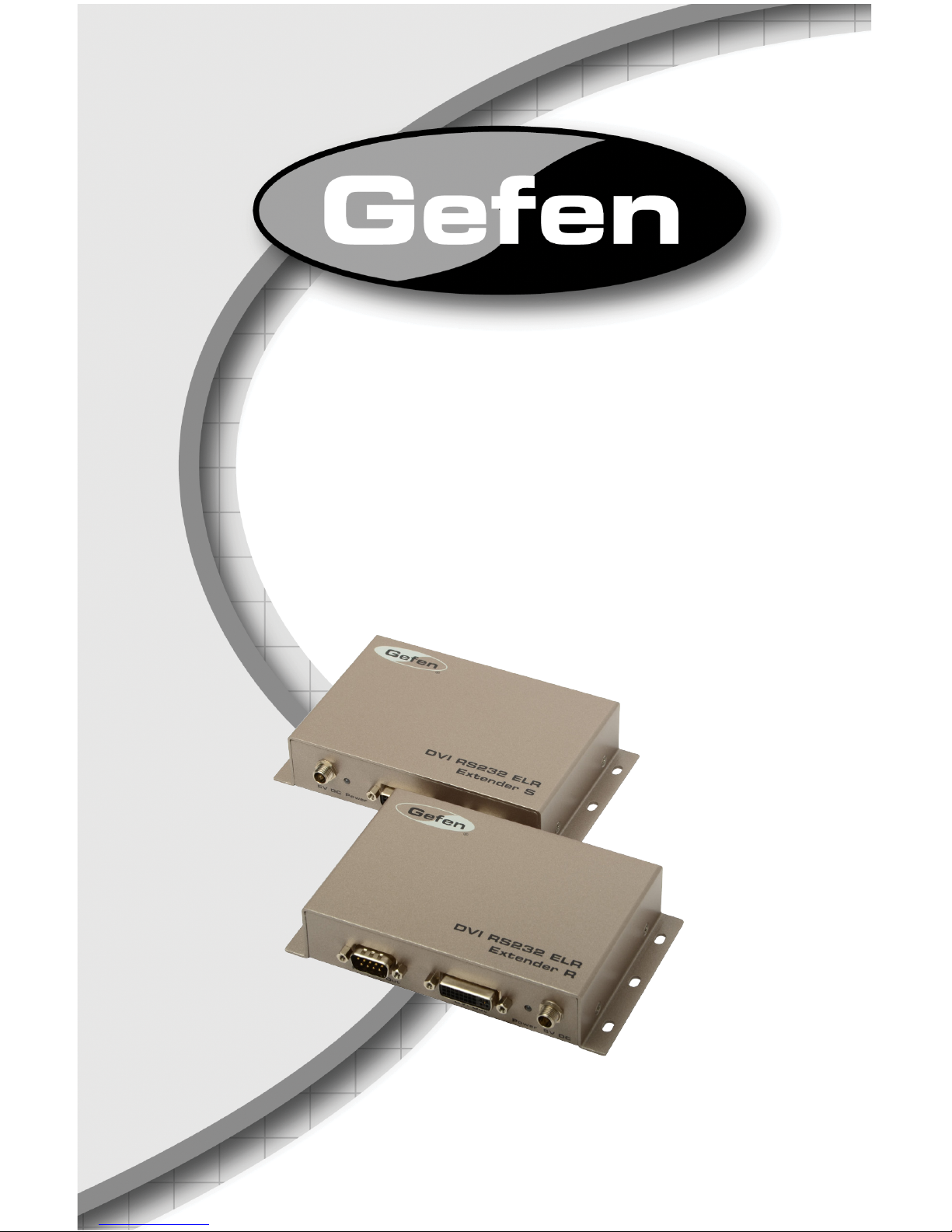
4
SENDER UNIT LAYOUT
Back
Front
1
2 3 4
5
6
Page 9

5
SENDER UNIT DESCRIPTIONS
1 5V DC Locking Power Connector
Connect the included 5V DC locking power supply to this connector.
2 Power Indicator
This two-color LED lights up red when there is no DVI source, and lights up
green when a DVI source is present
3 Locking DVI Input Port
Connect a DVI source to this port.
4 RS-232 Input Port
Connect the RS-232 host device to this port.
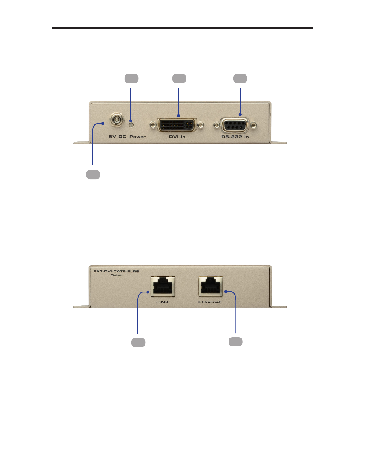
5 Link Output Jack
Connects the Sender Unit to the Receiver Unit using a CAT-5 cable.
6 Ethernet Input Jack
Connects the Sender Unit to the network using an Ethernet cable.
Page 10

6
RECEIVER UNIT LAYOUT
Back
Front
1 2 43
5
6
Page 11

7
RECEIVER UNIT DESCRIPTIONS
1 RS-232 Output Port
Connect the RS-232 device being controlled to this port.
2 Locking DVI Output Port
Connect a display to this DVI port.
3 5 V DC Locking Power Connector
Connect the included 5V DC locking power supply to this connector.
4 Power Indicator
This LED will turn bright red once the included 5V DC locking power supply has
been properly connected to the unit and the locking power supply has been
connected to an available electrical outlet. The LED will glow bright green when
a DVI source is detected.
5 Ethernet Output Jack
Connects the Receiver Unit to the network device.
6 Link Input Jack
Connects the Sender Unit to the Receiver Unit using CAT-5 cabling.
Page 12

8
CONNECTING
THE DVI RS232 ELR EXTENDER
How to Connect the DVI RS232 ELR Extender
1. Connect the DVI source to the Sender unit using the provided DVI cable.
Connect the DVI monitor to the Receiver unit using another DVI cable.
2. Connect an Ethernet cable from the device/router to the Ethernet input port
on the Sender unit with a CAT-5e or CAT-6a cable.
3. Connect the Ethernet output port on the Receiver unit to the remote device/
router with a CAT-5e or CAT-6a cable.
4. Connect a CAT-5e or CAT-6a cable between the Link port on the Sender unit
and the Link port on the Receiver unit.
NOTE: If terminating network cables in the eld, please adhere to the TIA/
EIA568B specication (please see page 13).
5. Connect the 5V DC locking power supplies to the Sender unit and Receiver
unit. Do not overtighten the locking connectors. Plug the two (2) power
supplies into an available electrical outlet.
Wiring Diagram for the DVI RS232 ELR Extender
EXT-DVI-CAT5-ELR
CAT5 CABLE
Sender
DVI Source
Router
Receiver
Touchscreen Display
DVI CABLE
RS-232 CABLE
WARNING: This product should always be connected to a
grounded electrical socket.
Page 13

9
DIP SWITCHES
DIP Switch Location
On the bottom of the DVI RS232 ELR Extender Receiver unit there are four (4)
DIP switches. The Sender unit has two DIP switches.
The DIP switches allow advanced EDID management of the DVI RS232 ELR
Extender which may be necessary when using different brands of hardware. The
DIP switches allow control over the EDID, HPD (Hot Plug Detect), and RS-232
modes.
Default settings for Receiver DIP switches
DIP Switch Position
1 OFF
2 OFF
3 ON
4 OFF
Receiver Unit DIP Switches
Sender Unit DIP Switches
Default settings for Sender DIP switches
DIP Switch Position
1 ON
2 OFF
Page 14

10
DIP SWITCH CONFIGURATION
Sender Unit
DIP 1 - ON
ON (default) - Disable
• Power is always on.
OFF - Enable
• Power is enabled only if the DVI source is connected and active. If the DVI
source enters standby mode then both the Sender Unit and Receiver Unit
will enter Green Mode. In Green Mode, both the Sender and Receiver Unit
will each consume less than 1 W of power.
DIP 2 - OFF
ON - Enable Field Upgrade Mode
• Allows the rmware to be upgraded on the Sender Unit. Both DIP switches
(1 and 2) on the Sender unit must be set to the ON position to perform a
rmware upgrade. If DIP switch 2 is in the ON position, RS-232 cannot be
extended.
OFF (default) - RS-232 Pass-through
• Use when extending RS-232 between the Sender Unit and the Receiver
Unit. DIP switch 4 must be set to the OFF position for normal operation of
the DVI RS232 Extender over CAT5 with Ethernet.
Page 15

11
DIP SWITCH CONFIGURATION
Receiver Unit
DIP 1 - OFF
ON - External EDID Mode
• DDC and HPD are passed through. Both the connection status and the full
video capabilities of the monitor. The HPD status will also be detected by
the source device.
OFF (default) - Internal EDID Mode
• Local EDID is used instead of the EDID from the display device. EDID
features newer than HDMI 1.3 are removed when the display is read. This
provides a general EDID which is compatible with more displays.
DIP 2* - OFF
ON - HPD Pass-Through
• HPD follows upstream HPD towards the source. The HPD signal will reect
the connection status between the display device and the source device. If
the source or monitor is temporarily disconnected then reconnected, there
will be a delay of 20 - 30 seconds before the content is restored to the
monitor.
OFF (default) - HPD Always High
• The HPD signal remains high regardless of the downstream HPD state. If
the source or monitor does not properly handle HPD (no picture after connecting / reconnecting source or display), set this DIP switch to the OFF
position.
*DIP switch is only functional when DIP switch 1 is set to OFF.
Page 16

12
DIP SWITCH CONFIGURATION
Receiver Unit
DIP 3* - ON
ON (default)
• If a DVI connection is used, set DIP 3 to the ON position. DVI is supported
by disabling HDCP pass-through.
OFF
• If HDMI is connected, set DIP 3 in the OFF position.
*DIP switch is only functional when DIP switch 1 is set to OFF.
DIP 4 - ON
OFF - Enable Green Mode
• When DIP switch 1 is set to the OFF position, the Receiver unit is powered
only when 5V is present on the HDMI / DVI cable. Automatic Power Mode
consumes less than 1 Watt of power.
ON - Disable Green Mode
• If DIP switch 1 is set to the ON position, then the Receiver unit is placed in
Power Always Mode. In this mode, the Receiver unit is always powered.
IMPORTANT: The Green Mode feature on the Receiver unit is
not implemented on hardware versions prior to 9502. Check the
hardware version, printed on the bottom of the Receiver unit. For
example, the sample image below indicates hardware version
9401 which does not have the Green Mode feature.
Page 17

13
NETWORK CABLE WIRING DIAGRAM
1 2 3 4 5 6 7 8
Gefen recommends the TIA/EIA-568-B wiring option. Please adhere to the table
below when eld terminating cable for use with Gefen products.
Pin Color
1 Orange / White
2 Orange
3 Green / White
4 Blue
5 Blue / White
6 Green
7 Brown / White
8 Brown
CAT-5, CAT-5e, and CAT-6a cabling comes in stranded and solid core types.
Gefen recommends using solid core cabling. CAT-6 cable is also recommended.
It is recommended to use one continuous run from one end to the other. In some
cases, connecting through a patch might not work.
Page 18

14
FIRMWARE UPDATE
Updating the Firmware
1. Connect an RS-232 cable from the computer to the Sender Unit.
2. Set all DIP switches on the Sender unit to the ON position.
3. Connect the 5V DC locking power supply to the Sender Unit.
4. Go to the directory where the rmware les are stored.
5. Double-click the .BAT le. A screen similar to the following will appear:
Found sink on port 4
Autodetect platform: full sink
Autodetect platform: spi.
Autodetect size: 128k
Erasing Eeprom....Done.
progress: 100%
Total bytes: 38804. Total time: 99.906000 seconds
Burn succeeded.
Verifying le...
progress: 100%
Total bytes: 38804. Total time: 88.266000 seconds
Verication succeeded!!!
6. Return DIP switch 2 on the Sender unit to the OFF position.
7. To update the rmware on the Receiver unit, set all DIP switches on the
Receiver unit to the ON position.
8. Connect the 5V DC locking power supply to the Receiver unit.
9. Repeat steps 4 and 5.
10. The rmware update process is complete.
STOP: Before beginning the update process, disconnect the
Sender unit from the Receiver unit.
Page 19

15
Maximum Pixel Clock ...............................................................................165 MHz
Input Video Signal .................................................................................... 1.2V p-p
Input Sync Signal ............................................................................... 5V p-p (TTL)
Video Input Connector (Sender): ..................(1) DVI-I 29-pin, female (digital only)
Video Input Connector (Receiver):.................(1) DVI-I 29-pin, female (digital only)
Ethernet Connector (Sender / Receiver): ..................................(1) RJ-45 Shielded
RS-232 Input Connector (Sender): ...............................................(1) DB-9, female
RS-232 Input Connector (Receiver).................................................(1) DB-9, male
Link Connector (Sender / Receiver):.........................................(1) RJ-45, Shielded
Power Supplies (Sender / Receiver): ............................................5V DC, Locking
Power Consumption (Sender / Receiver): .............................. 10W (max.) per unit
Operating Temperature..............................................................................0 - 40 °C
Dimensions (Sender / Receiver)(W x H x D):.................................. 5” x 1.2” x 3.4”
(127mm x 30mm x 86mm)
Shipping Weight .............................................................................. 5 lbs. (2.3 kg)
SPECIFICATIONS
Page 20

16
WARRANTY
Gefen warrants the equipment it manufactures to be free from defects in material
and workmanship.
If equipment fails because of such defects and Gefen is notied within two (2)
years from the date of shipment, Gefen will, at its option, repair or replace the
equipment, provided that the equipment has not been subjected to mechanical,
electrical, or other abuse or modications. Equipment that fails under conditions
other than those covered will be repaired at the current price of parts and labor in
effect at the time of repair. Such repairs are warranted for ninety (90) days from
the day of reshipment to the Buyer.
This warranty is in lieu of all other warranties expressed or implied, including
without limitation, any implied warranty or merchantability or tness for any
particular purpose, all of which are expressly disclaimed.
1. Proof of sale may be required in order to claim warranty.
2. Customers outside the US are responsible for shipping charges to and from
Gefen.
3. Copper cables are limited to a 30 day warranty and cables must be in their
original condition.
The information in this manual has been carefully checked and is believed to
be accurate. However, Gefen assumes no responsibility for any inaccuracies
that may be contained in this manual. In no event will Gefen be liable for
direct, indirect, special, incidental, or consequential damages resulting from
any defect or omission in this manual, even if advised of the possibility of such
damages. The technical information contained herein regarding the features and
specications is subject to change without notice.
For the latest warranty coverage information, refer to the Warranty and Return
Policy under the Support section of the Gefen Web site at www.gefen.com.
PRODUCT REGISTRATION
Please register your product online by visiting the Register Product page
under the Support section of the Gefen Web site.
Page 21

Page 22

Page 23

Page 24

Rev A12
Pb
This product uses UL listed power supplies.
 Loading...