

Page 1

®
Page 2

Page 3

ASKING FOR ASSISTANC
E
8
t
0
0
(
0
:
:
C
e
0600
1
e
y
C
©
d
echnical Suppor
Telephone (818) 772-910
(800) 545-690
Fax
echnical Support Hours
:00 AM to 5:00 PM Monday thru Friday.
Write To
efen LL
o Customer Servic
2
www.gefen.com
Nordhoff St
hatsworth, CA 9131
upport@gefen.com
818) 772-912
Notic
efen LLC reserves the right to make changes in the hard ware, packaging and
accompanying doc u men ta tion without prior written notice.
an
x1 DVI Switcher is a trademark of Gefen LL
2013 Gefen LLC, All Rights Reserve
All trademarks are the property of their respective owners
ev A
Page 4

S
1 Intr
oduction
O
yout
t
t
n
y
S
e
C
g
O
3
S
S
t
S
2
S
y
CONTENT
2
4 Front Panel La
7 Back Panel Descriptions
10
11 Setting the IR channel on the 4x1 DVI Switcher
12
12 Wirin
13
1
peration Notes
Features
Front Panel Descriptions
Back Panel Layou
IR Remote Control Uni
Layout and Descriptio
Installing the Batter
etting the IR channel on the Remot
onnecting the 4x1 DVI Switcher
Diagram
perating the 4x1 DVI Switcher
Front Panel Buttons and LED Indicators
13
14
15
16 RS-232 Control
17
18 Warrant
witching sources using the front-panel buttons
witching sources using the IR Remote Control Uni
witching sources using RS-23
pecifi cations
Page 5

INTRODUCTIO
N
g
g
Gef
g
y
f
y
/
ongratulations on your purchase of the Gefen 4x1 DVI Switcher. Your complete
atisfaction is very important to us.
efen
efen delivers innovative, progressive computer and electronics add-on solutions
that harness inte
efen’s reliable, plug-and-play products supplement cross-platform computer
stems, professional audio/video environments and HDTV systems of all sizes
with hard-workin
he Gefen 4x1 DVI Switcher
ration, extension, distribution and conversion technologies.
solutions that are easy to implement and simple to operate.
The rack-mountable
liminating the need to purchase many displays for each DVI source in a studio
or lab situation. A plu
displa
our desktop. The source computer is selected using the included IR remote
ontrol or through RS-232 control.
How It Works
The DVI monitor is connected to the switcher’s output. Up to
onnect to the switcher’s DVI inputs using included high quality DVI cables.
The included power suppl
lug and then to a power outlet. The currently selected computer’s video signal
appears on the shared monitor. Video sources are selected
ront panel of the switcher.
with up to four computers or other DVI video sources, saving space on
MT-4IR remote control, RS-232 control, or the input selector push button on the
en 4x1 DVI Switcher offers an economical solution by
-and-play solution, the 4x1 DVI Switcher shares one DVI
our DVI sources
is connected to the switcher via the locking power
switched using the
Page 6

OPERATION NOTE
S
y/
S
READ THESE NOTES BEFORE INSTALLING OR
OPERATING THE GEFEN 4X1 DVI SWITCHER
• The 4x1 DVI Switcher will take any of up to four (4) DVI single-link resolution
inputs and switch them, one at a time, to a DVI output device such as a
displa
monitor or projector. Resolutions up to 1920x1200 are supported.
• The 4x1 DVI
•
omputers must be turned on one at a time and the Switcher must be
elected to the computer that is booting up. Afterwards, the Switcher can be
outed to any input.
witcher is housed in a metal box for better RF shielding.
Page 7

S
Features
S
g
0
uded
C
:
t
e
FEATURE
•
• Maintains hi
• Discrete IR remote control incl
• Serial RS-232 remote port for switching via automated control or P
• Supports DDWG standards for DVI monitors
ackage Includes
1) 4x1 DVI Switcher
4) 6 ft. DVI cables
1) IR Remote Control Uni
1) 5V DC Power Supply
1) Quick-Start Guid
witches easily between any four DVI sources
hest resolution single-link DVI at 1920x120
Page 8
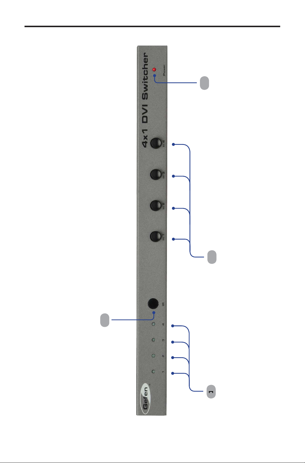
FRONT PANEL LAYOU
T
l
Front Pane
Page 9

FRONT PANEL DESCRIPTION
S
)
(
)
)
r
nput Indicators (1 - 4
Each of these LED indicators glows bright blue according to the current DVI
see
input selection
eceives IR signals from the included IR Remote Control Unit.
nput Buttons (1 - 4
Pressing each of these buttons selects the desired DVI input source (1 - 4).
owe
This LED indicator will glow bright red when the unit is powered..
nput Buttons, below
5
Page 10

BACK PANEL LAYOU
T
5
Back Panel
Page 11

BACK PANEL DESCRIPTION
S
C
t
f
f
R
5V D
onnect the included 5V DC locking power supply to this receptacle.
In
DVI Ou
4 RS-232
5 Ext I
- In
Each of these ports will accept a DVI source device.
This port will accept a single DVI output device. The currently selected DVI
input source will be output via this port.
This port is used
details, re
onnect an IR extender (Gefen part no. EXT-RMT-EXTIR) cable to this port.
er to page 16.
or serial communication using an RS-232 control device. For
7
Page 12

IR REMOTE CONTROL UNI
T
r
)
ese buttons are used to selec
source is routed to a mo
y
e
ayout and Description
Activity Indicato
This LED will be activated momentarily each time a button is pressed.
ource Selection Buttons (1 - 4
Th
NOTE: An Activity Indictor that fl ashes quickly while holding down
one of the sixteen buttons indicates a low battery. Replac
an
the IR Remote Control battery as soon as possible.
t which
nitor.
Page 13

IR REMOTE CONTROL UNI
T
y
y
y
.
y
y
structions
t
Installing the Batter
1.
2. Insert the included batter
The Remote Control unit ships with two batteries. One battery is required for
operation and the other batter
emove the battery cover on the back of the IR Remote Control Unit.
into the open battery slot. The positive (+) side of
the batter
.
eplace the battery cover
should be facing up.
is a spare.
Battery Slo
WARNING: Risk of explosion if battery is replaced by an
incorrect t
in
pe. Dispose of used batteries according to the
.
Page 14

C
S
g
IR REMOTE CONTROL UNI
T
0
)
e
fi
y
y
e
2
3
1
Setting the IR channel on the Remot
In the event that IR commands from other remote controls interfere with the
upplied IR Remote Control unit, changing the IR Remote Control’s IR channel
x the problem. The IR Remote Control unit has a bank of DIP switches used
will
or setting the IR channel. The DIP switch bank is located underneath the batter
ver.
eft: Picture of the
opened rear batter
ompartment of the IR
emote showing the
xposed DIP Switch
nk between th
battery chambers.
orresponding DIP Switch Settings for each IR Channel
IR Channel
default
ON
1 2
IR Channel
ON
1 2
1 2
IR Channel
ON
1 2
IR Channel
ON
1 2
It is important that the IR channel on the Remote Control unit, matches the IR
hannel set on the 4x1 DVI Switcher. For example, if both DIP switches on the
IR Remote
the 4x1 DVI
details on how to chan
ontrol unit are set to IR channel 0 (both DIP switches down), then
witcher must also be set to IR channel 0. See the next page for
e the IR channel on the 4x1 DVI Switcher.
10
Page 15

1
f
S
S
:
IR REMOTE CONTROL UNI
T
ese
1
2
3
Setting the IR channel on the 4x1 DVI Switcher
In order
or the IR Remote Control Unit to communicate properly with the
witcher, both the Remote and the Switcher must be set to the same IR channel.
The 4x1 DVI
witcher has a bank of eight (8) DIP switches on the bottom of the
nit. DIP switch 7 and 8 are used to set the IR channel for the Switcher. DIP
witches 1 - 6 are reserved for future expansion.
eft : DIP switch 7 and 8 on
the bottom of the Switcher.
DIP switches are in the
Th
default (OFF) position.
se the following settings for DIP switch 7 and 8 to set the IR channel on the 4x1
witcher
ON
7 8
DVI
IR Channel
ON
7 8
IR Channel
1
ON
7 8
IR Channel
ON
7 8
Page 16

CONNECTING THE 4X1 DVI SWITCHER
S
(Gef
S
g
A
How to Connect the 4x1 DVI Switcher
1
onnect up to four (4) computers to the DVI inputs on the back panel of the
witcher using the included DVI cables.
2
onnect a DVI display to the DVI output on the back panel of the Switcher.
onnect the included 5V locking power supply to the power receptacle on
the 4x1 DVI
4
onnect the AC power cord to an available electrical outlet.
PTIONAL: To use the RS-232 control, connect an RS-232 cable
between the
witcher and RS-232 host controller.
PTIONAL: To extend the range of the IR control, connect an IR
Extender
en part no. EXT-RMT-EXTIR) to the back of the Switcher.
witcher
Wirin
Diagram for the 4x1 DisplayPort Switcher
Computer
DVI CABLE
Computer
Computer
Computer
Switcher
TTENTION: This product should always be connected to a
rounded electrical socket.
12
Page 17

3
OPERATING THE 4X1 DVI SWITCHER
f
ying
f
g
S
:
f
Front Panel Buttons and LED Indicators
The
ront panel of the 4x1 DisplayPort Switcher has a set of four (4) LED
indicators, displa
indicators corresponds to one o
which input (source) is being displayed. Each of these LED
the push-buttons on the front panel.
Switchin
Example:
1 Press button 3 on the front panel of the 4x1 DisplayPort Switcher.
2 The LED indicator
witch to input 3 using the front-panel buttons
sources using the front-panel buttons
or input 3 will glow bright blue on the front panel.
1
Page 18

4
t
:
C
f
OPERATING THE 4X1 DVI SWITCHER
Switching sources using the IR Remote Control Uni
Example: Switch to Input 1 using the IR Remote Control
1 Press button 1 on the IR Remote Control Unit. The Activity Indicator on the
IT Remote
ontrol Unit will glow yellow, indicating that a button was pressed.
2 The LED indicator
or input 1 will glow bright blue.
1
Page 19

S
2
5 f
f
OPERATING THE 4X1 DVI SWITCHER
.
Switching sources using RS-232
onfi gure the Switch for use with RS-232 (see page 14 for details).
Example:
1Type
1
2 The LED indicator
witch to input 4 using RS-23
then press the Enter key to route the Switcher to Input 4. See page
or additional information on RS-232 commands.
erminal ready..
oute to Input 4
or Input 4 will glow bright green on the front panel.
15
Page 20

6
RS-232 CONTROL
8
e
1
e
A
y
1
1
ot
be
nly pins 2 (Receive), 3 (Transmit), and 5 (Ground) are used for communication.
A null-modem adapter should not be used with this product.
54321
9876
Only Pins 2 (RX), 3 (TX), and 5 (Ground) are used on the RS-232 serial interface
Serial Port Settings
Bits per second ............................................................................................ 19200
Data bits ...............................................................................................................
Parity ............................................................................................................. Non
top bits ................................................................................................................
Flow Control .................................................................................................. Non
SCII Corresponding RMT4-IR Binar
12345
6789
011 000
011 0010
0011 001
011 0100
NOTE: Only pins 2 (Receive), 3 (Transmit), and 5 (Ground) are
sed for communication. A null-modem adapter should n
sed with this product.
1
Page 21

SPECIFICATION
S
z
p
)
y)
y)
e
o
C
)
D
aximum Pixel Clock................................................................................165 MH
Input Video Signal................................................................................1.2 Volts p-
Input DDC Signal...........................................................................5 Volts p-p (TTL
DVI Input Connectors......................................(4) DVI-I 29-pin female (digital onl
DVI Output Connectors...................................(1) DVI-I 29-pin female (digital onl
-232 Connector.........................................................................(1) DB-9, femal
IR Extender Connector........................................................ (1) 3.5 mm mini-stere
Power Supply.................................................................................................5V D
Power Consumption........................................................................10 Watts (max.
Dimensions..........................................................................14” W x 1.2” H x 2.9”
hipping Weight..............................................................................................7 lbs.
17
Page 22

8
WARRANTY
f
f
y of
y
y
f of
g
f
Gef
y
g
y
g
y
y
N
.
efen warrants the equipment it manufactures to be free from defects in material
and workmanship.
I
equipment fails because of such defects and Gefen is notifi ed within two (2)
ears from the date of shipment, Gefen will, at its option, repair or replace the
quipment, provided that the equipment has not been subjected to mechanical,
lectrical, or other abuse or modifi cations. Equipment that fails under conditions
other than those covered will be repaired at the current price o
ect at the time of repair. Such repairs are warranted for ninety (90) days from
the da
reshipment to the Buyer.
parts and labor in
This warrant
without limitation, an
articular purpose, all of which are expressly disclaimed.
1. Proo
2.
The in
be accurate. However,
that ma
direct, indirect, special, incidental, or consequential dama
an
dama
For the latest warrant
Polic
ustomers outside the US are responsible for shipping charges to and from
efen.
.
opper cables are limited to a 30 day warranty and cables must be in their
ori
ormation in this manual has been carefully checked and is believed to
defect or omission in this manual, even if advised of the possibility of such
es. The technical information contained herein regarding the features and
pecifi cations is subject to change without notice.
under the Support section of the Gefen Web site at www.gefen.com.
is in lieu of all other warranties expressed or implied, including
implied warranty or merchantability or fi tness for any
sale may be required in order to claim warranty.
inal condition.
en assumes no responsibility for any inaccuracies
be contained in this manual. In no event will Gefen be liable for
es resulting from
coverage information, refer to the Warranty and Return
RODUCT REGISTRATIO
lease register your product online by visiting the Register Product page
nder the Support section of the Gefen Web site
1
Page 23

Page 24

ev A
8
Pb
This product uses UL listed or CE listed power supplies.
 Loading...