

Page 1
®
Page 2

ASKING FOR ASSISTANCE
Technical Support:
Telephone (818) 772-9100
(800) 545-6900
Fax (818) 772-9120
Technical Support Hours:
8:00 AM to 5:00 PM Monday thru Friday, Pacifi c Time
Write To:
Gefen, LLC.
c/o Customer Service
20600 Nordhoff St
Chatsworth, CA 91311
www.gefen.com
support@gefen.com
Notice
Gefen, LLC reserves the right to make changes in the hard ware, packaging, and
any accompanying doc u men ta tion without prior written notice.
DVI to HD-SDI Scaler Plus is a trademark of Gefen, LLC
© 2012 Gefen, LLC. All rights reserved.
All trademarks are the property of their respective owners
Rev A4
Page 3

CONTENTS
1 Introduction
2 Operation Notes
3 Features
4 Panel Layout
5 Panel Descriptions
6 IR Remote Control Unit Layout
7 IR Remote Control Unit Descriptions
8 Connecting the DVI to HDSDI Scaler Plus
9 IR Remote Control Unit Installation
10 Menu Functions
14 Supported Resolutions
15 Firmware Update Procedure
16 Specifi cations
17 Warranty
Page 4

1
INTRODUCTION
Congratulations on your purchase of the DVI to HDSDI Scaler Plus. Your
complete satisfaction is very important to us.
Gefen
Gefen delivers innovative, progressive computer and electronics add-on solutions
that harness integration, extension, distribution and conversion technologies.
Gefen’s reliable, plug-and-play products supplement cross-platform computer
systems, professional audio/video environments and HDTV systems of all sizes
with hard-working solutions that are easy to implement and simple to operate.
The Gefen DVI to HDSDI Scaler Plus
The Gefen DVI to HDSDI Scaler Plus combines SDI and DVI Equipment for
maximum Interoperability
It is the newest revision of our HDSDI conversion line incorporating single
link DVI-D conversion scaled to SD/HDSDI Single link modes. Resolutions of
up to 1080p are supported over the HDSDI link for those that want true “High
Defi nition.” Performance has been greatly enhanced due to Gennum’s VXP
Scaler onboard, allowing for new features such as Color and Gamma Correction, Noise Reduction, Detail Enhancement, Aspect Ratio Selection, Pattern
Generator Mode, and Multiple Language Menu Support.
How It Works
DVI devices are connected to the DVI input and SDI devices are connected
to the SDI output. When the source, display and the Scaler are powered and
connected, video signals are converted to the proper format.
Page 5

2
OPERATION NOTES
READ THESE NOTES BEFORE INSTALLING OR
OPERATING THE DVI TO HDSDI SCALER PLUS
• On power up, the DVI to HDSDI Scaler Plus will automatically detect the
input format.
• The Native resolution for the DVI to HDSDI Scaler Plus is 1080i.
• To Restore factory settings, cycle power on the Scaler.
Page 6

3
FEATURES
Features
• Maximum active image size of 2048 samples x 2048 lines PBP processing
for various combinations of video and graphics with alpha blending
10-bit resolution for greater precision and dynamic range.
• Proprietary 10-bit motion adaptive video de-interlacing with edge interpolation
for HD / SD formats.
• Supports Dolby Digital (AC-3) and multichannel PCM audio.
• Advanced noise reduction and detail enhancement
• Fully integrated sprite-based multi-plane OSD controller.
• Frame rate conversion to / from any refresh rate
• Pattern mode with color bars and cross hatch patterns
• Color correction
• Noise Reduction
• Detail Enhancement
• Brightness Adjustment
• Gamma Selection
• Aspect Ratio Select
• Custom Timing output mode
• French/English Menu Set
• RS-232 upgradable fi rmware
• Remote control using RS-232 and/or IR
• Rack Mountable
Package Includes
(1) Gefen DVI to HDSDI Scaler Plus
(1) 6 ft. DVI cable (M-M)
(1) IR Remote Control Unit
(1) 6 ft. DB-9 cable (M-F)
(1) 5V DC Locking Power Supply
(1) Set of Rack Ears
(1) Quick-Start Guide
Page 7
4
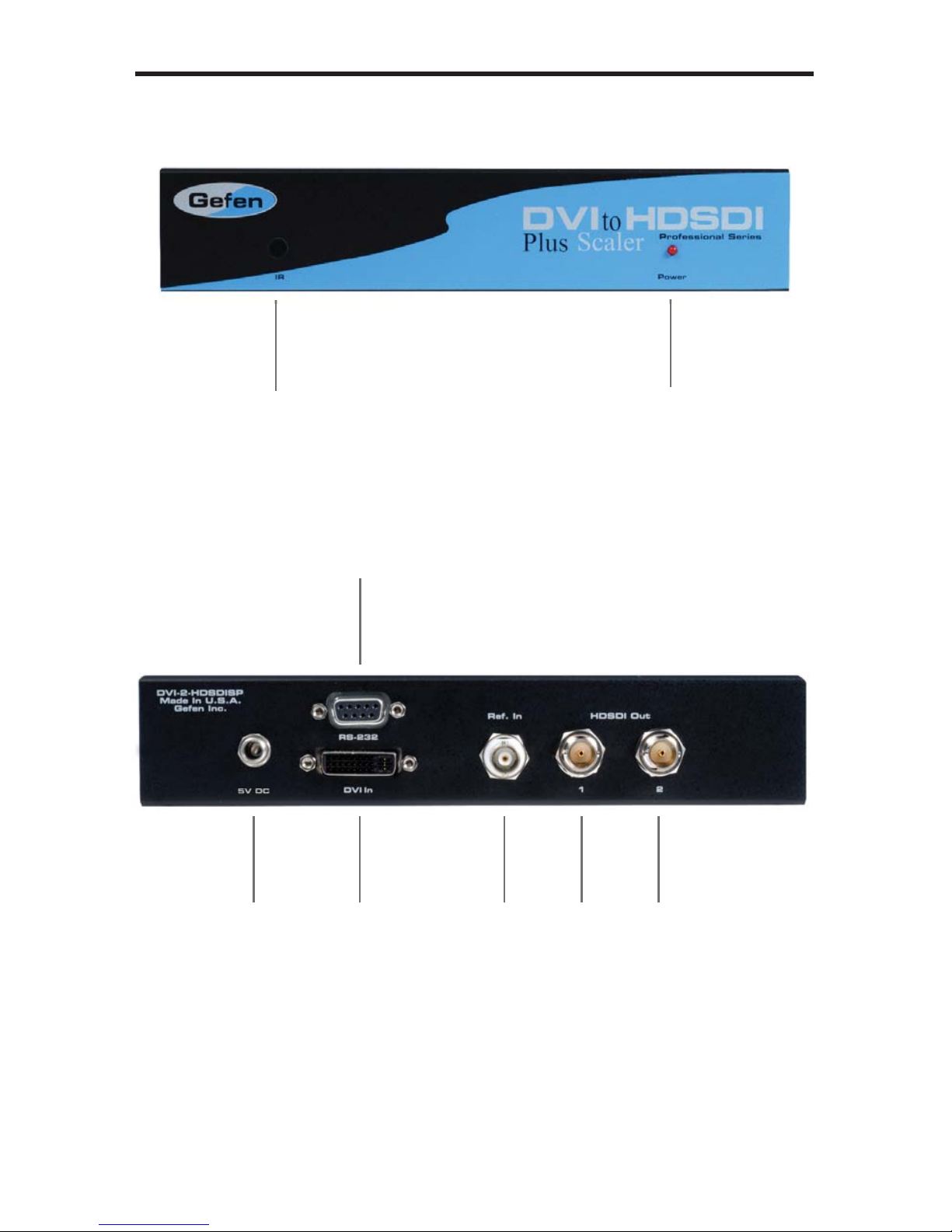
PANEL LAYOUT
Front
Back
1
2
4
3
5
6
7
8
Page 8

5
PANEL DESCRIPTIONS
1 Infrared Sensor
Detects IR signals from remote control.
2 Power on LED
When this LED is lit the unit is powered up.
3 RS-232 Port
Connect a RS-232 control device to this port.
4 5V DC Locking Power Connector
Connect the included 5V DC power supply to this port.
5 DVI Input
Connect a DVI source to this input.
6 Reference Input
Connect an external clock to this port.
7 HDSDI Out 1
Connect a suitable SDI display here.
8 HDSDI Out 2
Connect a second SDI cable between the scaler when using dual link
resolutions or if using two displays.
Page 9

6
IR REMOTE CONTROL UNIT LAYOUT
RMT-8HDS-IR Remote Control Unit
1
2
3
8
7
4
6
5
Page 10

7
IR REMOTE CONTROL UNIT DESCRIPTIONS
1 LED Signal
This LED will fl ash each time a command is entered using one of the keys.
2 UP Arrow
This key is used to navigate upwards in the on-screen menu.
3 LEFT Arrow
This key is used to navigate left in the on-screen menu.
4 SOURCE Key
This key selects the input source (Input 1 or Input 2).
5 DOWN Arrow
This key is used to navigate down in the on-screen menu.
6 OUTPUT Key
Cycles the DVI to HDSDI Scaler Plus through the output modes (640x480,
800x600, 720p and 1080i).
7 MENU Key
This key brings up the on-screen menu.
8 RIGHT Arrow
This key is used to navigate right in the on-screen menu.
Page 11

8
CONNECTING THE DVI TO HDSDI SCALER PLUS
How to Connect the DVI to HDSDI Scaler Plus
1. Connect the DVI source to the DVI input on the DVI to HDSDI Scaler Plus
using the supplied DVI cable.
2. Connect the SDI output device to the HDSDI output on the DVI to HDSDI
Scaler Plus.
3. Connect the included 5V DC locking power receptacle to the DVI to HDSDI
Scaler Plus.
4. Plug the power supply into an available electrical outlet.
HD-SDI CABLE
Scaler
Computer
HD-SDI Monitor
DVI CABLE
Wiring Diagram for the DVI to HDSDI Scaler Plus
Page 12

9
IR REMOTE CONTROL UNIT INSTALLATION
1. Remove battery cover from the back of the IR Remote Control Unit.
2. Verify that DIP switch 1 and DIP switch 2 are in the down (OFF) position.
3. Insert the battery, hold the battery so that you can see the positive side facing up. The side that is not marked must be facing down.
4. Test the IR Remote Control Unit by pressing ONLY one button at a time. The
indicator light on the remote will fl ash once each time you press a button.
WARNING: Do not press multiple buttons simultaneously and do NOT press
buttons rapidly. These actions will cause the remote to reset and steps 1-4
will have to be repeated.
Note: The IR Remote Control Unit ships with two batteries. One battery is
required for operation, the second battery is complimentary.
The following are the DIP switch combinations that correspond to the Remote
Code menu option on the DVI to HDSDI Scaler Plus (please see OSD Menu
Functions section on page 10 for more information).
1
2
Remote Channel 0:
1
2
Remote Channel 1:
1
2
Remote Channel 2:
1
2
Remote Channel 3:
Page 13

10
MENU FUNCTIONS
Aspect:
• Full Screen:
Stretches input to fi ll the Monitor.
• Letter / Pillar Box:
Sets the aspect ratio to fi t a letter or pillar box format. SSP
• Panoramic:
Panoramic Zoom feature
• Extract: Feature to magnify the signal.
• Extract Size: Adjusts signal magnifi cation.
• Horizontal / Vertical Position:
Moves the magnifi ed signal Horizontally and Vertically
• Through:
Feature to crop the signal.
• Horizontal / Vertical Size:
Horizontally and Vertically contracts or expands the cropping viewport.
• Horizontal / Vertical Position:
Move the signal Horizontally or Vertically inside the cropping viewport.
• Layout:
Feature to Resize Image resolution.
• Size and Position:
• Horizontal / Vertical Size:
Adjust Horizontal or Vertical resolution.
• Horizontal / Vertical Position:
Move image Horizontally or Vertically.
Page 14

11
MENU FUNCTIONS
Picture:
Image Color:
• Contrast:
Individually adjust the contrast for red, green and blue
• Brightness:
Individually adjust the brightness for red, green and blue
• Black level:
Adjust black levels between 0 (default) and 100
Detail Enhancement:
• Detail Enhancement:
Digitally enhance signal
• Noise Threshold:
Adjusts noise allowed in detail enhancement
• Noise Reduction:
Digitally reduce signal noise
• Motion Threshold
Page 15

12
MENU FUNCTIONS
Input Video Format:
• Auto Detect by default.
Signal can be forced to a specifi c High-defi nition resolution.
Input Graphic Format:
• Auto Detect by default.
Signal can be forced to a specifi c computer resolution.
Clean Aperture:
• Horizontal and Vertical Size: Stretch image Horizontally or Vertically
• Horizontal and Vertical Position: Move image in view port Horizontally or
Vertically
• Remote Channel: Changes the I/R code of the Scaler to one of 4 settings
between 0 and 3 (which in turn set the I/R frequency in use. )
The I/R code must be set the same in both I/R remote and Scaler. The
Remote uses DIP Switches; the Scaler uses this menu function.
(See the IR Remote Control Unit Installation on page 9 for more information.)
Input Color Range:
• Auto
16 - 235 (limited range RGB)
0 - 255 (full range RGB)
Page 16

13
MENU FUNCTIONS
Output:
• Output Format: Select the desired output resolution.
• Genlock Reference: Genlock Reference: Synchronizes the DVI input video
source with an external SDI input source or reference signal. The SDI
output will be genlocked. Note that the input and output frequencies must be
multiples of one another.
• Language:
Set menu to display English or French text.
Gamma Correction:
• Default:
Set for Default Gamma settings: sRGB
• Custom:
Enables Gamma Coeffi cient menu item as the current Gamma coeffi cient.
• Gamma Coeffi cient:
(0.3 - 3.0); Default set at 1.0.
Patterns:
• Color Bars:
Display color bar video pattern.
• Cross Hatch:
Display cross hatch video pattern.
Page 17

14
SUPPORTED RESOLUTIONS
Input Video Formats Supported:
480i 720p/50 1080p/23.98 2K-p/23.98
480p 720p/59.94 1080p/24 2K-p/24
576i 720p/60 1080p/25
576p 1035i/59.94 1080p/29.97
720p/23.98 1035i/60 1080p/30
720p/24 1080i/50 1080p/50
720p/25 1080i/50M 1080p/50M
720p/29.97 1080i/59.94 1080p/59.94
720p/30 1080i/60 1080p/60
Input Graphic Formats Supported:
640x350/85 1024x768/75 1280x1024/85 1080p/60
640x400/85 1024x768/85 1360x768/60 1920x1200/60
640x480/60 1280x854 1366x768/60 2048x1080
640x480/75 1152x864/75 1366x923/50
640x480/85 1280x768/60 1440x900/60
800x600/60 1280x960/60 1440x1080/60
800x600/75 1280x960/85 1600x1024
800x600/85 1280x1024/60 1600x1200/60
1024x768/60 1280x1024/75 1680x1050/60
Output video formats supported:
480i 720p/50 1080p/23.98 1080sf/23.98
480p/59.94 720p/59.94 1080p/24 1080sf/24
576i 720p/60 1080p/25 1080sf/25
576p/50 1035i/59.94 1080p/29.97 1080sf/29.97
720p/23.98 1035i/60 1080p/30 1080sf/30
720p/24 1080i/50 1080p/50 2K-p/23.98
720p/25 1080i/50M 1080p/50M 2K-p/24
720p/29.97 1080i/59.94 1080p/59.94 2K-sf/23.98
720p/30 1080i/60 1080p/60 2K-sf/24
Page 18

15
FIRMWARE UPDATE PROCEDURE
Check http://www.gefen.com/kvm/support/download.jsp for fi rmware updates and
procedures.
Page 19

16
SPECIFICATIONS
Input Video Bandwidth...............................................................................165 MHz
Output Video Bandwidth..................................................................2 x 1.485 Gbps
Maximum Input Resolution.....................................................................2048x1080
Maximum Output Resolution.............................................................2048x1080/24
DVI Connector.......................................................DVI-I 29 pin female (digital only)
SDI/HDSDI Connector....................................................................(2) BNC, female
Data Port...........................................................................................................DB9
Power Supply.................................................................................................5V DC
Power Consumption........................................................................20 watts (max.)
Dimensions.....................................................................8.25” W x 1.75” H x 7.5” D
Shipping Weight..............................................................................................5 lbs.
Page 20

WARRANTY
17
Gefen warrants the equipment it manufactures to be free from defects in material
and workmanship.
If equipment fails because of such defects and Gefen is notifi ed within two (2)
years from the date of shipment, Gefen will, at its option, repair or replace the
equipment, provided that the equipment has not been subjected to mechanical,
electrical, or other abuse or modifi cations. Equipment that fails under conditions
other than those covered will be repaired at the current price of parts and labor in
effect at the time of repair. Such repairs are warranted for ninety (90) days from
the day of reshipment to the Buyer.
This warranty is in lieu of all other warranties expressed or implied, including
without limitation, any implied warranty or merchantability or fi tness for any
particular purpose, all of which are expressly disclaimed.
1. Proof of sale may be required in order to claim warranty.
2. Customers outside the US are responsible for shipping charges to and from
Gefen.
3. Copper cables are limited to a 30 day warranty and cables must be in their
original condition.
The information in this manual has been carefully checked and is believed to
be accurate. However, Gefen assumes no responsibility for any inaccuracies
that may be contained in this manual. In no event will Gefen be liable for
direct, indirect, special, incidental, or consequential damages resulting from
any defect or omission in this manual, even if advised of the possibility of such
damages. The technical information contained herein regarding the features and
specifi cations is subject to change without notice.
For the latest warranty coverage information, refer to the Warranty and Return
Policy under the Support section of the Gefen Web site at www.gefen.com.
PRODUCT REGISTRATION
Please register your product online by visiting the Register Product page
under the Support section of the Gefen Web site.
Page 21

This product uses UL listed power supplies.
20600 Nordhoff St., Chatsworth CA 91311
1-800-545-6900 818-772-9100 fax: 818-772-9120
www.gefen.com support@gefen.com
Rev A4
Pb
 Loading...