

Geemarc PHOTOPHONE 450 User Manual

PHOTOPHONE 450
Amplified Big Button
Telephone
With Photo Dial
English
0

CONTENTS
SETTINGS
SETTINGS SETTINGS
!!!Please refer to our website: www.geemarc.com for an up to
date user guide, as there may be important updates and changes
you need to be aware of !!!
CONTENTS .................................................................................. 1
INTRODUCTION .......................................................................... 3
Unpacking the Telephone ............................................................. 4
DESCRIPTION ............................................................................ 5
General Description ...................................................................... 5
Key Description ............................................................................ 7
LCD Description ........................................................................... 7
INSTALLATION ........................................................................... 8
Setting Up ..................................................................................... 8
Wall Mounting ............................................................................... 8
Table Mounting ........................................................................... 10
SETTINGS .................................................................................. 11
Set Language ............................................................................. 11
Set LCD Contrast ...................................................................... 11
Set Date and Time ...................................................................... 12
Set Flash Time ........................................................................... 12
Set Service Access ..................................................................... 13
Set Tone (Dialling Mode) ............................................................ 13
Set Ringer Volume ..................................................................... 14
Set Ringer Tone ......................................................................... 14
Receiving Volume ...................................................................... 14
Handset Volume Boost Button .................................................... 14
USING THE TELEPHONE ......................................................... 16
Making a Call .............................................................................. 16
Last Number Redial .................................................................... 17
Dialling a Number from the Redial List ....................................... 17
Call Timer ................................................................................... 17
1

CONTENTS
Receiving a Call .......................................................................... 17
Hearing Aid Use ......................................................................... 17
OPTIONAL ACCESSORIES ...................................................... 18
Flash Signal ................................................................................ 18
Headset ..................................................................................... 18
CALLER ID ................................................................................ 19
View Caller ID List ...................................................................... 19
Dial a Number from the Caller ID List ......................................... 19
Add a Number from the Caller ID List to the Phone Book .......... 20
Delete a Number from the Caller ID List ..................................... 20
Delete all Numbers from the Caller ID List.................................. 20
Caller ID on Call Waiting ............................................................ 20
PHONE BOOK ........................................................................... 21
Create a Phone Book Entry ........................................................ 21
View Phone Book Entries ........................................................... 22
Dial a Phone Book Entry ............................................................ 22
Modify a Phone Book Entry ........................................................ 23
Delete a Phone Book Entry ........................................................ 24
Delete all Phone Book Entries .................................................... 24
PHOTO DIAL ............................................................................. 25
Create a Photo Dial Number ....................................................... 25
View/Dial a Photo Dial Number .................................................. 25
Clear a Photo Dial Number ......................................................... 25
SERVICE ACCESS .................................................................... 26
Calling a Service Number ........................................................... 26
TROUBLESHOOTIING .............................................................. 27
SAFETY INFORMATION ........................................................... 28
GUARANTEE ............................................................................. 29
RECYCLING DIRECTIVES ........................................................ 30
2
INTRODUCTION
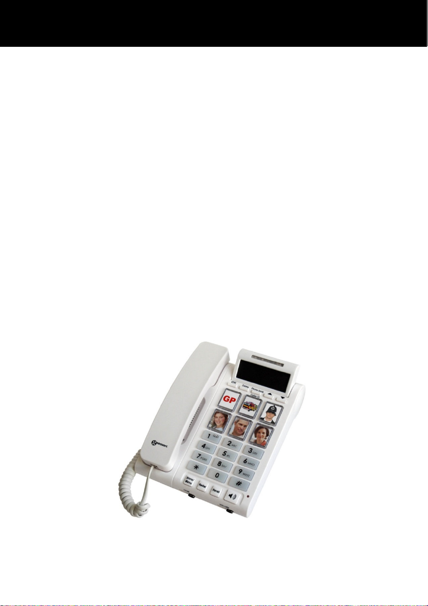
Congratulations on purchasing your Geemarc PHOTOPHONE
450 which has been developed in conjunction with Action on
Hearing Loss in the UK. This is a multifunction telephone which
offers features such as hands free use, caller ID* and a phone
book. It offers handset amplification and a loud ringer, helpful for
those with hearing loss. It has large buttons, and an easy to see
and use keypad to help stop any misdialling. It has photo dial
buttons designed to make dialling easier you will be able to
identify speed dial buttons with pictures of your family and friends.
This telephone is also compatible with hearing aids.
Since this telephone has handset amplification, it is capable of
producing loud volume levels.
It is important that you read the instructions below in order to use
your Geemarc telephone to its full potential. Keep this user guide
in a safe place for future reference.
This guide explains how to use the PHOTOPHONE 450
3

INTRODUCTION
Unpacking the Telephone
When unpacking the telephone, you will find the following in the
box:
• 1 PHOTOPHONE 450
• 1 PHOTOPHONE 450 handset with curly cord
• 1 Telephone line cord
• 1 Mains power adaptor
• 1 User Guide
For product support and help visit our website at
www.geemarc.com
telephone 01707 387602
or fax 01707 832529
4
DESCRIPTION
t
yp
Sp
DESCRIPTION
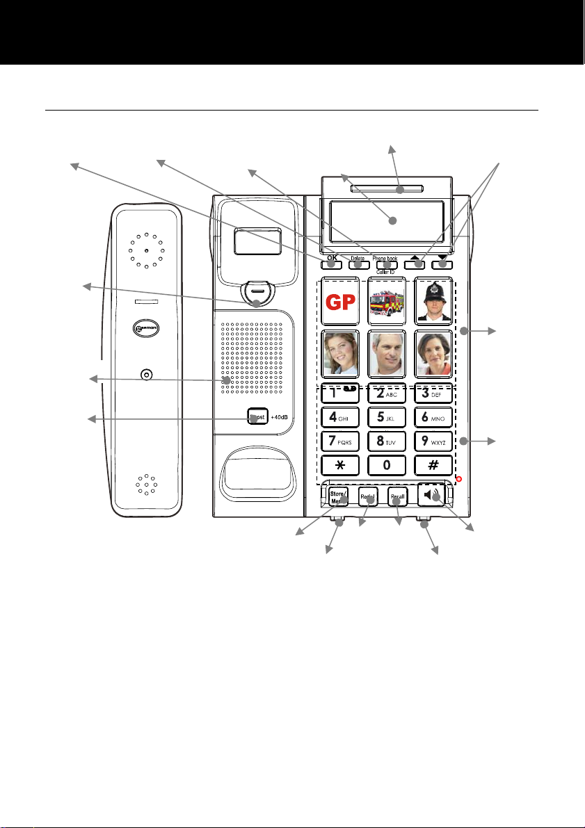
General Description
Confirm/OK
Handset
Holder
eaker
Amplify
Delete/Clear
Phonebook/
Caller ID Lis
Menu/Store
Tone slider
Ringer indicator/
New call LED
LCD screen
Redial
R key
Volume slider
Loud speaker
Scroll up/
Photo
Dial
Numeric
ke
ad
5
DESCRIPTION
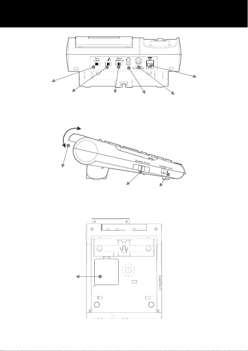
Ringer tone
Volume boost
reset override
LCD
screen tilt
Ringer volume
Loudspeaker
volume
slider
Headset
jack
Handset
cord jack
Phone line cord jack
Power jack
Battery
compartment
6
Key Description
y
g
g
y
DESCRIPTION
Store/Menu
Redial
Recall
Delete
Phone book /
Caller ID
and
Boost (+40dB)
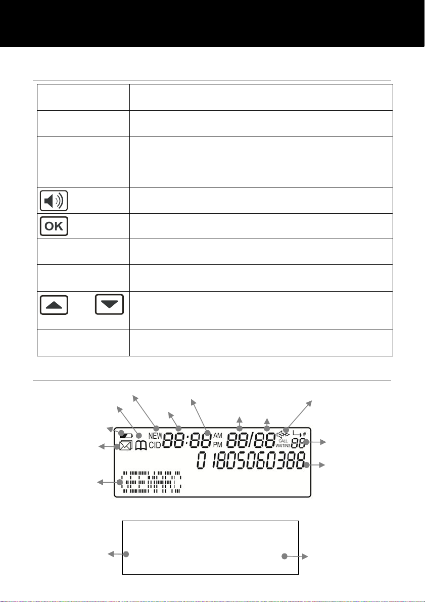
LCD Description
Phonebook mode
Battery strength
Voice message
Caller ID mode
Enter the change settings menu.
Store numbers to memor
.
Last number redial.
Insert a pause when pre-dialin
a number.
This button is used to disconnect a call and reestablish dial tone or to switch over to another
caller provided you have requested these services
i.e. call waitin
from your service provider.
Make/Answer/End a call.
Activates the speakerphone if pressed during a call.
Confirm Setting/Make Call.
Delete incorrect digits or characters.
Delete an entr
in Phone Book or Caller ID List.
Toggle between Caller ID list and Phone book
Scroll through the menu options. Move through a
number or name when in edit mode.
Enter the Caller ID list
Press this button to switch the handset
amplification ON or OFF.
Hours
Minutes
Day
Loudspeaker ON
Month
Numeric position
in Caller ID list
Character area/
Name display
Digit area/Number
display
In standby mode, the large LCD display will show as below
Total calls
received
TOTAL: 07 NEW:02
12:00 01/01
New calls received
(not reviewed)
7

INSTALLATION
Setting Up
The telephone requires four good quality non-recharable AAA
batt eries. These are not supplied with your telephone. Carefully
remove the battery compartment cover-found on the underside of
the telephone base .We suggest using the tip of a ball point pen to
open the cover. Check the battery polarity diagrams when inserting
the batteries. Fit the battery cover back on.
Connect one end of the curly cord to the handset. The other end
of the curly cord plugs into the jack on the left hand side of the
PHOTOPHONE 450 unit marked Handset Cord. Place the handset
on the cradle.
Connect the line cord to the socket located at rear of telephone then
connect the plug into the wall socket* *.
For the LCD display, backlight and other special features you must
use the power adapter (batteries act as a backup in case of power
failure). Connect the power adaptor to the jack located at the rear of
the telephone marked DC9V then plug the other end into a 13amp
mains power wall socket (*). Please choose a socket near your
telephone to enable you to unplug the mains power quickly in case
of a problem.
(*) Classified “hazardous voltage” according to EN60950 standard
(**) Classified TNV-3 according to EN60950 standard.
Wall Mounting
Rotate the handset hanger tab 180 degrees (see diagram 1).
This will keep the handset from falling out of the cradle when it
is mounted on the wall.
Knock two self-tapping screws (not supplied) into a wall at a distance
of 85 mm from each other and placed in a vertical line. Leave the
screws protruding from the wall by 6mm (see diagram 2).
Feed the guide tabs on the wall-mounting bracket into the slots at
the bottom of the telephone. Slide the bracket upwards until it
8
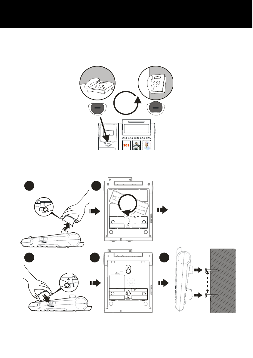
INSTALLATION
snaps into place. Now place the telephone over the screws and
push it downwards (slightly).
Place the phone onto the screw-heads and slide down to secure.
O
180
Diagram 1
1 2
o
180
3 4 5
Diagram 2
9
85CM
 Loading...