

Page 1
Quick Starter Manual for PrusaM201
Page 2

Copyright Declaration
The copyright of this specification belongs to the Shenzhen GETECH CO., LTD. (hereinafter
referred to as the "Geeetech"), and all rights reserved. No part of this specification should be
reproduced or extracted in any forms or means without the prior written consent of Geeetech by any
company and individuals.
Technical Support
If you are interested in the technology of 3 D printing, flight control and U-home, welcome to
Geeetech, we have series of made-up products, main boards, modules and a variety of peripherals
for you. Or if you are looking for relevant information or technical support, please login our forum
where you can find anything you want about open source. To know more about our new products,
please visit www.geeetech.com, we will serve you wholeheartedly.
Page 3

Contents
Quick Starter Manual for PrusaM201...........................................................................................................................1
Copyright Declaration...................................................................................................................................................2
Technical Support......................................................................................................................................................... 2
Contents........................................................................................................................................................................ 3
1 Install USB Driver..................................................................................................................................................... 1
2 Download and install Repetier-Host..........................................................................................................................1
3 Repetier-Host setting................................................................................................................................................. 2
4 Function test...............................................................................................................................................................7
4.1 Homing........................................................................................................................................................... 8
4.2 Directions of X, Y, Z motor............................................................................................................................ 9
4.3 Heating..........................................................................................................................................................10
4.4 Extruder.........................................................................................................................................................11
4.5 LCD...............................................................................................................................................................16
5 Heat bed leveling..................................................................................................................................................... 19
6 Slice 3r setting..........................................................................................................................................................21
6.1 Import STL files............................................................................................................................................21
6.2 Slicing........................................................................................................................................................... 23
7 Introduction of new function................................................................................................................................... 29
7.1 Mixer.............................................................................................................................................................29
Print alternating color................................................................................................................................. 32
Blending color.............................................................................................................................................33
Gradient color............................................................................................................................................. 34
7.2 Introduction of customizable gradient template...........................................................................................35
7.2.1 Parameters Setting Instructions:........................................................................................................ 36
7.2.2 Custom Template Setting...................................................................................................................36
7.2.3 Printing Effect Demonstration...........................................................................................................39
7.3 Introduction of Printer Settings.................................................................................................................... 40
8. FAQ.........................................................................................................................................................................46
Page 4
GEEETECH
www.geeetech.com Tel: +86 755 2658 4110 Fax: +86 755 2658 4074 - 858
ShenZhen GETECH CO.,LTD
- 1 -
1 Install USB Driver
1.1 Windows update will automatically update and install the driver.
Connecting USB, and there is a prompt in the bottom right corner of desktop, showing that the
driver is installing the device driver software.
1.2 If your computer can’t install the driver automatically, please manually install the
driver according to following method.
Download the USB driver and click installation.
http://www.ftdichip.com/Drivers/CDM/CDM%20v2.12.00%20WHQL%20Certified.exe
2 Download and install Repetier-Host
Download and install Repetier-Host. Please choose the corresponding version of
Windows/Mac/Linux according to your operating system.
Windows: http://www.repetier.com/download-now/
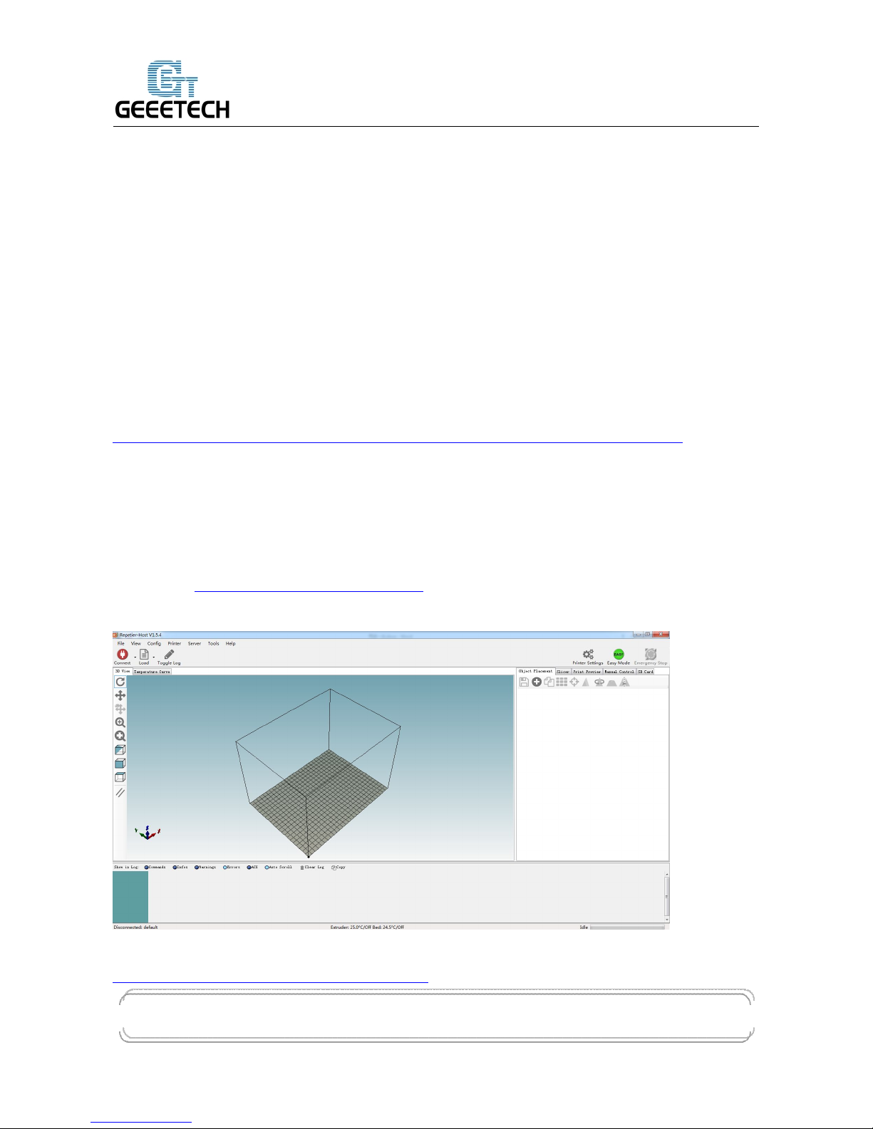
After installation, open Repetier-Host.
For starters, you can read following link to get information about how to use Repetier-Host.
http://www.geeetech.com/wiki/index.php/Repetier-Host
Page 5
GEEETECH
www.geeetech.com Tel: +86 755 2658 4110 Fax: +86 755 2658 4074 - 858
ShenZhen GETECH CO.,LTD
- 2 -
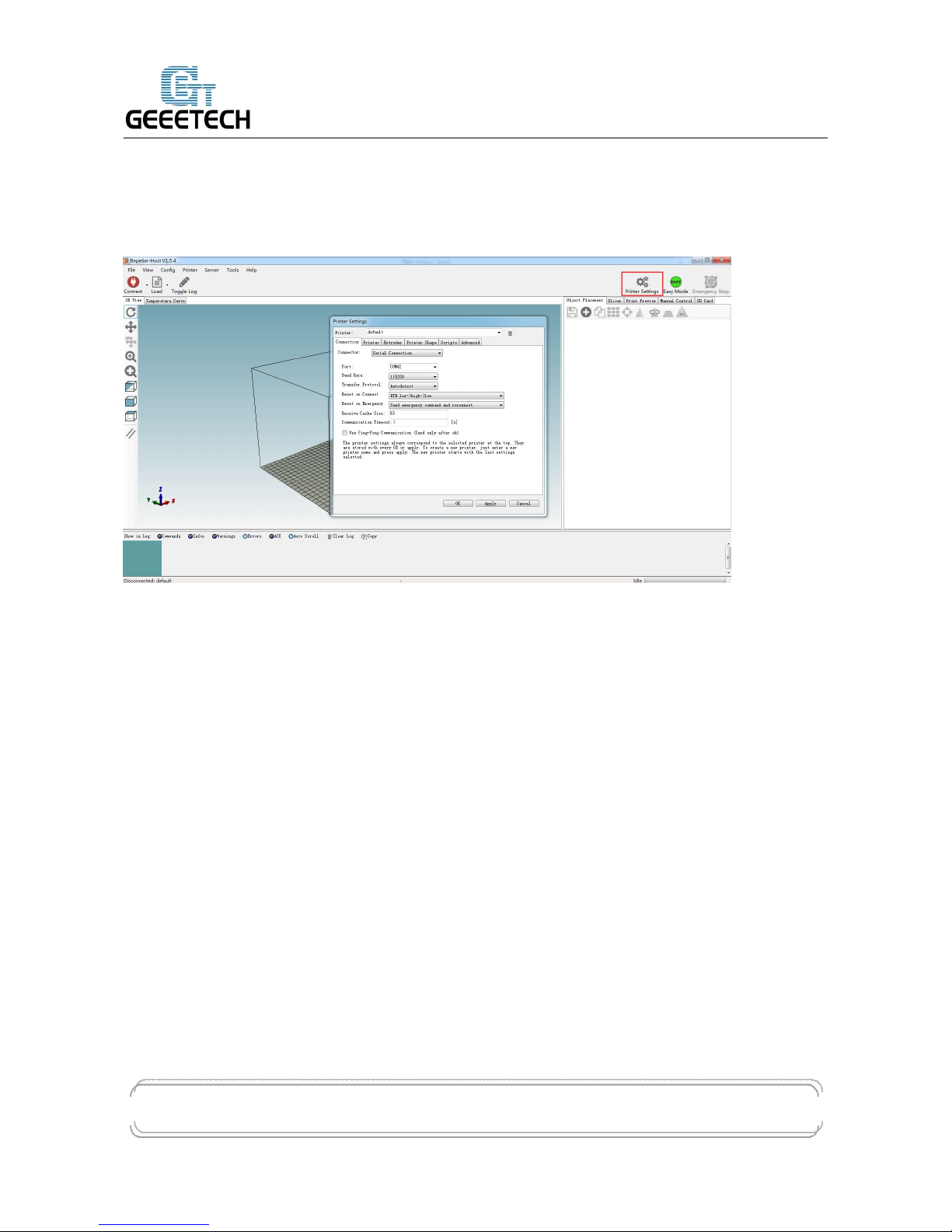
3 Repetier-Host setting
Before printing, please set following parameters.
Click the Printer Settings, and the interface of printer setting will appear.
Set following parameters in printer settings
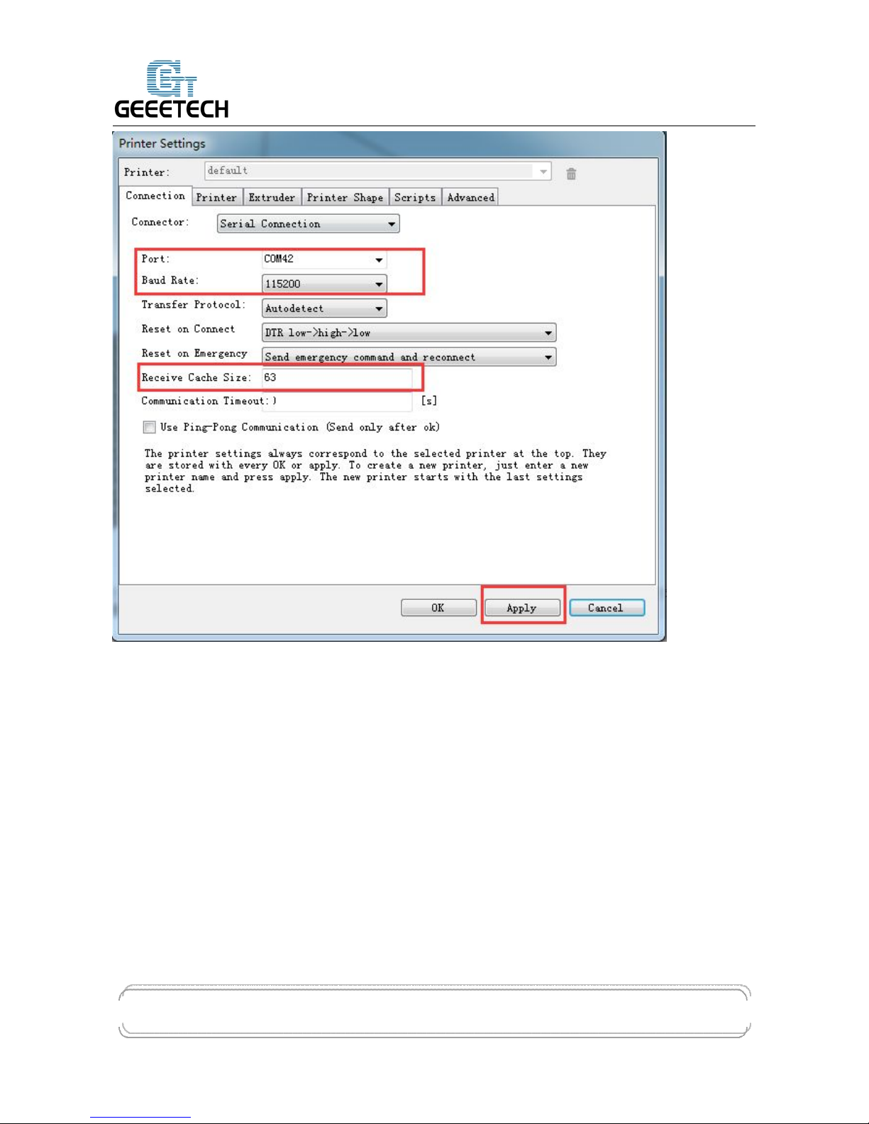
1. Connection
Choose the right printer port, Baud rate and Receive Cache Size. For other settings please choose
the default parameter, and then click Apply.
Port: correspondence with the port in device manager
Baud Rate: 115200
Receive Cache Size: 63
Page 6
GEEETECH
www.geeetech.com Tel: +86 755 2658 4110 Fax: +86 755 2658 4074 - 858
ShenZhen GETECH CO.,LTD
- 3 -
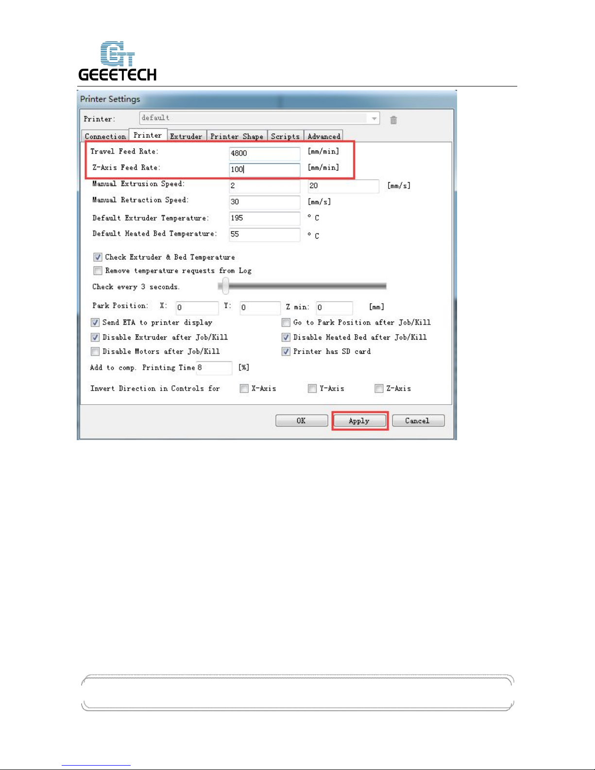
2. Printer
Set the printer’s moving speed in direction of X, Y and Z axis. For other settings please choose the
default parameter, then click Apply.
Page 7
GEEETECH
www.geeetech.com Tel: +86 755 2658 4110 Fax: +86 755 2658 4074 - 858
ShenZhen GETECH CO.,LTD
- 4 -
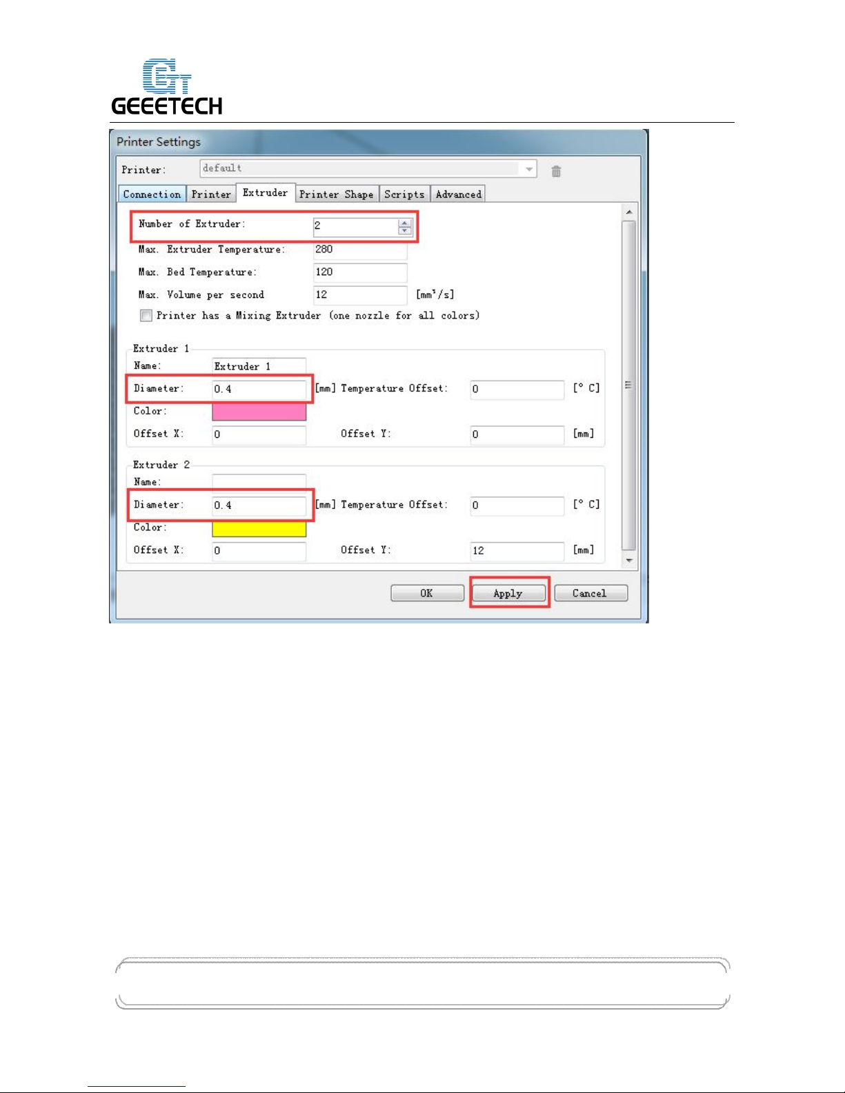
3. Extruder
Set the number of extruder as 2, and set the nozzle diameter. For other settings please choose the
default parameter, then click Apply.
You need set the nozzle diameter according to the diameter of extruder head you purchased. If
you can’t confirm the diameter, please contact the manufacturer to get right parameter.
Page 8
GEEETECH
www.geeetech.com Tel: +86 755 2658 4110 Fax: +86 755 2658 4074 - 858
ShenZhen GETECH CO.,LTD
- 5 -
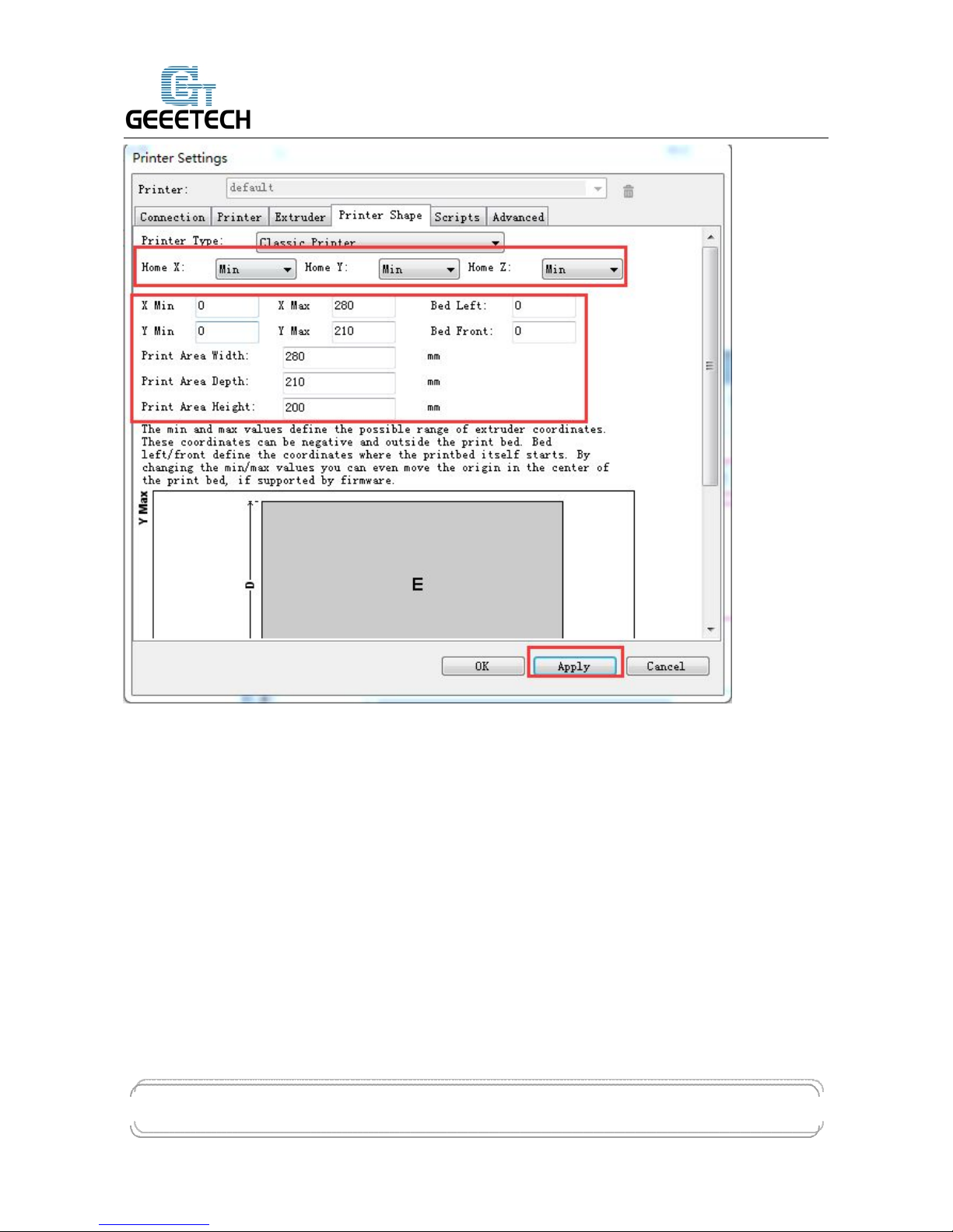
4. Printer shape
Set home position and printing platform parameters.
Printer type:choose Classic Printer
Page 9
GEEETECH
www.geeetech.com Tel: +86 755 2658 4110 Fax: +86 755 2658 4074 - 858
ShenZhen GETECH CO.,LTD
- 6 -
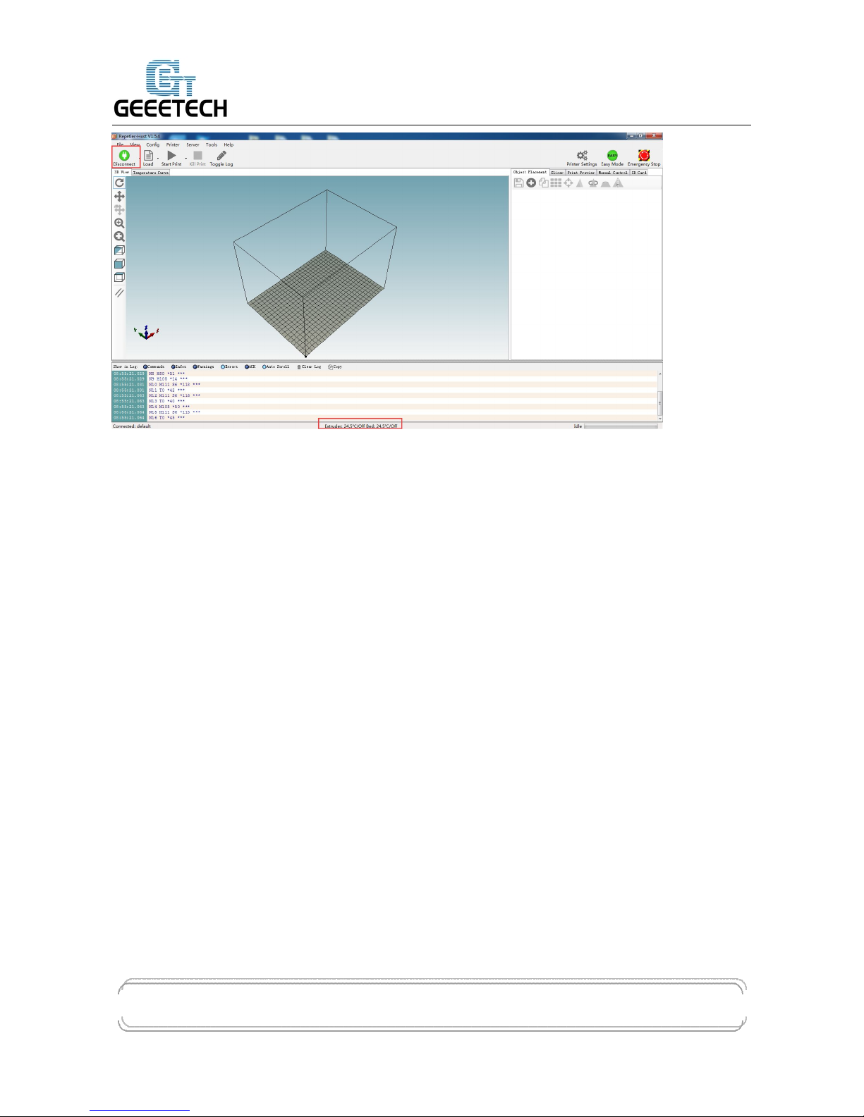
After successfully finishing the printer settings, click the Connect in the top left corner. If the icon
turns green, it means the printer is successfully connected with upper computer.
Page 10
GEEETECH
www.geeetech.com Tel: +86 755 2658 4110 Fax: +86 755 2658 4074 - 858
ShenZhen GETECH CO.,LTD
- 7 -
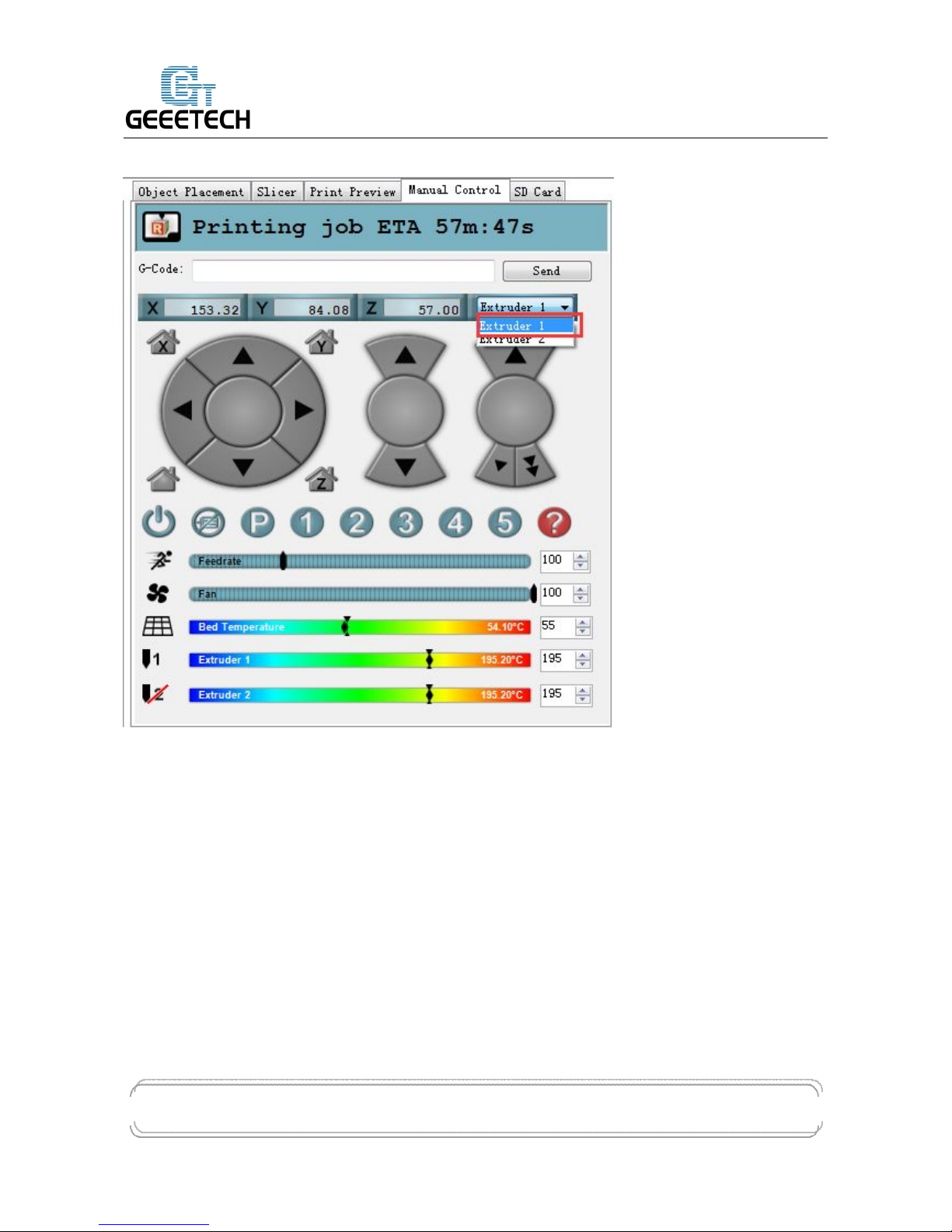
4 Function test
When upper computer is successfully connected, don’t print immediately. You should test each part
of the printer to see if they can work normally.
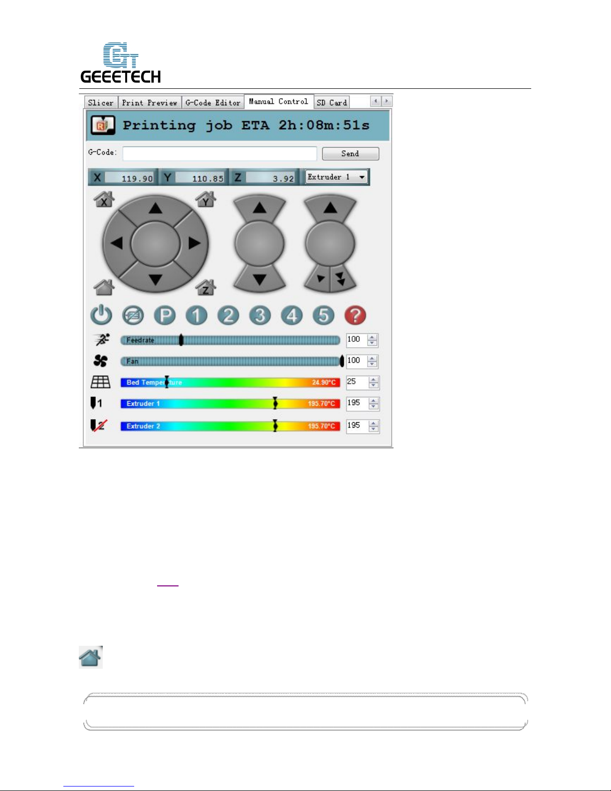
Following picture is the manual control panel of upper computer
Page 11
GEEETECH
www.geeetech.com Tel: +86 755 2658 4110 Fax: +86 755 2658 4074 - 858
ShenZhen GETECH CO.,LTD
- 8 -
Tests you should do are as following:
4.1 Homing
Separately set X, Y and Z axis as zero, and three coordinate axes will move to the direction of
endstop. At this moment please observe if the homing direction is right or not. If it is not right,
please refer to FAQ.
Home X: X axis moves to home position
Home Y: Y axis moves to home position
Home Z: Z axis moves to home position
:means X, Y and Z axis simultaneously moves to home position.
Page 12

GEEETECH
www.geeetech.com Tel: +86 755 2658 4110 Fax: +86 755 2658 4074 - 858
ShenZhen GETECH CO.,LTD
- 9 -
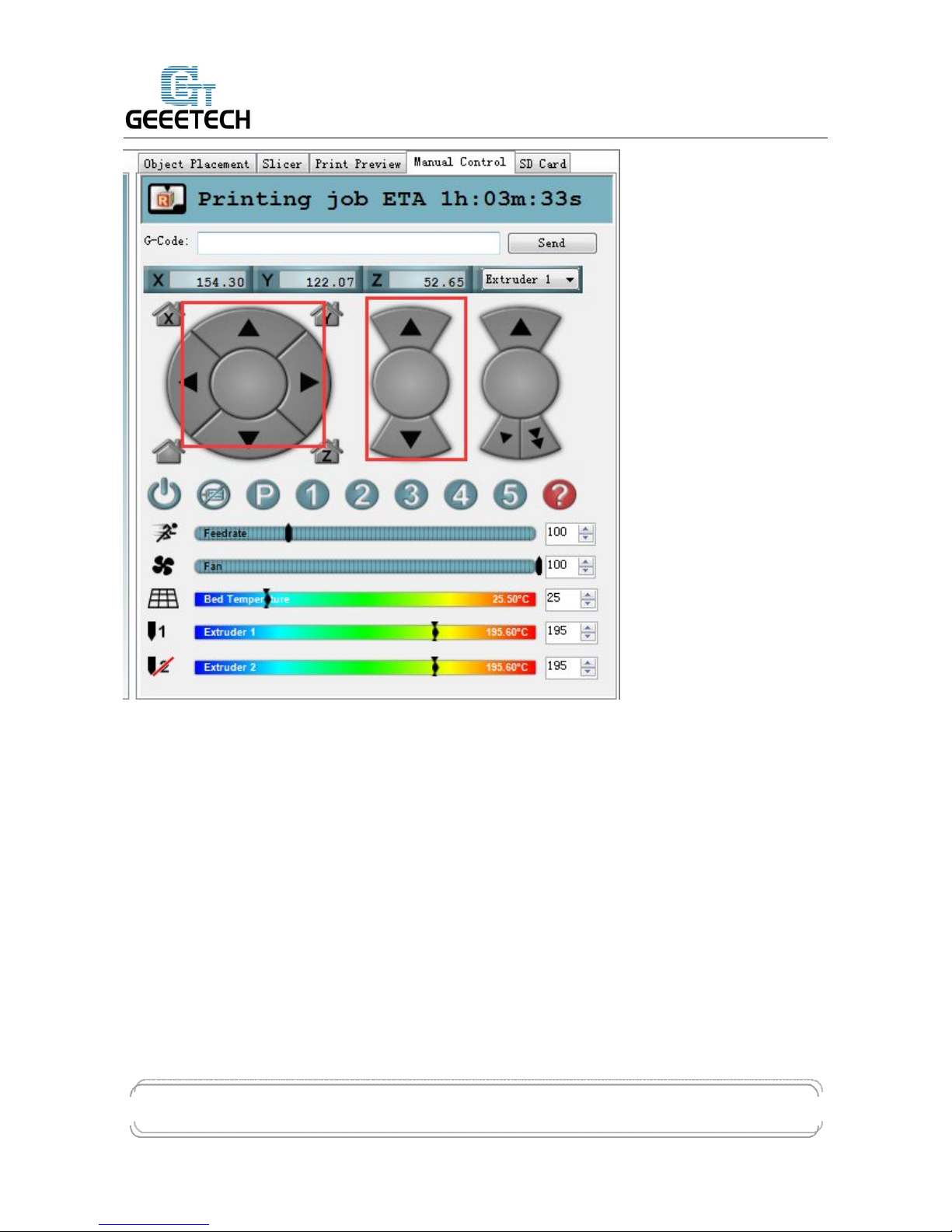
4.2 Directions of X, Y, Z motor
Click the arrows in the icon to test if the directions of X, Y and Z motor are right. If the direction is
reversed, please modify the logic value of corresponding motor. For specific solution, please refer
to FAQ.
Page 13
GEEETECH
www.geeetech.com Tel: +86 755 2658 4110 Fax: +86 755 2658 4074 - 858
ShenZhen GETECH CO.,LTD
- 10 -
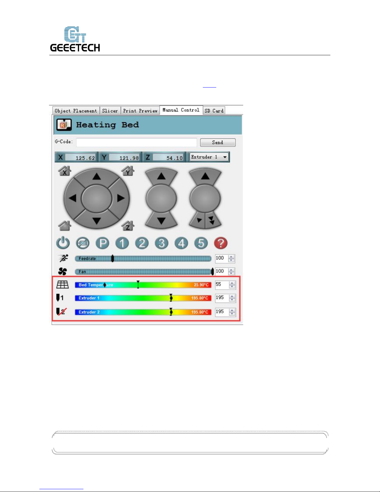
4.3 Heating
Here you can set the heating temperature of heat bed and extruder. Temperature of extruder can not
be set too high or too low, otherwise the extruder can easily have blockage. You need adjust the
temperature according to your filament.
Generally speaking,
PLA:extruder 190°-210°/heat bed:55°
ABS:extruder 240°-250°/ heat bed:75°-80°, In order to make the filament stick on the heat
bed easily, please add ABS glue on the printing platform.
Notice: we set the number of extruder as 2, but actually there is only one nozzle. When you are
heating extruder 1, extruder 2 is also heated by default. Therefore, you don’t need
Page 14
GEEETECH
www.geeetech.com Tel: +86 755 2658 4110 Fax: +86 755 2658 4074 - 858
ShenZhen GETECH CO.,LTD
- 11 -
simultaneously heat extruder 1 and 2.
If you can’t heat extruder or heat bed, please refer to FAQ.
At this moment, heat bed, extruder 1 and extruder 2 are separately heated up to 55℃ and 195℃.
4.4 Extruder
After the extruder reaches the preset temperature, we need to make sure filament0 and filament1 are
both working.
Notice:
At any time, please make sure that filament 0 and filament 1 are simultaneously inserted into the
nozzle. Don’t only insert filament 0 or filament 1. Otherwise, once no matter which kind of filament
Page 15
GEEETECH
www.geeetech.com Tel: +86 755 2658 4110 Fax: +86 755 2658 4074 - 858
ShenZhen GETECH CO.,LTD
- 12 -
is fused too much, it will overflow upwards and then block the hole through which the other kind of
filament enters the heating block from the barrel.
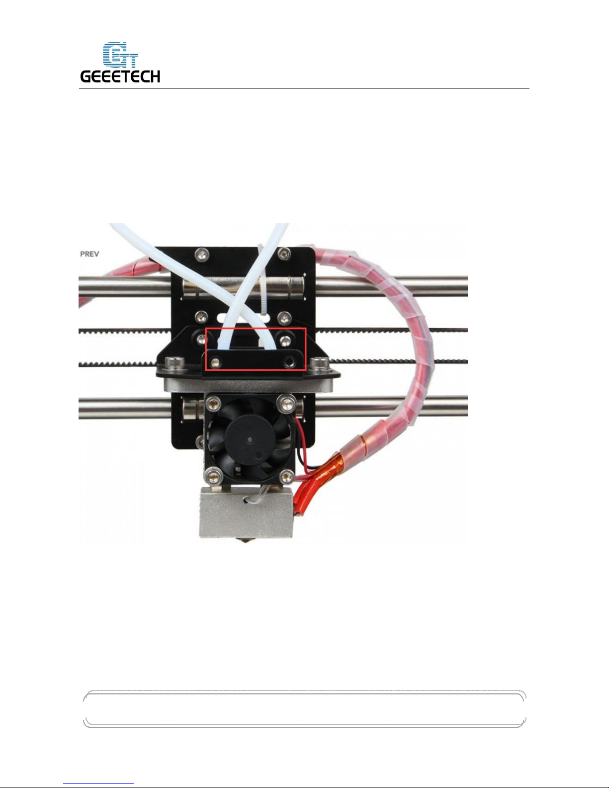
No matter in the process of cleaning filament or inserting and removing the filament, don’t insert or
remove the feeding pipe near the hot end. Once the filament in it is fused too much and feeding
pipe is not inserted entirely, the fused filament will overflow up and then cause blockage. If this
kind of problem happens, it will be difficult to clean the filament.
Page 16
GEEETECH
www.geeetech.com Tel: +86 755 2658 4110 Fax: +86 755 2658 4074 - 858
ShenZhen GETECH CO.,LTD
- 13 -
Test extruder 1
Click the downward arrow to test if filament 0 can be discharged fluently. In order to avoid
blockage, please extrude filament at 1mm or 0.1 mm. You can use one hand to hold the filament,
and it will be helpful for you to know the conditions of the rotation of extruder motor and moving
of filament.
Page 17

GEEETECH
www.geeetech.com Tel: +86 755 2658 4110 Fax: +86 755 2658 4074 - 858
ShenZhen GETECH CO.,LTD
- 14 -
If filament can’t be extruded fluently or there is blockage, you will hear a sound of clicks.
Please refer to FAQ.
Page 18

GEEETECH
www.geeetech.com Tel: +86 755 2658 4110 Fax: +86 755 2658 4074 - 858
ShenZhen GETECH CO.,LTD
- 15 -
Choose extruder 2, repeat the steps of extruder 1. And test if filament 1 can be extruded fluently.
Page 19

GEEETECH
www.geeetech.com Tel: +86 755 2658 4110 Fax: +86 755 2658 4074 - 858
ShenZhen GETECH CO.,LTD
- 16 -
4.5 LCD
You can also test if these functions are normal or not through LCD.
Enter LCD>Prepare
Page 20

GEEETECH
www.geeetech.com Tel: +86 755 2658 4110 Fax: +86 755 2658 4074 - 858
ShenZhen GETECH CO.,LTD
- 17 -
In the menu of prepare, you can do 6 kinds of operations including Disable steppers/Auto
home/Preheat PLA/ Preheat ABS/Cool down/move axis. Followings are explains for each of them.
1. Disable stepper: X,Y, Z motor unlocking. When the motor is unlocked, X, Y and Z axis can
be moved manually.
2. Auto Home: three axes move to home position at the same time
3. Preheat PLA:extruder and heat bed are separately heated to preset temperature: 200℃,70℃.
Page 21

GEEETECH
www.geeetech.com Tel: +86 755 2658 4110 Fax: +86 755 2658 4074 - 858
ShenZhen GETECH CO.,LTD
- 18 -
4. Preheat ABS: extruder and heat bed are separately heated to preset temperature: 240℃,95℃.
You can also enter LCD<control<temperature<preheat PLA conf to modify the preset temperature.
Set the preset temperature of extruder and heat bed.
If you want to stop heating, please enter control<temperature and manually adjust the temperature
to 0.
Page 22

GEEETECH
www.geeetech.com Tel: +86 755 2658 4110 Fax: +86 755 2658 4074 - 858
ShenZhen GETECH CO.,LTD
- 19 -
5. Move axis
X,Y,Z axis can move at a resolution of 10mm, 1mm and 0.1mm.
Extruder 1 and extruder 2 can only move at a resolution of 1mm and 0.1mm.
5 Heat bed leveling
You need do leveling for nozzle and four corners of the heat bed. Next is one of the leveling
methods.
Rough adjustment
There is a Z axis endstop trigger (M3*50 screw) on the left end of X axis. Tightness of the spring
determines the reset position of the Z axis. Through adjusting M3*50 screw, try to make the reset
position of Z axis the same with the position where the extruder head exactly stops on the heat bed.
Page 23

GEEETECH
www.geeetech.com Tel: +86 755 2658 4110 Fax: +86 755 2658 4074 - 858
ShenZhen GETECH CO.,LTD
- 20 -
Fine adjustment of the relative location between extruder head and heat bed
1. Set Z axis to initial position
2.
After unlocking the motor, manually move X axis and Y axis, and move the extruder to four
corners of the heat bed in turn. Because of former rough adjustment, the extruder head is very
close to the heat bed.
3. Put a piece of flat A4 paper in the inter space between extruder head and heat bed, then drag the
paper to test if there is a slight resistance. If there is, it means the extruder head is already at the
right position. If not, you need adjust the screw of this corner of the heat bed to slightly raise or
lower the heat bed.
Page 24

GEEETECH
www.geeetech.com Tel: +86 755 2658 4110 Fax: +86 755 2658 4074 - 858
ShenZhen GETECH CO.,LTD
- 21 -
4.
Move the extruder head to other three corners, and adjust their corresponding screws.
6 Slice 3r setting
Following setting is just for reference, you need set different slicing parameters according to actual
printing models and filament.
6.1 Import STL files
You can download here.
Page 25

GEEETECH
www.geeetech.com Tel: +86 755 2658 4110 Fax: +86 755 2658 4074 - 858
ShenZhen GETECH CO.,LTD
- 22 -
After successful import, if you need, you can do operations on the items in object placement
including placing it in the middle/enlarging it/rotating it.
Page 26

GEEETECH
www.geeetech.com Tel: +86 755 2658 4110 Fax: +86 755 2658 4074 - 858
ShenZhen GETECH CO.,LTD
- 23 -
6.2 Slicing
Click slicer>configuration, slicer3r window will prompt up.
Page 27

GEEETECH
www.geeetech.com Tel: +86 755 2658 4110 Fax: +86 755 2658 4074 - 858
ShenZhen GETECH CO.,LTD
- 24 -
Click file>load config in the top left corner,and import M201 slicing configuration. Download it
here.
Page 28

GEEETECH
www.geeetech.com Tel: +86 755 2658 4110 Fax: +86 755 2658 4074 - 858
ShenZhen GETECH CO.,LTD
- 25 -
Import Normal.ini slicing configuration
Page 29

GEEETECH
www.geeetech.com Tel: +86 755 2658 4110 Fax: +86 755 2658 4074 - 858
ShenZhen GETECH CO.,LTD
- 26 -
After successfully importing Normal.ini slicing configuration, click save in print settings label.
Set filament parameters in filament settings, and click save.
Notice: please check Keep fan always on and Enable auto cooling in the tab of cooling. This is for
avoiding blockage.
Page 30

GEEETECH
www.geeetech.com Tel: +86 755 2658 4110 Fax: +86 755 2658 4074 - 858
ShenZhen GETECH CO.,LTD
- 27 -
In the tab of printer settings
After you saving above slicing configuration, return to slicer
Click the drop-down box of print settings/printer settings/filament settings, the slicing configuration
which was just save as Normal.ini will appear. Choose this slicing parameters, and click slice with
slic3r to do slicing for imported printing model.
Page 31

GEEETECH
www.geeetech.com Tel: +86 755 2658 4110 Fax: +86 755 2658 4074 - 858
ShenZhen GETECH CO.,LTD
- 28 -
In the process of slicing
Page 32

GEEETECH
www.geeetech.com Tel: +86 755 2658 4110 Fax: +86 755 2658 4074 - 858
ShenZhen GETECH CO.,LTD
- 29 -
When slicing is finished, click print to begin printing.
7 Introduction of new function
7.1 Mixer
Mixer is used to adjust the mixing proportion of two kinds of filaments in order to realize the
Page 33

GEEETECH
www.geeetech.com Tel: +86 755 2658 4110 Fax: +86 755 2658 4074 - 858
ShenZhen GETECH CO.,LTD
- 30 -
printing effect of different colors and blending colors.
There is a menu in Mixer shown as following list:
Prepare used for returning to upper Prepare Menu
Filament 0: displaying current proportion of Filament 0. Press to enter, the value can be adjusted.
Filament 1: displaying current proportion of Filament 1. Press to enter, the value can be adjusted.
Note: extruder 1 is corresponding to filament 0, extruder 2 is corresponding to filament 1
The sum of the proportion of Filament 0 and Filament 1 is 100% . If you manually adjust either of
the two values, system will automatically work out the other value. The proportion will not change
unless you readjusting it or choosing template again.
OFP: Over Fusion Protect. Through restricting the proportion of filaments, OFP can avoid
blockage caused by the long-time stay in the extruder and over fusion carbonization of the two
kinds of filaments. It can also avoid bad printing effects brought by filament’s over-softness after
over-fusion. This function is turned on by default. When it is turned on, the maximum proportion
of filament is no more than 96%, and the minimum proportion is not less than 4%.
Page 34

GEEETECH
www.geeetech.com Tel: +86 755 2658 4110 Fax: +86 755 2658 4074 - 858
ShenZhen GETECH CO.,LTD
- 31 -
You can also modify the OFP proportion
OFP Max: maximum proportion of filament feeding
OFP Min: minimum proportion of filament feeding
Store Memory: save
If it is not saved, the printer will agree that current parameters are valid. After restarting the printer,
last setting is recovered.
Templates: Menu entrance of blending template. Used for the storage of blending templates.
The following is Templates menu. Templates are used for printing gradient color effect.
Template 1: Once this template is chosen, Filament 1 will change to Filament 0 within the height of
2mm;
Template 2: Once this template is chosen, Filament 0 will change to Filament 1 within the height of
2mm;
Template 3: Once this template is chosen, Filament 0 will change to Filament 1 within the height of
10mm;
Template 4:Once this template is chosen, Filament 1 will change to Filament 0 within the height of
10mm;
Template 5:Once this template is chosen, Filament 0 will change to Filament 1 within the height of
20mm;
Template 6:Once this template is chosen, Filament 1 will change to Filament 0 within the height of
20mm;
Template 7:Once this template is chosen, Filament 0 will change to Filament 1 within the height of
50mm;
Template 8:0nce this template is chosen, Filament 1 will change to Filament 0 within the height of
50mm;
Both of manual adjustment and choosing template can change the blending proportion. It will come
Page 35

GEEETECH
www.geeetech.com Tel: +86 755 2658 4110 Fax: +86 755 2658 4074 - 858
ShenZhen GETECH CO.,LTD
- 32 -
into effect immediately and the proportion is determined by the last operation.
Print alternating color
You can use M201 to print alternating color like using other printers with dual extruders. Please
calculate the printing time in advance, and adjust the proportion of filament 0 and filament 1 when
it is time to change color.
Method 1:
Change filament 0:96%, filament1:4% to filament 0:4%,filament 1:96%,and this is changing
from filament 0 to filament 1.
Method 2:
Select template 1, switch from filament 0 to filament 1
Select template 2, switch from filament 1 to filament 0
Page 36

GEEETECH
www.geeetech.com Tel: +86 755 2658 4110 Fax: +86 755 2658 4074 - 858
ShenZhen GETECH CO.,LTD
- 33 -
Blending color
Manually adjusting the proportion of filament 0 and filament 1 can realize different blending colors.
Page 37

GEEETECH
www.geeetech.com Tel: +86 755 2658 4110 Fax: +86 755 2658 4074 - 858
ShenZhen GETECH CO.,LTD
- 34 -
Gradient color
Choose LCD<MIXER<Templates, and there are 4 pairs, 8 kinds of gradient colors for choosing.
Following pictures are separately corresponding to the gradient effects from template 1 to template
8. You can change the template you want to use at any time and any stage.
Page 38

GEEETECH
www.geeetech.com Tel: +86 755 2658 4110 Fax: +86 755 2658 4074 - 858
ShenZhen GETECH CO.,LTD
- 35 -
7.2 Introduction of customizable gradient template
Custom template allows user to set the parameters of gradient color printing. It provides six
customizable templates for user to set and they are named as Custom1 to Custom6. User can set
Page 39

GEEETECH
www.geeetech.com Tel: +86 755 2658 4110 Fax: +86 755 2658 4074 - 858
ShenZhen GETECH CO.,LTD
- 36 -
under the Mixer >Custom menu. Each template includes parameters of Start Gradient Percent, End
Gradient Percent, Start Height, and End Height. Perform a Store Memory to Save it when the
setting is done.
Next i will show you how to set and use a customized template.
7.2.1 Parameters Setting Instructions:
1. All the settings are set based on Filament0 by default.
2. According to the work principle of Mixer, the sum feeding rate of Filament0 and Filament1 is
100%. After Filament0 is set, the system will automatically calculate the corresponding feeding rate
of Filament1.
3. Start percent and end percent can be set at will. The sum of them is not always 100%. Users can
adjust it according to their requirements.
E.g., you can set the start percent of Filament0 as 30% and the end percent 60%.
Filament0
Filament1
Total
Start percent
30%
70%
100%
End percent
60%
40%
100%
Total
90%
110%
4. Start height and end height are print heights above the bed not the current printing height. Start
height and end height must be greater than current printing height, otherwise they will be regarded
as invalid. For example, current height is 40mm above the bed, but the start height in the template
setting is 20mm and the end height is 30mm. It has overlapped part with current print height, so the
system will automatically ignore this template and continue printing with the current template.
5. When one templates is finished, printing will continue with the feed rate percent that is fixed,
without gradient effect, until you choose a new template.
7.2.2 Custom Template Setting
Page 40

GEEETECH
www.geeetech.com Tel: +86 755 2658 4110 Fax: +86 755 2658 4074 - 858
ShenZhen GETECH CO.,LTD
- 37 -
1 Open Mixer->Custom on LCD control panel:
Let’s take custom 1 as example.
Here we set custom 1 conf as follows:
Start Percent: 30%
Page 41

GEEETECH
www.geeetech.com Tel: +86 755 2658 4110 Fax: +86 755 2658 4074 - 858
ShenZhen GETECH CO.,LTD
- 38 -
End Percent: 60%
Start Height: 0mm
End Height: 30mm
When the setting is done, please press Store memory to save it:
Similarly you can set other custom templates, for example, custom 2:
Start Percent: 60%
End Percent: 20%
Start Height: 30mm
End Height: 60mm
(note, there is no overlapped height)
Page 42

GEEETECH
www.geeetech.com Tel: +86 755 2658 4110 Fax: +86 755 2658 4074 - 858
ShenZhen GETECH CO.,LTD
- 39 -
The templates which have been set can be found in Mixer->Templates.
You can change setting parameters at any time during the printing process. When the setting is done,
you can start printing. Select the corresponding template in Mixer-> Templates during the printing
process.
Note: the“*” after the template means the current template you are choosing and using. System will
follow your last chosen operation by default.
7.2.3 Printing Effect Demonstration
The following picture shows the printing effect after the combination of Custom1 and Custom2.
Filament 0: red
;
Filament 1: yellow
Page 43

GEEETECH
www.geeetech.com Tel: +86 755 2658 4110 Fax: +86 755 2658 4074 - 858
ShenZhen GETECH CO.,LTD
- 40 -
7.3 Introduction of Printer Settings
Printer Settings is used to adjust some parameters of the printer and save them through Store
memory.
Choose LCD<control<printer settings
Page 44

GEEETECH
www.geeetech.com Tel: +86 755 2658 4110 Fax: +86 755 2658 4074 - 858
ShenZhen GETECH CO.,LTD
- 41 -
1. Set the printing volume of the printer
X Max: 280 // X Max refers to maximum coordinate of X axis
X Min: 0 // X Min refers to minimum coordinate of X axis
Y Max: 210 // Y Max refers to maximum coordinate of Y axis
Y Min: 0 // Y Min refers to minimum coordinate of Y axis
Z Max: 200 // Z Max refers to maximum coordinate of Z axis
Z Min: 0 // Z Min refers to minimum coordinate of Z axis
Page 45

GEEETECH
www.geeetech.com Tel: +86 755 2658 4110 Fax: +86 755 2658 4074 - 858
ShenZhen GETECH CO.,LTD
- 42 -
You can set the printing volume of the printer through above parameters. When setting is finished,
choose Control<store memory to save the parameters.
2. Set home position
Home X: MIN //Home X refers to the position of X axis after homing, and it can be set as Max
Page 46

GEEETECH
www.geeetech.com Tel: +86 755 2658 4110 Fax: +86 755 2658 4074 - 858
ShenZhen GETECH CO.,LTD
- 43 -
or Min
Home Y: MIN //Home Y refers to the position of Y axis after homing, and it can be set as
Max or Min
Home Z: MIN //Home Z refers to the position of Z axis after homing, and it can be set as
Max or Min
Notice: under normal conditions, the homing position is set as Min by default. Please don’t modify
this parameter at will.
You can set the homing position of the printer through above parameters. When setting is finished,
choose store memory to save the parameters.
3. Set motor direction
X Motor Dir: False // X Motor Dir refers to the running direction of X motor
Page 47

GEEETECH
www.geeetech.com Tel: +86 755 2658 4110 Fax: +86 755 2658 4074 - 858
ShenZhen GETECH CO.,LTD
- 44 -
Y Motor Dir: True // Y Motor Dir refers to the running direction of Y motor
Z Motor Dir: True // Z Motor Dir refers to the running direction of Z motor
E Motor Dir: True // E Motor Dir refers to the running direction of E0 motor
E1 Motor Dir: True // E1 Motor Dir refers to the running direction of E1 motor
Above setting is the default setting of M201. If you find your motor direction is reversed, you can
change the motor direction through modifying this logic value.
4. Set endstop logic level
Page 48

GEEETECH
www.geeetech.com Tel: +86 755 2658 4110 Fax: +86 755 2658 4074 - 858
ShenZhen GETECH CO.,LTD
- 45 -
Logic level refers to logic active level
Status refers to on/off state of endstop, NO (Normally Open), NC (Normally Close)
Page 49

GEEETECH
www.geeetech.com Tel: +86 755 2658 4110 Fax: +86 755 2658 4074 - 858
ShenZhen GETECH CO.,LTD
- 46 -
endstop of M201 is set by default as:
Logic level: High
Status: NC
5. Print speed setting.
Rotate the knob can adjust the printing speed during printing. It is 100% as default.
8. FAQ
1. Homing direction or motor direction is reversed.
If you have this problem, please modify the logic value of corresponding motor in the menu of
control>printer settings of LCD. Change the motor direction of corresponding axis from True to
False or change it from False to True.
2. Instruction for the heating of extruder 2
In Repetier-Host, we set the number of extruder on M201 as 2, which means there are 2 extruder
motors but only one hot end. You don’t need simultaneously heat extruder 1 and extruder 2.
Extruder 2 is heated by default when extruder 1 is heated.
Page 50

GEEETECH
www.geeetech.com Tel: +86 755 2658 4110 Fax: +86 755 2658 4074 - 858
ShenZhen GETECH CO.,LTD
- 47 -
3. Extruder can’t be heated
For this problem, please check following electronic components
1) If the power supply works normally.
2)If there is a poor contact between the heating wire and the socket of control board. You should
make the copper wire in the heating wire have a good contact with the cooper sheet of the
socket.
3) There is an open circuit in somewhere of the hot end and heating wire (resistance is infinite),
which causes no current passing through.
4) MOSFET may be burned-out.
4. Extrusion is not fluent or blockage problem
1)Whether the temperature setting of printer is proper or not. There are different melting
temperatures of different filaments, and please choose proper heating temperature. Filament
is easy to get carbonized when the temperature is too high; while the extrusion of filament
will become less fluent when the temperature is too low.
2)The hot end cannot dissipate heat in time. Maybe this is because the fan wire of the hot end
has a poor contact with the socket, which causes the fan of hot end stopping working.
3)The inter space between the nozzle tip and heat bed is too small, and this causes difficult
extrusion. In order to get a proper space you can do like this: after z axis going back to
home position, put an A4 paper between the nozzle and the heat bed and you can slide the
paper under slight resistance.
4)The filament faces a large resistance in the path from the extruder to the nozzle. The
resistance may be produced by the motor, feeding pipe or nozzle.
5)The torsion of the extruder motor is insufficient. You can adjust the potentiometer on
A4988 to enhance the current.
If there is blockage, please refer to following steps to solve it.
1) Heat the extruder to the temperature of the melting point of the filament.
2) Press the lever of the extruder motor and pull out the filament. If the filament is broken in the
feeding pipe, please refer to step 4.
Page 51

GEEETECH
www.geeetech.com Tel: +86 755 2658 4110 Fax: +86 755 2658 4074 - 858
ShenZhen GETECH CO.,LTD
- 48 -
3) Check the filament which has been taken out. If it has a sign of being slightly broken, please cut
it off and reinsert the filament.
4) When you are inserting or pulling out the feeding pipe which is close to the hot end, it is easy to
block the nozzle completely if your operation is not proper. Please mind your operation.
Mark the current inserting depth of the feeding pipe in the barrel. Press the blue quick plug above
the barrel and pull out the feeding pipe. Clean out the filament which is stuck in the pipe, then
reinsert feeding pipe. Please notice that the depth of inserting the pipe should be the same with
before. If the depth of inserting is shallower than before, melted filament will overflow upwards
and takes up the place of feeding pipe, which makes the filament harder to enter the nozzle.
5) If you find too much filament gets accumulated in the hot end, please use needle to clean out
surplus filament. Then reinsert feeding pipe and filament. This process doesn’t need too much
strength; otherwise the PTFE in the barrel will easily be stuck to broken.
Page 52

GEEETECH
www.geeetech.com Tel: +86 755 2658 4110 Fax: +86 755 2658 4074 - 858
ShenZhen GETECH CO.,LTD
- 49 -
If you still have any problem, please turn to our forum for help. Our tech support will help you
resolve them.
 Loading...