


A10
1
SHENZHEN GETECH TECHNOLOGY CO., LTD
Geeetech A10 3D Printer
User Manual (V2.0)

2
SHENZHEN GETECH TECHNOLOGY CO., LTD
Content
1 Attention ................................................................................................................................ 3
1.1 Safety instruction ........................................................................................................ 3
1.2 Factory test before delivery ........................................................................................ 3
2 Printer display ........................................................................................................................ 4
3 Assembling ............................................................................................................................. 7
3.1 Assembling the main frame ........................................................................................ 7
3.2 Wire connection ........................................................................................................ 10
3.3 Check the power input mode. ................................................................................... 14
3.4 Check the filament .................................................................................................... 14
4 First print .............................................................................................................................. 15
4.1 Level the print platform ............................................................................................ 15
4.2 SD card printing ......................................................................................................... 17
5 Introduction to the LCD menu .............................................................................................. 20
5.1 Tree diagram.............................................................................................................. 20
5.2 Main functions .......................................................................................................... 21
6 Software setting ................................................................................................................... 25
6.1 Install drive ................................................................................................................ 25
6.2 Install slicing software ............................................................................................... 27
6.3 USB printing .............................................................................................................. 37
6.4 SD card printing ......................................................................................................... 41
7 Function introduction........................................................................................................... 43
7.1 Break-resuming capability ......................................................................................... 43
7.2 Reset button .............................................................................................................. 43
7.3 Filament run-out sensor (Optional) .......................................................................... 44
7.4 3D touch for auto bed leveling (Optional) ................................................................. 45
8 Parameters ........................................................................................................................... 45
9 Contact ................................................................................................................................. 46
10 FAQ (Frequently Asked Questions) ..................................................................................... 47
10.1 Abnormal extrusion ................................................................................................. 47
10.2 The gear of the extruder skips and makes an abnormal noise ............................... 47
10.3 First layer abnormal ................................................................................................ 47
10.4 Layer shift ................................................................................................................ 47
10.5 Print stopped ........................................................................................................... 48
11 Declaration ......................................................................................................................... 48
11.1 Terms ....................................................................................................................... 48
11.2 Disclaimers .............................................................................................................. 48

3
SHENZHEN GETECH TECHNOLOGY CO., LTD
1 Attention
1.1 Safety instruction
1) Please switch to the correct local voltage (110V-220V) before turning on the printer. Be sure
the switch is in the correct position or it would cause damage to the power supply unit
(PSU).
2) Be sure all wires are correctly connected before turning on the printer.
3) Don’t touch the extruder head and hot bed when the printer is working as they generate
high temperature which may cause burn.
4) Don’t leave the printer alone when it is working.
1.2 Factory test before delivery
In order to ensure the quality, each printer will be tested in the factory before delivery. As a result,
there may be a little residue in the extruder head or on the hot bed, but it won’t affect the
normal use. And we provide the spare nozzle in the accessory kit. Thanks for your understand.
4
SHENZHEN GETECH TECHNOLOGY CO., LTD
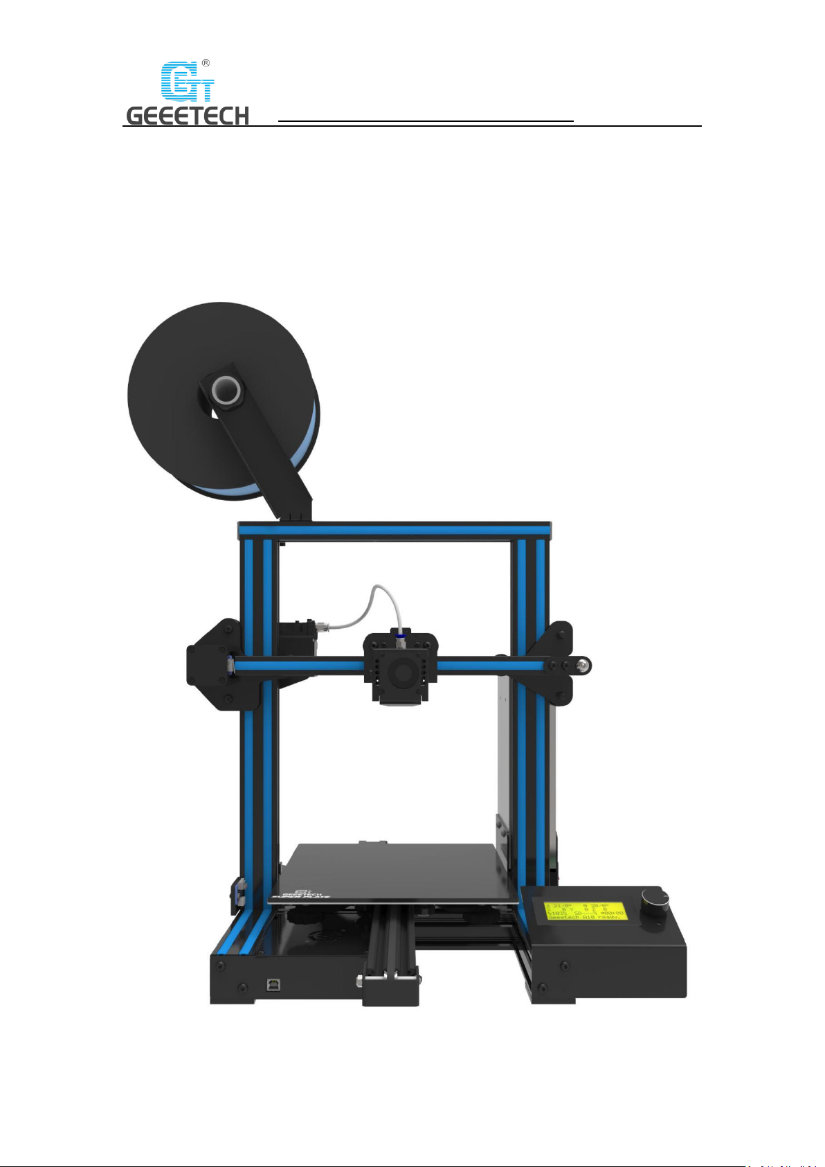
2 Printer display
(Picture 2-1)
5
SHENZHEN GETECH TECHNOLOGY CO., LTD
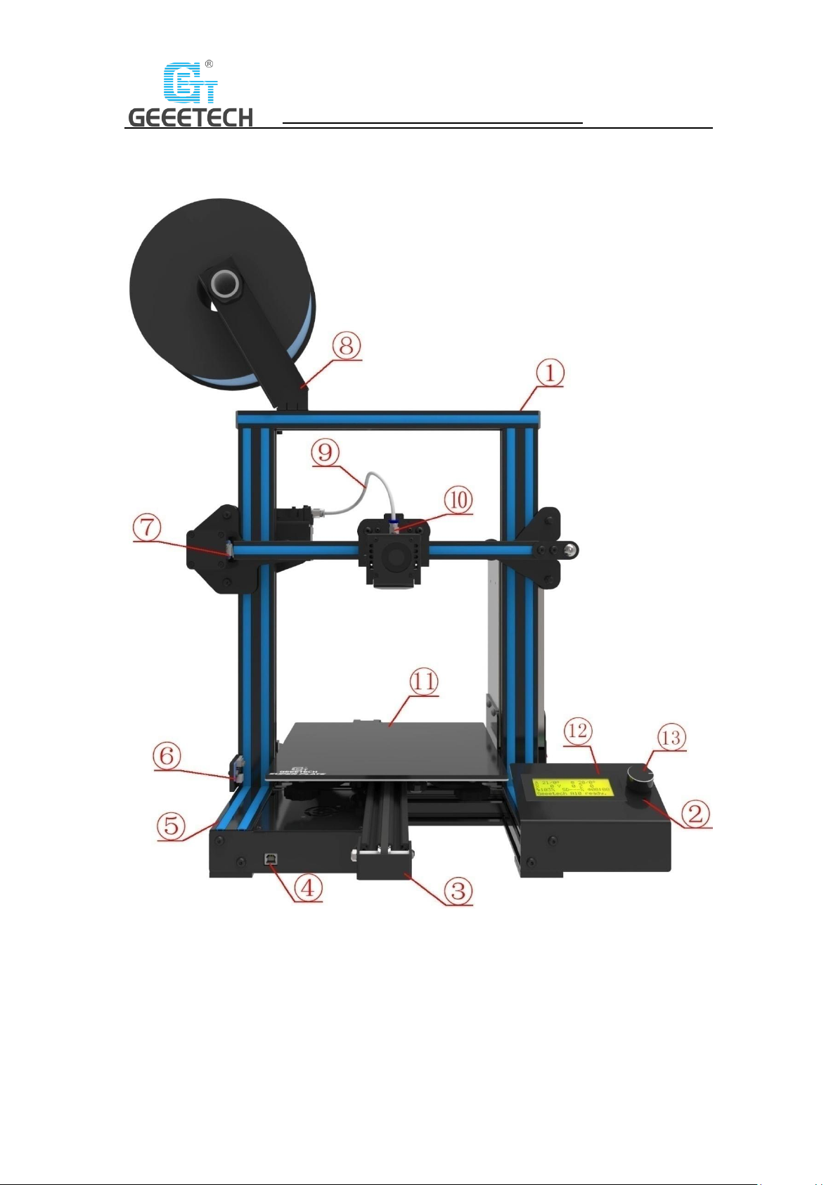
(Picture 2-2)

6
SHENZHEN GETECH TECHNOLOGY CO., LTD
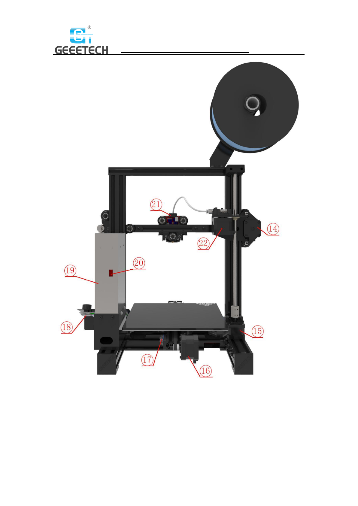
(Picture 2-3)
1. Gantry frame
2. Reset button
3. Y axis
4. USB port
5. Pedestal
6. Z axis end stop
7. X axis end stop
8. Filament spool holder kit
9. Teflon tube
10. Extruder head kit
11. Hot bed
12. LCD2004 screen
13. Knob
14. X axis motor
15. Z axis motor
16. Y axis motor
17. Y axis end stop
18. SD card slot
19. PSU kit
20. PSU switch
21. Extruder wire connector
22. Extruder kit
23. Power switch
7
SHENZHEN GETECH TECHNOLOGY CO., LTD
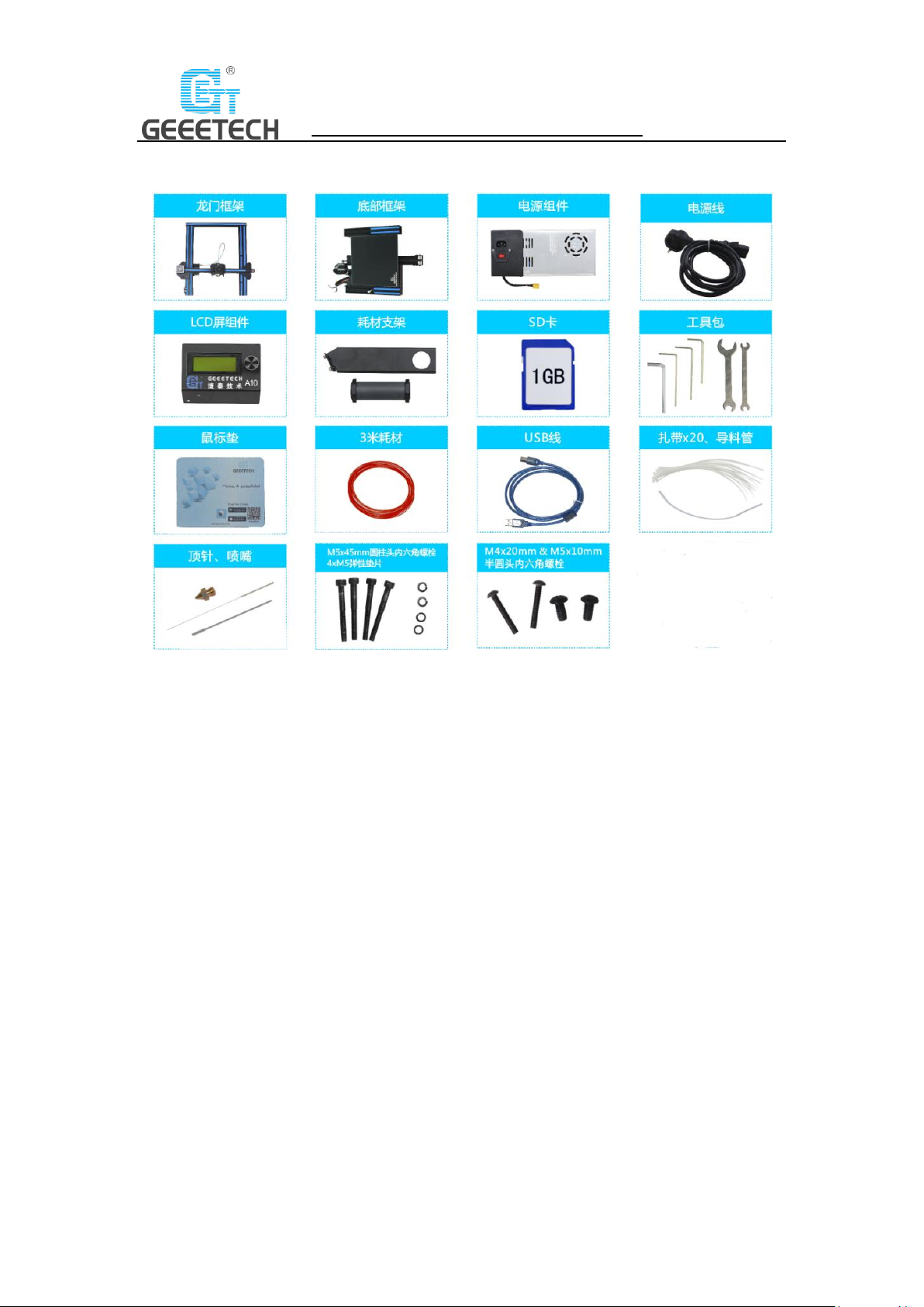
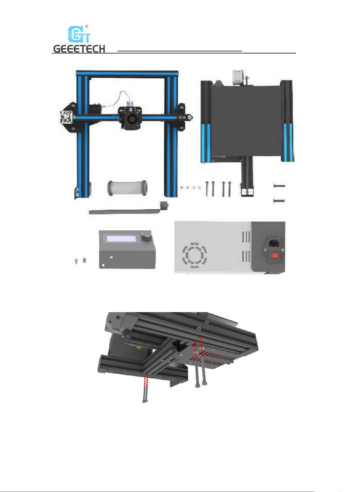
Please check the accessories first when you’ve received the printer (Refer to picture 2-4). If
missing any spare part, please contact your sales timely.
(Picture 2-4)
3 Assembling
3.1 Assembling the main frame
The main frame consists of the gantry frame and the pedestal, PSU kit, LCD kit, spool holder kit,
and their supporting screws. See picture (3-1).
8
SHENZHEN GETECH TECHNOLOGY CO., LTD
(Picture 3-1)
1) Assemble the gantry frame and pedestal from bottom to top with 4 M5x45 screws and 4 M5
spring washers. See picture (3-2).
(Picture 3-2)
9
SHENZHEN GETECH TECHNOLOGY CO., LTD
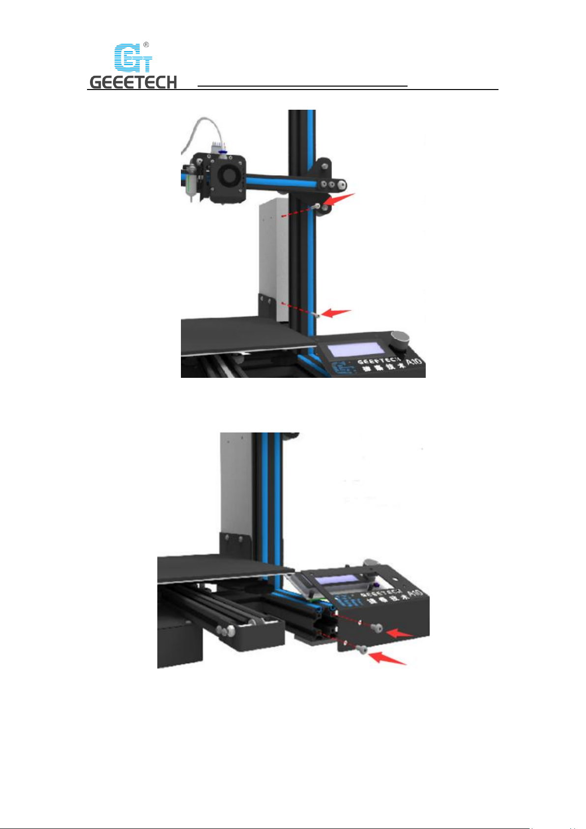
2) Fix the PSU kit to the gantry frame with 2 M4x20 screws. See picture (3-3).
(Picture 3-3)
3) Fix the LCD kit to the correct holes on the right side of the pedestal with 2 M5x10 screws.
See picture (3-4).
(Picture3-4)

10
SHENZHEN GETECH TECHNOLOGY CO., LTD
4) Fix the spool holder to the top gantry with 2 M3x6 and 2 M3 T-shape nuts. Details see
picture (3-5).
(Picture 3-5)
3.2 Wire connection
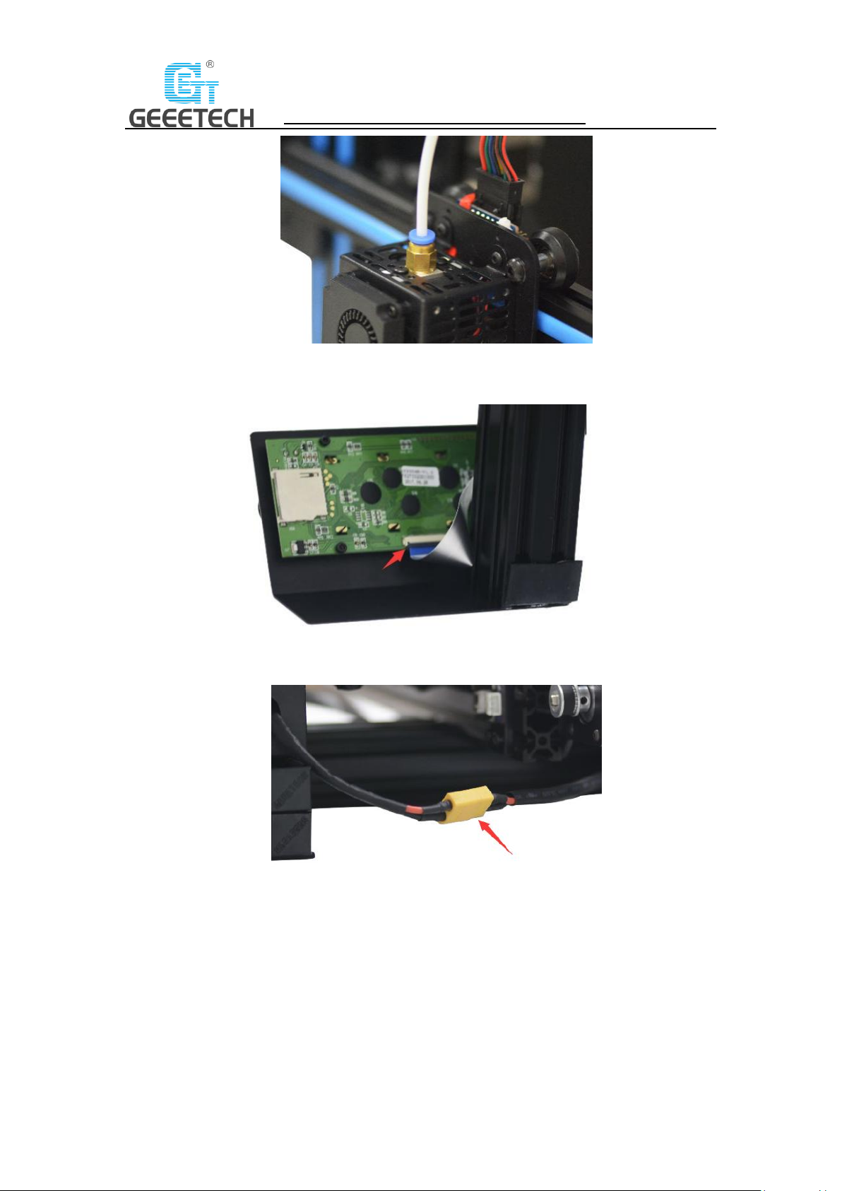
1) The teflon tube is connected to the quick-insert connector of the extruder and the extruder
head. Be sure the Teflon is inserted into the very bottom or it may cause clog. Details see
picture (3-6, 3-7).
(Picture 3-6)
11
SHENZHEN GETECH TECHNOLOGY CO., LTD
(Picture 3-7)
2) Insert the flat ribbon of the LCD into the socket behind the LCD screen. See picture (3-8)
(Picture 3-8)
3) Connect the PSU cable. See picture (3-9)
(Picture 3-9)
4) Plug the extruder cables into the socket of the extruder head extension board as firmly as
possible. See picture (3-10)

12
SHENZHEN GETECH TECHNOLOGY CO., LTD
(Picture 3-10)
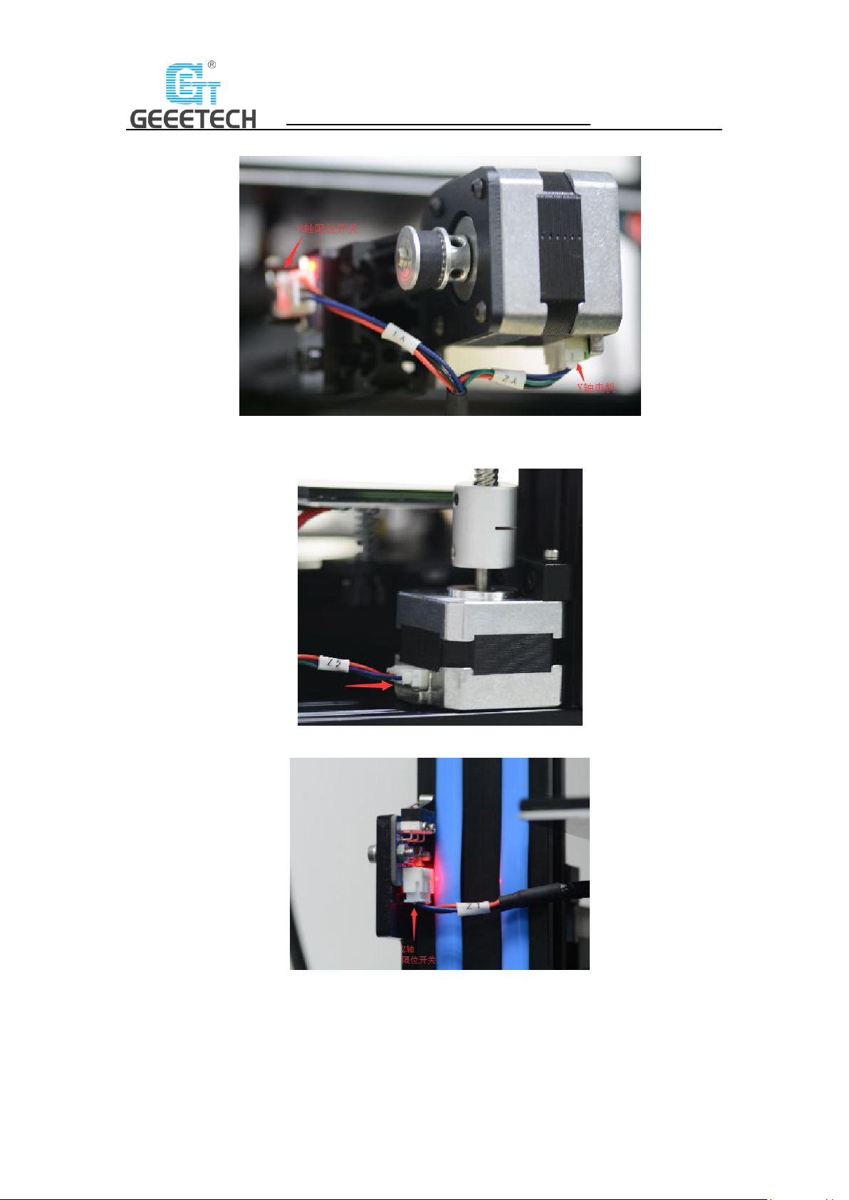
5) Connect the extruder motor wires. See picture (3-11).
(Picture 3-11)
6) Connect the wires of X axis’ motor and end stop. See picture (3-12).
(Picture 3-12)
13
SHENZHEN GETECH TECHNOLOGY CO., LTD
7) Connect the wires of Y axis’ motor and end stop. See picture (3-13).
(Picture 3-13)
8) Connect the wires of Z axis’ motor and end stop. See picture (3-14, 3-15).
(Picture 3-14)
(Picture 3-15)
14
SHENZHEN GETECH TECHNOLOGY CO., LTD
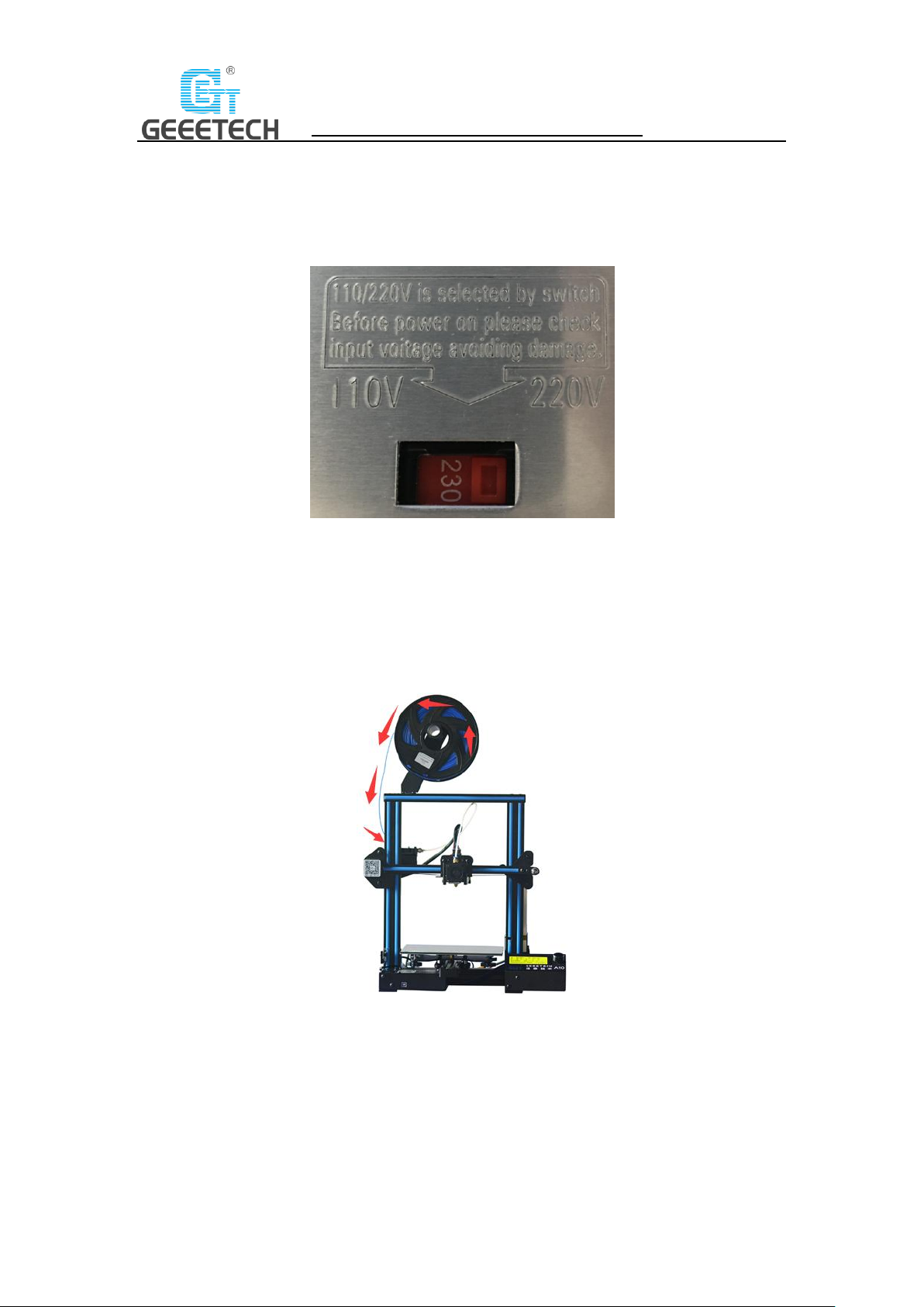
3.3 Check the power input mode.
Choose the correct voltage according to your local standard requirement. See picture (3-16)
(Be sure the voltage is switched to the correct one. We provide 220V and 110V for option.)
(Picture 3-16)
3.4 Check the filament
Put the filament on the spool holder. Please pay attention to the feeding direction of the filament.
See picture (3-17).
(Picture 3-17)
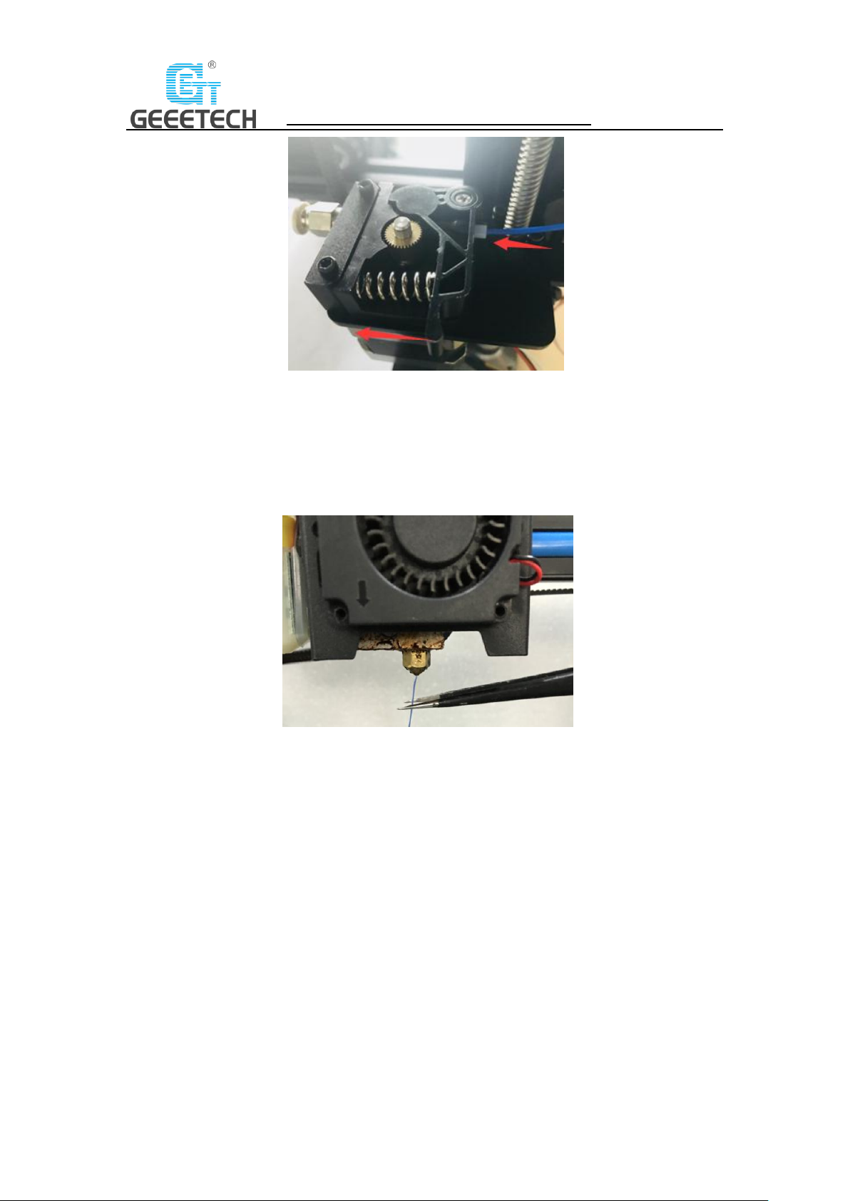
Since the filament is bent, the first section of it needs to be straightened by hand and sharpened
with scissors to make it easier to insert the filament into the bottom of the extrusion head. Press
down the lever handle of the extruder and insert the filament into the feeding tube until it
reaches the extruder head. See picture (3-18).
15
SHENZHEN GETECH TECHNOLOGY CO., LTD
(Picture 3-18)
When print PLA, set the target nozzle temperature about 180-210℃. When the temp is stable,
control the extruder filament feeding on LCD screen (“Move axis”), extruder will automatically
feed until there is molten material flowing from the nozzle.
Observe the nozzle, if there is no obvious stuck and the filament is out smoothly, then stop
filament feeding, clear the nozzle with tweezers. See picture (3-19).
(Picture 3-19)
4 First print
4.1 Level the print platform
The first layer is the key to the quality of the print model. The factory default setting is a little
high in order to avoid scratching the hotbed and nozzle, so users need to adjust the distance
between nozzle and hotbed again. After the first-time bed leveling finished, users don’t need to
level the bed in future printing.
1) Rough leveling
Home the printer first (Prepare> Auto home), then it shows the option “Level corners” on the
LCD screen. Put a piece of A4 paper on the platform, click “Next corner”, the extruder head
moves counterclockwise from the bottom left corner to the four corners of the platform. See
picture (4-1).
 Loading...