

Page 1
Assembly Instructions of Geeetech Prusa I3 A pro
(Version 04-11-2016)
Page 2

CONTENT
Safety Instructions ............................................................................................................................ 3
Preparation ........................................................................................................................................ 4
1. Unfold the box and check the package.......................................................................................... 1
2. Assemble Y axis ............................................................................................................................ 1
3. Build the printing platform ......................................................................................................... 11
4. Assemble Y smooth rods ............................................................................................................. 12
5. Mount the Y-axis belt .................................................................................................................. 13
6. Assemble the Z-axis stepper motor, bottom mount and couplings.............................................. 13
7. Assemble Y - Z axis .................................................................................................................... 16
8. Attach the heated bed. ................................................................................................................. 17
9. Mount the extension board .......................................................................................................... 18
10. Assemble the left end of the X axis(motor end) ..................................................................... 19
11. Assemble the right end of the X axis. (X idler end) .................................................................. 26
12. Assembly of the extruder carriage ............................................................................................. 28
13. Assemble the X&Z axis ............................................................................................................ 30
14. Assemble the Z axis top mount ................................................................................................. 32
15. X belt driving wheel .................................................................................................................. 33
16. Add the belt ............................................................................................................................... 37
17. Mount the extruder .................................................................................................................... 39
18. Mount the endstop of Y and Z axis ........................................................................................... 40
19. Wiring ....................................................................................................................................... 42
20. Mount the filament spool. ......................................................................................................... 49
21. Arrange the wires and tidy them up with the coil. .................................................................... 51
22. Tips ............................................................................................................................................ 51
Page 3

Safety Instructions
Building the printer will require a certain amount of physical dexterity, common
sense and a thorough understanding of what you are doing. We have provided this
detailed instruction to help you assemble it easily.
However ultimately we cannot be responsible for your health and safety whilst
building or operating the printer, with that in mind be sure you are confident with
what you are doing prior to commencing with building or buying. Read the entire
manual to enable you to make an informed decision.
Building and operating involves electricity, so all necessary precautions should
be taken and adhered to, the printer runs on 12V supplied by a certified power supply,
so you shouldn’t ever have to get involved with anything over 12V but bear in mind
there can still be high currents involved and even at 12V they shouldn’t be taken
lightly.
High temperatures are involved with 3D Printing, the Extrusion nozzle of the hot
end can run about 230°C, the heated bed runs 110°C and the molten plastic extruded
will initially be at around 200°C, so special care and attention should be made when
handling these parts of the printer during operation.
We wouldn’t recommend leaving your printer running unattended, or at least
until you are confident to do so. We cannot be held responsible for any loss, damage,
threat, hurt or other negligent result from either building or using the printer.
Page 4

Preparation
1. Unpack the kit and check if all parts are in the box and check the condition of each
part, there might be some damage during shipping. To help you with this, there is
BOM in the box and each bag was labeled with part number.
2. Contact our customer service immediately by email or through the website if you
find any missing or damaged parts. And on the bottom of the BOM, there is a
signature of reviewer, please take a picture of it and attach the picture in your mail.
3. Read through each chapter of these instructions to gain an over-all idea of what is
involved and how long it might take, before starting on the work described.
4. Before you start, you can put all the part in order to save your time especially those
screws and nuts. Do not mix them up.
5. Ensure you have the necessary skills to carry out the work, or enlist the help of
someone who does.
6. Work on a big firm table or bench in a clean dry well-lit area.
7. This kit contains tiny parts; please keep them away from kids under 3.
8. Ask for help if you run into any problems - our contact details are on the website
and we will always do our best to resolve any problems encountered.
Page 5
Shenzhen GETECH CO.,LTD
GEEETECH
1
1. Unfold the box and check the package
Unfold the package and take all the parts out to check the condition of the items. As
you can see, all the parts are packed very carefully.
Tips:
1. Before assembly, you are advised to put all the parts, especially the screws and nuts
in order, which will save you a lot of time looking for the required parts.
2. The part ID is corresponding to the number labeled on the bag of every part.Some
parts may not have label, you can refer to the pictures on the package list.
For step by step video instruction, please refer to the video. (Some require parts used in
the video may differ from this instruction; please refer to this manual as a priority)
2. Assemble Y axis
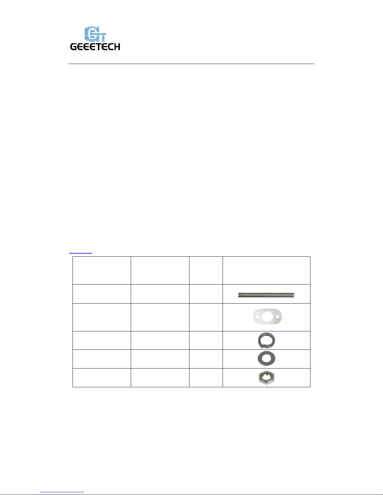
2.1Assemble the 2 threaded rods.
VIDEO
Pic
Part ID
Required
number
Required parts
NO.5
2
Y threaded rod
NO.A10
2
connecting plate
NO.10
6
Spring washer
NO.9
8
M10 washer
NO.13 8 M10 nut
Thread the nuts and washers into the two M10 threaded rods separately. The orders
should be:
Page 6

Shenzhen GETECH CO.,LTD
GEEETECH
2
Page 7
Shenzhen GETECH CO.,LTD
GEEETECH
3
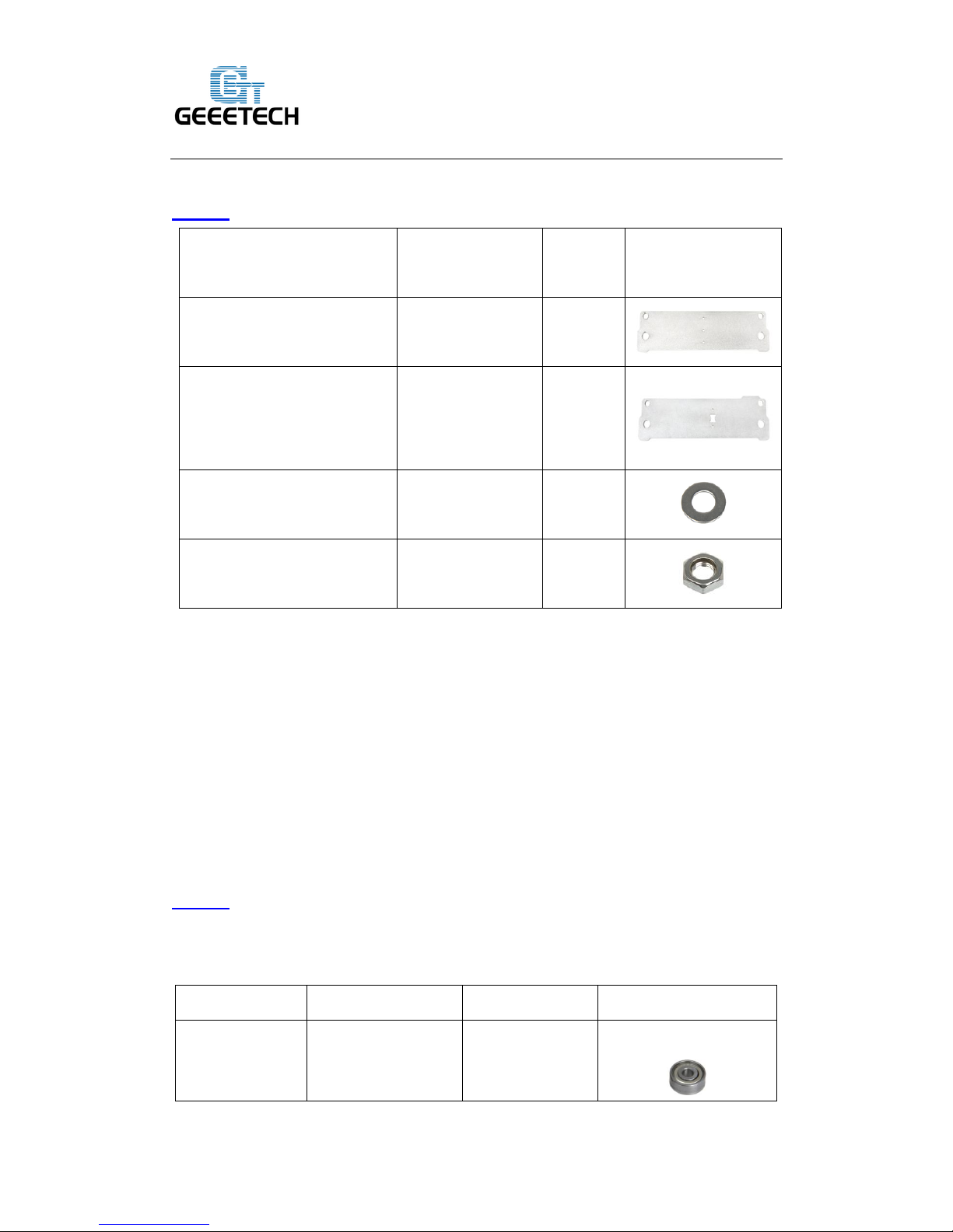
2.2Attach the front and rear side support plates of the rods.
VIDEO
Slide assembled threaded rods into the support plates. Screw up the rods and plates
with 4 M10 nuts and M10 washers.
* Tips: The Y-axis must be a rectangle, that is the rods on both side should be parallel,
so is the front and rear plate. Otherwise it will cause obstruction for the belt later.
2.3Assemble the Y idler
VIDEO
Note: as the driving wheel was added later, so in the video, there is some difference from what you
get. But do not worry; it won’t affect the whole process.
Pic
Part ID
Required number
Required parts
NO.36 2
Ball bearing
Pic
Part ID
Required
number
Required parts
NO. A2 1
Front Side Support
NO.A3
1
Rear Side Support
NO.9 4 M10 washer
NO.13 4 M10 nut
Page 8
Shenzhen GETECH CO.,LTD
GEEETECH
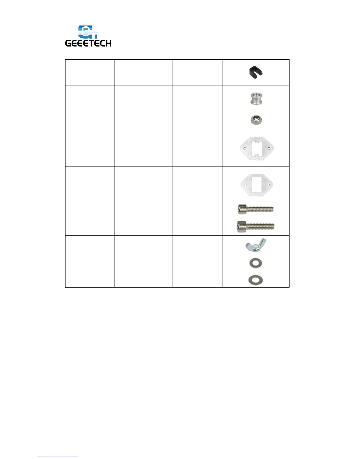
4
NO.37 1
bearing holder
NO.38
1
Driving wheel
NO.14
1
M4 lock nut
NO.A8 1
Guide Block
A
NO.A9
1
Guide Block
B
NO.24
3
M3 x 25screw
NO.28
1
M4x25 screw
NO.15
1
M3 wing nut
NO.7
3
M3 washer
NO.8
2
M4 washer
Step1. Amount guide block A and B onto the front support plate together, screw up it
with 2 M3x25 screws and M3washers.
Page 9
Shenzhen GETECH CO.,LTD
GEEETECH
5
Page 10
Shenzhen GETECH CO.,LTD
GEEETECH
6
Note: the guide block B is close to front support plate.
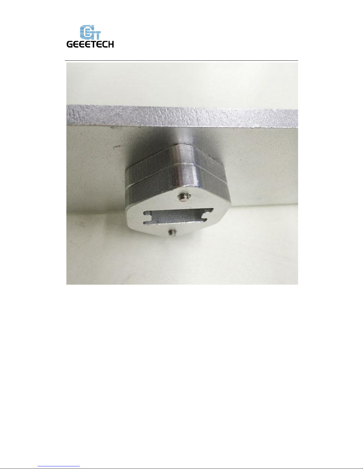
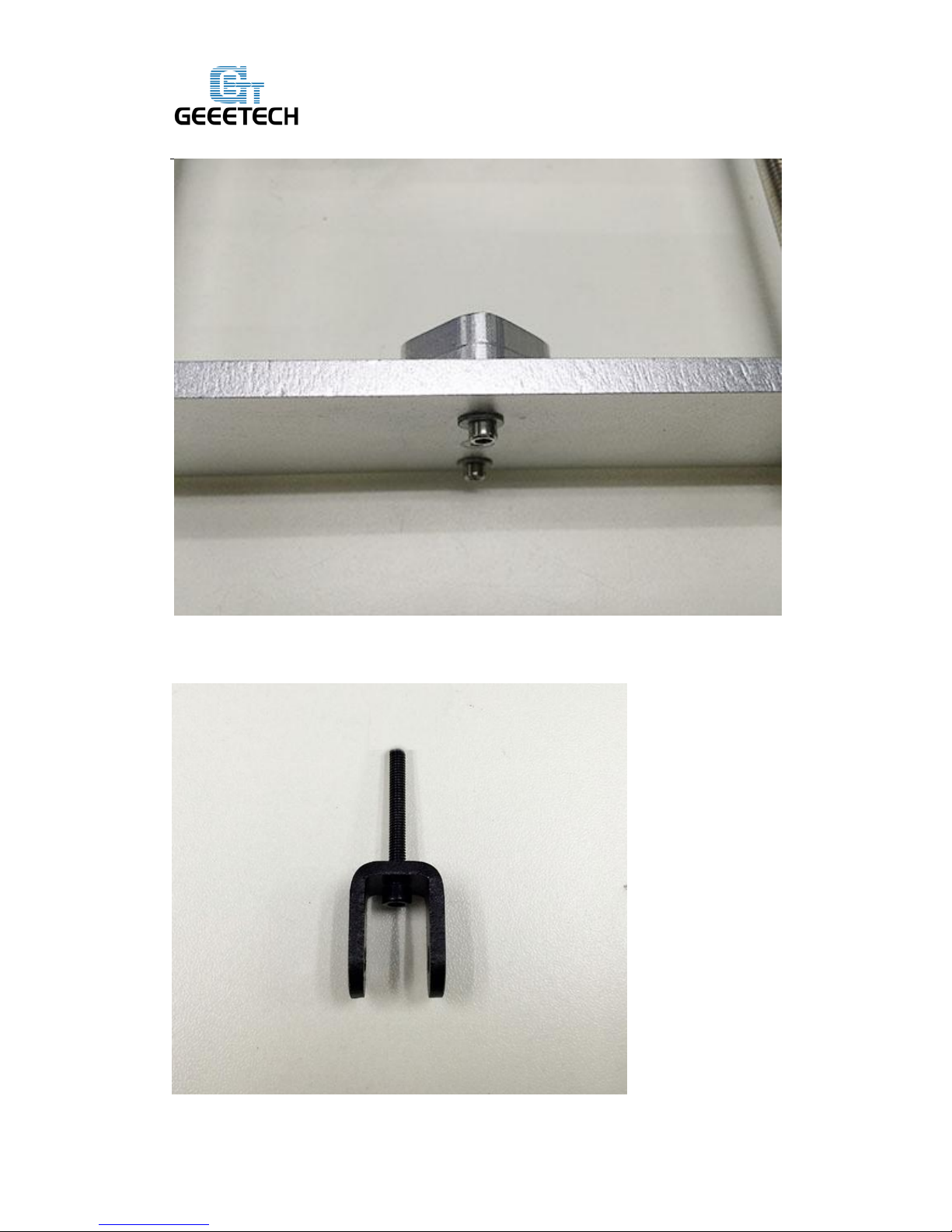
Step2. Thread a M3 x25screw and M3washer through the bearing holder.
Page 11
Shenzhen GETECH CO.,LTD
GEEETECH
7
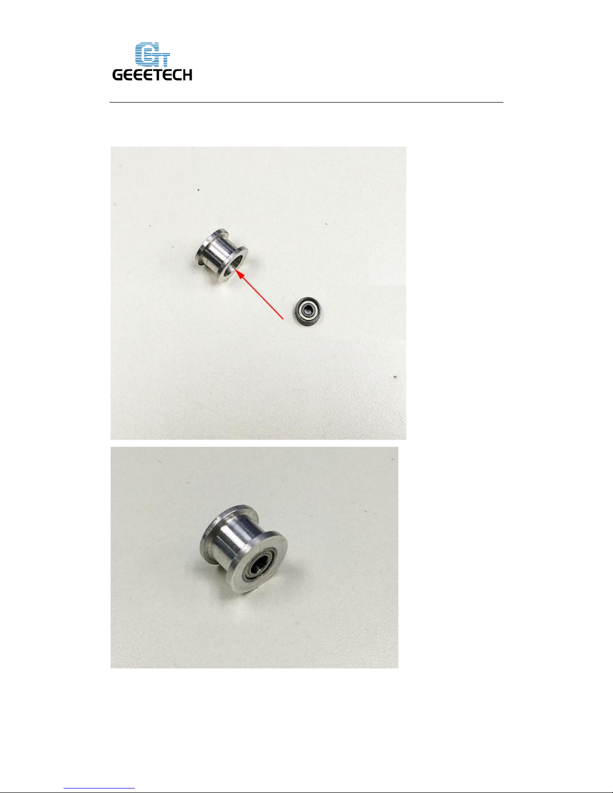
Step3. Insert the two MR84zz ball bearings into both ends of the driving wheel. You
will need use some force to do this.
Page 12
Shenzhen GETECH CO.,LTD
GEEETECH
8
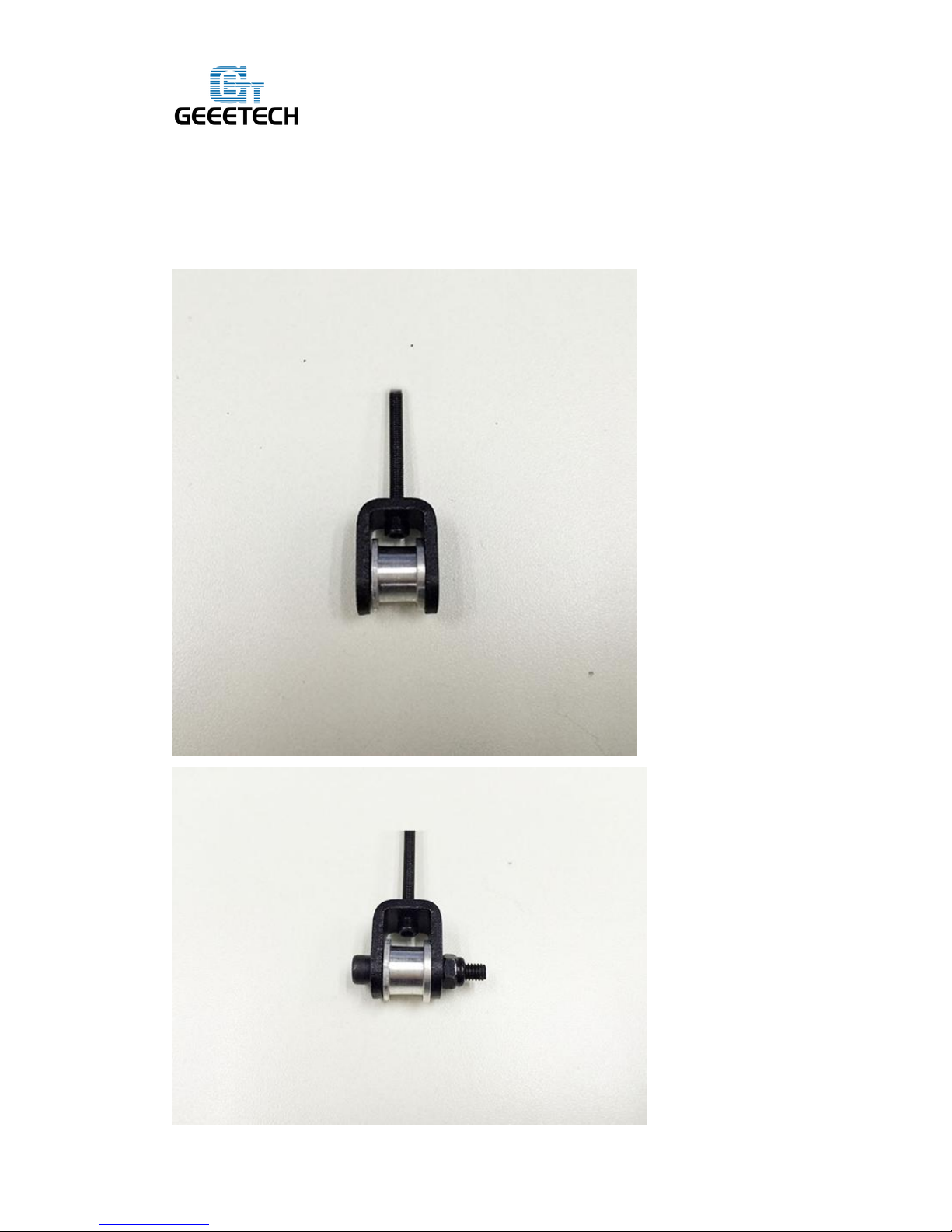
Step4. Put the M4 x25 screw and M4 washer through the driving wheel. Lock the
other end with a M4 lock nut. You may need a wrench to tighten locking nut. If the
holder is too tight, you need to open it a bit.
Page 13
Shenzhen GETECH CO.,LTD
GEEETECH
9
*Do not screw it too tight, you should leave enough room for the wheel to turn freely.
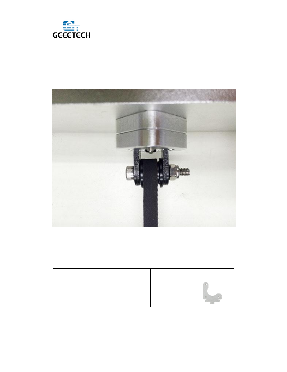
Step5. Mount the assembled bearing holder through the guide blocks onto the front
support plates. And screw it with a wing nut. (You can also mount it later when
assembling the belt)
*Please leave enough room for the belt between the ball bearing and the screw.
2.4Mount the Y motor
VIDEO
Pic
Part ID
Required number
Required parts
NO. A7 1
Y motor fixed plate
Page 14
Shenzhen GETECH CO.,LTD
GEEETECH
10
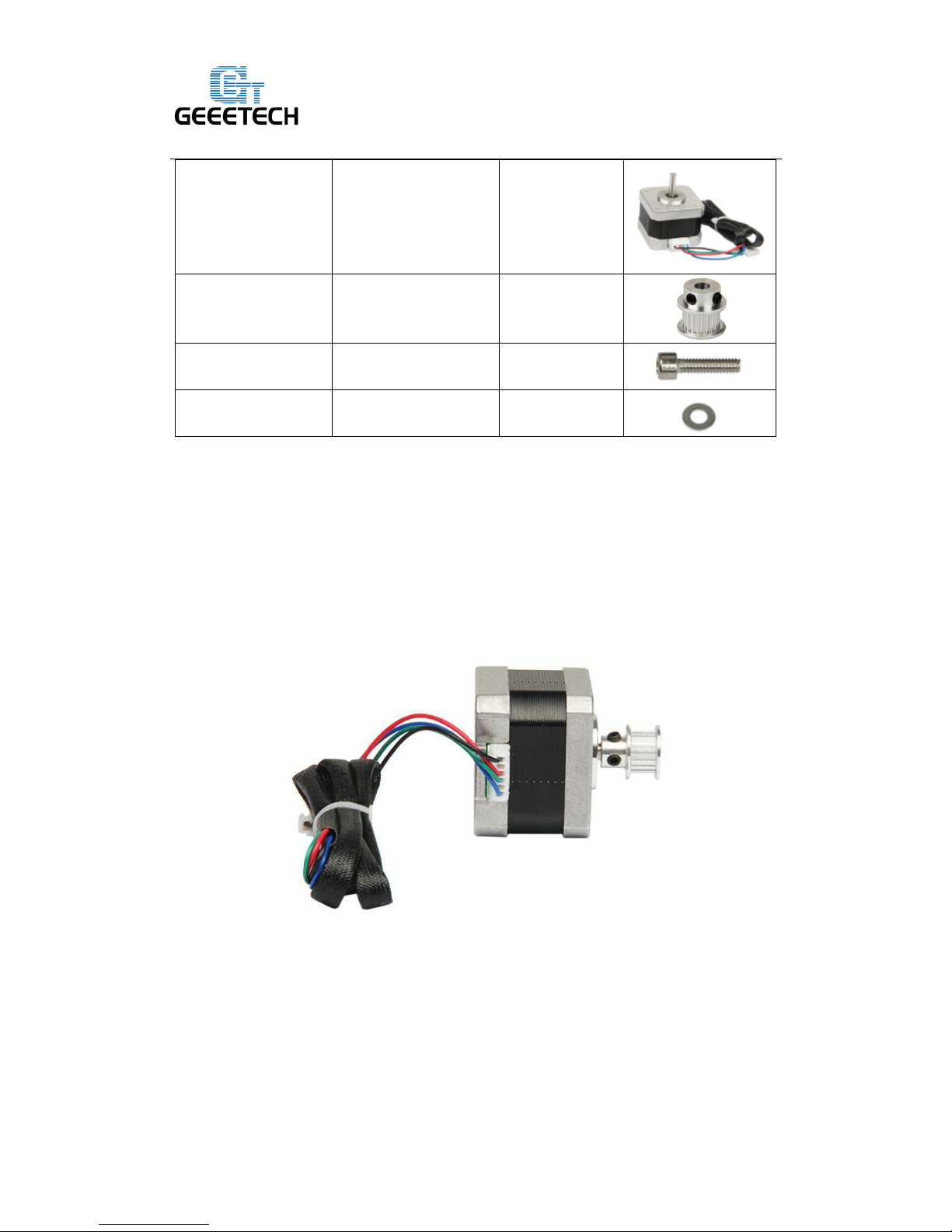
NO.54 1
Stepper motor
NO.41 1
pulley
NO.21
5
M3 x 10screw
NO.7
5
M3 washer
The pulley is changed but it will not affect the assembly and use. So some picture is
not updated.
Step1. Mount the pulley on the motor shaft, one of the screws should be screwed on
the cross section of the shaft. Screw it up tightly.
Step2. Insert the motor block into the slot; you may need to use a little strength to do
this. Then screw the motor on the Y motor fix plate with 3 M3 x 10 screws and
M3washers
Step3. Fix the block plate with 2 M3 x 10 screws and M3 washers.
Page 15
Shenzhen GETECH CO.,LTD
GEEETECH
11
(In the video, I use the M3x16mm screw at this step; you can use either of them)
3. Build the printing platform
VIDEO
Pic
Part ID
Required
number
Required parts
NO.A6
1
Y building
platform
NO.39
1
Y belt mount
Page 16
Shenzhen GETECH CO.,LTD
GEEETECH
12
NO.33
4
PCS8UU linear
bearing
NO.21
2
M3 x 10 screw
NO.27
16
M4x12 screw
NO.7
18
M3washer
NO.8
16
M4 washer
NO.12
16
M4 hex nut
Step1. Mount the belt mount at the middle of the platform with 2 M3 x 10 screws and
M3washers.
Step2. Mount the 4 PCS8UU linear bearing on the platform with 16 M4x12 screws
and M4 hex nut on the same side with the beltmount.
*In the video, I used the SCS8UU, but now we have updated the SCS8UU into PCS8UU to
lighten the load of the building platform, so the assembly will be a bit different, you need to use
hex nut to fix the bearing.
4. Assemble Y smooth rods
VIDEO
Pic
Part ID
Required number
Required parts
NO.3
2
Y smooth rod
NO.30
4
Lock screw
M3x4 mm
Thread two smooth rods through: front side support [A2]> linear bearings > rear side
support [A3] respectively. And fix the smooth rods with 4 lock screws.
Page 17
Shenzhen GETECH CO.,LTD
GEEETECH
13
*When threading the rod, please make sure the holes are aligned and do not force it,
or you will break the balls in the bearings.
5. Mount the Y-axis belt
VIDEO
Pic
Part ID
Required number
Required parts
NO.42 1
Timing belt
NO.20
2
M3 x 8 screw
NO.7
2
M3 washer
Step1. Punch a hole on one end of the belt(the hole can be as the diameter of the M3
screw, leave enough margin )
Step2. Fix the belt on one side of the belt -mount with a M3 x 8 screw and washer.
Step3. Guide the belt around the pulley on the motor and the Y idler.
Step4. Punch a hole on the other end of the belt and fix it on the belt -mount with a
M3 x 8 screw and M3 washer.
*Tips:
1.Before you drill your second hole, make sure to pull belt tightly to make sure to find
proper placement of hole for a tight belt, if it is too loose, it will hinder the move of t
he print platform.
2. Loosen the Y idler wing nut when tightening belt onto the Y belt mount, in order to
make securing the belt to the block easier. Be sure to tighten wing nut fully once done.
6. Assemble the Z-axis stepper motor, bottom mount and couplings
Page 18

Shenzhen GETECH CO.,LTD
GEEETECH
14
VIDEO
Pic
Part ID
Required number
Required parts
NO.A1
1
X-Z frame
NO. A4 2
Z Motor fixed plate
NO.54
2
Stepper Motor
NO.40
2
Coupling
NO.22
4
M3 x 16screw
NO.21
8
M3x10 screw
NO.7
12
M3 washer
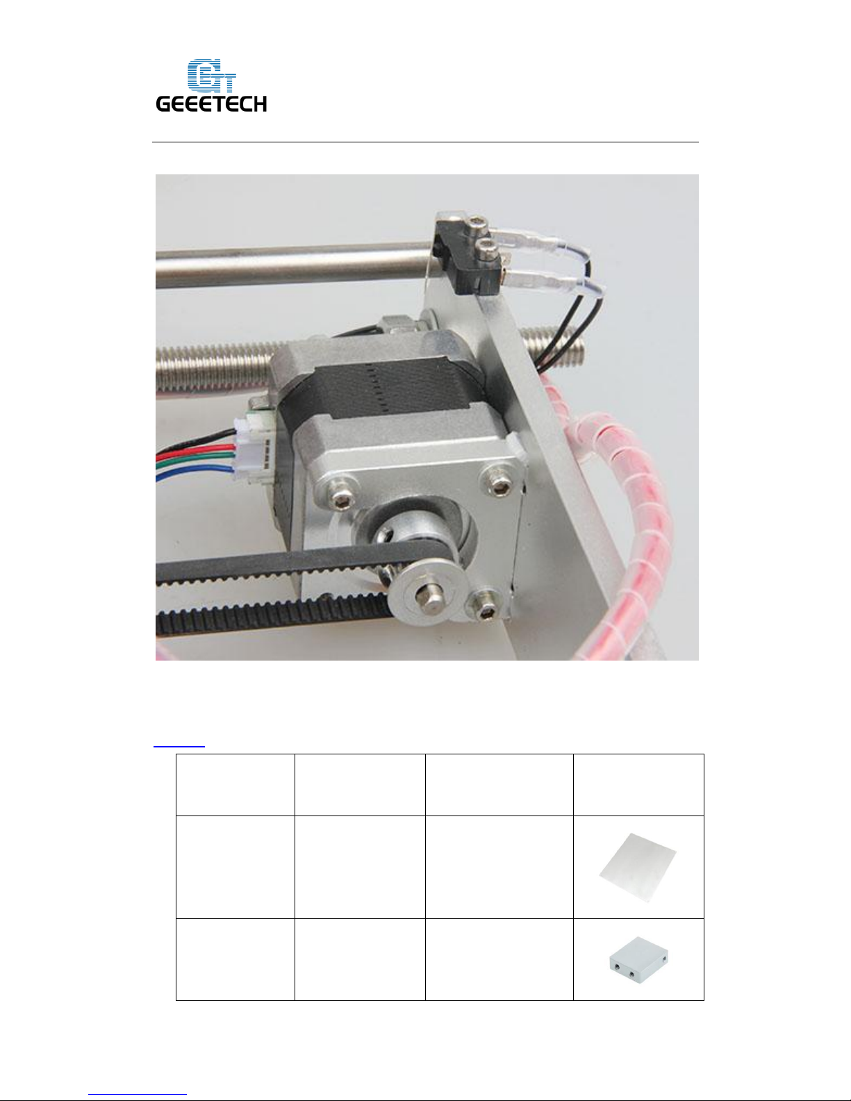
Step1. Mount the motor on Z Motor fixed plate, screw it with 4 M3x10screws and M3
washers.
Step2. Thread the wires of the motors through the hole at the bottom of the X-Z frame.
Mount the assembled motor to the X-Z frame (A1), and screw the X-Z frame and the
Z Motor fixed platewith 4 M3 x 16screws and M3washers.
Page 19

Shenzhen GETECH CO.,LTD
GEEETECH
15
Step3. Mount the coupling on the motor shaft, one of the screws should be screwed on
the flat side of the shaft (As the picture shows). Screw it as tightly as possible.
Page 20

Shenzhen GETECH CO.,LTD
GEEETECH
16
Step4. Repeat the above steps for another Z axis motor.
7. Assemble Y - Z axis
VIDEO
Pic
Part ID
Required number
Required parts
NO.22
4
M3 x 16 screw
NO.7
4
M3 washer
Step1. Held upright the X-Z frame on the threaded rods (Right after the Y connecting
plate)
Step2. Screw up the main frame to the Y connecting plate with 4 M3 x16 screws and
M3 washers.
Page 21

Shenzhen GETECH CO.,LTD
GEEETECH
17
8. Attach the heated bed.
VIDEO
Pic
Part ID
Required number
Required parts
NO.49
1
Heat bed
NO.32 4 Spring
NO.7
4
M3 washer
NO.29
4
Hex Counter-
sunk-head screw
Mount the heat bed on the platform with 4 M3 x30Hex Counter-Sunk-head screw and
wing nuts with springs in between.
Page 22

Shenzhen GETECH CO.,LTD
GEEETECH
18
*Note:
The heating wire is pre-soldered on the bed and the thermometry wire is attached on
the bed. The soldered side is better to be attached downwards.
9. Mount the extension board
VIDEO
Pic
Part ID
Required number
Required parts
1
Extension board
NO.21
3
M3 x 10screw
NO.44 3 Spacer
Page 23

Shenzhen GETECH CO.,LTD
GEEETECH
19
Step1. Insert the spacer into the hole on the extension board from back to front.
Step2. Fix the spacer on the left back side of X-Z frame with 3 M3x10screws.
10. Assemble the left end of the X axis(motor end)
VIDEO
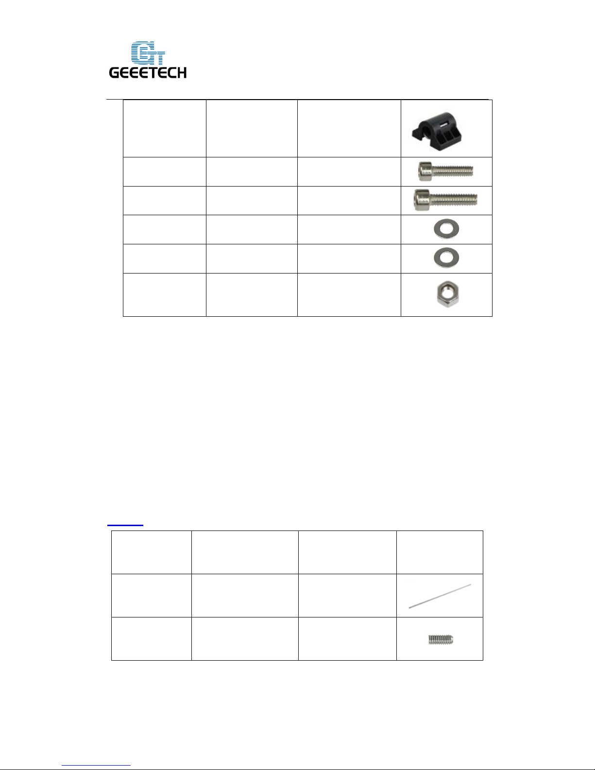
10. 1. Mount the Z-axis nut, linear bearing
Part name
Part ID
Required number
pic
Z-axis nut
No.16
1
Page 24

Shenzhen GETECH CO.,LTD
GEEETECH
20
X-axis motor end
No.M1 1
Linear Bearing
LMH8LUU
No. 35 1
M3 x 45 screw
No.25
1
M3 x 6mm screw
No. 19
8
M3 washer
No. 7
2
\
Spring
No. 32
1
Step1. Mount the Z nut on the X-axis left end from bottom to up, fix with M3 x 6mm
screws.
Step2. Mount the linear bearing on X-axis motor end from bottom to up. Fix it up
with M3 x 6mm screws.
10.2 Mount the endstop trigger
1. Thread a M3 washer> spring>M3 washer in order to the M3x45mm screw.
2. Thread half of the M3x50mm screw into the screw hole.
Page 25

Shenzhen GETECH CO.,LTD
GEEETECH
21
If there is no enough room for both the Z nut and the linear bearing, you can move the
Z nut upwards, as shown in the following picture:
Page 26

Shenzhen GETECH CO.,LTD
GEEETECH
22
10. 3 mount the X motor.
Part name
Part ID
Required number
pic
M3 x 6 mm screw
No. 19
3
Stepper motor
No.54
1
Pulley
No.41
1
Step1. Mount the pulley on the motor shaft. Screw it on the flat side.
Page 27

Shenzhen GETECH CO.,LTD
GEEETECH
23
Step 2.Mount the stepper motor on the motor end with 3 M3 x 6 mm screw.
Page 28

Shenzhen GETECH CO.,LTD
GEEETECH
24
10.4 Mount the endstop
Part name
Part ID
Required number
pic
M2.5 x 8 mm
screw
No. 17
2
End stop
No.46
1
Mount the endstop on the top of X-axis motor end with 2 M2.5 x 8mm screws
Page 29

Shenzhen GETECH CO.,LTD
GEEETECH
25
Page 30

Shenzhen GETECH CO.,LTD
GEEETECH
26
11. Assemble the right end of the X axis. (X idler end)
VIDEO
Part name
Part ID
Required number
pic
Z-axis nut
No.15
1
X-axis idle end
No.M2
1
Linear Bearing
LMH8LUU
No. 35
1
M3 x 6mm screw
No.18
8
Step1.Mount the Z axis nut on the bottom of X-axis right end with 4 M3 x6mm
screws.
Step2. Mount the linear bearing on X-axis motor end from bottom to up. Fix it up
with M3 x 6mm screws
Page 31

Shenzhen GETECH CO.,LTD
GEEETECH
27
Page 32

Shenzhen GETECH CO.,LTD
GEEETECH
28
12. Assembly of the extruder carriage
VIDEO
Part name
Part ID
Required number
pic
X
Carriage
No.M3 1
Bearing Bracket
No.M4
4
Extruder holder
No.M5 1
Linear Bearing
LM8LUU
No.34 2
Belt bracket
No.43 1
M3x6mm screw
No. 18
8
M3x10mm screw
No. 20
2
M4x6mm screw
No. 27
2
M3 nut
No.11
2
Step1. Fix the 4 Bearing Brackets on the back of the X Carriage loosely with
M3x6mm screws. Insert the linear bearing into the slot and screw the bracket tightly.
Page 33

Shenzhen GETECH CO.,LTD
GEEETECH
29
Please notice the front and back of the plate.
Step2.fix the belt mounts on the back of the carriage with 2 M3x 10mm screws and
M3 hex nuts.
Step3. Fix the extruder holder on the front side of the X carriage using M4x6mm
screws.
Page 34

Shenzhen GETECH CO.,LTD
GEEETECH
30
13. Assemble the X&Z axis
VIDEO
Part name
Part ID
Required number
pic
L300mm lead
screw
No.4
2
L320mm smooth
rod
No.1
2
L390 mm smooth
rod
No.2
2
locking ring
No.31
4
Page 35

Shenzhen GETECH CO.,LTD
GEEETECH
31
Step1. Thread the lead screw to the nut of both end of X axis.
Keep both end of X axis at the same place of the rod, you are advised to measure the
distance of the both side so that they are at the same level when you put them up.
Step2. Plug the lead screw on the X motor end to the left coupling on the left bottom
of the Z axis. Then thread the 320mm smooth rod into the linear bearing.
Step3. Thread the L390mm smooth rod into the X motor end >> thread the extruder
carriage on the two rods
Step4. Thread the two X axis smooth rods into the hole of X idler end.
Step5. Plug the vertical lead screw into the coupling on the right bottom of the Z axis.
Then thread the 320mm smooth rod into the linear bearing.
Step6. Thread 4 locking rings on the 2 rods separately. Screw up the 4 locking rings.
Note: the smooth rods and the lead screw of Z axis are vertical and the X axis is
Page 36

Shenzhen GETECH CO.,LTD
GEEETECH
32
horizontal, which is very important, or it will hinder the move of the Z axis.
(This main frame is a bit different from yours but it won’t affect your assembly)
14. Assemble the Z axis top mount
Part name
Part ID
Required number
pic
Z top mount
No.A6
2
M3 x 16mm screw
No.21
4
Page 37

Shenzhen GETECH CO.,LTD
GEEETECH
33
Lock screw
No.30
4
Step1. Add the Z top mount (No.A6) to the top of A1. Slowly rotate the rods into the
holes.
Step2. Screw it up with M3 x 16mm screw.
Step3. Use the lock screw to fix thesmooth rodson both top and bottom.
15. X belt driving wheel
Part name
Part ID
Required number
pic
Driven wheel
holder
No.37
1
Driven wheel
No.38
1
MR84zz Ball
Bearing
No.36
2
Page 38

Shenzhen GETECH CO.,LTD
GEEETECH
34
M3 x45mm screw
No.25
1
M4 x 25mm screw
No.29
1
M4 lock nut
No.13
1
wing nut
No.14
1
Step1. Thread the M3 x 45 screw into the top of the Driven wheel holder.
Step2. Insert the two MR84zz ball bearingsinto both ends of the driving wheel.
Page 39

Shenzhen GETECH CO.,LTD
GEEETECH
35
Page 40

Shenzhen GETECH CO.,LTD
GEEETECH
36
Step3. Put the M4 x25 screw and M4 washerthrough the driving wheel. Lock the
other end with a M4 lock nut. You may need a wrench to tighten locking nut.
*Do not screw it too tight, you should leave enough room for the wheel to turn freely.
Page 41

Shenzhen GETECH CO.,LTD
GEEETECH
37
16. Add the belt
VIDEO
Part name
Part ID
Required number
pic
Timing belt
No.42
1
Belt bracket
No.43 1
Step1. Insert one end of the belt in the groove. Pay attention to the tooth mesh of the
belt and the groove.
Step2. Thread another end of the belt through the X motor end around the pulley.
Step3. Threaded the belt through the belt driving wheel and put the driving wheel into
the X idler end, lock it with a wing nut.
Step4. Insert another end of the belt into the groove. Cut the spare part. Be sure of the
length of the belt.
Step5. Taut the belt and tighten the wing nut on the idle end.
Page 42

Shenzhen GETECH CO.,LTD
GEEETECH
38
Page 43

Shenzhen GETECH CO.,LTD
GEEETECH
39
17. Mount the extruder
VIDEO
Part name
Part ID
Required number
pic
Extruder
No.59
1
M4x6mm screw
No. 27
2
M4 washer
No.8
1
Mount the hot end on the extruder holder plate from bottom to up with 2 M4x6mm
screws and M4 washers.
Page 44

Shenzhen GETECH CO.,LTD
GEEETECH
40
18. Mount the endstop of Y and Z axis
VIDEO
Step1. End stop of Y-axis
Pic
Part ID
Required number
Required parts
NO.46
1
End stop
NO.17
2
M2.5 x 12 screw
NO.6
2
M2.5 washer
Mount Y-axis end stop on the rear side support. Screw it up with M2.5x12 screws
and M2.5 washers. Connect wires to pin 1 and 2.
Note: there is no “+” and “-” for endstop, so there is no difference for the wires.
Page 45

Shenzhen GETECH CO.,LTD
GEEETECH
41
Step2. End stop of Z-axis
Pic
Part ID
Required number
Required parts
NO.46
1
End stop
NO.17
2
M 2.5x 12 screw
NO.6
2
M2.5 washer
Mount Z-axis end stop on the left Z motor block. Screw up it with M2.5x12 screws
and M2.5 washers. Connect wires to pin 1 and 2
Page 46

Shenzhen GETECH CO.,LTD
GEEETECH
42
19. Wiring
Page 47

Shenzhen GETECH CO.,LTD
GEEETECH
43
Step1. Connect wires for motors.
1) Connect wires for X-axis motor.
2) Connect wires for Y-axis motor.
Page 48

Shenzhen GETECH CO.,LTD
GEEETECH
44
3) Connect wires for the Z-axis motors.
Another z motor
Page 49

Shenzhen GETECH CO.,LTD
GEEETECH
45
4) Connect Extruder motor
Step2. Connect heating wires.
Loosed the screws in the blue terminal and put the red wires into the slot and screw it
up.
* There is no “+” and “-“polarityfor heating wires
1) Connect heating wires for heatbed to HB.
2) Connect heating wires for extruder to HE0.
Page 50

Shenzhen GETECH CO.,LTD
GEEETECH
46
Step3. Connect wires for thermistor.
1) Connect wires for thermistor of heatbed to TB. (black and red wires)
2) Connect wires for thermistor of extruder to TE0
Page 51

Shenzhen GETECH CO.,LTD
GEEETECH
47
Step4. Connect wires for endstop.
* There is no “+” and “-“polarityforendstop
1) Connect wires for endstop of X-axis to X-min.
2) Connect wires for endstop of Y-axis to Y-min.
Page 52

Shenzhen GETECH CO.,LTD
GEEETECH
48
3) Connect wires for endstop of Z-axis to Z-min.
Step5. Connect wires for Fan of extruder.
Here you will need the extension wire for the fan (No.46). Connect it to the connector
of the fan wire on the extruder. Plug it into FAN0
Page 53

Shenzhen GETECH CO.,LTD
GEEETECH
49
Step6. Connectthe flat ribbon wire
Step7. Connect the other end of the ribbon wire to the control box.
20. Mount the filament spool.
Part name
Part ID
Required number
pic
M3 x 16mm screw
No.22
6
M3 hex nut
No.11 6
M3 washer
No.7
6
Page 54

Shenzhen GETECH CO.,LTD
GEEETECH
50
Spool base plate
1
Spool side pane
2
PVC tube
1
PVC tube
2
So far, the whole printer is built up; you can tidy up the wires with the zip ties and the
coil wire.
Page 55

Shenzhen GETECH CO.,LTD
GEEETECH
51
21. Arrange the wires and tidy them up with the coil.
The whole printer assembly work is already done.
Hope you enjoy the whole process.
So far, the whole printer is built up; you can tidy up the wires with the zip ties and the
coil wire.
22. Tips
Before even attempting the first print it is vital that the printer is correctly calibrated.
Skipping or rushing this step will result in frustration and failed prints later, so it is
important to take the time to make sure the machine is correctly set up.
Each machine may have its own calibration procedure and this manual will not
attempt to cover all the variations. Instead here is a list of key points that should be
addressed.
Frame is stable and correctly aligned.
Belts are taut.
Bed is level in relation to the path of the extruder.
Filament rolls freely from the spool, without causing too much tension on the
extruder.
Current for stepper motors is set to the correct level.
Firmware settings are correct including: axis movement speeds and acceleration;
temperature control; end-stops; motor directions.
Extruder is calibrated in the firmware with the correct steps per mm of filament.
The point regarding the extruder step rate is vital. Slic3r expects that the machine will
accurately produce a set amount of filament when told to do so. Too much will result
in blobs and other imperfections in the print, too little will result in gaps and poor
inter-layer adhesion.
For how to set up, please read the user manual.
 Loading...