

Page 1
1
GiantArm D200
User Manual
Version 1
Page 2

2
Contents
1. Introduction ........................................................................................................................................................................... 3
1.1 Terms ........................................................................................................................................................................... 3
1.2 Safety and Compliance ................................................................................................................................................ 4
1.3 About GiantArm D200 ................................................................................................................................................ 6
2. Unpacking GiantArm D200 .................................................................................................................................................. 9
2.1 Un-box ......................................................................................................................................................................... 9
2.2 Accessory Checklist ................................................................................................................................................... 10
2.3 Printer set up .............................................................................................................................................................. 11
3. GiantArm D200 Control Panel ............................................................................................................................................ 15
3.1 Home ......................................................................................................................................................................... 15
3.2 Move .......................................................................................................................................................................... 16
3.3 Setting ........................................................................................................................................................................ 18
3.4 Print from SD Card .................................................................................................................................................... 29
3.5 Information ................................................................................................................................................................ 30
3.6 Status Bar ................................................................................................................................................................... 32
3.7 Other information ...................................................................................................................................................... 33
4. Leveling ............................................................................................................................................................................... 35
4.1 Coarse tuning ............................................................................................................................................................. 35
4.2 Fine tuning ................................................................................................................................................................. 36
5. Load filament ...................................................................................................................................................................... 39
6. Start to print ......................................................................................................................................................................... 42
6.1 Print from SD card ..................................................................................................................................................... 42
6.2 Print via USB Serial Port ........................................................................................................................................... 43
6.2.1 EasyPrint 3D Installation and Configuration .......................................................................................................... 43
6.2.2 Load a File .............................................................................................................................................................. 47
6.2.3 Printing Setting ....................................................................................................................................................... 47
6.2.4 Slicing ..................................................................................................................................................................... 62
6.2.5 Save slicing ............................................................................................................................................................. 63
6.3 Print via Wi-Fi ........................................................................................................................................................... 64
7. Featured Functions of GIANTARM D200 .......................................................................................................................... 78
7.1 Break-resuming ......................................................................................................................................................... 78
7.2 Filament detector ....................................................................................................................................................... 83
8. FAQ ..................................................................................................................................................................................... 87
8.1 About printing problem ............................................................................................................................................. 87
8.2 How to upload the firmware? .................................................................................................................................... 92
8.3 How to change the extruder ....................................................................................................................................... 94
9. Technical Specifications ...................................................................................................................................................... 97
10 Contact us ........................................................................................................................................................................... 98
Page 3

3
1. Introduction
1.1 Terms
Please be advised of the following terms (the ―Terms‖) regarding this User Manual (this ―Manual‖):
All information in this Manual is subject to change at any time without notice and is provided for
convenience purposes only. Geeetech reserves the right to modify or revise this Manual in its sole discretion
and at any time. You agree to be bound by any modifications and/or revisions. Contact the Geeetech Support
Team for up-to-date information.
Content Copyright. The design of this Manual and all text, graphics, information, content, and other
material are protected by copyright and other laws. The contents are copyright 2017 Shenzhen Getech
Technology CO, LTD, or our respective affiliates and suppliers.
All rights reserved. Certain trademarks, trade names, service marks, and logos (the ―Marks‖) used in this
Manual are registered and unregistered trademarks, trade names, and service marks of Geeetech and its
affiliates. Nothing contained in this Manual grants or should be construed as granting, by implication,
estoppel, or otherwise, any license or right to use any Marks without the written permission of Geeetech.
Any unauthorized use of any information, materials, or Marks may violate copyright laws, trademark laws,
laws of privacy and publicity, and/or other laws and regulations.
DISCLAIMERS. Neither Geeetech nor any of our affiliates warrants the accuracy or completeness of the
information, products, or services provided by or through this Manual, which are provided ―as is‖ and
without any express or implied warranties of any kind, including warranties of merchantability, fitness for a
particular purpose, or non-infringement of intellectual property. To the fullest extent permissible by the
applicable law, we hereby disclaim all liability for product defect or failure or for claims that are due to
normal wear, product misuse or abuse, product modification, improper product selection, noncompliance
with any codes, or misappropriation. To the fullest extent permissible by the applicable law, we hereby
disclaim any and all responsibility, risk, liability, and damages arising out of death or personal injury
resulting from assembly or operation of our products. Geeetech assumes no responsibility, nor will be liable,
for any damages to, or any viruses or malware that may infect your computer, telecommunication
Page 4

4
equipment, or other property caused by or arising from your downloading of any information or materials
related to Geeetech products. The foregoing exclusions do not apply to the extent prohibited by law; please
refer to your local laws for any such prohibitions. We make no warranties to those defined as ―consumers‖
in the Magnuson-Moss Warranty–Federal Trade Commission Improvement Act.
LIMITATIONS OF LIABILITY. In no event will Geeetech or any of our respective officers, directors,
employees, shareholders, affiliates, agents, successors, or assigns, nor any party involved in the creation or
production of our products, be liable to you or anyone else for any indirect, special, punitive, incidental, or
consequential damages (including, without limitation, those resulting from lost profiits, lost data, or
business interruption) arising out of the use, inability to use, or the results of use of this Manual, whether
based on warranty, contract, tort, or any other legal theory and whether or not advised of the possibility of
such damages. The foregoing limitations of liability do not apply to the extent prohibited by law; please
refer to your local laws for any such prohibitions.
1.2 Safety and Compliance
Radio and Television Interference
This equipment has been tested and found to comply with the limits for a Class B digital device, pursuant to
Part 15 of the Federal Communications Commission (FCC) rules. These limits are designed to provide
reasonable protection against harmful interference in a residential installation. This equipment generates
uses and can radiate radio frequency energy and, if not installed and used in accordance with the
instructions, may cause harmful interference to radio communications. However, there is no guarantee that
interference will not occur in a particular installation. If this equipment does cause harmful interference to
radio or television reception, which can be determined by turning the equipment off and on, the user is
encouraged to try to correct the interference by one or more of the following measures:
• Reorient or relocate the receiving antenna.
• Increase the separation between the equipment and the receiver.
• Connect the equipment to an outlet on a circuit different from that to which the receiver is connected.
• Consult the dealer or an experienced radio/TV technician for help.
The following booklet compiled by FCC may help you: “How to Identify and Resolve Radio-TV
Page 5
5
Interference Problems‖
Changes and modifications not expressly approved by the manufacturer or registrant of this equipment will
void your right to use the equipment in accordance with FCC regulations.
Radio Specifications
Frequenc
y
WLAN RF Frequency
Gange
Protocol
Wireless Types
Wireless
Specification
Taoglas,P/N
Within
2.4 GHz
Band
2.4 GHz
2.412 - 2.472 GHz
802.11 b/g/n
FX831.07.0100C
2.5 dBi
Safety alert symbols precede each safety message in this manual. These symbols indicate potential safety
hazards that could harm you or others or cause product or property damage.
Warning: The GiantArm D200 generates high temperatures. Always allow the GiantArm D200 to
cool down before you reach inside.
Warning: The GiantArm D200 includes moving parts that can cause injury. Never reach inside
the GiantArm D200 while it is in operation.
Warning: There is a risk of shock. This product is not user serviceable.
Warning: Do not leave the GiantArm D200 unattended during operation.
Caution: Do not print using materials that have not been approved by GEEETEC for use with the
GiantArm D200.
Caution: The socket outlet must be located near the equipment and must be easily accessible.
Caution: In case of emergency disconnect the GiantArm D200 from the wall socket.
Caution: The GiantArm D200 melts plastic during printing. Plastic odors are emitted during this
operation. Make sure to set up the GiantArm D200 in a well-ventilated area.
Page 6

6
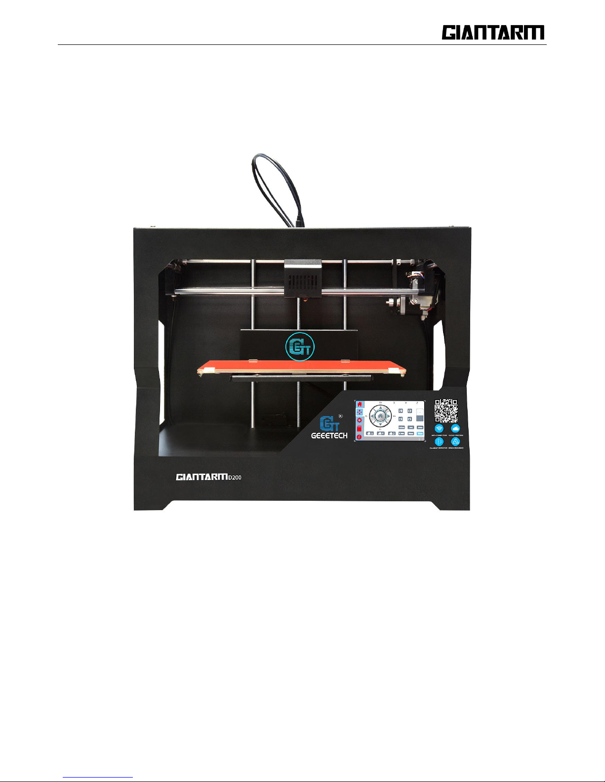
1.3 About GiantArm D200
GiantArm D200 is a user-oriented 3D printer newly launched by GiantArm, a high-end brand affiliated with
Shenzhen Getech Technology CO, LTD. GiantArm D200 is developed on the basis of FDM 3D printing
technology and prototype principle, delivering exquisite and stable 3D objects.
Wi-Fi enabled, GiantArm D200 makes it a reality to direct remote control over the whole printing process
by means of EasyPrint App, allowing you to enjoy the convenience and fashion of cloud 3D printing.
Moreover, GiantArm D200 is fully-featured: break-resuming capability, filament detector system, full-color
touch screen, modular extruder, serial nozzles, extended build volume, high resolution and fast printing
speed and etc. It is designed to get you out of frustrating printing dilemmas and provide you with
satisfactory printing experience.
Page 7
7
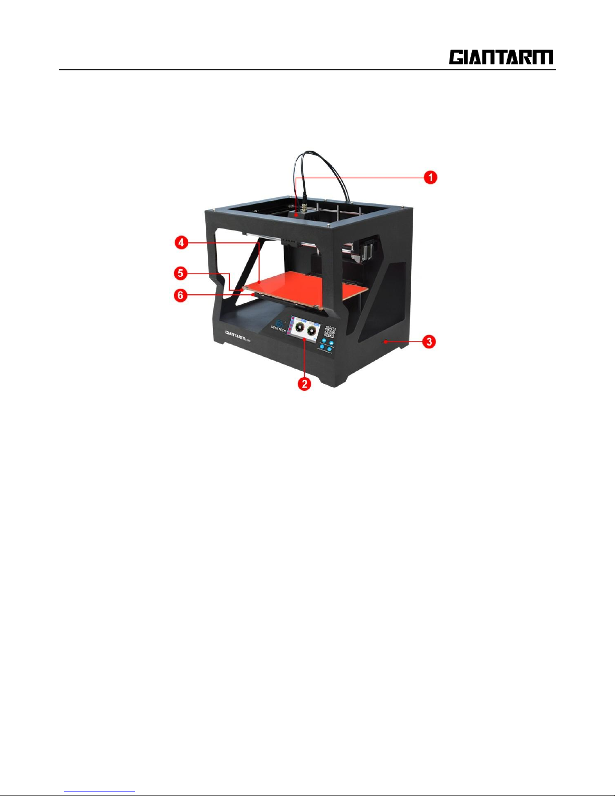
1. Extruder 2. Control panel
3. SD card slot 4. Heat-resistant glass
5. Heatbed 6.Build platform
Page 8
8
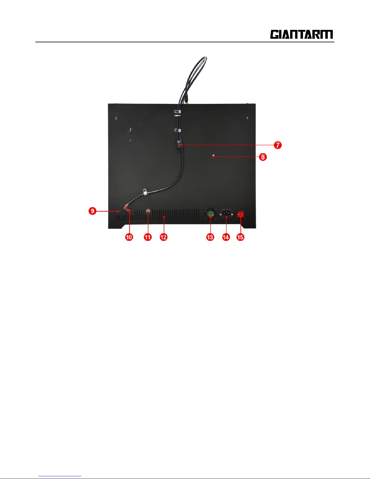
7. Filament detector 8. Spool holder 9.Wi-Fi antenna
10. Extruder bar 11. USB port 12. Air vents
13. Radiator fan 14. Power port 15. Power switch
Page 9
9
2. Unpacking GiantArm D200
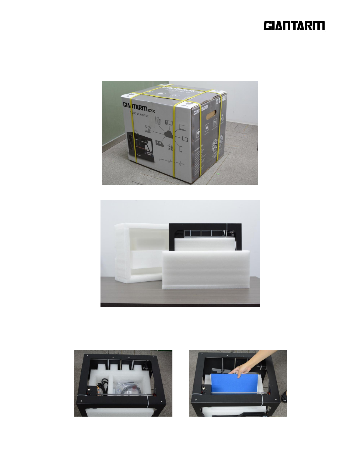
2.1 Un-box
Step 1.Open the package box
Step 2.Take out GIANTARM D200 from the box; put it on the flat surface.
Step3. Take out the accessories from the foam box in order.
Note: The glass is in the second layer of the foam box, please handle with care!
Page 10
10
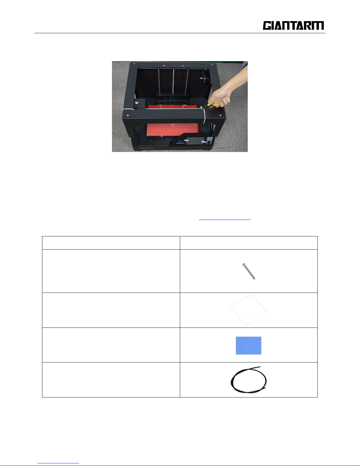
Step4. Remove the foams and cut off the zip ties.
2.2 Accessory Checklist
The accessory tray includes everything you need to use your GiantArm D200, including GIANTARM PLA
starter filament and all kinds of software sources etc which enable you quickly to start. If you want to order
more filament or purchase spare extruder hotend, please visit www.geeetech.com
Accessories
Picture
Filament spool
Heat-resistant glass
Masking tape
Bowden tube
Page 11
11
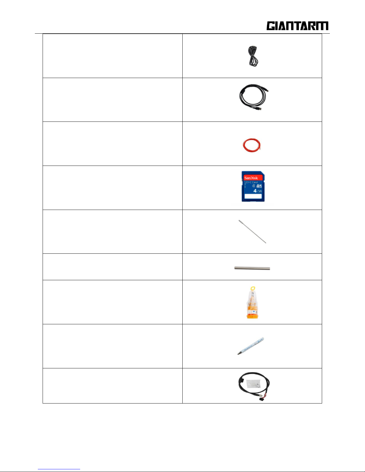
Power cable
USB cable
Starter Filament
SD card
Ejector Pin
Hotend opener
Screw driver
Ball-point pen
Extruder cable and cable clamp set
2.3 Printer set up
Page 12
12
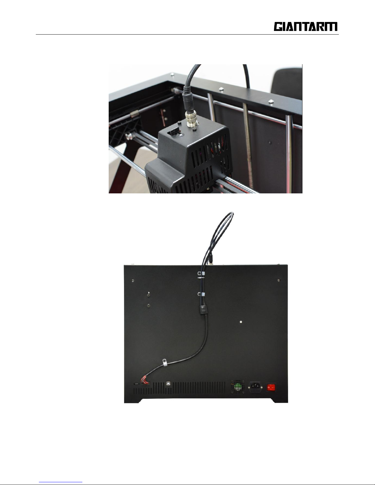
Step 1.Respectively connect with the two ends of bus wire well, and fix make it on the back of the printer
with cable clamp (you can fix the feeding pipe with it together)
Page 13
13
Step2. Fix the filament holder on the back of the printer and then hang the filament on it.
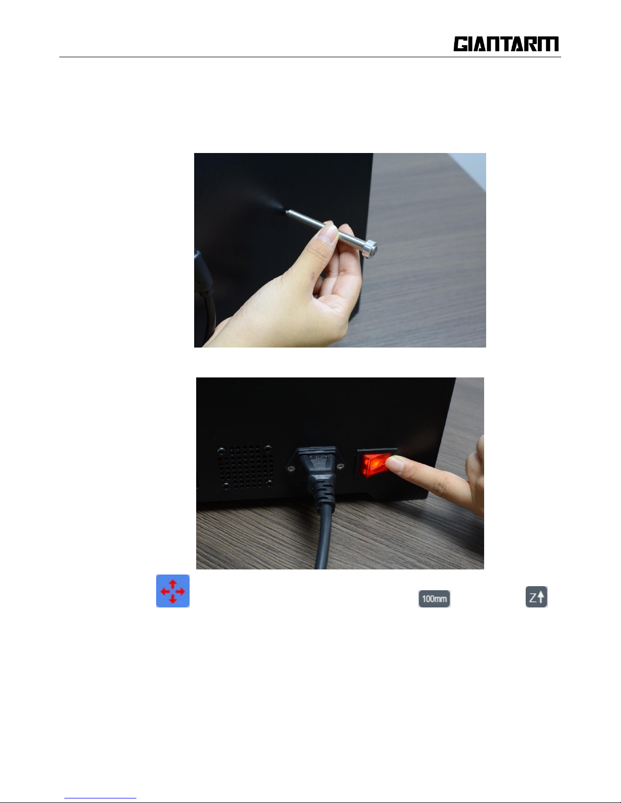
Step 3.Plug the power cable and power the printer on.
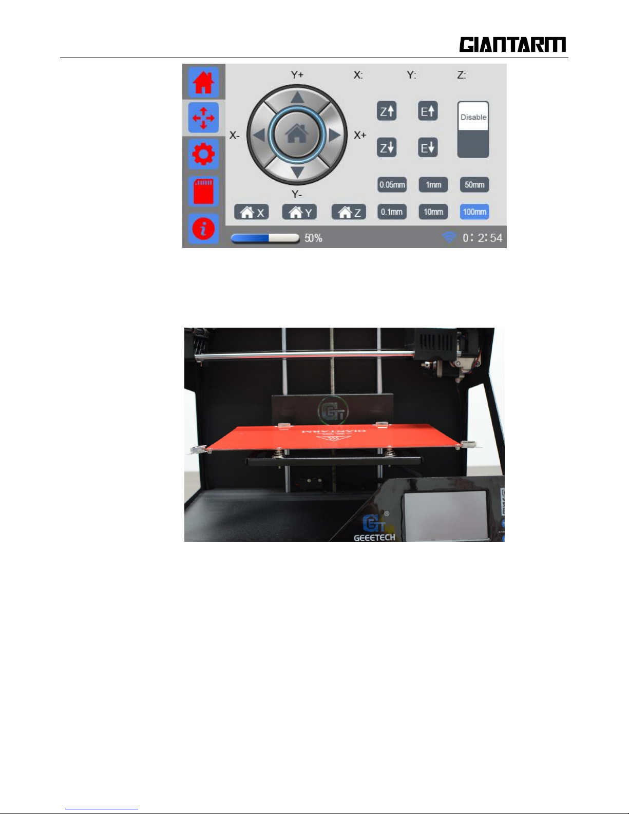
Step4. Click the icon on the screen to enter the move interface, choose , and then click
to raise the build platform to the middle.
Page 14
14
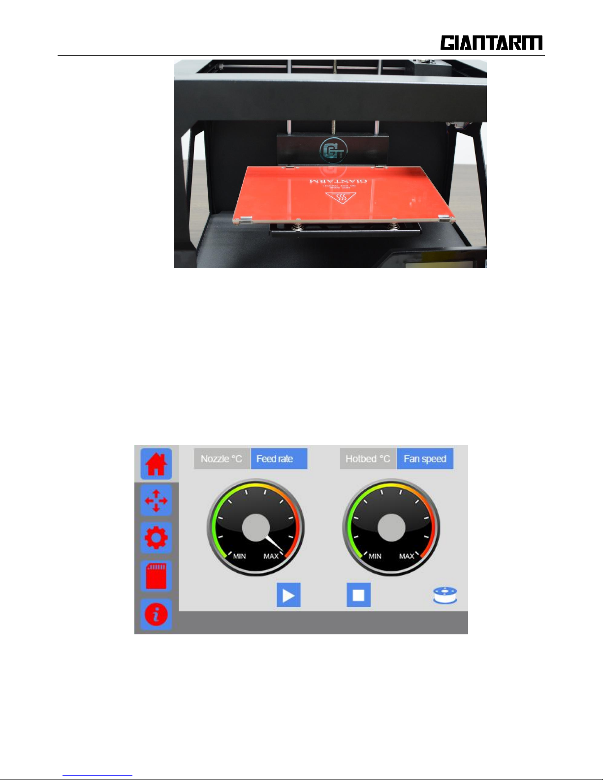
Step 5.Open the two clips on the left and the right of the heatbed, put the glass on the build platform and fix
them closely with the clips.
Page 15
15
3. GiantArm D200 Control Panel
GiantArm D200 can be controlled via the 4.3" full-color touch screen in the bottom right corner of the
printer. Stand-alone printing with SD card and remote control over the printing via EasyPrint App are
available.
3.1 Home
Page 16
16
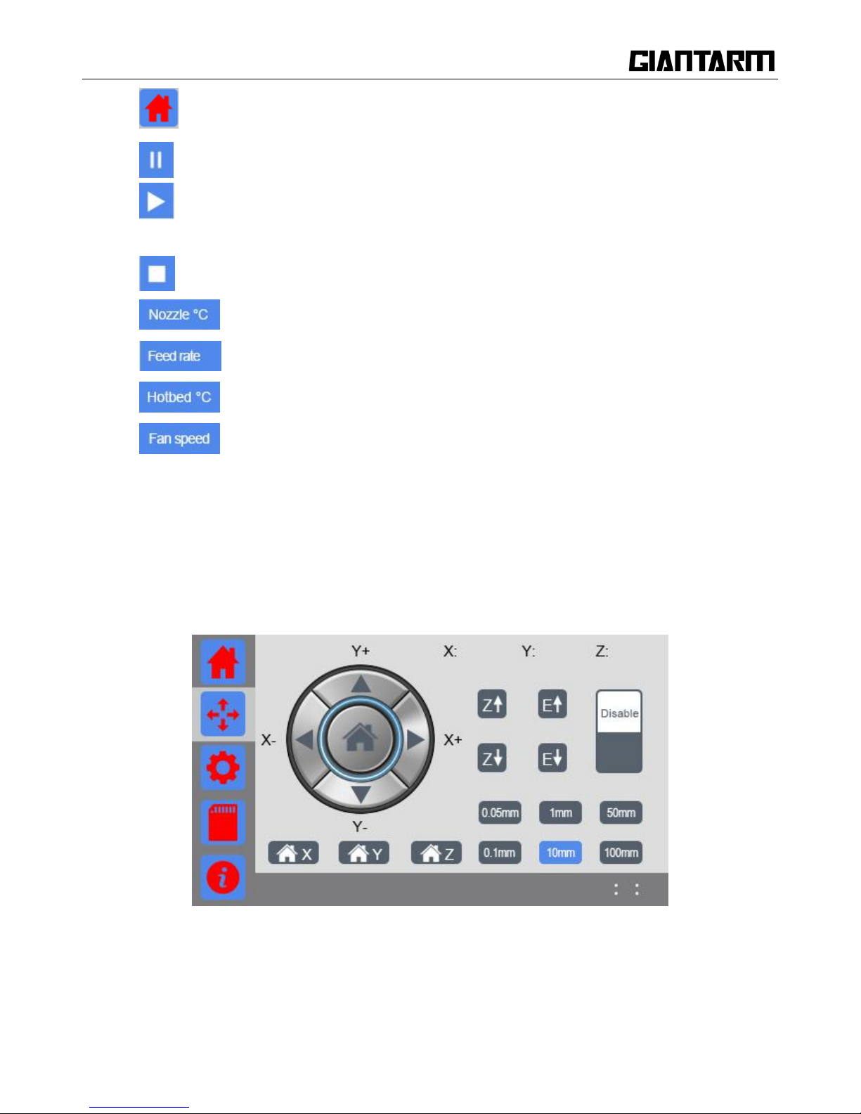
a. The icon of the main interface: Click to return to the home interface.
b. Printing: click to pause;
c. Pause: click to start printing;
d. Stop: Click to kill the present printing job;
e. Extruder temp: click to read the real-time extruder temperature on the left disk;
f. Printing speed: click to read the real-time feed rate on the left disk;
g. Hotbed temp: click to read the real-time hotbed temperature on the right disk;
h. Fan speed: click to read the real-time fan speed on the right disk.
Note: When printing via USB Serial port, the button [Printing/Pause], [stop] will hide.
3.2 Move
Page 17
17
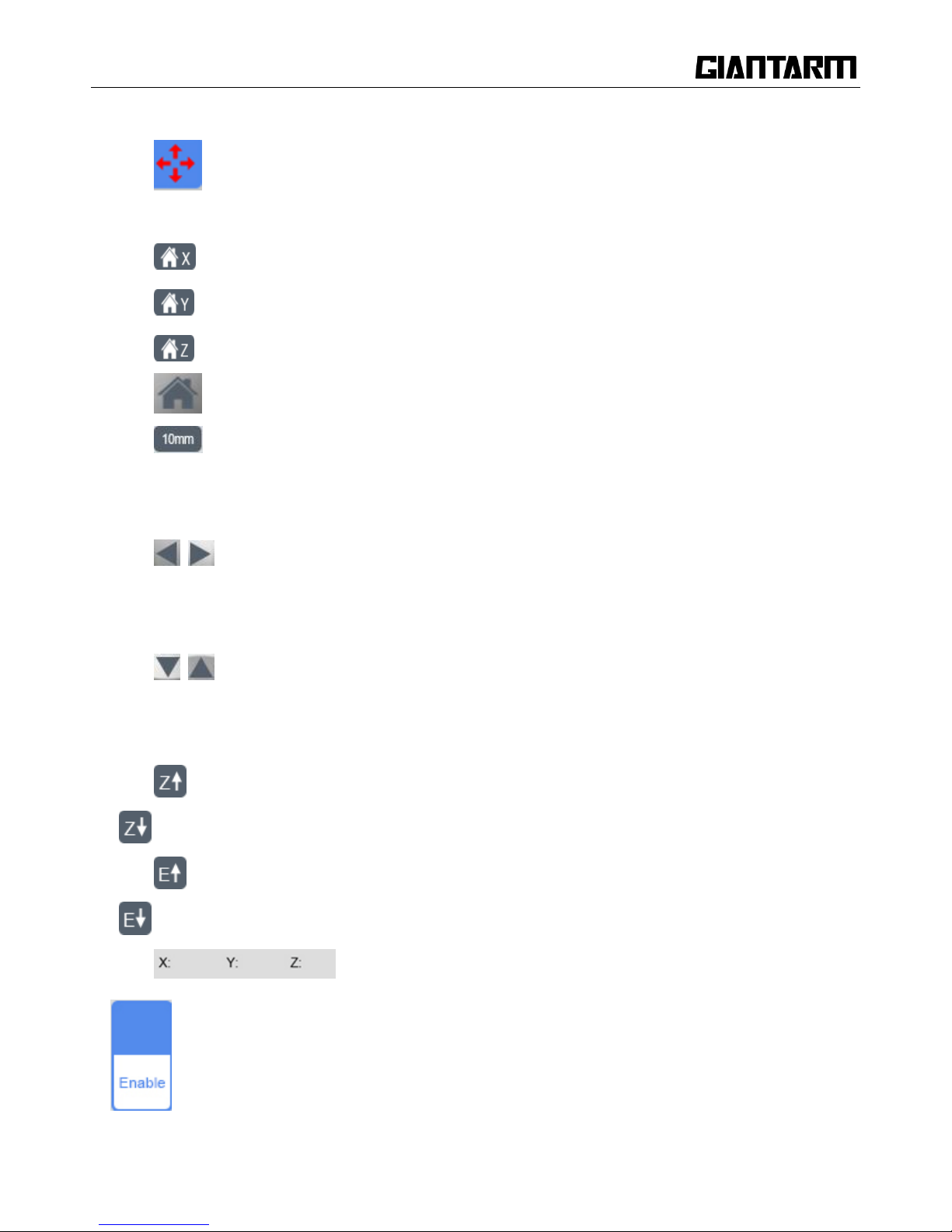
a. Move: Choose to enter the Move interface. If there is not any operation within 15s in this
interface, it will automatically return to the main interface.
b. Home X axis: Click to home the motor of X axis.
c. Home Y axis: Click to home the motor of Y axis.
d. Home Z axis: Click to home the motor of Z axis.
e. Auto home:Click to home the motors of X/Y/ Z axis simultaneously.
f. Moving distance: the moving distance of the motor or the length of filament loaded/unloaded
per click.
g. move X axis:
X-: X axis moves away from the end stop of X axis;
X+: X axis moves towards the end stop of X axis.
h. move Y axis:
Y-: Y axis moves away from the end stop of Y axis;
Y+: Y axis moves towards the end stop of Y axis.
i. Z axis moves upward away from the end stop of Z axis;
Z axis moves downward towards the end stop of Y axis.
j. Unload filament;
Load filament.
k. : Display the current coordinate of X/Y/Z axis.
l. Stepper motor Enabled status: once switched into Enabled status, the printer will home first; you
Page 18
18
can only move the motor with manual control. Click to disable the stepper motors.
Stepper motor Disabled status: you can move the motor freely with your hand. Click to enable
the stepper motors.
Note: The stepper motors are enabled when you power on the printer as default. In idle mode, if there is no
operation within 100s, the stepper motors will be disabled autonomously.
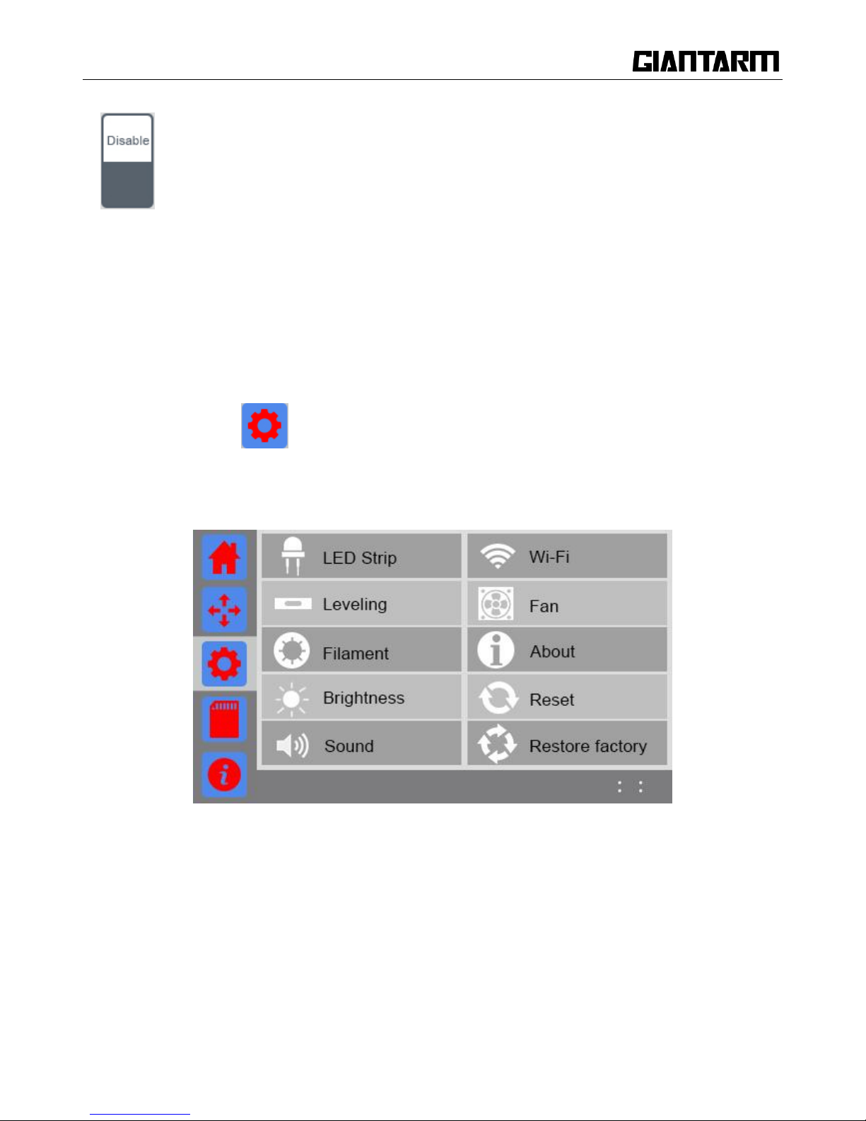
3.3 Setting
Click the setting icon and you can observe and set the relevant parameters of the following
elements as shown in the picture below.
If there is no operation within 15s, it will autonomously return to the main interface.
Page 19
19
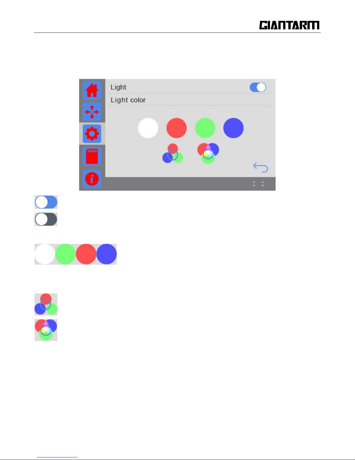
3.3.1 LED light
Select the button of LED strip to set the light color.
If there is no operation within 30s, it will automatically return to the main interface.
Turn on LED light. The default color is white when you power on the printer.;
Turn off LED light;
Single color mode: Click to choose one of the white/red/green/blue colors as you like.
Pure color flash light: the circulation of three different pure colors - Red, Green and Blue.
Gradual color flash light: the circulation of three different gradual colors of Red, Green and Blue.
Page 20
20
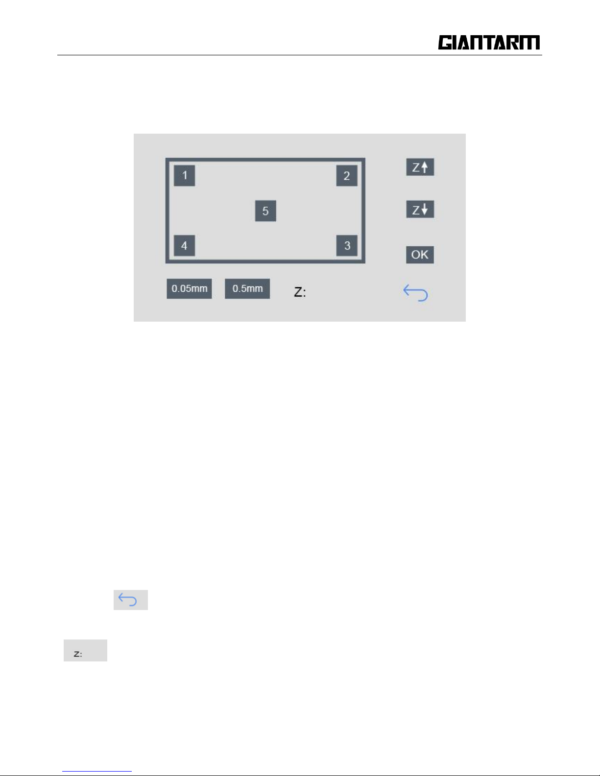
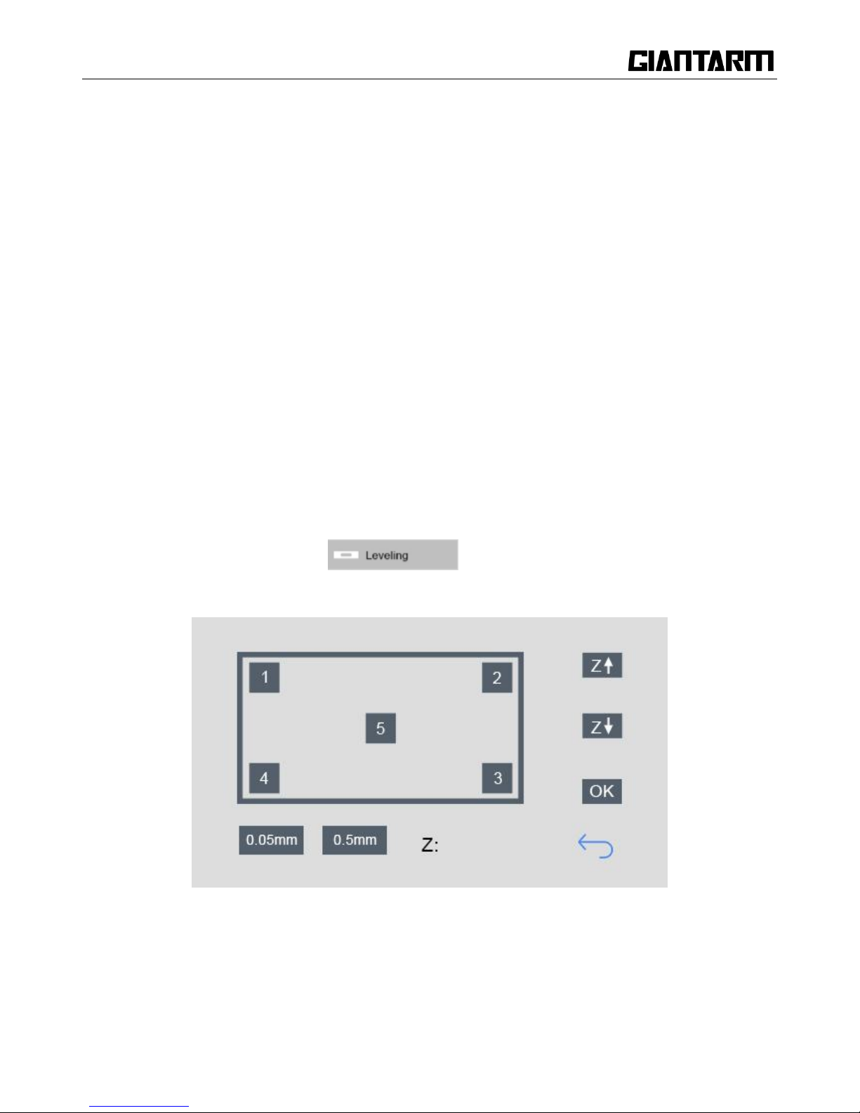
3.3.2 Leveling
Choose the [Leveling] button to enter the leveling interface. This interface is used for leveling of build
platform, as shown in the picture below.
Click to enter the interface, the printer will be homed first and Z axis will rise to 0mm to wait for leveling
Move the nozzle to the five points in turn as shown in the picture to level the platform. During this process,
you can use the z+/z- to fine-tune the position of the nozzle. Click [OK] to save the height of the platform.
a. Choose Z↑: The hotbed moves upward by 0.5mm and set the coordinate of Z axis at 0mm. The value in
the [Z:] is the updated height of the platform.
b. Choose Z↓: The platform moves downward by 0.5mm and set the coordinate of Z axis at 0mm. The
value in the [Z:] is the updated printing height.
c. Click [OK] to save the updated height of the platform.
d. Choose [1]: The platform moves downward by 10mm and the nozzle moves to the [1] point. Then the
platform moves upward to 0mm (the original coordinate of Z axis).
By that analogy, you can level the platform at the other 4 points.
e. Choose to return to the main interface of [settings]. At the same time, the motors will be
homed.
f. : Displaying the real-time height of the platform.
(Note: You can finish the leveling job of the 5 points out of sequence)
Page 21
21
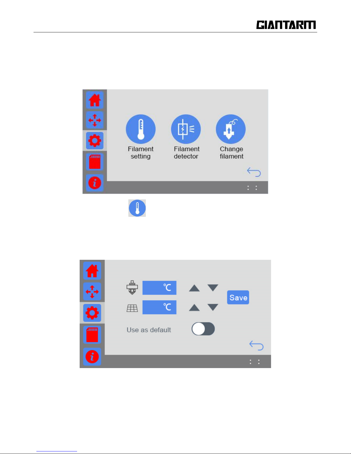
3.3.3 Filament
Choose the [Filament] button to set the relevant parameters of filament, you can set the default temp of the
extruder and hotbed, direct control over the filament detector and change filament in the half way.
If there is no operation within 30s on this interface, it will automatically return to the main interface.
1. Setting the default temp: Click to set the default temp of the extruder and hotbed as shown in the
picture below. If there is no operation within 30s on this interface, it will automatically return to the main
interface.
For the same G-code file, the user can set different target temp of the extruder and the hotbed with different
type of filament. When using this function, the printing is not influenced by the temperature value of the
G-code slicing setting but by this final setting.
Page 22
22
Turn on the default temp setting. Click the blue textbox to enter the temp value or click or long press the
button to set the suitable printing temperature for the filament .After finishing setting, you need to click
button to save your setting.
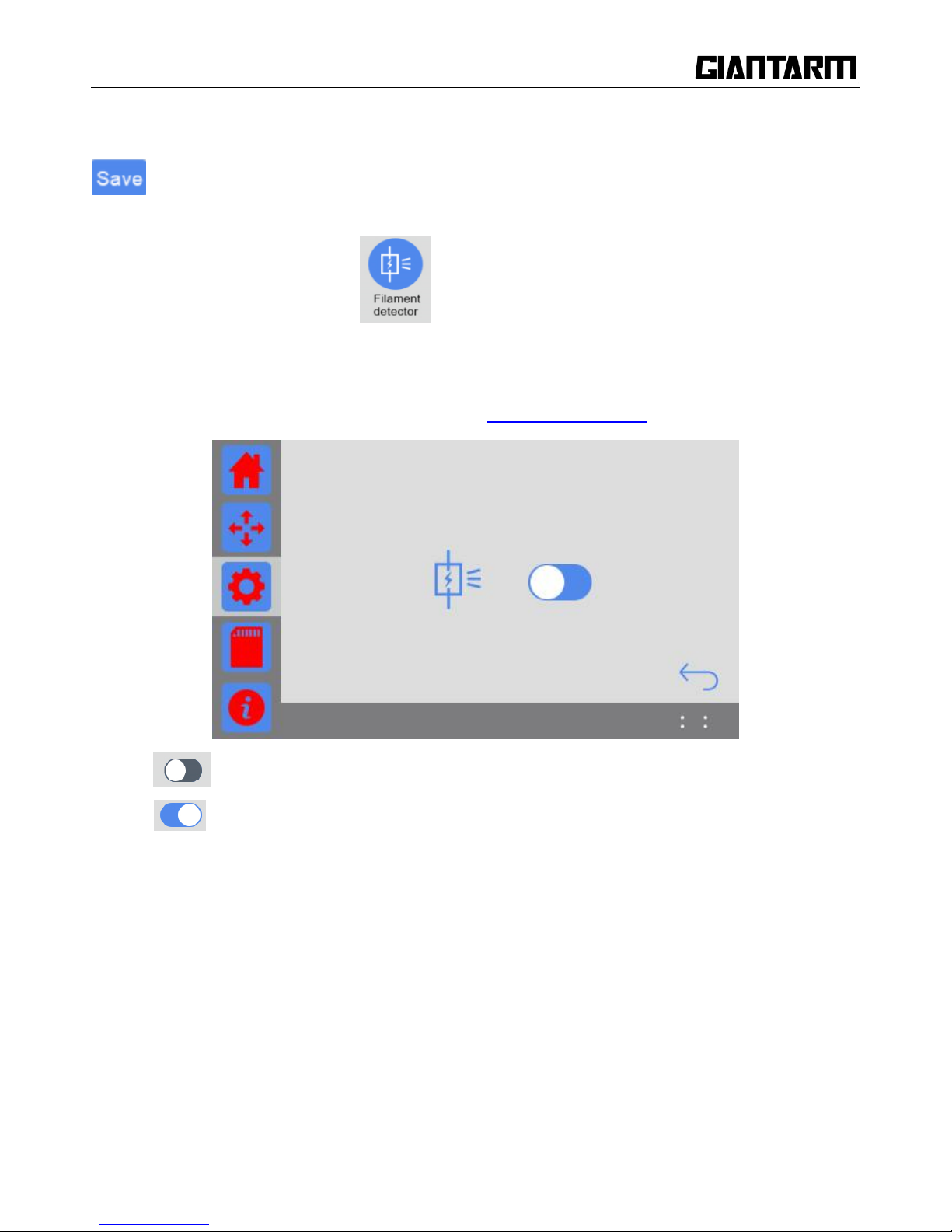
2. Filament detector: Click the icon to choose turn on/off the Filament detector.
If there is no operation within 30s on this interface, it will automatically return to the main interface, as
shown in the picture below.
For more detailed information, please make reference to 7.2 filament detector.
Turn off the filament detector;
Turn on the filament detector;
Turn on to activate the detecting system. When the filament is detected, the main panel will show the
filament icon, as shown in the picture below.
Page 23
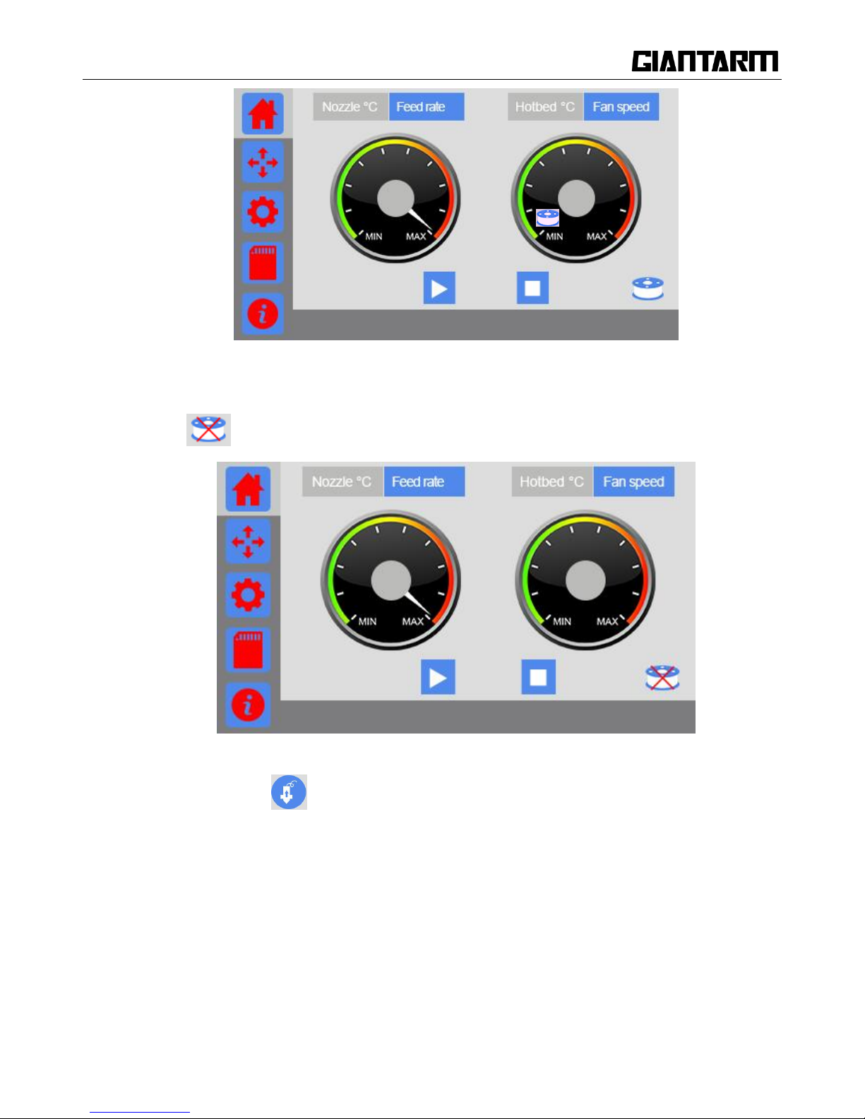
23
If the system detects an abnormal signal of filament, either filament fracture or outage, the icon will
turn into , as shown in the picture below.
3. Change filament:Click to enter the interface of changing filament as shown in the picture below.
If there is no operation within 30s on this interface, it will automatically return to the main interface.
Page 24
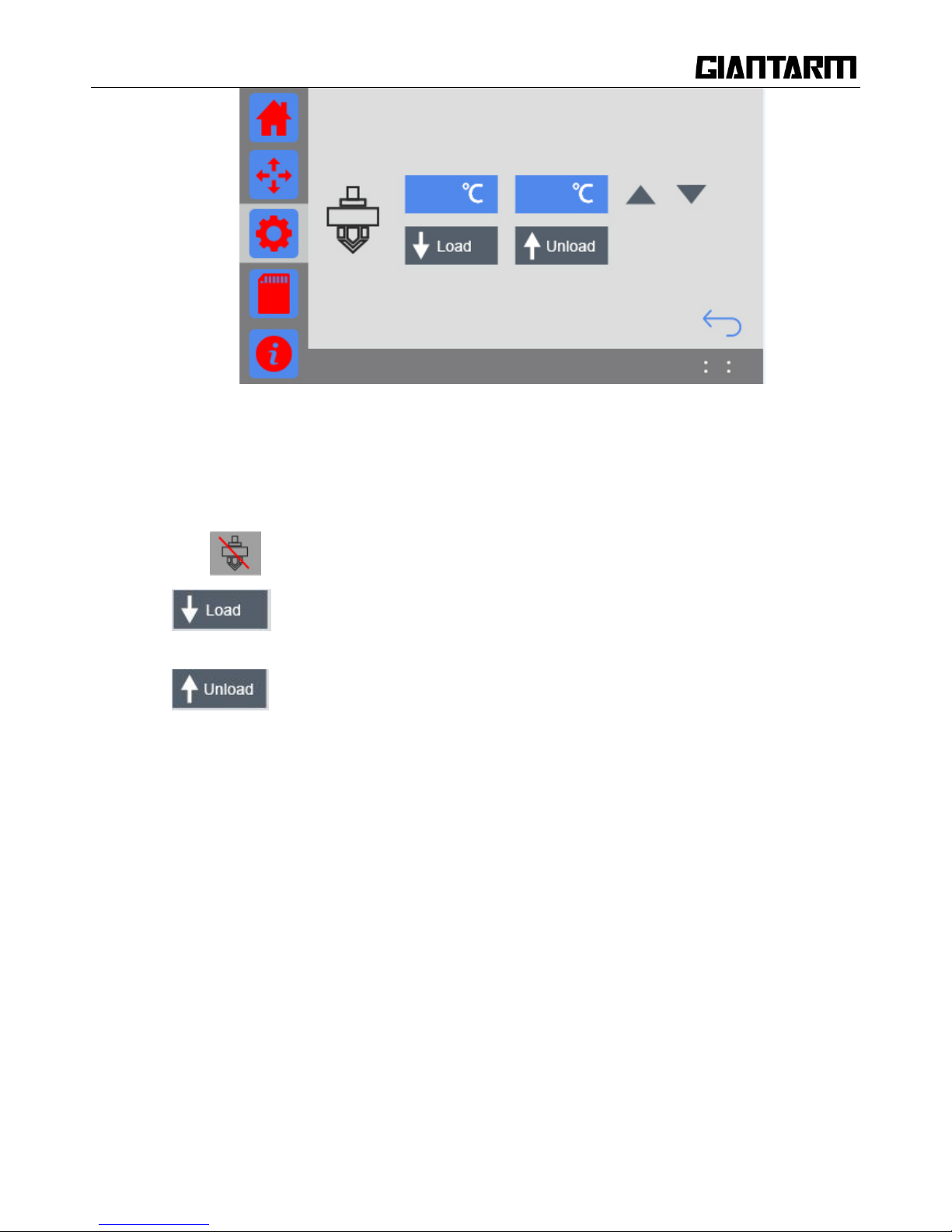
24
a. The blue textbox on the left shows the real-time temp of the extruder, and the one on the right
shows the target temp. You can modify the target temp by clicking the textbox or adjusting the
arrow button.
b. Click , the red slash will disappear and the extruder will start to heat.
c. : When the temperature of extruder reaches its target value, click Load and the
filament is extruded out by 10mm per click.
d. : When the temperature of extruder reaches its target value, click this Unload and
the filament will be retracted back by 10mm per click.
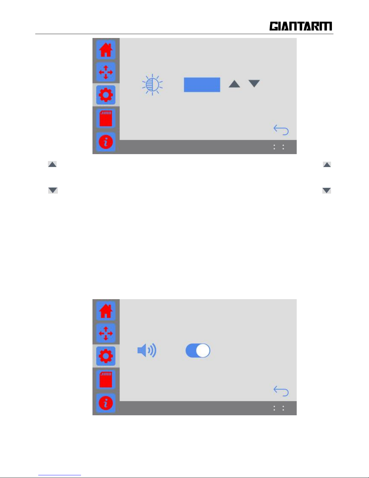
3.3.4 Brightness
Choose [Brightness] icon to enter the touch screen backlight setting interface and set the brightness
of the touch screen. The default value is 80%. If there is no operation within 30s on this interface, it
will automatically return to the main interface, as shown in the picture below.
Page 25
25
Increase: Click this button to increase the brightness by 1% per time (MAX= 100%). Long press ,
the brightness keeps increasing until it reaches 100%.
Decrease: Click this button to decrease the brightness by 1% per time (MIN= 10%). Long press ,
the brightness keeps decreasing until it reaches 10%.
3.3.5 Sound
Choose [Sound] button to enter the interface of sound setting and set the buzzer sound of the printer when it
is running. If there is no operation within 30s on this interface, it will automatically return to the main
interface,as shown in the picture below.
Buzzer sound switch: when the printer is powered on, the sound switch is open by default.
Page 26
26
Buzzer sound turns off;
Buzzer sound turns on.
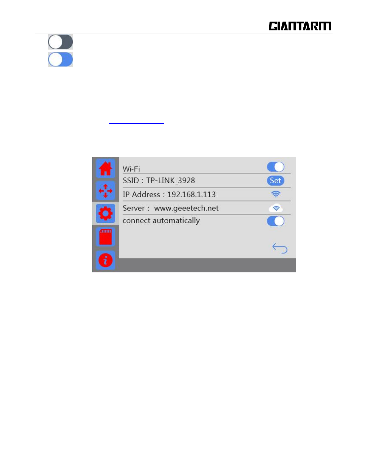
3.3.6 Wi-Fi
When you use EasyPrint App to remote control GiantArm D200, it is necessary to configure App and the
printer. (Make reference to 6.3 Print via Wi-Fi)
Choose the [Wi-Fi] icon to enter the Wi-Fi setting interface as shown in the picture below. If there is no
operation within 30s on this interface, it will automatically return to the main interface.
a. Wi-Fi switch: Click this button to turn on /off Wi-Fi.
b. Connect autonomously switch: The status of this switch can be saved when the printer is cut out.
After the printer is on and the button [connect automatically] turns on, if detecting Wi-Fi, the
printer will be automatically Wi-Fi connected.
c. The set button for SSID: Click it to configure Wi-Fi with APP.
d. SSID: Showing the name of the hotspot.
e. IP address: Showing the IP of hotspot configuration. If the Wi-Fi is disconnected; the Wi-Fi icon
turns grey; if the Wi-Fi is connected, when the Wi-Fi icon turns blue; if Wi-Fi turns off, there is
no Wi-Fi icon.
f. Server: Showing the IP of the server. If the Wi-Fi is disconnected; the Wi-Fi icon turns grey; if the
Wi-Fi is connected, when the Wi-Fi icon turns blue
Page 27
27
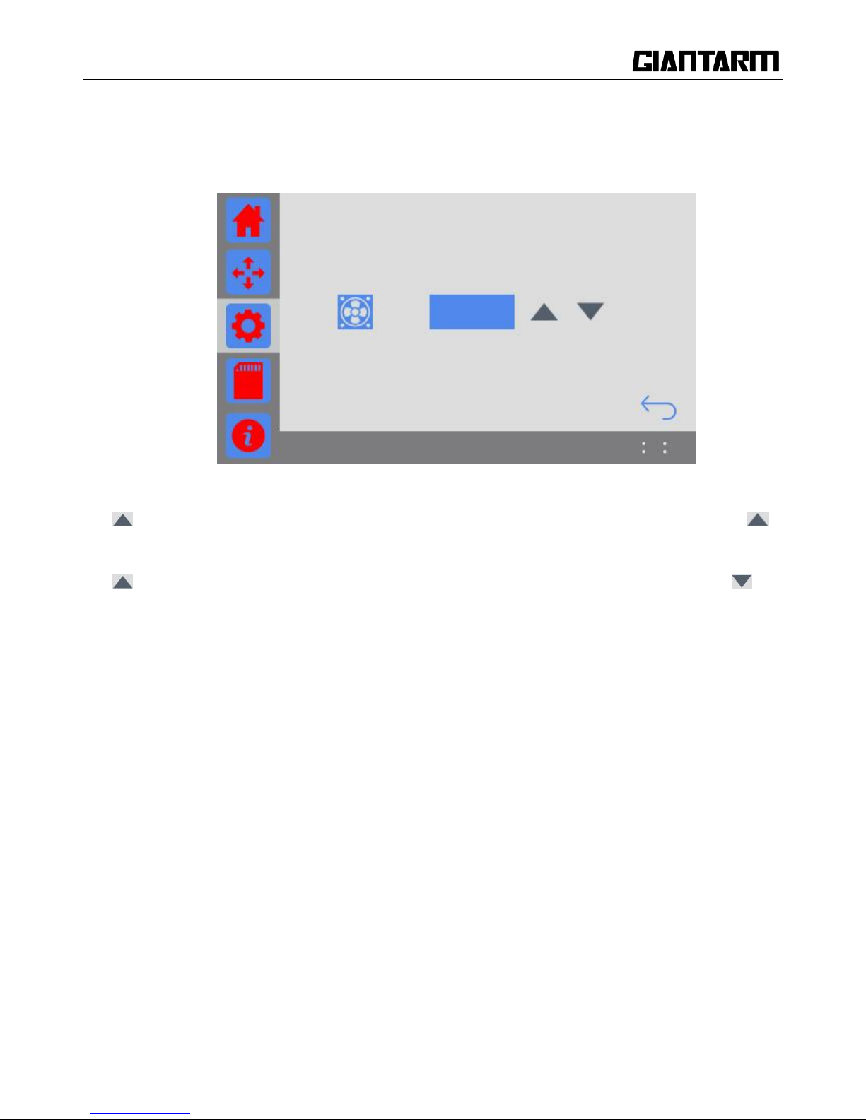
3.3.7 Fan
Choose the [Fan] icon to enter the interface and adjust the fan speed, as shown in the picture below. If there
is no operation within 30s on this interface, it will automatically return to the main interface.
Increase: Click this button to increase the fan speed by 1 per time (MAX= 100). Long press ,
the speed keeps increasing until it reaches 100.
Decrease: Click this button to decrease the fan speed by 1 per time (MIN= 0). Long press , the
speed keeps decreasing until it reaches 0.
3.3.8 About
Choose [About] icon to enter the interface of the information of device and view more information about
GiantArm D200, as shown in the picture below.
If there is no operation within 30s on this interface, it will automatically return to the main interface.
Page 28
28
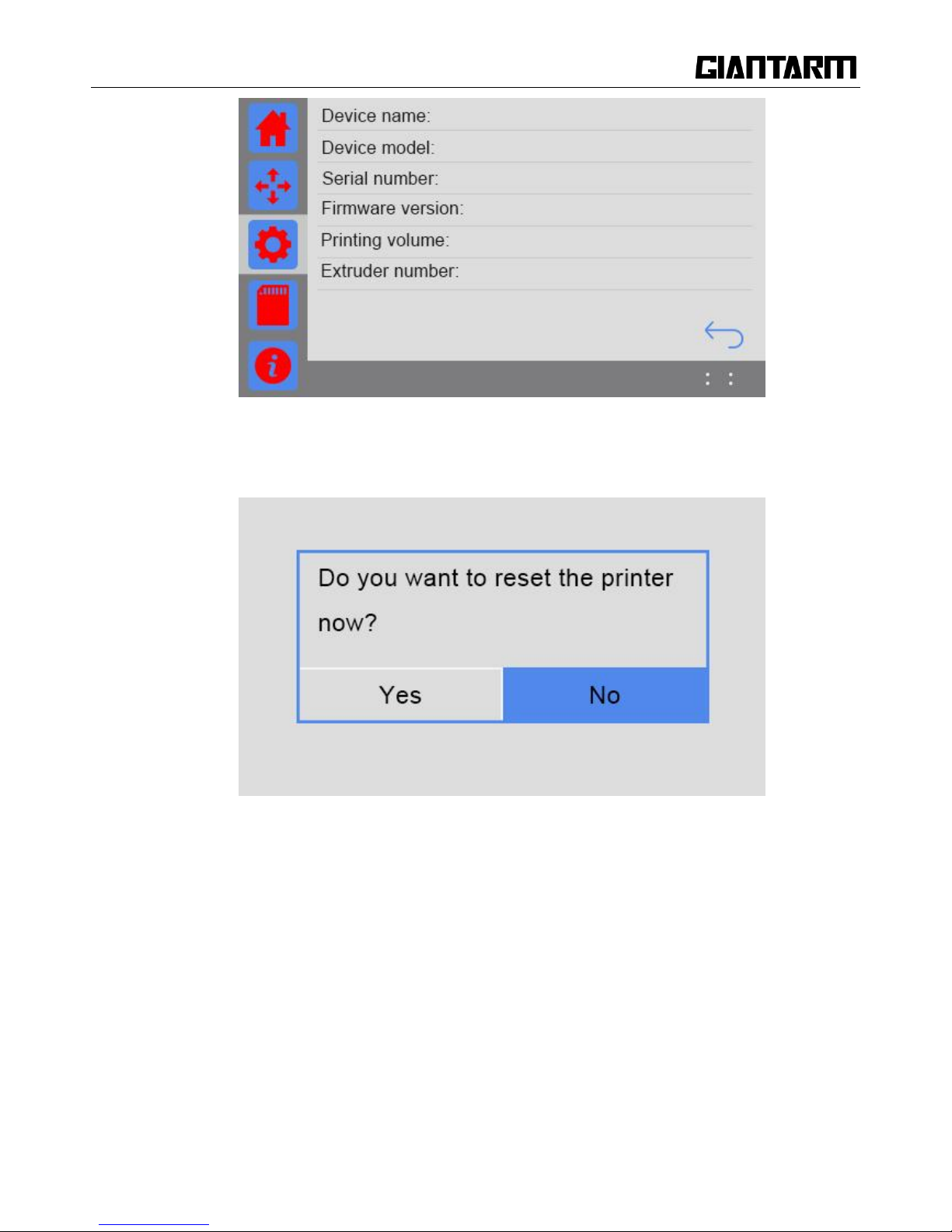
3.3.9 Reset
Choose [Reset] icon. The prompt dialog box will pop up, as shown in the picture below.
a. Choose [Yes]: The printer will save the current printing status during SD card printing, Wi-Fi
printing, or when the printing job is paused. And then the printer will reset. Otherwise it will reset
directly.
b. Choose [No] to return to the [Settings] interface.
Page 29
29
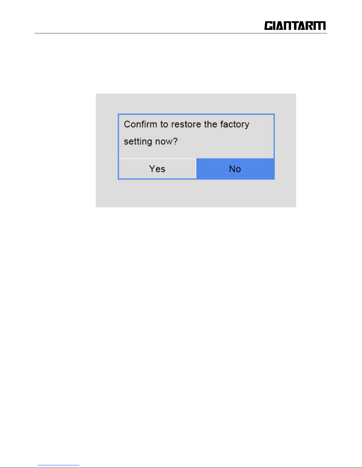
3.3.10 Restore Factory
Choose [Restore factory].
This function is disabled when the printer is running.
When the printer is not printing, a window will pop up, as shown in the picture below.
a. Choose [Yes]: Restore factory settings and restart the printer.
b. Choose [No]: Return to [Settings] interface.
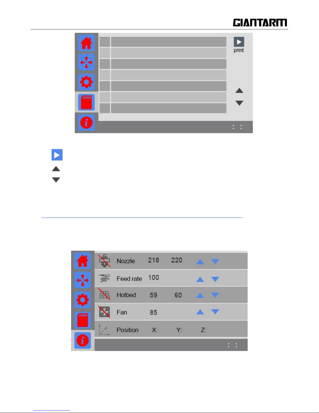
3.4 Print from SD Card
Choose SD card icon to view the 3D model files saved in the SD card. GiantArm D200 is compatible with
three file formats: .gcode, .GCO, .gco.
If there is no operation within 15s on this interface, it will automatically return to the main interface.
The following picture shows the SD card interface.
Page 30
30
a. : Select one file and click this button to start printing.
b. : Page up.
c. : Page down.
d. File name: Showing the .gcode, .GCO, .gco files in SD Card., click it to choose the file.
e. Check box: Mark the chosen file.
How to generate G-code file? Please make reference to 6.2 Print via USB Serial Port)
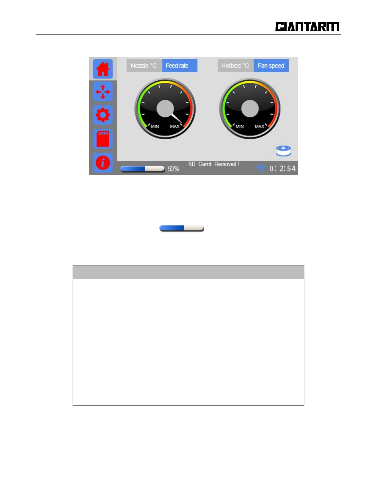
3.5 Information
Page 31

31
Click to enter the interface of Information and view the real-time printing status.
1. The temperature of the nozzle:
Click the icon to start heating the extruder. The icon turns into .
As shown in the above picture,‖218‖ and ―220‖ respectively means the current temperature of the nozzle
and the target temperature of the nozzle.
Click the number to pop up the small keyboard to set the temperature, or click /long press the arrow button
to set the temperature.
2. Feed rate:
As shown in the above picture, ―100‖ means the current temperature of the feed rate. Click the
number to pop up the small keyboard to set the feed rate, or click/ long press the arrow button to set the feed
rate.
3. The temperature of hotbed:
Click the icon to start heating the hotbed, and the icon turns into .
As shown in the above picture,‖59‖ and ―60‖ respectively means the current temperature the hotbed and the
target temperature of the hotbed.
Click the number to pop up the small keyboard to set the temperature, or click/ long press the arrow button
to set the temperature of the hotbed.
4. Fan speed
Click the icon to activate the fan, and the icon turns into
As shown in the above picture, ―100‖ means the current fan speed.
Click the number to pop up the small keyboard to set the fan speed, or click/long press the arrow button to
set the Fan speed.
5. Axis
Display the current coordinate of X/Y/Z axis.
Page 32
32
3.6 Status Bar
a. Printing status
Printing status includes printing progress bar and progress value, ranging from 0~100%, as shown in the
picture below.
50%
b. prompt message
Here you can check the status of your printer.
Triggering events
prompt message
Not detect SD card
SDCard Removed!
Detect SD card
SD Card OK!
Serial port printing(display the left
printing time)
Eg:ETE XXh XXm XXs
Display the printing files for the printing of
SD card and APP
Eg:SD1:/papa-noel.gcode
Display the printing time of finishing
printing the model
Eg:XXHours XXMinutes
Page 33

33
C. Wi-Fi icon
The status of Wi-Fi icon indicates different connection information.
①If Wi-Fi is turned off. The Wi-Fi icon will disappear.
②If Wi-Fi is turned on but not connected. The Wi-Fi will turn white;
③If Wi-Fi is turned on and connected, the Wi-Fi icon will turn blue.
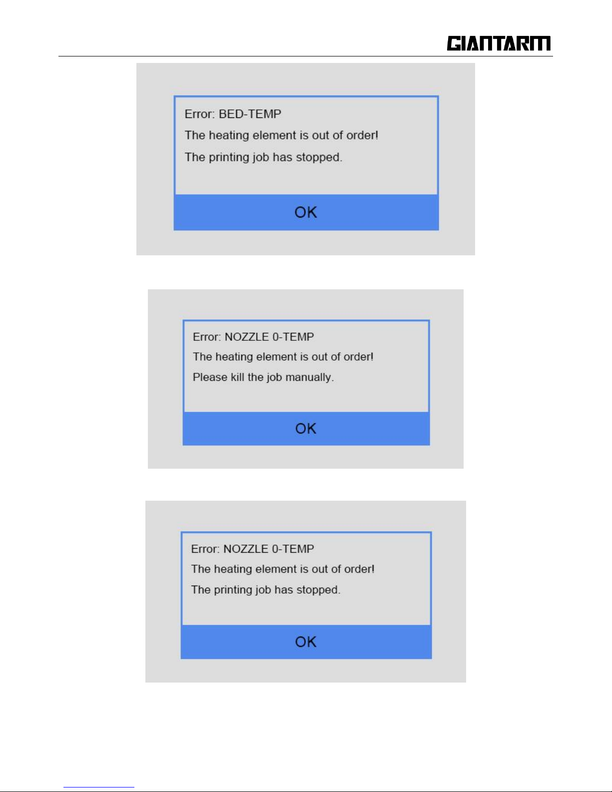
3.7 Other information
During heating, in the case of temperature changing abnormally or temperature surpassing a maximum of 30
degrees, you will see the following message:
If the printer is printing via serial port via USB connection, you need to manually stop the current printing
job;
If it is printing via SD card or Wi-Fi, the printer will stop automatically.
Then you need to check the corresponding heating elements. It may be caused by a poor connection.
(printing via serial port)
Page 34
34
(printing via SD card or Wi-Fi)
(printing via serial port)
(printing via SD card or Wi-Fi)
Page 35
35
4. Leveling
Leveling the build platform is very important to the printing quality. Before printing, we need to do hotbed
leveling to ensure the close adhesion between the print models and build platform to prevent the collision
between the nozzle and the build platform. You need to slightly adjust the height of the build platform before
your first printing. Please fine-tune the vertical distance between nozzle and hotbed. 0.1mm is the optimal
value (almost the thickness of a piece of A4 paper).
Note: Before delivery, we have leveled the build platform. Generally speaking, you can directly print.
Although we make the bundled-up packing to GIANTARM D200, the build platform may still incline a bit
during the shipping. To ensure the best printing effect, we suggest that you do the tests and calibration job
according to the following instruction.
4.1 Coarse tuning
Step 1.Choose the button [Leveling] on the setting interface to enter the ‖Leveling‖,
meanwhile the printer will home firstly,then Z axis will rise to 0mm to wait for leveling.
Step 2.Click the leveling point [5], the extruder will move to the middle of the build platform. You can
observe the distance between the nozzle and the platform.
Page 36

36
If there is an obvious gap, it means the distance between the nozzle and the build platform is too far,
the extruded filament will not be closely attached to the build platform. In this case, please click
to upraise the build platform to reduce the distance between the extruder and the build platform until
there is only a little gap between the nozzle and the build platform, and then click the button [OK] to
save the current printing height.
If you can‘t see any gap, it means the distance between the nozzle and build platform is too close.
The filament can‘t be extruded out or can even be jammed, In this case, please click to lower the
build platform to increase the distance between the nozzle and build platform until you can see a little
gap between the nozzle and the build platform, then click the button [OK] to save the current printing
height.
During this process, you can use the z+/z- to fine-tune the height of the platform.
You can choose to move 0.5mm/0.05mm per click.
Click [OK] and save the printing height of Z axis.
4.2 Fine tuning
Step1. Choose [Leveling] icon to enter the interface to start to level the hotbed.
Meanwhile the motors will be homed and Z axis will rise to 0mm.
Page 37

37
Step 2.Click the leveling point 1, the extruder will move to the first point. Put a piece of A4 paper between
the nozzle and hotbed. Slide the paper back and forth. Stop when you feel the nozzle just start to grab a little
bit.
If you cannot feel a little bit friction at all, it means the distance between the nozzle and build platform is too
far and the adhesion of filament to the hotbed will be not guaranteed. You need to anticlockwise rotate the
nut in the bottom of the hotbed which is corresponding to leveling point 1 and make the build platform raise
up to reduce the distance between the nozzle and the build platform.
Page 38

38
If you can feel a big amount of friction, it means the distance between the nozzle and build platform is too
close. The filament can‘t be extruded out or can even be jammed. You need clockwise rotate the nut in the
bottom of the hotbed which is corresponding to leveling point 1 and make the build platform drop off to
increase the distance between the nozzle and the build platform.
Step3. Move the extruder to the other 3 screw and adjust the screw until you get the same amount of friction
as you felt with the first one. Once you have adjusted each of the three screws, go back and check each one
again, since adjusting one screw can affect another. You shouldn‘t need to go around the bed more than
twice.
After leveling, the filament should be fully extruded with smooth lines and closely stick to the platform, as
shown in the picture below.
Notes:
i. When you finish leveling job, we recommend you test the build platform again to ensure the
satisfying leveling.
ii. When the printer is violently shaken during shipping and moving, the height of the build
platform may be affected. You need readjust the leveling.
iii. When there is the wrapping, curling or after you dismount the extruder, please readjust the
leveling.
iv. After restoring factory settings, we suggest you check the height of the nozzle and platform.
Page 39

39
5. Load filament
GIANTARM D200 is compatible with filaments including ABS, PLA, flexible PLA, wood-polymer, PVA,
HIPS, PETG, etc. Since different filament requests different temperature, please set temperature of the
extruder and hotbed according to the filament factory‘s proposal.
Step 1.Setting>Change filament. On this interface, you can preheat the extruder (the detailed function,
please see the part Change Filament of 3.3.3 Filament)
Here you can set the target temperature. Click the switch button of extruder to start preheat.
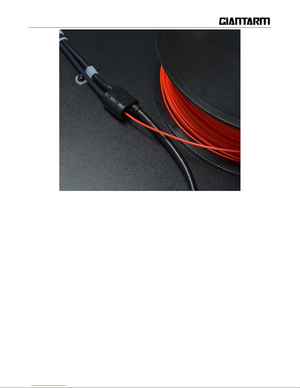
Step2. Thread the filament through the filament detector, and then pass the feeding pipe to reach the feeding
port.
Page 40
40
Step3. Sharpen the front part of filament by scissors. Press the lever bar with one hand, and insert the
filament into the tube of at the very bottom of the extruder barrel with the other hand. Please ensure the
filament reach the very bottom of the feeding port/ extruder barrel.
Page 41

41
Step 4.Once the extruder reaches the target temperature; click the button on the screen. The
hand holding the filament can obviously feel the grab from the extruder motor. Long click the button ―Load‖
until you can see the filament be extruded out smoothly from the nozzle.
If the extruder cannot normally work or the feeding is not fluent, please make reference to FAQ.
Page 42

42
6. Start to print
After finishing leveling and loading filament, you‘ve finished all the preparation work. The next step is to
print! GIANTARM D200 supports 3 ways of printing: Print form SD card, Print form USB serial port and
Print from APP (with Wi-Fi). You can download models from Internet to make the printing. Of course, you
can also design the creative objects by yourself for your printing.
6.1 Print from SD card
The easiest way is to print from SD card. GIANTARM D200 supports printing files in the following
formats: .geode, .GCO, .gco. Please ensure the file is saved in the root directory of SD card, otherwise the
printer will not detect it.
Step 1.Insert the SD card with the .gcode files into the slot on the left side of the printer. Click the SD card
icon to enter the interface of SD card, as shown in the picture below.
Step 2.Click to choose the file you want to print and it will be marked with a tick in the check box;
Step 3.Click the button ―Print‖ and start to print. The page will automatically skip to the main interface.
Page 43

43
Upon printing, the printer begins to heat up the extruder and the heatbed. On the main interface you can see
the relevant printing status on the round disk. When the temperature reaches the target value, the printer will
automatically start to print.
6.2 Print via USB Serial Port
GIANTARM provides the 3D printing control software EasyPrint 3D which is specially designed for
GIANTARMD200. EasyPrint 3D supports the model files, including g.code,.stl. The software integrates 3D
printer control and slicing. With intuitive user interface and convenient operation flow, it can cater for
different printing requests for both entry-level user and expert users alike.
For the detailed user introductions of EasyPrint 3D, please make reference to EasyPrint 3D.
http://www.geeetech.com/specialpage/software/
6.2.1 EasyPrint 3D Installation and Configuration
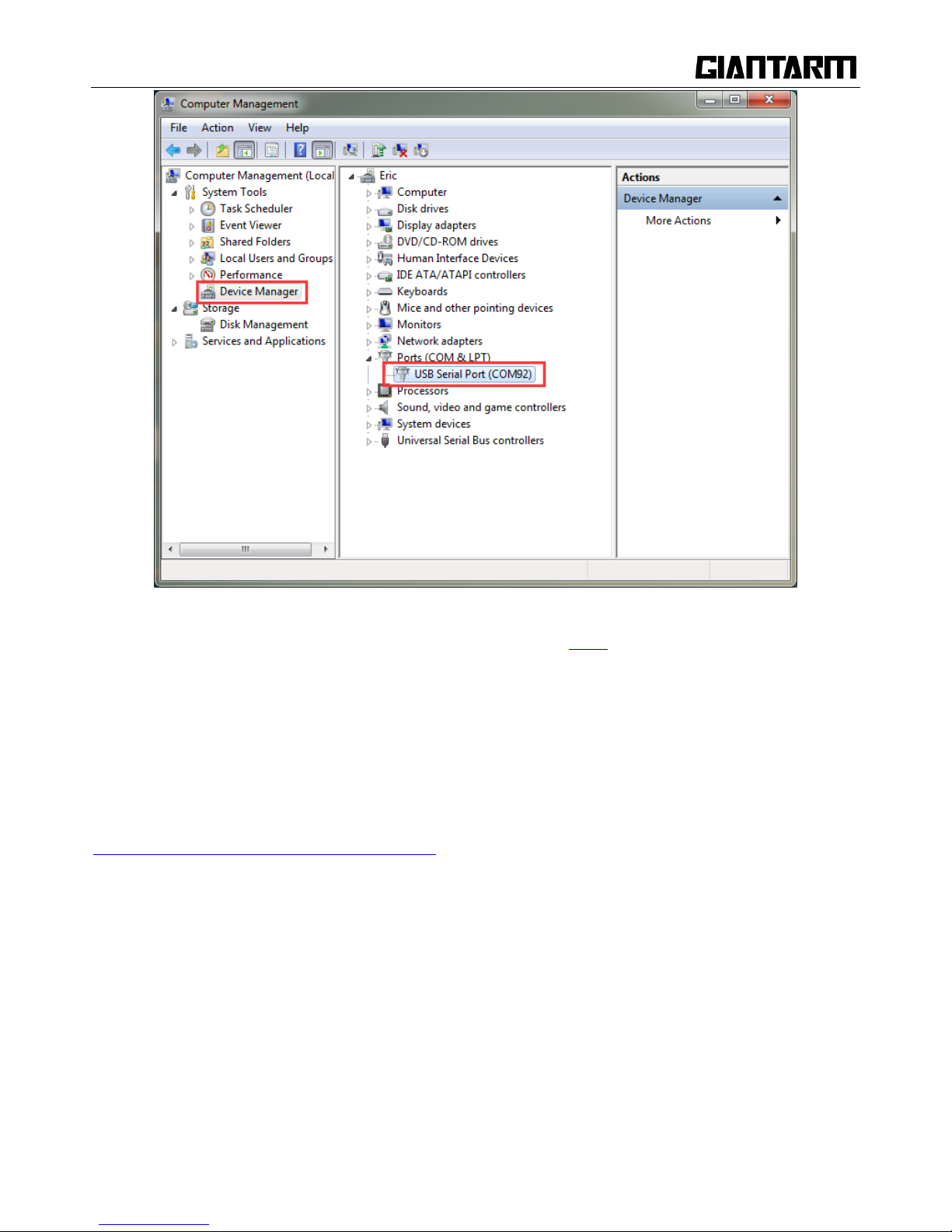
Step 1.Install the driver
Power the GIANTARM D200 up and connect it to computer with the USB cable, the driver will be installed
automatically. After installation, you can enter Device manager and find the USB Serial Port which is the
communication port for the printer and computer.
Page 44
44
If the driver cannot be automatically installed, please download the FTDI
(http://www.ftdichip.com/Drivers/VCP.htm ) or find it in the SD card and then manually install it.
Note: the COM port varies every time.
Step2. Install EasyPrint 3D
You can find EasyPrint 3D software in the SD card, or you can download it here:
http://www.geeetech.net/firmware/EasyPrint.msi. Then finish the installation following the installation
wizard.
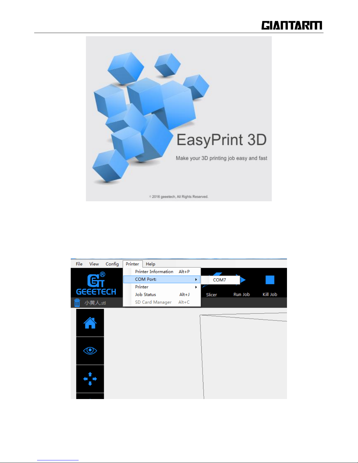
Step 3.Start EasyPrint 3D
After the installing is finished, find the icon of EasyPrint 3D. Double click it to start the software.
Page 45
45
Step4. Select the COM Port
Click the Printer menu, and then select the corresponding COM Port.
Step5. Select the Printer
Page 46

46
Click the Printer menu, and then choose the printer type as D200
Step6. Connect
Click the Connect button on the top right. You could observe the real-time status of the printer on the
bottom of the software interface.
Page 47

47
6.2.2 Load a File
Click [load] to load a.stl from your computer, or you can drag it to the 3D view window. Now you would see
your model at the center of a gray rectangle, the representation of your 3D printer‘s build plate. Then you
can use the tools on the left to edit your model.
6.2.3 Printing Setting
EasyPrint 3D provides two print setting modes: [quick] mode and [custom] mode. The [quick] mode is
designed for entry-level users, while the [custom] mode is tailored for expert users with fine printing
parameters.
Quick mode
Choose [quick] tab. Here, we have prepared 3 printing quality settings for you.
Page 48

48
Quality
High: Objects sliced with the High quality profile will have finer layers and will print more slowly.
Standard: Objects sliced with the Standard quality profile will be printed using the default settings.
Low: Objects sliced using the Low quality profile will be printed with thicker layers and will print
faster.
Infill: The density of the infilling structure.
Extruder temperature: Different filament requires different temperature for extruders; please refer to the
suggested temperature.
Layer height: the thickness of each layer. You can leave it as default.
Supports
Select this checkbox to have your object printed with support structures. Easy Print 3D will automatically
generate supports for any overhanging sections of your object. Supports will be easily removable once you
remove your finished object from the build plate.
When you have finished the setting process, click [Apply] and [OK]. The current settings will be used to
slice your model next time you print or export a print file.
Page 49
49
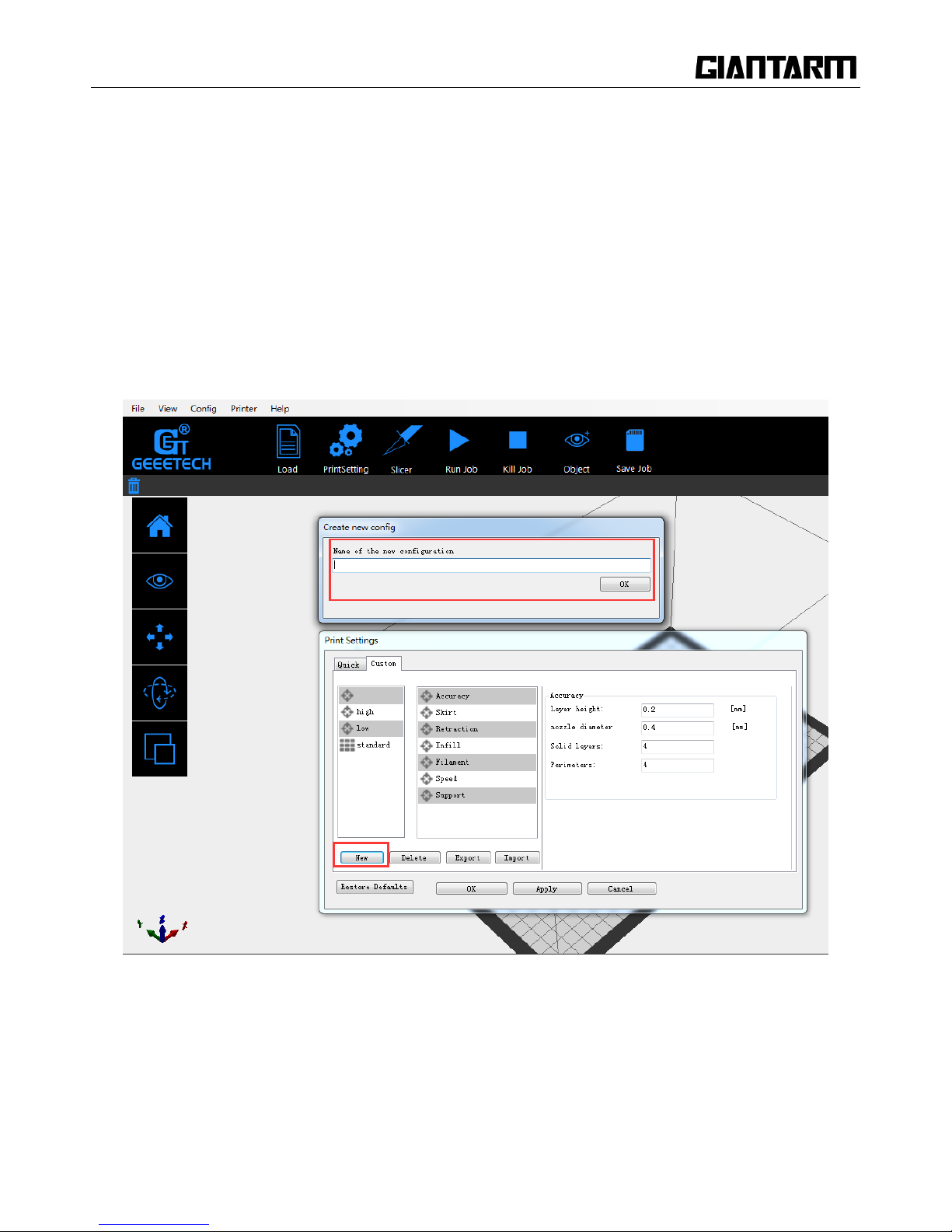
Custom Mode
For advanced users who want to exert more sophisticated control over the whole printing process, Easy Print
3D provides a series of parameters for you to engineer the printing configuration.
Step 1 Create a new configuration/setting
To customize settings, you need to create a new setting first. Click the [new] tab and enter the name of new
configuration in the textbox. Click [Ok].
Page 50
50
Step2. Custom settings
Choose the [custom] tab to enjoy the sophisticated print settings.
1) Accuracy:
a. Layer Height:
The layer height is one of the most often adjusted settings. It is the thickness of one printed layer (in mm).
With a thinner layer height you will increase the quality of the print, leading to a smoother surface and more
detail visible in the Z-direction (height) of the model. On the other hand, by using thicker layers you can
decrease the print time substantially.
b. Nozzle diameter: showing the diameter of the current nozzle.
c. Solid layers: The loops needed to finish just one layer.
d. Perimeter: The loops needed to finish printing one layer to make the printout more solid and the surface
finish smoother.
Page 51

51
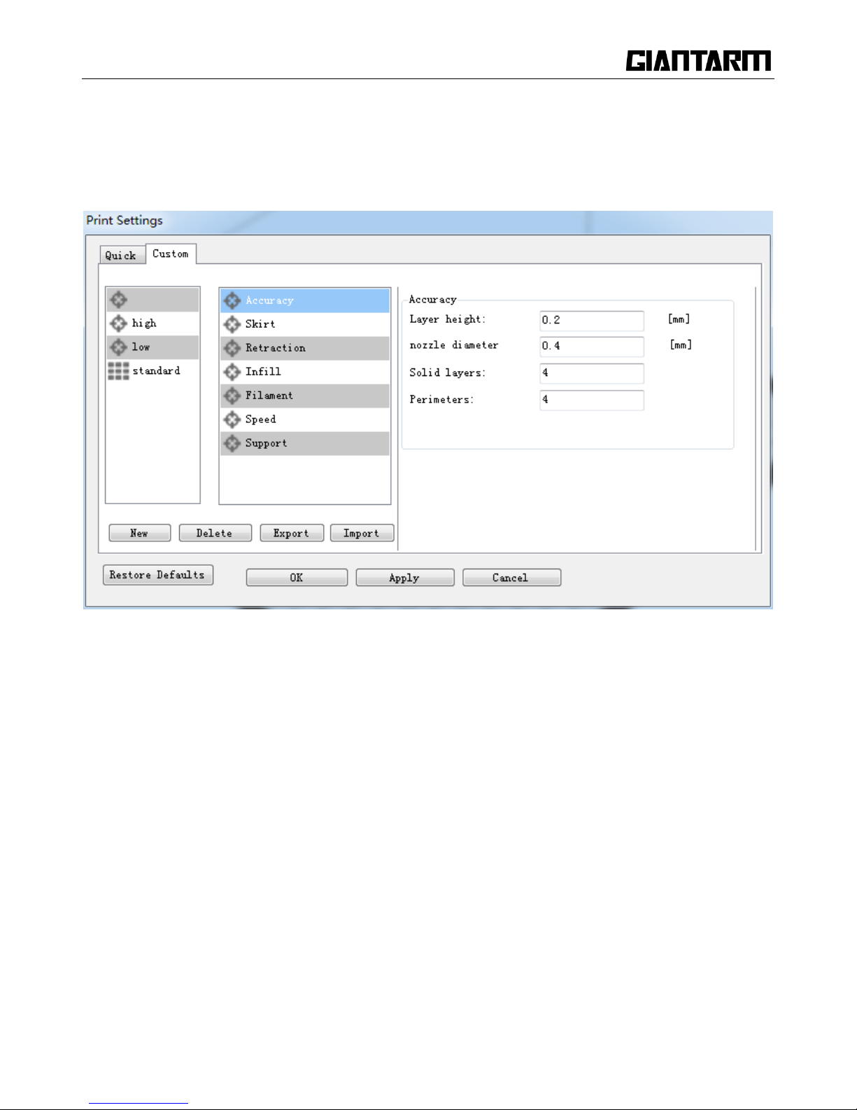
2) Skirt:
A skirt is a line printed around the object on the first layer, but not connected to the object. This helps prime
the extrusion and can also be a good check for bed leveling before the print starts and it can ensure that the
material is flowing smoothly from the extruder before it starts on the model proper.
a. Loops: The number of skirt lines printed around the model. One loop is usually sufficient.
b. Distance from object: The distance between the object and the skirt. The default of 6mm is usually
sufficient.
c. Skirt height: The number of layers to lay down a skirt for. For ensuring the material is flowing smoothly,
one layer is sufficient, however the skirt function can also be used to build walls around the object in case it
should be protected from draughts.
Page 52
52
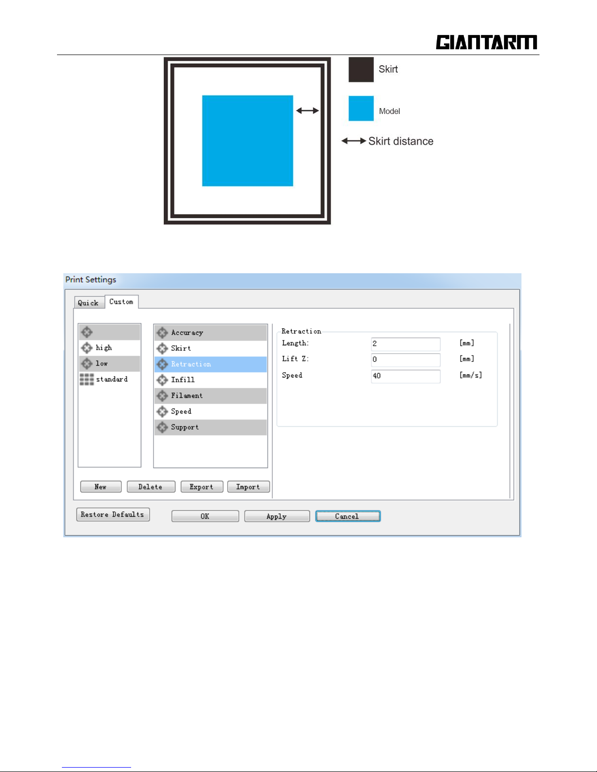
3) Retraction:
Retraction is used at the places in a print where the printer has to do a travel move between two printed parts.
Without retraction, extruded material will hang between the parts. This means that the filament is pulled
back by the feeder, so that it doesn‘t leak from the nozzle during the travel moves. By using retraction,
―stringing‖ (thin threads of plastic in between the printed parts) is prevented, resulting in a cleaner final
model. You have to be careful with flexible materials or models that require a lot of retractions, as that might
lead to grinding of the filament.
Page 53

53
a. Length: The number of millimeters to retract. Note that the measurement is taken from the raw filament
entering the extruder. A value of between 1 and 2mm is usually recommended. Bowden extruders may need
up to 4 or 5mm due to the hysteresis introduced by the tube.
b. Lift Z: Raises the entire extruder on the Z axis by that many millimeters during each travel. This can be
useful to ensure the nozzle will not catch on any already laid filament; however it is usually not necessary
and will slow the print speed. A value of 0.1mm is usually sufficient.
c. Speed: The speed at which the extruder motor will pull back the filament. The value should be set to as
quick as the extruder can handle without skipping steps, and it is worth experimenting with this value to find
the quickest retraction possible.
4) Infill:
a. Fill Density: The infill density defines the amount of plastic used inside the print. A higher infill density
means that there is more plastic on the inside of your print, delivering a stronger object. An infill density
around 20% is used for models with a visual purpose; higher densities can be used for end-use parts.
Page 54

54
c. Fill angle: By default the infill pattern runs at 45° to the model to provide the best adhesion to wall
structures. Infill extrusions that run adjacent to perimeters are liable to delaminate under stress. Some
models may benefit from rotating the fill angle to ensure the optimal direction of the extrusion.
d. Fill Pattern: It is the pattern of filling shape which effects printing duration.
Easy Print 3D offers seven infill patterns, including four regular flavors, and three more exotic ones. The
numbers on the right of each figure are a rough estimate of material used and time taken for a simple 20mm
cube model. Note that this is only indicative, as model complexity and other factors will affect time and
material.
1. Line :
350.57mm/5m: 23s
2. Rectilinear
Page 55

55
344.51mm/5mins 20s
2. Rectilinear
344.51mm/5m: 20s
3. Concentric
344.51mm/5m: 20s
4. Hilbert Curve
332.82mm /5m: 28s
5. Archimedean Chords
Page 56

56
333.66mm /5m: 27 s
6. Octagram Spiral
318.63mm/5m: 15 s
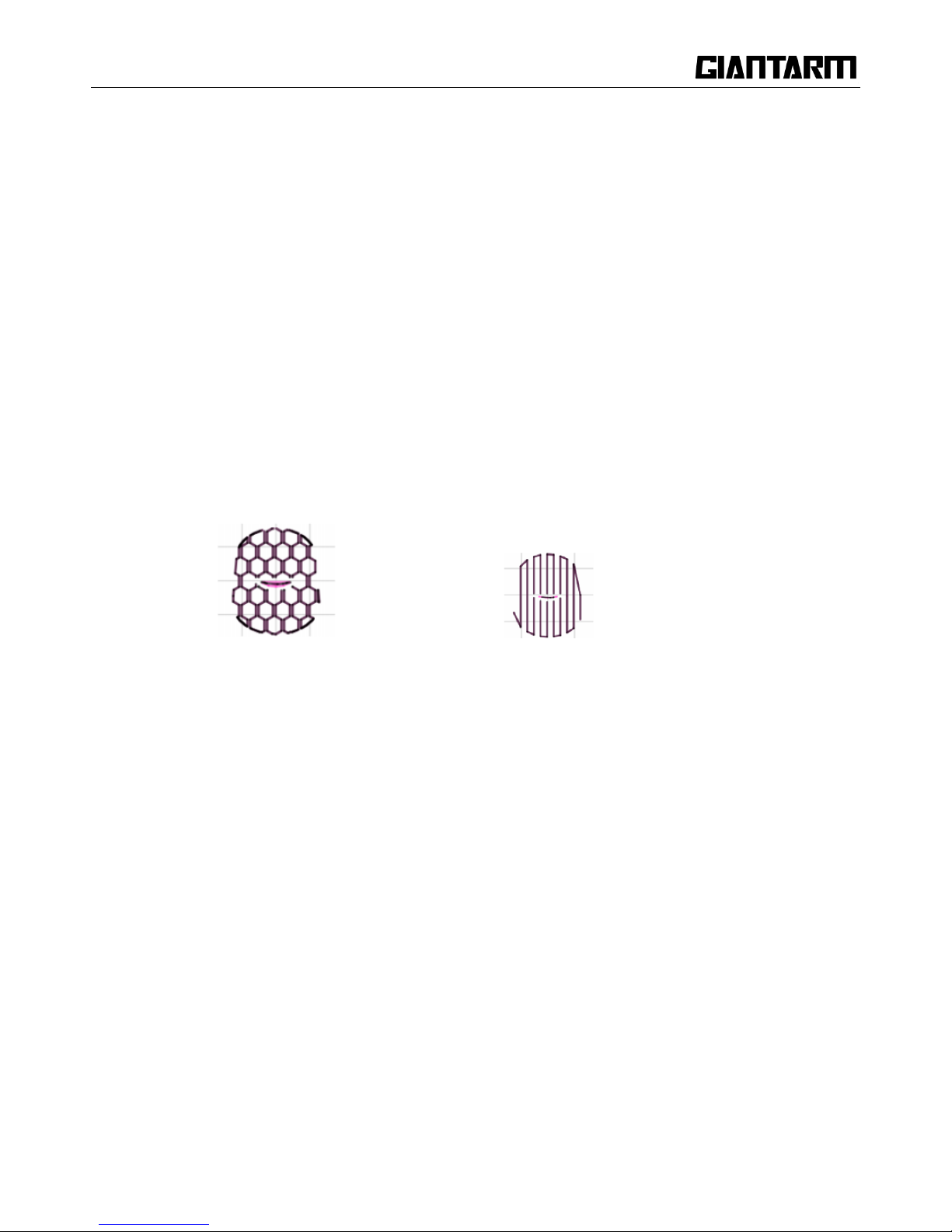
7. Honeycomb
362.73mm /5m: 39s
5) Filament:
Page 57

57
a. Diameter:
In this field you can enter the diameter of the filament, so that Easy Print 3D could calculate the extrusion
rate correctly. The most commonly used filament diameters are 1.75mm and 3mm, but it might be necessary
to change this setting when using filament from other suppliers.
b. Extrusion temperature:
This is the temperature of the nozzle during printing. The extrusion temperature can differ with different
materials. PLA, for example, needs a printing temperature of approximately 180-210 °C, while ABS needs a
higher temperature of 210 - 230 °C to properly extrude the material.
c. Heatbed temperature
For printers with a heated bed, the temperature of the heated bed can also be set here. We recommend 60 °C
for PLA and 90 -110°C for ABS to ensure that the filament sticks well to the build plate. About the
temperature requests of other filament to the hotbed, please make reference to the proposal from the filament
manufacturer.
Page 58

58
6) Speed:
The print speed defines at which speed (in mm/s) the print head moves while printing. Based on this setting,
Easy Print will also calculate how fast the filament must be extruded. A higher print speed will lead to a
shorter print time. But keep in mind that increasing the print speed means that you might have to increase
the temperature as well, to ensure the plastic is properly melted.
Although you can choose one overall print speed for the complete print, it‘s also possible to use different
print speeds for specific parts of the print:
a. Max/Min print speed: Different printer supports the different speed. Generally speaking, this
parameter is the default.
b. Travel feed rate: This is the speed at which the print head moves when it‘s not extruding, that is,
when the print head is moving from one point to another. A higher travel speed decreases the chance of
filament leaking from the nozzle, producing a cleaner object. On the other hand, a very high speed
means that the nozzle can hit an already printed part so fast that it might be damaged or deformed by
the hot nozzle. This can be prevented by using lift z when retracting though.
Page 59

59
c. First layer speed: With this setting you can specifically change the speed for the first layer of the
print. By default a low speed is used for the bottom layer, so that the material sticks well to the build plate
on the first layer. As mentioned in the above section, the first layer is important to lie down correctly, and
a slower pace helps enormously. Setting a value of 50%, or even less can really help.
d. Perimeter feed rate: The speed at which the walls are printed. You can also set the speed for the outer
and inner wall separately. Printing the outer wall a bit slower usually results in a better surface finish.
e. Infill feed rate: The speed at which the infill material is printed. Since (visual) quality of the infill is
not important, you could use a higher speed for the infill. But keep in mind that this might affect the
strength of your print.
f. Solid infill speed: The speed at which the top layers are printed. A lower speed increases the
reliability of closure of the top layers, especially on large area prints.
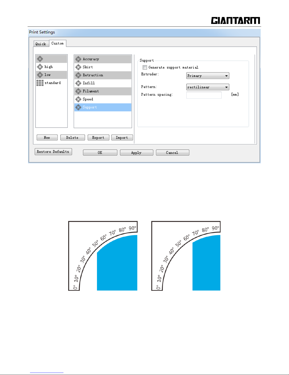
7) Support:
Page 60
60
Generally, most 3D models will print with overhanging parts by up to a certain degree. The angle is
determined by several factors, most notably layer height and extrusion width, and is usually around 45°. For
models with larger overhangs, a support structure may have to be printed below. This incurs the use of more
material, longer print time, and post-printing clean-up.
Support (the blue part)
Page 61
61
a. Generate support material
Some models have overhanging parts, which means that parts of the model float mid-air when you would
print the model. In this case you must use a support structure under the model to prevent the plastic from
falling down. This can be achieved by generating support material. Select this checkbox to have your object
printed with support structures.
b. Extruder
If you are printing with dual extruder, you can select one of them to print the support material.
c. Pattern
There are two different patterns available for printing support structures, resulting in sturdiness or the
easiness to remove the support. You can choose from the following patterns.
(1) Honeycomb (2) Rectilinear
d. Pattern Spacing
Pattern Spacing determines the distance between support lines, and is akin to infill density apart from being
defined only in mm. The adjustment of this attribute by taking into account the width of the support
extrusion and the amount of support material will adhere to the object.
Care should be taken to choose a support pattern which matches the model, where the support material
attaches perpendicularly to the wall of the object, rather than in parallel, so it will be easy to remove. If the
support structure does run along the length of a wall, the Pattern Angle option allows the direction of the
support lines to be rotated.
Now all the parameters are set. Click [Apply] and [OK] to save it.
Page 62

62
6.2.4 Slicing
After loading the model file and adjusting printing parameters, you can click the [slicer] icon to slice. It
will take a while. The slicing time depends on the size of the model.
Upon slicing, you get the sliced .gcod file.
When you are ready to print your model, click [Run job] to embark on your printing journey
Page 63

63
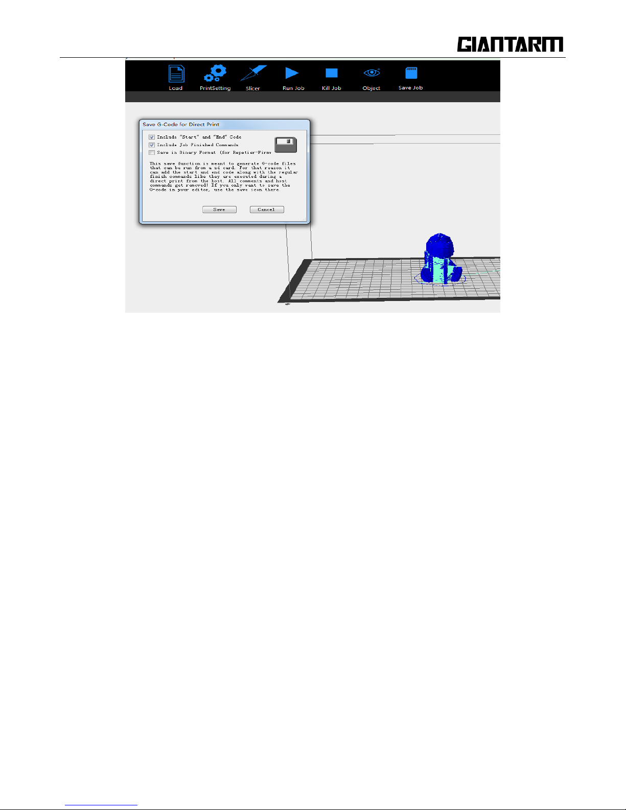
6.2.5 Save slicing
If you want to use SD card to print, we can save g.code file into SD card for printing.
Click [Save job] for SD printing and select the [save] button in the dialog box. Then g.code
file can be directly saved in SD card.
Page 64
64
Note: The file should be saved in the root directory of the SD card.
6.3 Print via Wi-Fi
GIANTARM D200 Cloud 3D printing solution conveniently provides users EasyPrint 3D App to enjoy free
and giant 3D models, just slightly press to start your printing journey. Even if you are not keeping company
with your printer, you can control the printer via EasyPrint 3D APP.
EasyPrint 3D App offers the simple, intuitive user interface, full-featured and easy-to-manage. Paired with
built-in Wi-Fi of the printer, you can select the 3D model from cloud library via APP, adjust the printing
setting in real time, monitor the printing process and save the relevant files.
EasyPrint 3D App only supports Android system so far. IOS system is under developing. Please stay tuned.
6.3.1. Install EasyPrint 3D APP
Download the EasyPrint 3D APP here and install the EasyPrint 3D APP.
Page 65

65
www.geeetech.com/firmware/EasyPrint3D_Android.apk
Once finishing installation, enter My Center to register and log in.
Note: As the EasyPrint 3D APP is continuously upgraded, some UI and workflow may be different, please
follow the APP.
6.3.2. Bind printer to EasyPrint 3D APP
Log in and bind the printer. In My Center—My 3D Printer, finish the binding process following the
instructions on APP.
Page 66

66
Page 67

67
Detailed configuration procedures are as following:
①.In Wi-Fi setting interface on the control panel, choose Wi-Fi button to enter Wi-Fi
interface, as shown in the picture below.
②.Turn on Wi-Fi and click the button “Set “to enter the Config mode, as shown in the picture below.
③.Choose Wi-Fi at the control panel on APP. At the page of pop-up, click the button“Wi-Fi” to enter
Wi-Fi configuration, as shown in the picture below.
Page 68

68
Page 69

69
④.Click [Next] to start to detect Wi-Fi built in the printer. If not detected, it will pop up a prompt “Printer
Wi-Fi is not detected”. Click [OK] and again click [Next] to redetect. If the Wi-Fi is detected, you could
see the following picture.
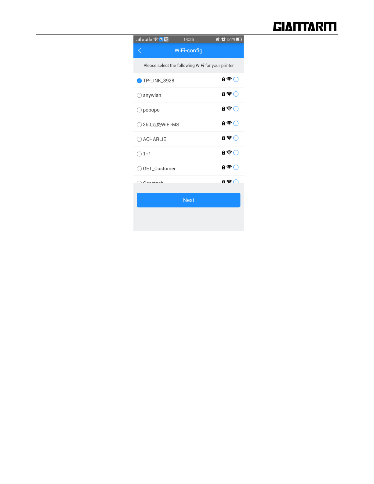
⑤ Click [Next] after Wi-Fi hotspot is detected, as shown in the picture below.
Page 70
70
⑥ Choose one of the available Wi-Fi hotspots. Click [Next], and, if the Wi-Fi needs the password, the
interface will show the Wi-Fi password input box. Just input the correct password, and then click ―[OK]”, as
shown in the picture below.
Page 71

71
⑦. When you succeed in connecting the Wi-Fi, the interface will show that the configuration is finished, as
shown in the picture below.
Page 72

72
Then the interface returns back to the control panel of the printer. You can see the prompt, as shown in the
picture below.
Click the button“Connect”on control panel, the interface will skip to Wi-Fi interface to connect with
Network. The icon and status bar of Wi-Fi become blue on Wi-Fi interface. Meanwhile, SSID, IP Address
and Server on this interface will display the relevant information, as shown in the picture below.
Page 73

73
Go back to APP, click ―[OK]”to enter the home page. The status on the homepage displays that the printer is
on-line. Till here, the configuration between APP and the printer is finished. Now you can print and control
the printing via APP.
⑧. If you choose a Wi-Fi hotspot without password, click ―Next‖ and continue your setting from step ⑦.
6.3.3 Printing from cloud library
As above, once the configuration between APP and the printer is successful, you can start to print.
Note: A SD card is still needed when print via Wi-Fi to save the files.
Step 1.Click Print —— Cloud library, choose the type of models
Page 74

74
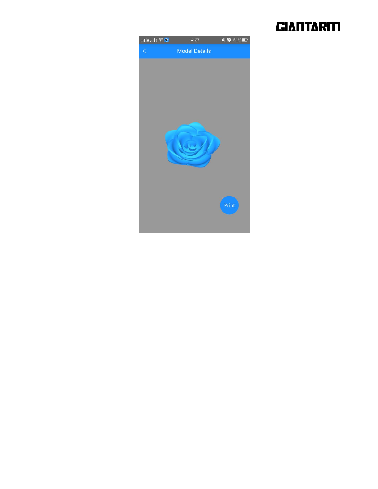
Enter the model page; choose your favorite model, let‘s take the ―Rose‖ as an example:
Enter the [Model details] page, click the button ―Print‖ here, you can preview to the model
Page 75

75
You can make some simple operations to the model on the screen with fingers, such as, zooming,
rotating or moving.
Page 76
76
Click the ―Print‖ button to start print. This will take a while to transfer the file from the cloud server to
your printer. Please keep your wireless networks unimpeded.
Page 77

77
During the uploading, you can pause the uploading or give it up.
Upon uploading, it will start printing after a while.
Page 78

78
7. Featured Functions of GIANTARM D200
7.1 Break-resuming
The break-resuming capacity, a resurrection system, is added to save real-time printing status and resume the
printing job exactly at the same place where it has been stopped. There are two kinds of conditions for pause
print: Active and Passive.
Active break-resuming capability allows you to temporarily stop the printer. In this way, you can continue
printing after replacing the filament or turn off the power to continue printing in next time. Passive
break-resuming capacity is designed to wipe out the repetitive printing job caused by unexpected power
outage. Under these two conditions, GiantArm D200 can use the stored power to record the working state
and make various parts set to the power-off condition. Once the power recovers, each axis will recover the
former state and continue the last printing job, hence effectively saving the filament, greatly increasing the
success rate of printing and providing you with a comfortable printing experience.
Page 79

79
Note: The break-resuming capacity is only available for printing from SD card or via Wi-Fi. If you print
with USB Serial port, after the power is off, the interrupted printing job can‘t be resumed.
1. Resume printing after pausing print:
Under the conditions of SD card printing and Wi-Fi printing, choose on the main interface and a
prompt will pop up, as shown in the picture below.
Choose [No] to return to the main interface. The printing continues.
Choose [Yes] and a prompt box will pop up, this prompt enables you to make the following operations:
Page 80
80
Meanwhile, the printer saves the real-time printing status and homes X/Y/Z axis.
Choose [OK] and return to the main interface.
turns into on the main interface.
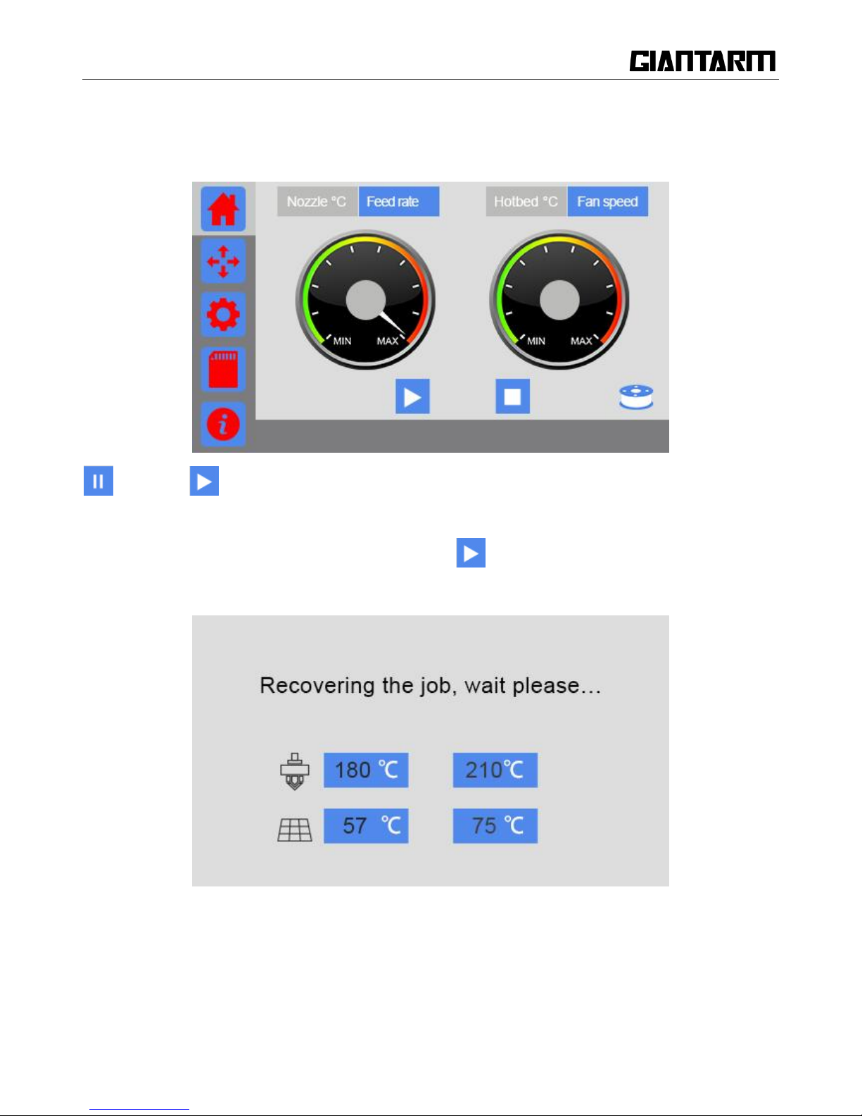
If you want to continue the last printing job, please choose and pops up the prompt ―Recovering the job,
wait please…‖ showing the heating status, as shown in the picture below.
When the heating to the target temperature, the printer will continue printing and the screen will
automatically skip to the main interface.
Tips: When your printing job pauses, you can directly turn off the printer and resume it next time.
Page 81

81
2. Resume printing after power outage:
If the printing job is interrupted by unexpected power outage when you are printing from SD card or via
Wi-Fi, the printer will save the job autonomously.
Next time when you start the printer, you will see a prompt whether to resume the interrupted print job.
An interrupted print job is detected; do you want to resume it?
Choose [Yes] to resume your printing job. Meanwhile, the following prompt will appear. Please wait for the
extruder and hotbed to reach their respective default temperature, as shown in the picture below.
Page 82

82
When the heating process finishes, the printer begins to print and the current interface returns to the main
one.
Note: If the printer does not detect the unfinished printing file, a prompt comes as follows.
You can check SD card and click [refresh] to detect the file again. If there is no response after refreshing, it
is suggested to re-insert SD card and click [refresh].
Choose [quit the job] means that you give up the unfinished object. You can select other 3D model files to
print.
3. Resume printing after Restarting:
Under the condition of SD card printing or Wi-Fi printing, no worries, if you carelessly restart the printer.
Page 83

83
The control panel will pop up a prompt of resuming printing; you can still continue the print job.
7.2 Filament detector
Filament detector is mainly developed to prevent printing failure caused by filament fracture or outage
during the printing.
Powerful filament detector system of GIANTARM can actively suspend the printing and send out an alarm
and notification (APP printing). The printer also records the real-time printing status when abnormal signal
about filament is detected.
Note:
1. The break-resuming capacity is only suitable for SD card printing or Wi-Fi printing. If you printing with
USB Serial port, when the power is off, the interrupted printing will not continue.
2. When you are loading filament, please ensure that the filament pass through the filament detector.
3. Before printing, please confirm whether the filament detector is started. (it is turned on as default.)
Page 84

84
During SD card printing or Wi-Fi printing, if the filament detector cannot detect filament, the printer will
immediately stop the current printing and the X/Y/Z axis will be homed.
The printer will also save the current status. Then the filament icon will turn into at the right bottom
corner on home page and pop ups the prompt interface of filament.
Page 85

85
①. Click [OK] to automatically return to the [Filament] interface, as shown in the picture below.
Page 86

86
②. Set the target temperature of extruder to about 200℃. Click the icon ― ‖ to heat it up. When the
temperature reaches the target value, choose [unload] to take the filament out of the extruder, and then load
the new filament.
(The details please make reference to Change filament of 3.3.3Filament)
③.After you finish changing the filament, the current interface will skip to the main interface. Click the
button ―Print‖ to continue the job.
Page 87

87
8. FAQ
As your deepening acquaintance with GIANTARM D200 3D printer, you may meet different problems
during the printing. The following are simple guidelines to help you easily solve some issues. If you need
more helps, please visit https://www.geeetech.com/wiki/index.php/Print_Quality_Troubleshooting_Guide.
8.1 About printing problem
8.1.1 Not extruding at the beginning of print
This issue is a very common one for new 3D printer owners, but thankfully, it is also very easy to resolve! If
your extruder is not extruding plastic at the beginning of your print, there are four possible causes. We will
walk through each one below and explain what settings can be used to solve the problem.
Troubleshooting
1. Extruder was not primed before beginning the print
Most extruders have a bad habit of leaking plastic when they are sitting idle at a high temperature. The hot
plastic inside the nozzle tends to ooze out of the tip, which creates a void inside the nozzle where the plastic
has drained out. This idle oozing can occur at the beginning of a print when you are first preheating your
extruder, and also at the end of the print while the extruder is slowly cooling. If your extruder has lost some
plastic due to oozing, the next time you try to extrude, it is likely that it will take a few seconds before
plastic starts to come out of the nozzle again. If you are trying to start a print after you nozzle has been
Page 88

88
oozing, you may notice the same delayed extrusion. To solve this issue, make sure that you prime your
extruder right before beginning a print so that the nozzle is full of plastic and ready to extrude. A common
way to do this in EasyPrint is by including something called a skirt. The skirt will draw a circle around your
part, and in the process, it will prime the extruder with plastic. If you need extra priming, you can increase
the number of skirt outlines on the in EasyPrint.
2. Nozzle starts too close to the bed
If the nozzle is too close to the build table surface, there will not be enough room for plastic to come out of
the extruder. The hole in the top of the nozzle is essentially blocked so that no plastic can escape. An easy
way to recognize this issue is if the print does not extrude plastic for the first layer or two, but begins to
extrude normally around the 3rd or 4th layers as the bed continues to lower along the Z-axis. To solve this
problem, you can use the very handy G-Code offsets which can be found on the G-Code tab of EasyPrint‘s
process settings. This allows you to make very fine adjustments to the Z-axis position without needing to
change the hardware. For example, if you enter a value of 0.05mm for the Z-axis G-Code offset, this will
move the nozzle 0.05mm further away from the print bed. Keep increasing this value by small increments
until there is enough room between the nozzle and the build platform for the plastic to escape.
3. The filament has stripped against the drive gear
Most 3D printers use a small gear to push the filament back and forth. The teeth on this gear bite into the
filament and allow it to accurately control the position of the filament. However, if you notice lots of plastic
shavings or it looks like there is a section missing from your filament, then it‘s possible that the drive gear
has removed too much plastic. Once this happens, the drive gear won‘t have anything left to grab onto when
it tries to move the filament back and forth. Please see the Grinding Filament section for instructions on how
to fix this issue.
4. The extruder is clogged
If none of the above suggestions are able to resolve the issue, then it is likely that your extruder is clogged.
This can happen if foreign debris is trapped inside the nozzle, when hot plastic sits inside the extruder too
long, or if the thermal cooling for the extruder is not sufficient and the filament begins to soften outside of
the desired melt zone. Fixing a clogged extruder may require disassembling the extruder, so please contact
your printer manufacturer before you proceed. We have had great success using the ―E‖ string on a guitar to
unclog extruders by feeding it into the nozzle tip; however, your manufacturer should also be able to provide
recommendations.
Page 89

89
8.1.2 Print Not Sticking to the Bed
It is very important that the first layer of your print is strongly connected to the printer‘s build platform so
that the remainder of your part can be built on this foundation. If the first layer is not sticking to the build
platform, it will create problems later on. There are many different ways to cope with these first layer
adhesion problems, so we will examine several typical causes below and explain how to address each one.
Troubleshooting
1. Build platform is not level
Many printers include an adjustable bed with several screws or knobs that control the position of the bed. If
your printer has an adjustable bed and you‘re having trouble getting your first layer to stick to the bed, the
first thing you will want to verify is that your printer‘s bed is flat and level. If the bed is not level, one side
of your bed may be too close to the nozzle, while the other side is too far away. Achieving a perfect first
layer requires a level print bed. EasyPrint already includes a useful bed leveling wizard that you guide you
through the bed leveling process. You can find this wizard by going to Tools > Bed Leveling Wizard, and
following the on-screen instructions.
2. First layer is printing too fast
As you extrude the first layer of plastic on top of the build platform, you want to make sure that plastic can
properly bond to the surface before starting the next layer. If you print the first layer too fast, the plastic may
not have time to bond to the build platform. For this reason, it is typically very useful to print the first layer
at a slower speed so that the plastic has time to bond to the bed. EasyPrint provides a setting for this exact
Page 90

90
feature. Go to the speed tab; you will see a setting labeled ―First Layer Speed‖. For example, if you set a
first layer speed of 50%, it means that your first layer will print 50% slower than the rest of your part. If you
feel that your printer is moving too fast on the first layer, try reducing this setting.
8.1.3 Stringing or Oozing
Stringing (otherwise known as oozing, whiskers, or ―hairy‖ prints) occurs when small strings of plastic are
left behind on a 3D printed model. This is typically due to plastic oozing out of the nozzle while the extruder
is moving to a new location. Thankfully, there are several settings within EasyPrint 3D that can help with
this issue. The most common setting that is used to combat excessive stringing is something that is known as
retraction.
If retraction is enabled, when the extruder is done printing one section of your model, the filament will be
pulled backwards into the nozzle to act as a countermeasure against oozing. When it is time to begin printing
again, the filament will be pushed back into the nozzle so that plastic once again begins extruding from the
tip. To ensure retraction is enabled, click ―Settings‖, choose [custom] mode and click on Retraction tab. In
the sections below, we will discuss the important retraction settings as well as several other settings that can
be used to combat stringing, such as the extruder temperature settings.
Page 91

91
Troubleshooting
1. Retraction distance
The most important retraction setting is the retraction distance. This determines how much plastic is pulled
out of the nozzle. In general, the more plastic that is retracted from the nozzle, the less likely the nozzle is to
ooze while moving. Most direct-drive extruders only require a retraction distance of 0.5-2.0mm, while some
Bowden extruders may require a retraction distance as high as 15mm due to the longer distance between the
extruder drive gear and the heated nozzle. If you encounter stringing with your prints, try increasing the
retraction distance by 1mm and test again to see if the performance improves.
2. Retraction speed
The next retraction setting that you should check is the retraction speed. This determines how fast the
filament is retracted from the nozzle. If you retract too slowly, the plastic will slowly ooze down through the
nozzle and may start leaking before the extruder is done moving to its new destination. If you retract too
quickly, the filament may separate from the hot plastic inside the nozzle, or the quick movement of the drive
gear may even grind away pieces of your filament. There is usually a sweet spot somewhere between
1200-6000 mm/min (20-100 mm/s) where retraction performs best. Thankfully, EasyPrint has already
provided many pre-configured profiles that can give you a starting point for what retraction speed works
best, but the ideal value can vary depending on the material that you are using, so you may want to
experiment to see if different speeds decrease the amount of stringing that you see.
3. Temperature is too high
Once you have checked your retraction settings, the next most common cause for excessive stringing is the
extruder temperature. If the temperature is too high, the plastic inside the nozzle will become extremely
viscous and will leak out of the nozzle much more easily. However, if the temperature is too low, the plastic
will still be somewhat solid and will have difficulty extruding from the nozzle. If you feel you have the
correct retraction settings, but you are still encountering these issues, try decreasing your extruder
temperature by 5-10 degrees. This can have a significant impact on the final print quality. You can adjust
these settings by clicking ―Edit Process Settings‖ and selecting the Temperature tab. Select your extruder
from the list on the left, and then double-click on the temperature set point you wish to edit.
For more tips on improving printing quality, please take a glance at:
https://www.geeetech.com/wiki/index.php/Print_Quality_Troubleshooting_Guide .
Page 92
92
8.2 How to upload the firmware?
EasyPrint 3D provides all the users with online service of upgrading firmware to guarantee perfect printing
performance.
The specific method is as follows:
1. Connect your GEEETECH 3D printer to the computer with the USB cable.
2. Turn the printer on.
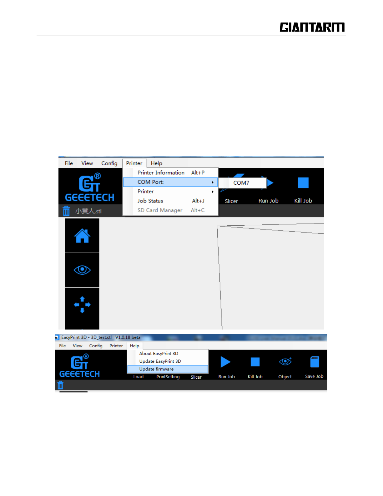
3. In Easy Print 3D, choose the COM port and the printer type.
4. Click ‘help‘> 'Update firmware'.
After clicking the [upgrade firmware] tab, a window will pop up with the information of printer type and
port, the current firmware version installed, the available version and the update summary of the latest
firmware.
Page 93

93
Click updates and confirms updating, the progress bar will turn green, and the firmware will be updated
automatically. This process may take some time.
When the upload is complete the message ‗update successes will be displayed.
Page 94

94
Click ‗ok‘ and ‗Close‘ on the windows to complete the firmware upgrade.
8.3 How to change the extruder
The extruder of GiantArm D200 is characterized by its modular design. Specifically speaking, the coldend
and hotend are combined together by a sliding joint, making it easy to change the extruder.
1) Find the switch on the left of the nozzle and slide it to the left slowly to take out the nozzle;
Here is the picture after you move the nozzle.
Page 95

95
2) Assemble the new nozzle and slide the switch to the right to lock the nozzle. This is the operation flow of
change a new nozzle.
Page 96

96
NOTE:
1) It is essential to wait for the temperature of the extruder to decrease to the indoor temperature before
you change the nozzle. It is when the temperature of the nozzle totally returns to the indoor temperature that
you could conduct the above operation. Be careful to not be scalded.
2) It is necessary to clear the debris of filament in the extruder before you change the new nozzle. This
petty step makes it easy to change the nozzle.
8.4 Fail to complete the Wi-Fi configuration
Tips:
1) At ④, if the Wi-Fi built in the printer could be detected, please exit from Set mode, turn the button
Wi-Fi off and turn it on again. Enter the Set mode to continue the configuration.
2) At ⑥, enter the password and click ―[OK]”. If a prompt “Not connect with Printer Wi-Fi “pops
up, please manually connect with Printer Wi-Fi or again make the configuration.
click―[OK]”and manually make the mobile Wi-Fi switch to Printer Wi-Fi (GT-printer). Then come back
to APP and click―[Next]”to redetect or return to the page of Wi-Fi configuration to make the new one.
3) At ⑥, if a prompt of configuration fails to appear, please start again to make the configuration.
Page 97

97
4) If you have any questions, please contact with our technical support.
9. Technical Specifications
Printing specifications:
Print technology: FDM
Build volume: 300 x180x180mm
Printing precision:0.05mm
Positioning precision: X/Y:0. 011mm Z: 0.0025mm
Print Speed: 80-110mm/s
Filament diameter: 1.75mm
Nozzle diameter: 0.4mm
Filament type: ABS/PLA/flexible PLA/wood-polymer/ PVA, HIPS, PETG etc.
Software:
Page 98

98
Control software: EasyPrint 3D, Repetier-Host, Cura
Slicing software: EasyPrint 3D ,Slic3r, Cura
3D model file format: .gcode/ .stl
Support Operation system: Windows, Mac
Temperature:
Max heated bed temperature: 110 °C Max extruder temperature: 230°C
Electrical:
Power input: 110V-240V Power output:DC24V/360W
Connectivity: USB, SD card, Wi-Fi
Mechanical:
Chasis: Metal sheet
Build Platform: Metal sheet +Glass +heatbed
Stepper Motors: 1.8°step angle with 1/16 micro-stepping
XYZ Rods: Carbon steel line guide + lead screw (Z axis)
Physical Dimensions & Weight:
Machine Dimension: 470mmx350mmx395mm
Shipping box Dimension: 582mmx470mmx500 mm
Machine Net weight: 18kg Machine shipping weight: 21kg
10 Contact us
Technical support
1. There are lots of documents and troubleshooting for
GiantArm D200on our website. They are good resources if you
would like to quickly solve problems by yourself.
2.If you still cannot solve problems yourself even with the help
of above files, you can send e-mail to
technical@giantarm.com,we will reply to you within 24
hours.
Page 99

99
Sales
For more products of Geeetech, please visit
www.geeetech.com or send e-mail to sales@giantarm.com
Feedback
In order to improve our products to provide better user
experience, please send your comments and suggestions to
feedabck@giantarm.com. We will appreciate to hear your
valuable suggestions.
 Loading...