

Page 1
Shenzhen Getech Technology Co.,Ltd
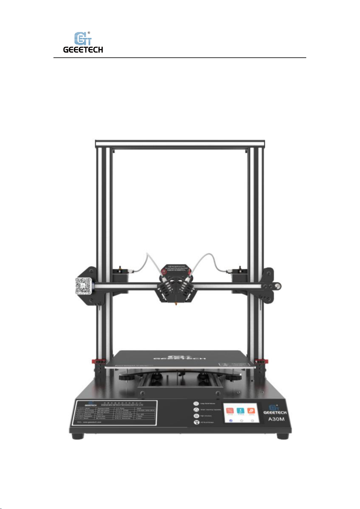
Geeetech A30M 3D Printer
User Manual(V1.00)
1
Page 2

Shenzhen Getech Technology Co.,Ltd
Content
1 Attentions ............................................................................................................................... 4
1.1 Safety Instructions ....................................................................................................... 4
1.2 Factory Test before Delivery ........................................................................................ 4
1.3 Risk statement ............................................................................................................. 4
2 Printing Parameters ................................................................................................................ 5
3 Packing list .............................................................................................................................. 6
4 Printer Display ........................................................................................................................ 7
5 Assembling ............................................................................................................................. 8
5.1 Main Frame Assembling .............................................................................................. 8
5.2 Wire connection .......................................................................................................... 9
5.3 Check the power input mode .................................................................................... 13
5.4 Load the filament ...................................................................................................... 13
6 First print .............................................................................................................................. 16
6.1 Leveling hot bed ........................................................................................................ 16
6.2 TF card printing ......................................................................................................... 18
7 Introduction of touch screen menu ..................................................................................... 20
7.1 Tree diagram.............................................................................................................. 20
7.2 Main Functions .......................................................................................................... 20
8 Software setting ................................................................................................................... 31
8.1 Install USB drivers ...................................................................................................... 31
8.2 Install slicing software ............................................................................................... 33
8.3 USB printing .............................................................................................................. 42
8.4 TF card printing ......................................................................................................... 48
9 Color Mixer ........................................................................................................................... 50
9.1 Download .................................................................................................................. 50
9.2 Introduction .............................................................................................................. 50
10 Function introduction......................................................................................................... 54
10.1 Power -resuming capability ..................................................................................... 54
10.2 Filament run-out sensor (optical)............................................................................ 54
10.3 3D Touch for auto bed leveling (Optical) ................................................................. 57
11 FAQ(Frequently Asked Questions) ...................................................................................... 58
11.1 Abnormal extrusion ................................................................................................. 58
11.2 The gear of the extruder skips and makes an abnormal noise ............................... 58
11.3 First layer abnormal ................................................................................................ 58
11.4 Layer shift ................................................................................................................ 58
11.5 Print stopped ........................................................................................................... 59
12 Declaration ......................................................................................................................... 59
12.1 Terms ....................................................................................................................... 59
12.2 Disclaimers .............................................................................................................. 59
2
Page 3

Shenzhen Getech Technology Co.,Ltd
Thank you for choosing Geeetech products!
[Important] Please read the instruction manual
carefully before using this machine.
Official site: https://www.geeetech.com/
Email us for technical support: https://www.geeetech.com/contact_us.htm
Facebook Group:
3
Page 4

Shenzhen Getech Technology Co.,Ltd
1Attentions
1.1Safety Instructions
1) Please switch to the correct local voltage (115V-230V) before turning on the printer. Be sure
the switch is in the correct position or it will damage the power supply unit (PSU).
2) Be sure all wires are correctly connected before turning on the printer.
3) Don’t touch extruder head or hot bed when printing as they generate high temperature
which may cause burn.
4) Don’t leave the printer unattended when printing.
1.2Factory Test before Delivery
To ensure quality, each printer is tested at the factory. As a result, there may be filament residue
in the extruder head or on the hot bed, but it should not affect normal use. We provide the spare
nozzle in the accessory kit just in case.
1.3 Risk statement
1) Before color mixing or monochrome printing, make sure that there is the filament in the
feeding tube on both sides of the extruder head to prevent back flushing of the molten
filament inside the extruder head, resulting in clogging.
2) Make sure there is filament in feeding tubes on the both side of extruder head even using a
single-sided extruder for monochrome printing, moreover the filament in the other feeding
tube cannot be pulled out during the printing process.
3) Please do not disassemble the printer without permission. If there is any problem, please
contact the after-sales service.
4
Page 5

Shenzhen Getech Technology Co.,Ltd
2 Printing Parameters
1) Printing Parameters
Printing technology: FDM
Printing volume: 320*320*420mm3
Printing accuracy: 0.1~0.2mm
Position precision: X/Y: 0.011mm Z: 0.0025mm
Printing speed: 60mm/s
Nozzle quantity: 2-in-1-out single nozzle
Nozzle diameter: 0.4mm
Filament: diameter 1.75mm; ABS/ PLA, etc.
Environment temperature: 10℃-40℃
Operating system: Windows/Mac/Linux
Slicing software: Repetier-Host, EasyPrint 3D, Cura
File format: .gcode
2) Electrical Parameter
Power input: 100~120V/200~240V
Power output: DC24V/18.8A, 450W
Connectivity: TF card, USB
Touch screen: 3.2 -Inch Full-color Touch Screen
3) Mechanical Parameter
Printer size: 508x545x657 mm
Package size: 670x560x320 mm3
Net weight: 13.8kg
Gross weight: 20.5kg
3
5
Page 6
Shenzhen Getech Technology Co.,Ltd
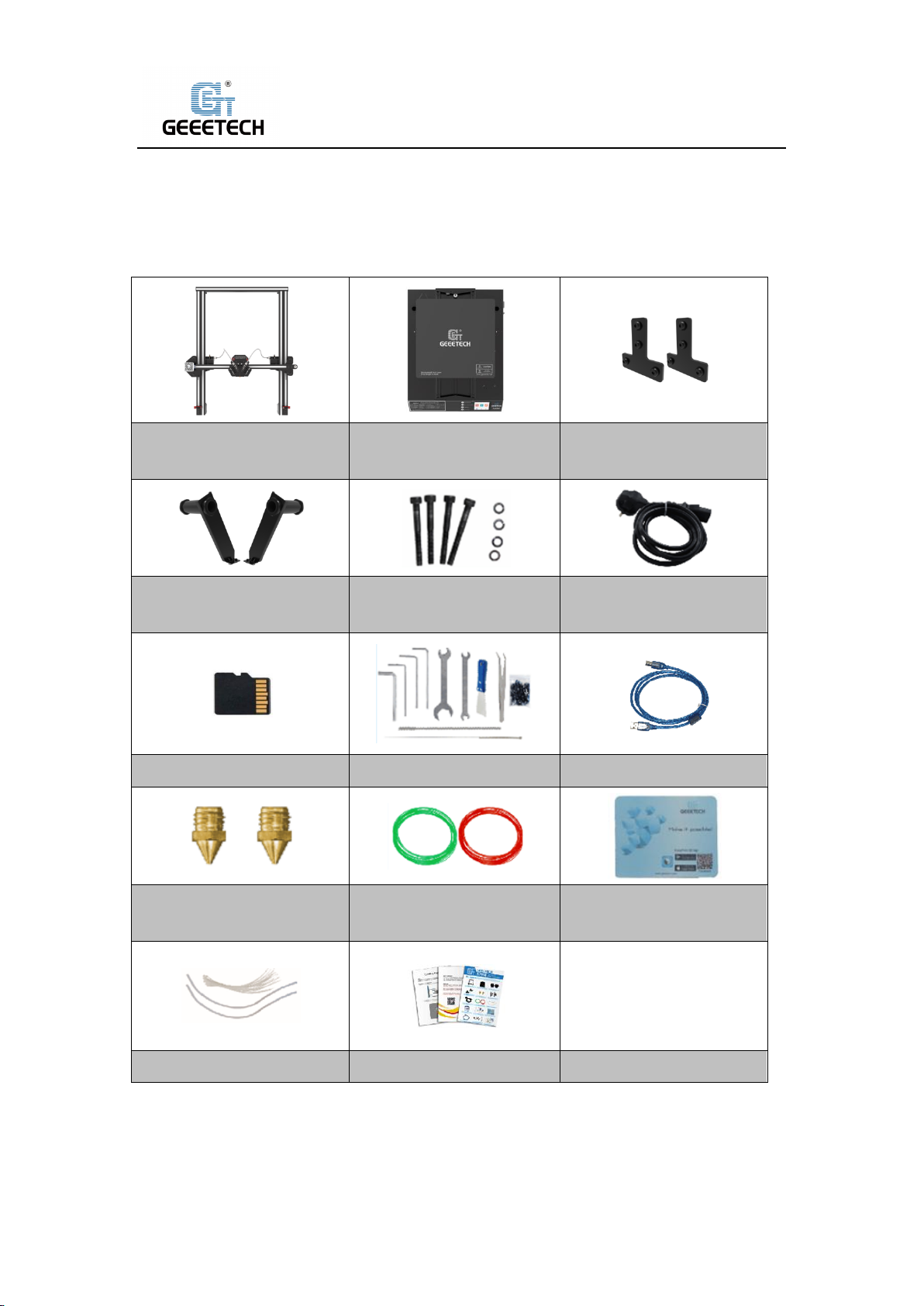
Gantry kit
Bottom kit
T-shaped plate component
(2 sets)
Spool holder component
(2 sets)
Gantry and base
installing screws
Power cord
TF Card
Tool kit
USB cable
Nozzles *2
Filaments(2 random
colors)
Mouse pad
Teflon tube & Zip ties
User guide
3 Packing list
Please check the parts/accessories when you receive the printer (As shown below). If any
spare parts are missing, please contact your sales representative.
6
Page 7
Shenzhen Getech Technology Co.,Ltd
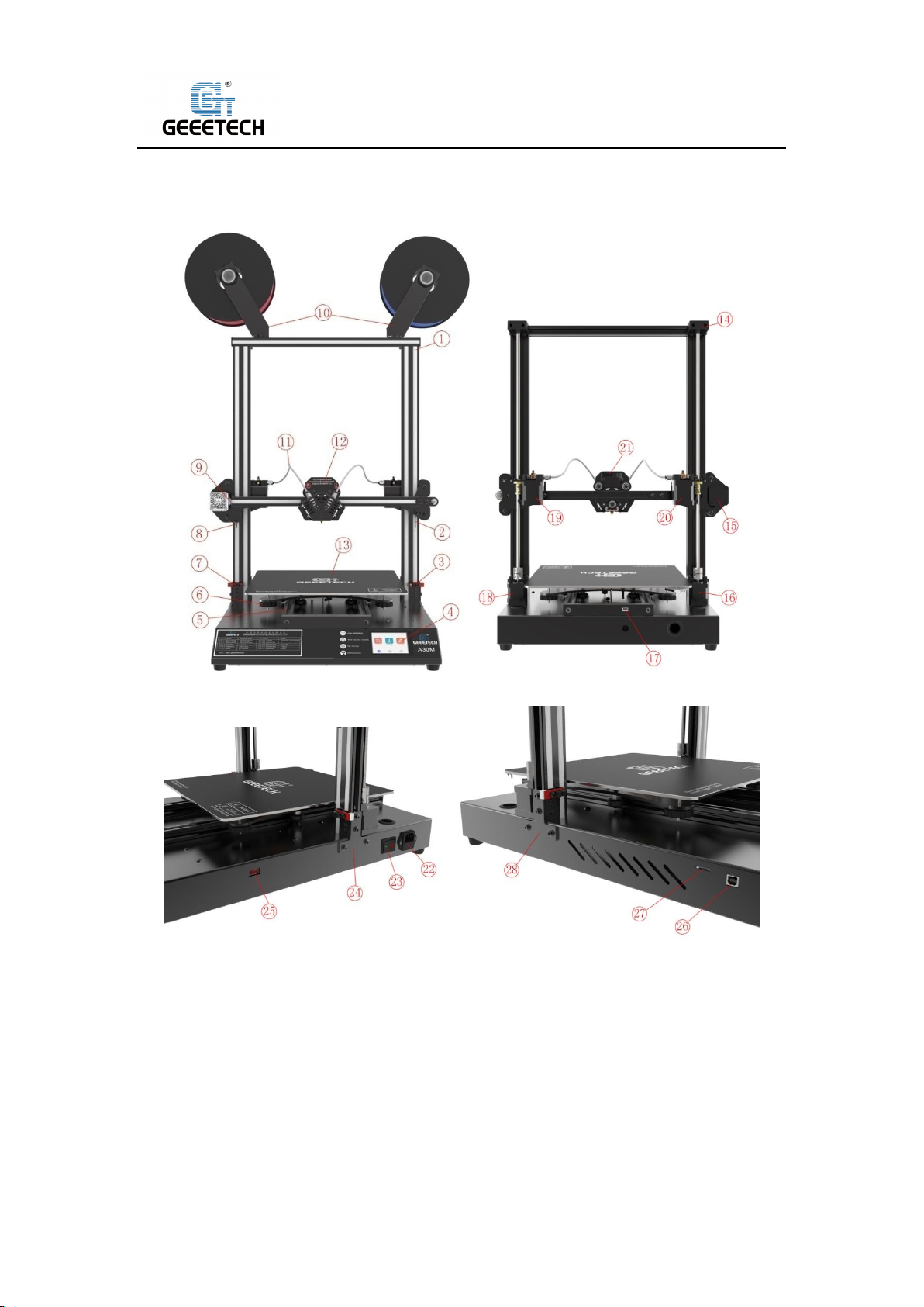
4 Printer Display
(Picture 4-1) (Picture 4-2)
(Picture 4-3) (Picture 4-4)
○1Gantry frame;② Right limit switch plate;③ Right photoelectric limit switch;④ Touch screen;
⑤Y axis;⑥Hot bed height adjusting nuts;⑦Left photoelectric limit switch;⑧Left limit switch
plate;⑨ X axis limit switch;⑩ Spool holder;⑪Teflon feeding tube(Bowden tube);⑫Extruder
head;⑬Hot bed;⑭Z axis top assembly;⑮X axis motor;⑯Z axis motor Z1;⑰Y axis limit
switch;⑱Z axis motor Z2;⑲Extruder E1;⑳Extruder E0;㉑Extruder socket;㉒Power socket;
㉓Power switch;㉔Right T-shaped plate;㉕Power voltage selector switch;㉖USB port;㉗TF card
slot;㉘Left T-shaped plate
7
Page 8
Shenzhen Getech Technology Co.,Ltd
Gantry kit
Bottom kit
T-shaped plate component
(2 sets)
Spool holder component
(2 sets)
Gantry and base
installing screws
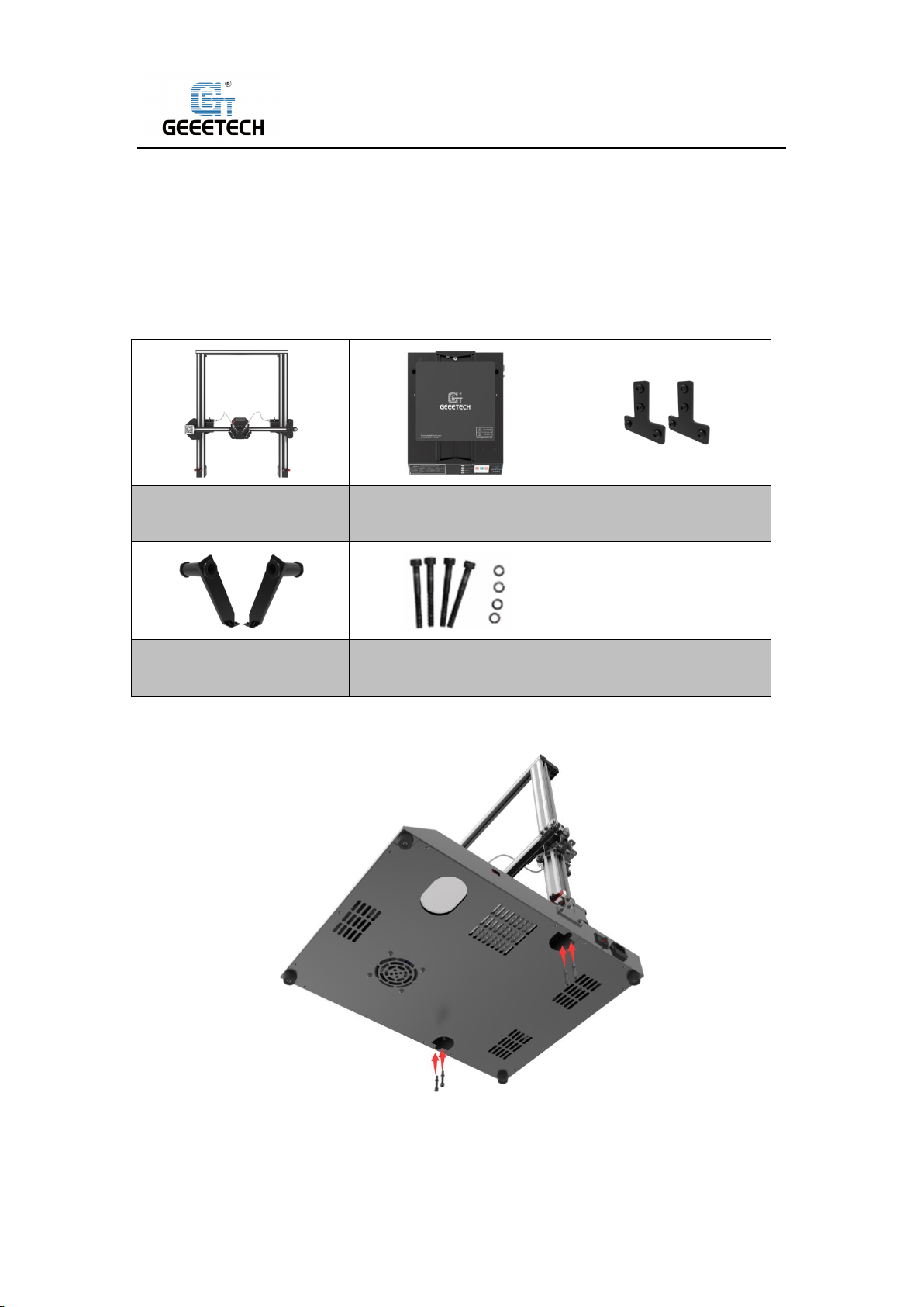
5 Assembling
5.1Main Frame Assembling
Main frame consists of gantry kit and base, T- shaped plate, spool holder and screws.
1) Assemble the gantry frame and base from bottom with 4 M5x30 screws and 4 spring
washersM5 as shown in picture (5-1).
(Picture 5-1)
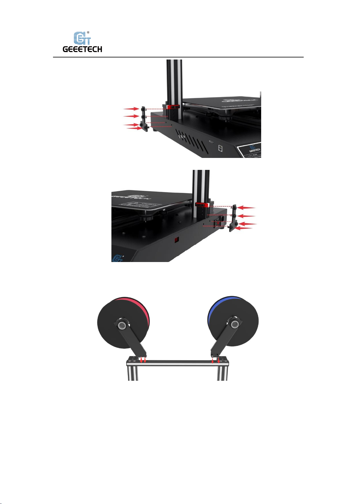
2) Fix the gantry frame and base with T-shaped plates. See picture (5-2, 5-3).
8
Page 9
Shenzhen Getech Technology Co.,Ltd
(Picture 5-2)
(Picture 5-3)
3) Assemble filament spool holders and attach to the top of the frame, with 2pcs M3x6 screws
and 2 T- nuts M3, as shown picture (5-4).
(Picture 5-4)
5.2Wire connection
1) Insert two Teflon tubes into the quick-insert connector of the two extruders as shown in
picture (5-5).
9
Page 10

Shenzhen Getech Technology Co.,Ltd
(Picture 5-5)
2) Plug extruder wire into molex socket. Be sure plug is firmly seated into socket. See picture
(5-6).
(Picture 5-6)
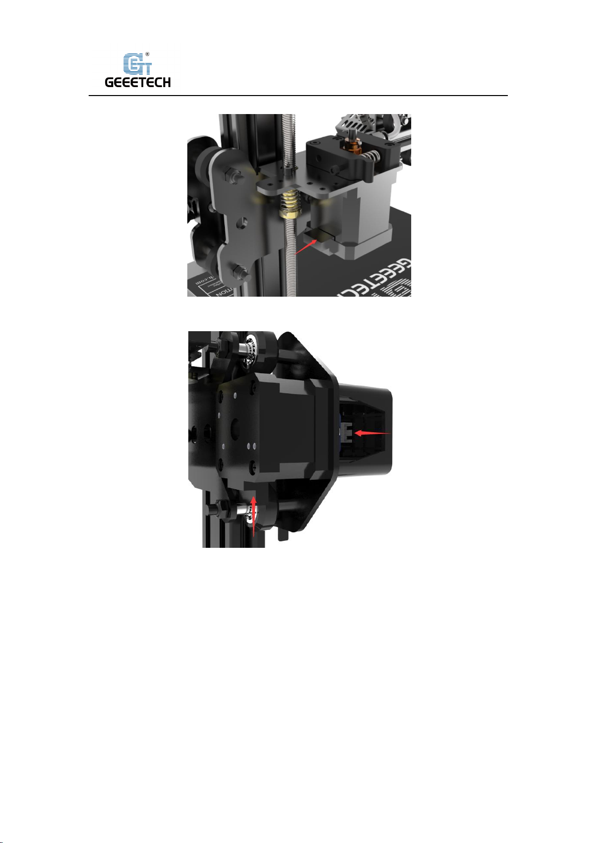
3) Connect extruder motor wires of E0.See picture (5-7).
(Picture 5-7)
4) Connect extruder motor wires of E1.See picture (5-8).
10
Page 11
Shenzhen Getech Technology Co.,Ltd
(Picture 5-8)
5) Connect the wires of X axis motor and limit switch. See picture (5-9).
(Picture 5-9)
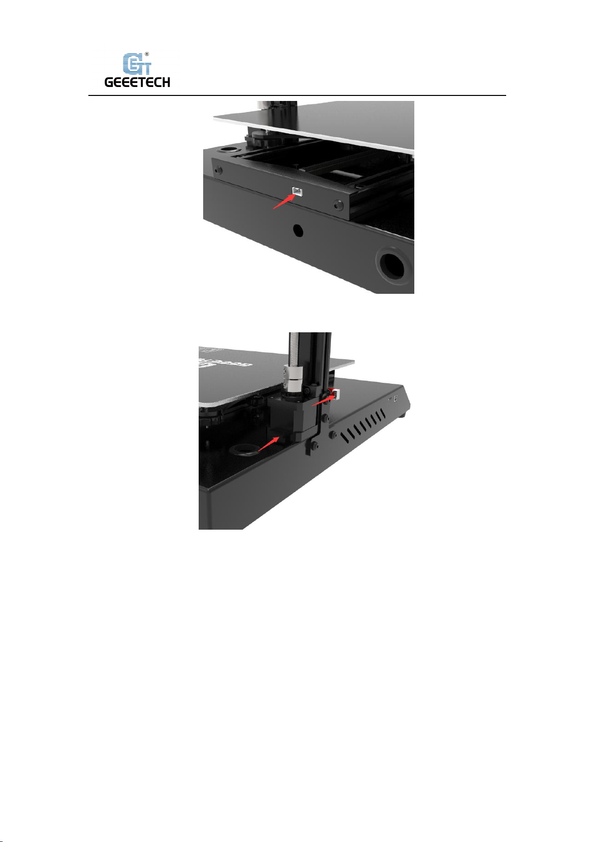
6) Connect the wires of Y axis limit switch. See picture (5-10).
11
Page 12
Shenzhen Getech Technology Co.,Ltd
(Picture 5-10)
7) Connect the Z1 axis motor and the Z1 axis limit switch wire. See picture (5-11).
(Picture 5-11)
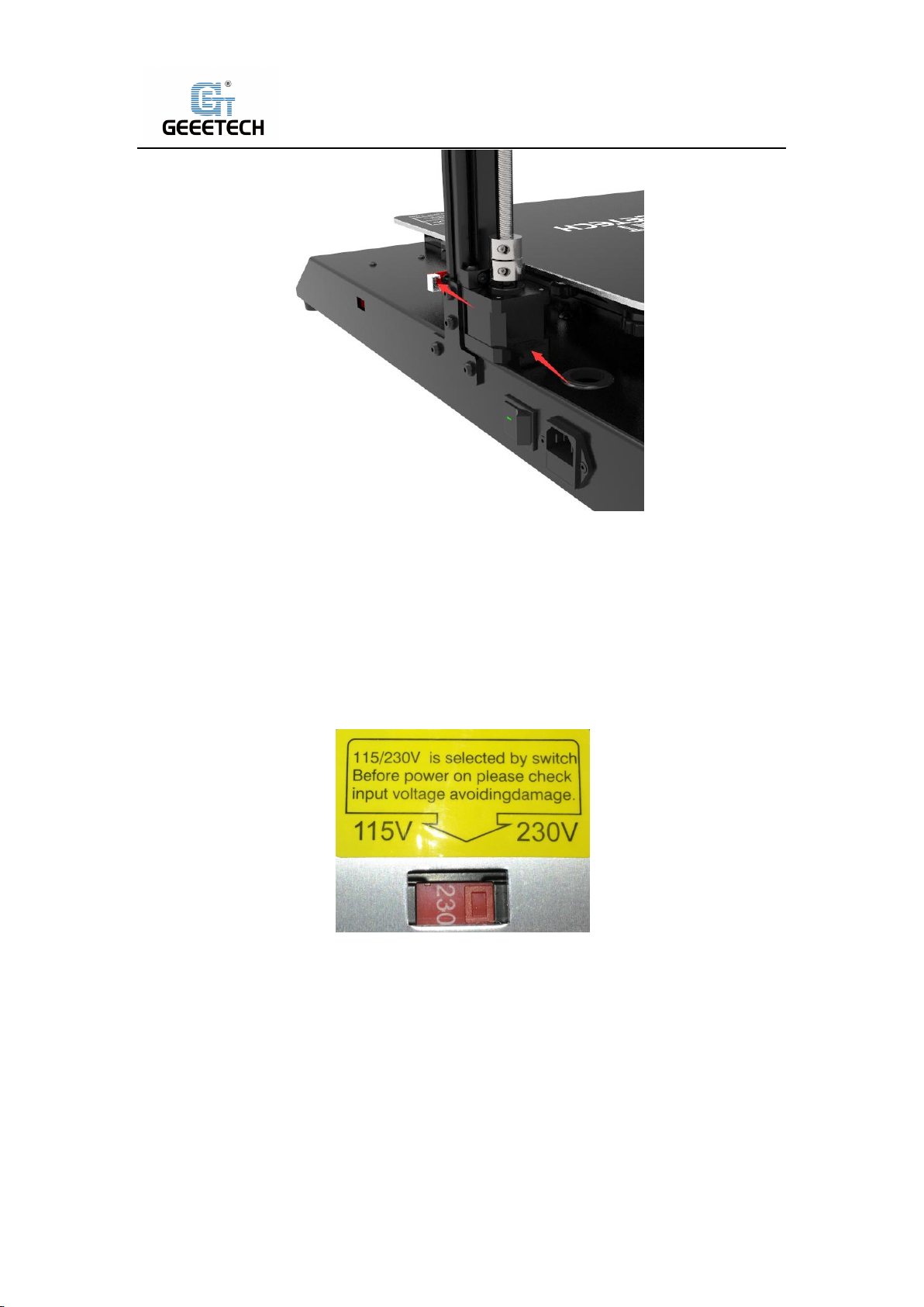
8) Connect the Z2 axis motor and the Z2 axis limit switch wire. See picture (5-12).
12
Page 13
Shenzhen Getech Technology Co.,Ltd
(Picture 5-12)
5.3Check the power input mode
The factory default voltage is 230V, please choose the correct voltage according to your local
voltage standard. See picture (5-13).
Note: Be sure the switch is set for the correct voltage.
(Picture 5-13)
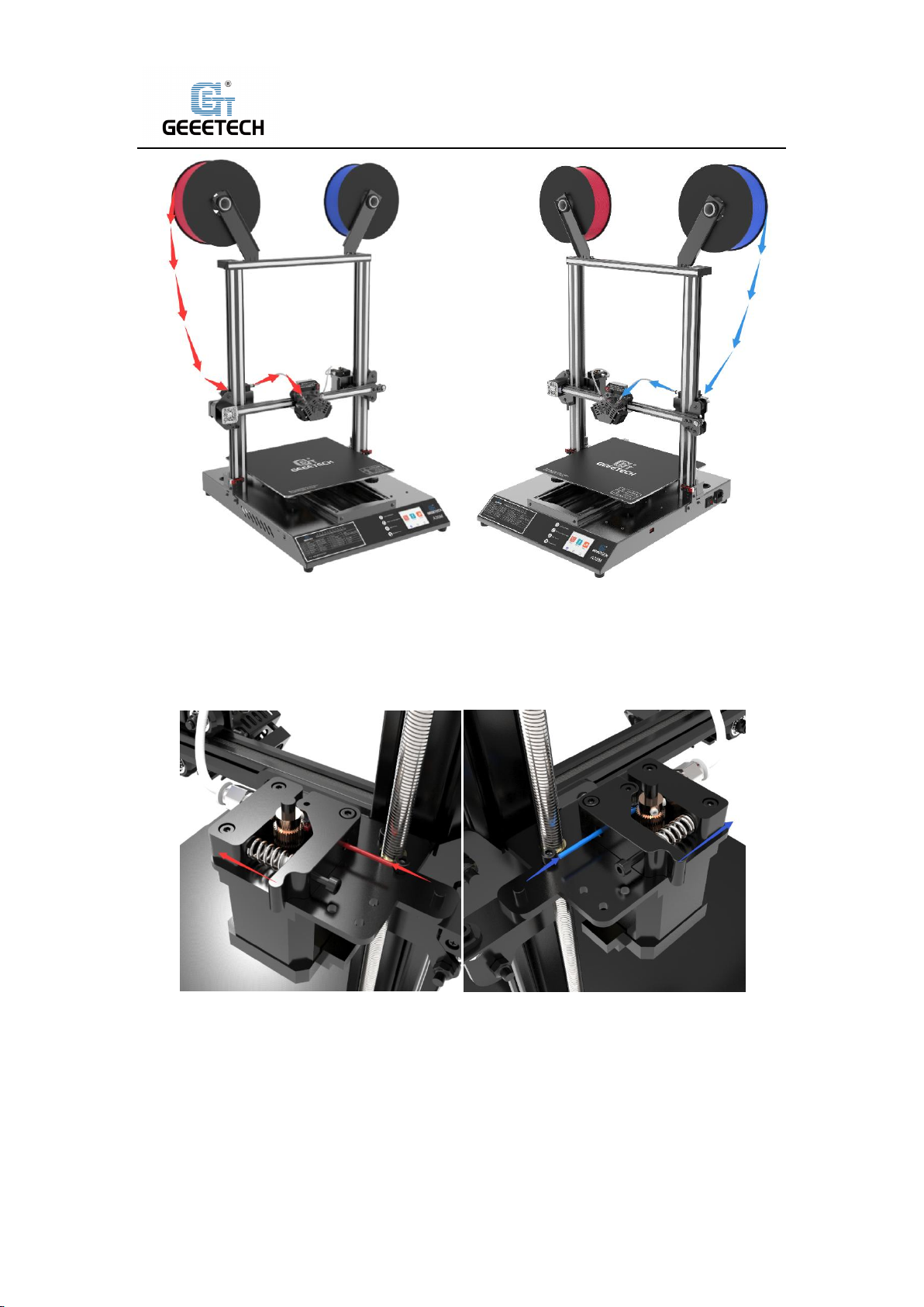
5.4Load the filament
Put filament on spool holder, please pay attention to the feeding direction of the filament. See
picture (5-14), (5-15).
13
Page 14
Shenzhen Getech Technology Co.,Ltd
(Picture 5-14) (Picture 5-15)
Filament is bent, therefore it needs to be straightened by your hands and trimmed to make it
easier to insert filament into feeder. Press down the lever handle of the extruder and insert the
filament into the feeding tube until it reaches extruder head. Extruder E0, E1 with arrow shown
in picture (5-16),(5-17).
(Picture 5-16) (Picture 5-17)
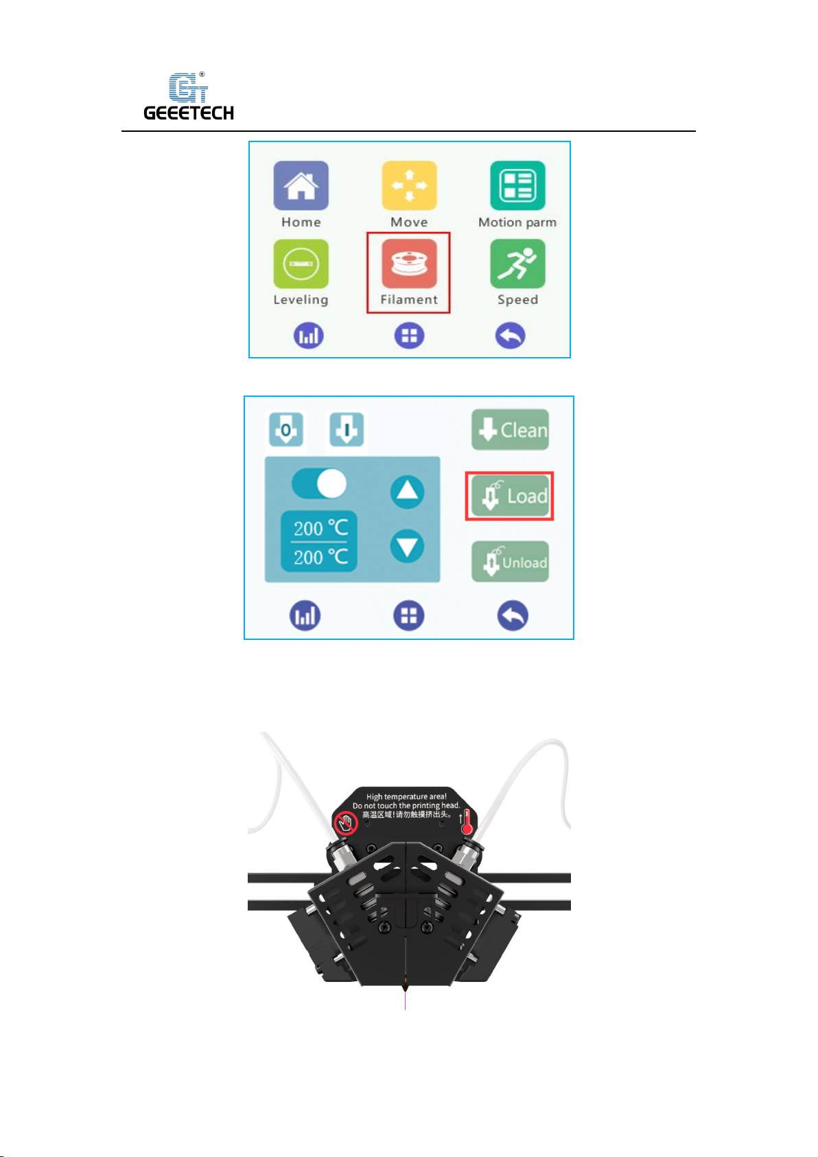
Please set the target temperature of nozzle about 190-210℃ when printing PLA. Control the
extruder feeding on touch screen after the nozzle temperature is stable. See picture
(5-18),(5-19).The extruder will feed automatically until the nozzle material is flowing. Please
select extruder E0, E1 in turn.
14
Page 15
Shenzhen Getech Technology Co.,Ltd
(Picture 5-18)
(Picture 5-19)
Please observe the nozzle , to be sure there is no filament stuck,and that filament is coming out
smoothly and switching the colors of filament smoothly. Then stop filament feeding and clear the
nozzle with tweezers. See picture (5-20).
(Picture 5-20)
15
Page 16
Shenzhen Getech Technology Co.,Ltd
6First print
6.1Leveling hot bed
The first layer is the key to a successfully printed model, which would directly affect the quality of
printing model and achieve a good bed adhesion. In order to avoid scratching nozzle and hot bed,
the factory default setting is a little high. Users need to level the hot bed and set the distance
between the nozzle and hot bed before printing. After the first-time bed leveling, users don’t
need to level the bed again. Details as follows:
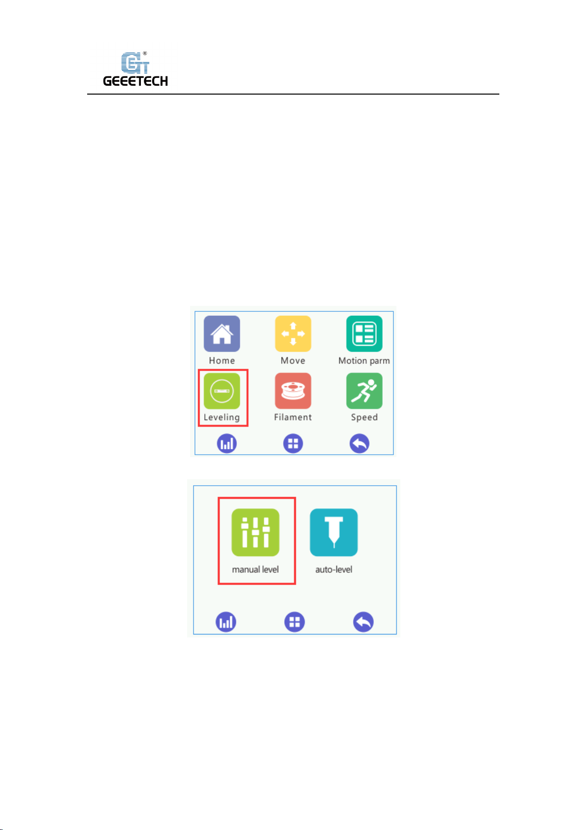
1) Rough leveling
Please click the “Home” to enter “Leveling” interface on the touch screen. See picture (6-1). If
you click “manual level”, it shows “manual level” interface shown as picture (6-2).
(Picture 6-1)
(Picture 6-2)
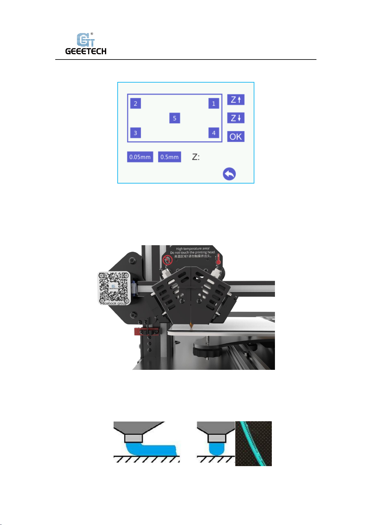
Put a piece of leveling paper or A4 paper between hot bed and nozzle, Click the middle "5"
button, and select the appropriate precision (0.05mm/0.5mm) in the lower left corner to adjust
the height deviation value in the Z-axis direction until the distance between the platform and the
nozzle is about one sheet of paper. The thickness can be about 0.1~0.2mm, Slide the paper back
and forth to see if you feel a slight resistance. If yes, it means that extruder head is in the right
16
Page 17
Shenzhen Getech Technology Co.,Ltd
place. See picture (6-3). After adjusting the height at position “5”, click “OK” to save current
value.
(Picture 6-3)
Please click the button in order from 1-4, At each corner, use the adjusting nuts under the bed to
set the distance between nozzle and hot bed to about the thickness of a piece of paper (Slide the
paper back and forth to see if you feel a slight resistance). Now rough leveling is finished. See
picture (6-4).
(Picture 6-4)
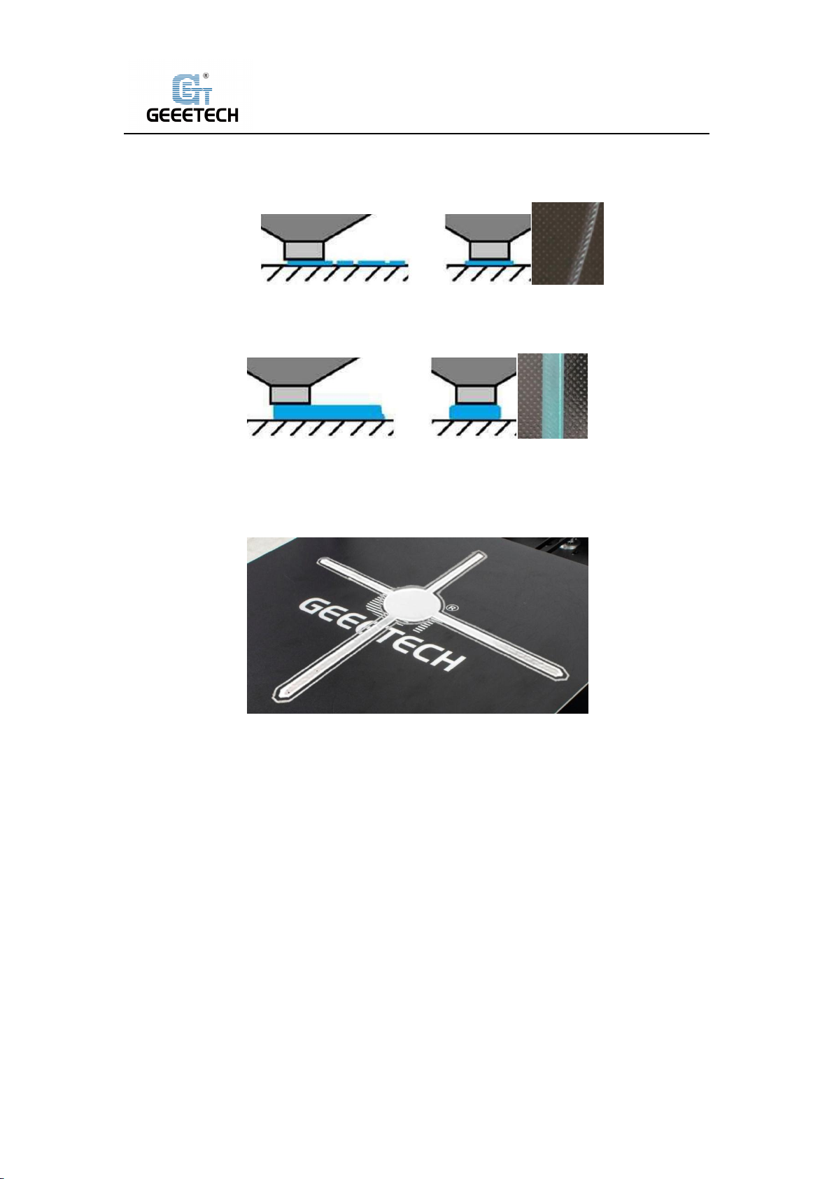
1) Accurate leveling
If you level hot bed with A4 paper, the first layer might be too high, too low or moderate.
a. Too high: If the distance between nozzle and hot bed is too far, filament will not stick to the
bed well. See picture (6-5).
(Picture 6-5)
17
Page 18
Shenzhen Getech Technology Co.,Ltd
b. Too low: If the distance between nozzle and hot bed is too close, it prevents filament from
coming out, causes the extruder gear to click or grind on filament and even worse, it would
scratch nozzle and hot bed. See picture (6-6).
(Picture 6-6)
c. Moderate: Extrude filament properly and evenly. Stick to the hot bed. See picture (6-7).
(Picture 6-7)
In case of too high and too low, please adjust knobs under the hotbed slightly until you achieve
proper height. It may take some trial and error to achieve the best result. An example of good
first layer, see picture (6-8).
(Picture 6-8)
Note:
1) Be sure to adjust the height at center point (position5) on the touch screen, after clicking
“OK” to save its data, you can use then knobs to adjust the hot bed at the 4 corners.
2) When viewed from the above, turning the knobs clockwise, the hot bed will rise, and vice
versa.
3) Avoid the nozzle touching the bed; use a piece of A4 paper. Or it will scratch the bed.
6.2TF card printing
Insert TF card into the slot. See picture (6-9).
18
Page 19

Shenzhen Getech Technology Co.,Ltd
(Picture 6-9)
Click “Printing” on touch screen to enter Print model menu. See picture (6-10).
(Picture 6-10)
Click on the in-built.Gco file in the TF card, Click the “Print” button. See picture (6-11), the
machine will automatically start printing, as shown in picture (6-12) and picture (6-13).
(Picture 6-11)
19
Page 20
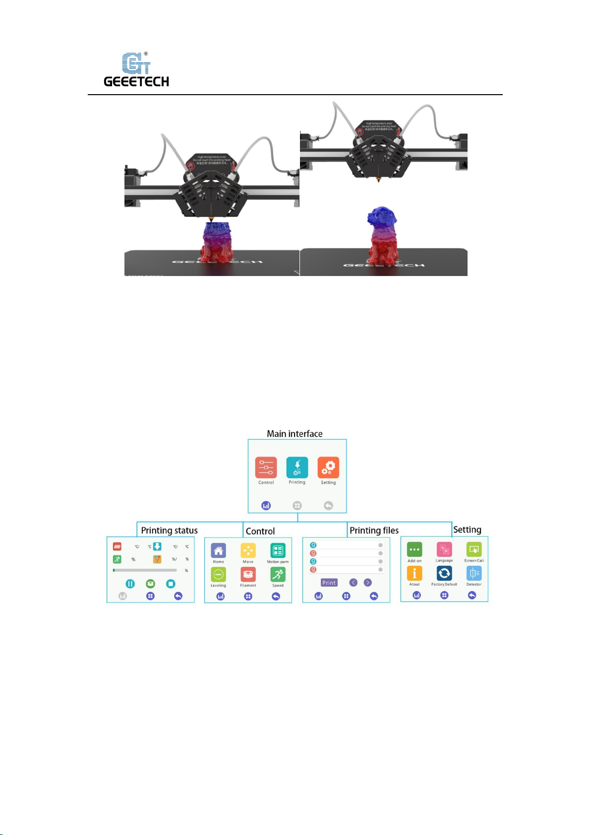
Shenzhen Getech Technology Co.,Ltd
(Picture 6-12) (Picture 6-13)
7Introduction of touch screen menu
7.1Tree diagram
7.2Main Functions
(Picture 7-1)
7.2.1 Main interface:
20
Page 21

Shenzhen Getech Technology Co.,Ltd
7.2.2Print status Interface:
(Picture 7-2)
(Picture 7-3)
Two submenus
1) Click the hot bed temperature/extruder head temperature/speed to enter the interface of
temperature and speed. See picture (7-4).
21
Page 22

Shenzhen Getech Technology Co.,Ltd
(Picture 7-4)
2) Click the “Fixed ratio mixer “to enter the interface of mixer setting, see picture (7-5).
(Picture 7-5)
The fixed scale of mixer and specified scale change or position mixer are not available to open at
the same time, either-or.
The fixed scale of mixer : Please check the feeding scale of Extruder E0 and E1 when adjust
printing, which could achieve the effect of mixed two-color printing.
Specified scale change or position mixer: Please adjust extruder feeding percentage and
corresponding height according to the direction of start /end, which can gradient from one color
to another in one height.
7.2.3Main functions of control menu:
22
Page 23

Shenzhen Getech Technology Co.,Ltd
(Picture 7-6)
Six submenus at Control menu homepage
1) Click “Home” to its interface, see picture (7-7).
(Picture 7-7)
2) Click “Move” to its interface, see picture (7-8).
23
Page 24

Shenzhen Getech Technology Co.,Ltd
(Picture 7-8)
Please choose its precision firstly before moving axes. There are
“30/10/1/0.5/0.1mm”available.And control every axis moving. Moreover, when the lower
right-hand corner motor status is in the "Enable" state, motor is locked. When “Disable” releases,
motor is unlocked, you can move every axis by hand.
3) Click “Motion Parameter”, it will enter motion parameter interface. See picture (7-9).
(Picture 7-9)
This page only displays every motion parameter, if no special condition, it doesn’t to modify.
4) Click “Leveling “to its interface.(7-10).
24
Page 25

Shenzhen Getech Technology Co.,Ltd
(Picture 7-10)
Two submenus at leveling interface
a. Click “manual level “to its interface. See picture (7-11).
(Picture 7-11)
Please choose its precision firstly before manual leveling. You can choose“0.05/0.5mm”. Then
adjust z axis height according to the actual situation. And click “Ok” to save its settings.
B. Click “auto level” to its interface. See picture (7-12).
25
Page 26

Shenzhen Getech Technology Co.,Ltd
(Picture 7-12)
First, you need to select the type of auto leveling, 3D Touch or CAS. Click the bottom icon to
select and then click the upper switch to turn on the auto leveling function. If you choose “3D
Touch”, click “Push-pin up/Push-pin down” and “Alarm Release” to test whether the 3D Touch
function is normal before leveling.
And click the “Measure “icon, when the extruder head has moved to the center measure
position, click “Offset Interval“to select the appropriate offset accuracy, and adjust the difference
of height to set a available range between the bottom of 3D Touch pin and nozzle. And then click
“Save”, the parameter of auto leveling is finished.
5) Click “Filament” to its interface. See picture (7-13).
(Picture 7-13)
A30M has 2 extruders; therefore it can control feeding in and out and heat operation of E0 and
E1.
Clean filament:
Please keep clean to extruder head in order to have long printing time. Avoid plugging, we
suggest keep clean on a regular basis. Click its button, Extruder E0 and E1 will cycle alternately of
feeding to achieve cleaning.
6) Click “Speed” to its interface. See picture (7-14).
26
Page 27

Shenzhen Getech Technology Co.,Ltd
7.2.4 Interface of printing list:
(Picture 7-14)
(Picture 7-15)
Please choose the model file at printing file list, and click “Print “and then start printing.
7.2.5 Interface of setting:
27
Page 28
Shenzhen Getech Technology Co.,Ltd
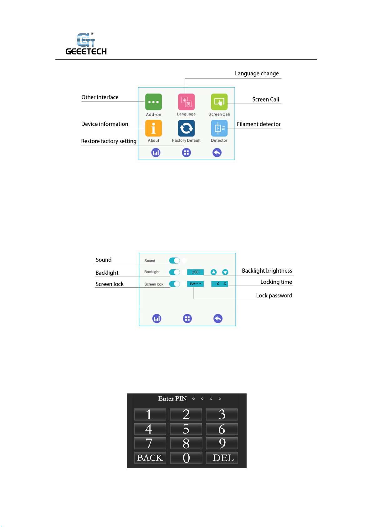
(Picture 7-16)
Six submenus at setting interface
1) Click “Add-on” to enter its interface. See picture (7-17).
(Picture 7-17)
After the screen lock button is turned on, the machine screen will enter the lock screen of Picture
(7-18) after the set lock time to prevent others from operating the machine by mistake. The
factory default is off, and the initial password is: “0000”.
(Picture 7-18)
28
Page 29

Shenzhen Getech Technology Co.,Ltd
After resetting the password, if you forget the password, you can connect the machine to the
computer and modify it with the PC software. As shown in Picture (7-19), after the machine is
connected to the computer, enter "M2139 P2 W *" in the G-Code command input box of the
manual control page on the right side of the software. (Note: **** in this command is the reset
4-digit password)
(Picture 7-19)
2) Click “Language” to its interface. See picture (7-20).
(Picture 7-20)
3) Click “Screen Cali” to its interface. See picture. (7-21).
29
Page 30

Shenzhen Getech Technology Co.,Ltd
(Picture 7-21)
4) Click “About” to the device information. See picture (7-22).
(Picture 7-22)
5) If you click “Yes”, it will restore factory settings. See picture (7-23).
(Picture 7-23)
6) Click “Detector “to its interface. See picture (7-24).
30
Page 31

Shenzhen Getech Technology Co.,Ltd
(Picture 7-24)
There is no display at printing interface if no opening. Only printing interface opens, it shows
filament. When the picture is green, it can test filament. When the picture is red, it cannot test
filament. See picture (7-25), (7-26).
(Picture 7-25) (Picture 7-26)
8Software setting
8.1Install USB drivers
Two printing choices of A30M: TF card printing and USB printing.
TF card printing:
Insert TF card into the slot after leveling, and choose a .gcode file to start printing. No USB driver
is required.
USB printing:
Connect the printer and computer with a USB cable to control printer with slicing software such
as Repetier-Host. Because of some unstable factors such as signal interference, the USB printing
prone to fail. So we suggest choosing TF card printing.
Details of USB printing are as follows:
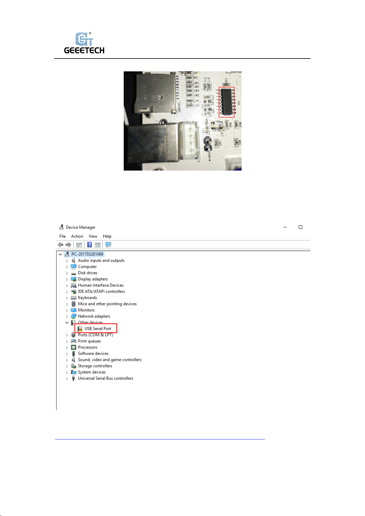
Firstly, turn on the printer, and connect the printer to computer with a USB cable. Normally, the
computer will automatically search the install drive. The newest communication chip of A30M is
CH340. See picture (8-1).
31
Page 32
Shenzhen Getech Technology Co.,Ltd
(Picture 8-1)
Check whether the driver is automatically installed successfully or not. Click to choose “My
computer>Property>Device manager”.
If it shows the exclamation mark as picture below (8-2), then you need manually install the driver.
(Picture 8-2)
Download link for CH340:
https://www.geeetech.com/index.php?main_page=download&download_id=40
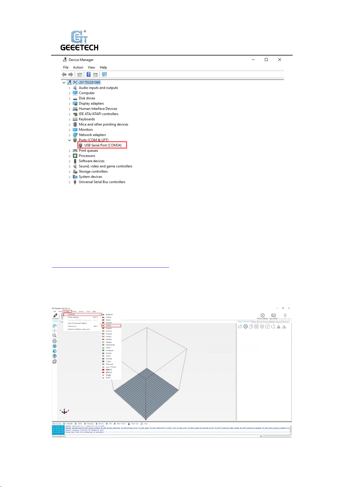
After the driver is installed, check the “Device manager” and see if it is same as the picture below
(8-3). If so, it means the driver is successfully installed.
32
Page 33
Shenzhen Getech Technology Co.,Ltd
(Picture 8-3)
8.2Install slicing software
Repetier-Host is the default slicing software here. Download address:
https://www.repetier.com/download-software/)
1) Set printer parameter
When Repetier-Host is installed, turn on the printer and open the Repetier-Host. Repetier-Host
supports several languages. You can choose your native language from Config>Language (Picture
8-4 for details).
33
Page 34
Shenzhen Getech Technology Co.,Ltd
(Picture 8-4)
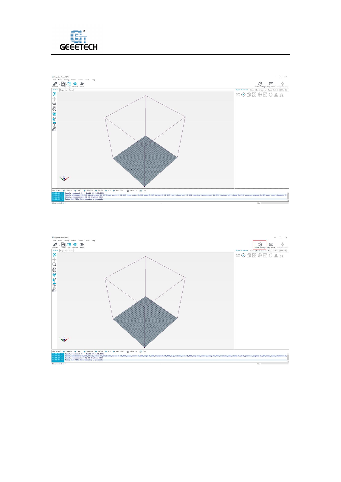
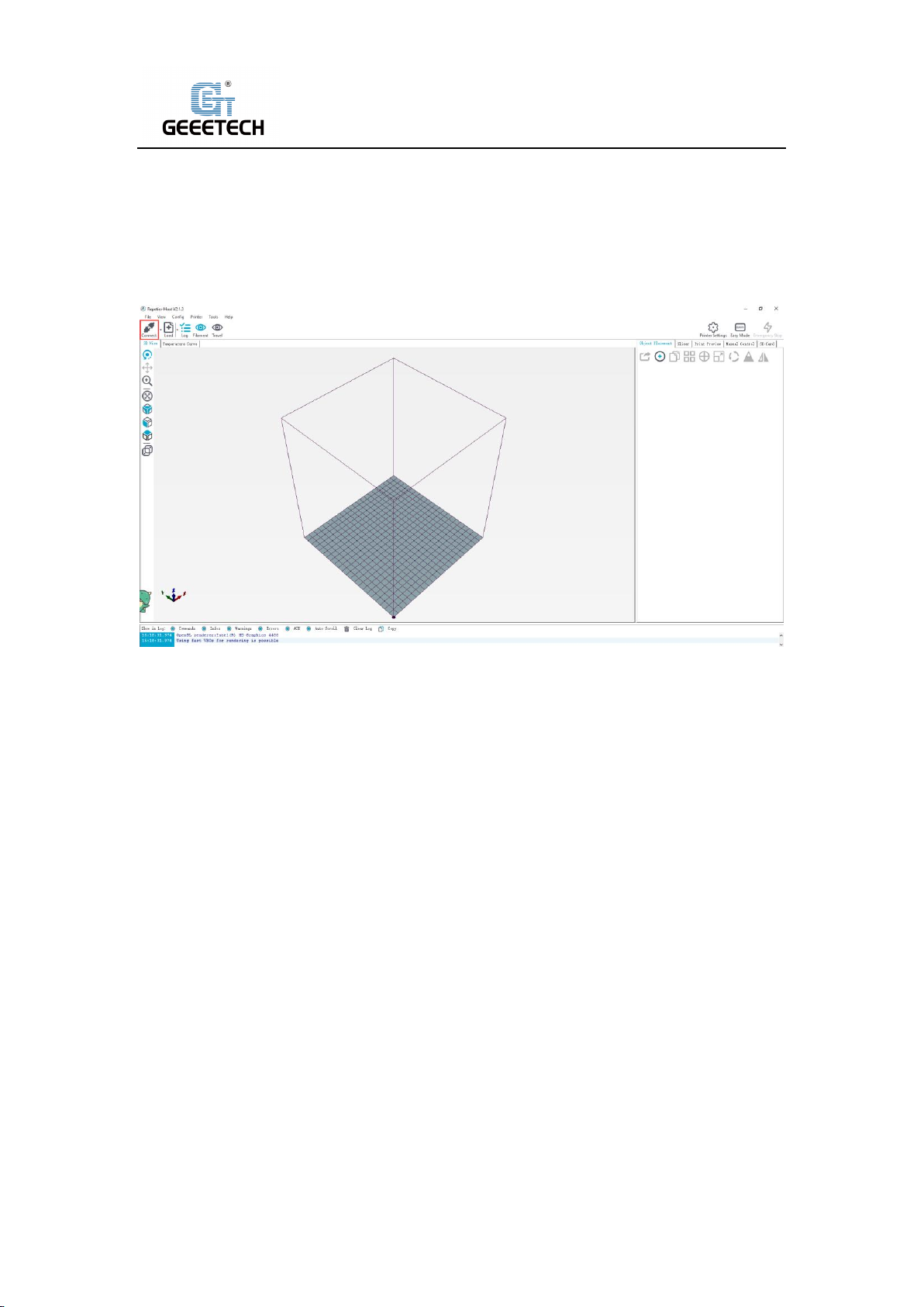
English interface as picture (8-5):
(Picture 8-5)
Using the Repetier-Host for the first time, printer parameters need to be configured before
connecting. Click “Printer settings” on the top right corner, see picture (8-6).
(Picture 8-6)
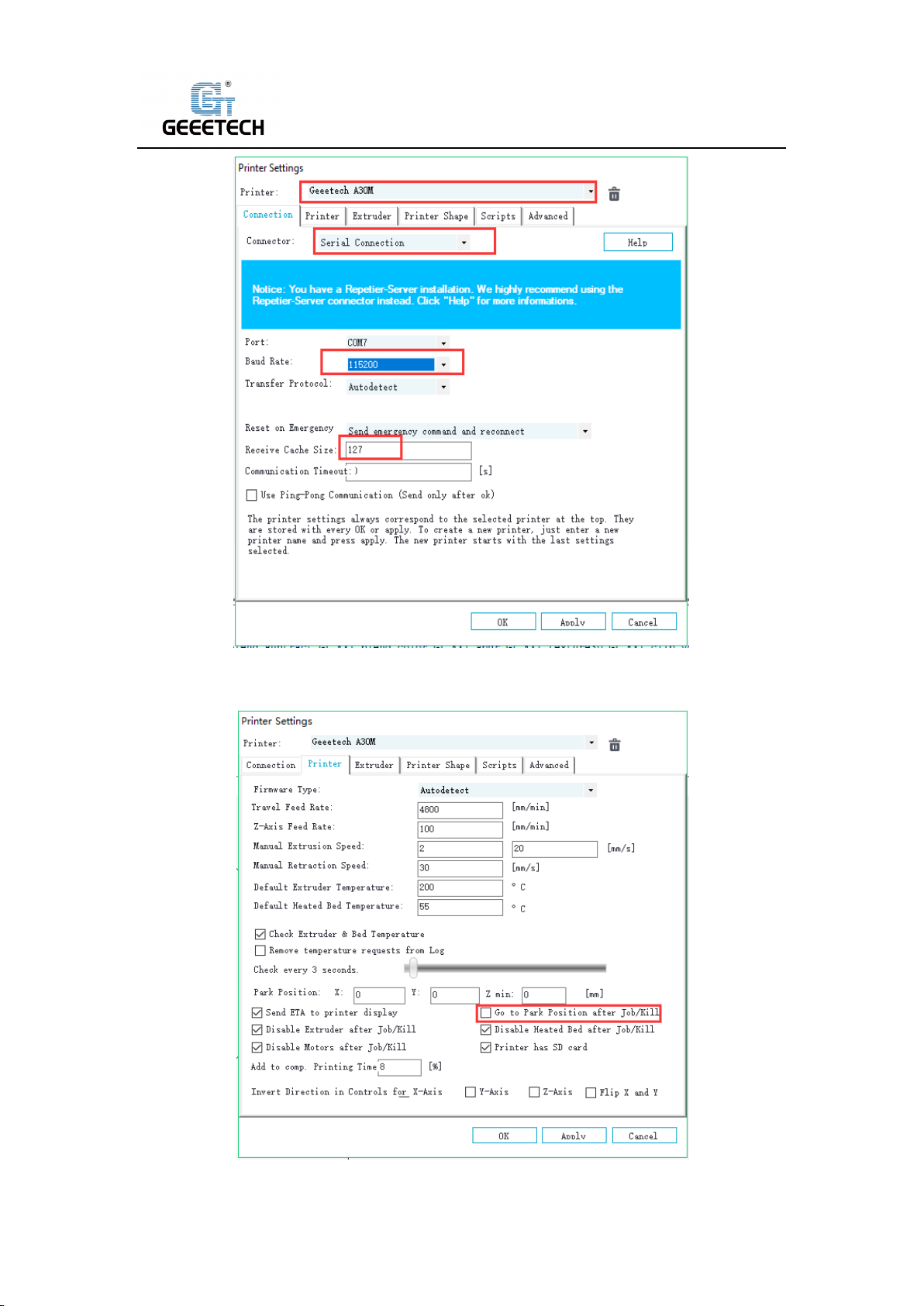
It pops up the content as the picture below (8-7). Write down the relevant info accordingly.
(Pay attention to the highlighted parts).
a. Connection dialog:see picture (8-7)
34
Page 35
Shenzhen Getech Technology Co.,Ltd
b. Printer dialog(Picture 8-8)
(Picture 8-7)
(Picture 8-8)
35
Page 36
Shenzhen Getech Technology Co.,Ltd
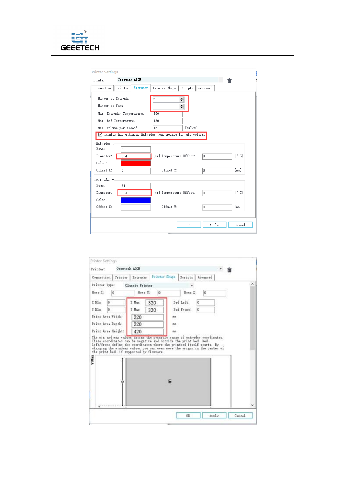
c. Extruder dialog(Picture 8-9)
d. Printer shape dialog(Picture 8-10)
(Picture 8-9)
(Picture 8-10)
Now the printer parameters are set.
36
Page 37
Shenzhen Getech Technology Co.,Ltd
Note: The baud rate is still 115200, Mac OS, Repetier Host are the same.
2) Setting slicing parameter
After setting the printer parameters, click “Connect” on the top left corner. The color of the icon
changed to green means the printer connects to the Repetier-Host successfully. Click it again to
“Disconnect”. See picture (8-11).
(Picture 8-11)
After successfully connected, choose “Slicer> CuraEngine” and open the configuration menu. See
picture (8-12).
37
Page 38

Shenzhen Getech Technology Co.,Ltd
It pops up dialog as picture below (8-13):
(Picture 8-12)
(Picture 8-13)
Printer parameters are important to print quality. Customers need to run tests to find the best
parameters for their printers. Here we provide a configuration file for your reference (“Geeetech
A30M PLA high.rcp”). You can import it according to the steps as follows. The following is an
example of parameters for PLA (Picture 8-14):
38
Page 39

Shenzhen Getech Technology Co.,Ltd
Click “Print>Import”
(Picture 8-14)
It pops up the dialog as below. See picture (8-15). Choose “Geeetech A30M PLA high.rcp” and
open it.
(Picture 8-15)
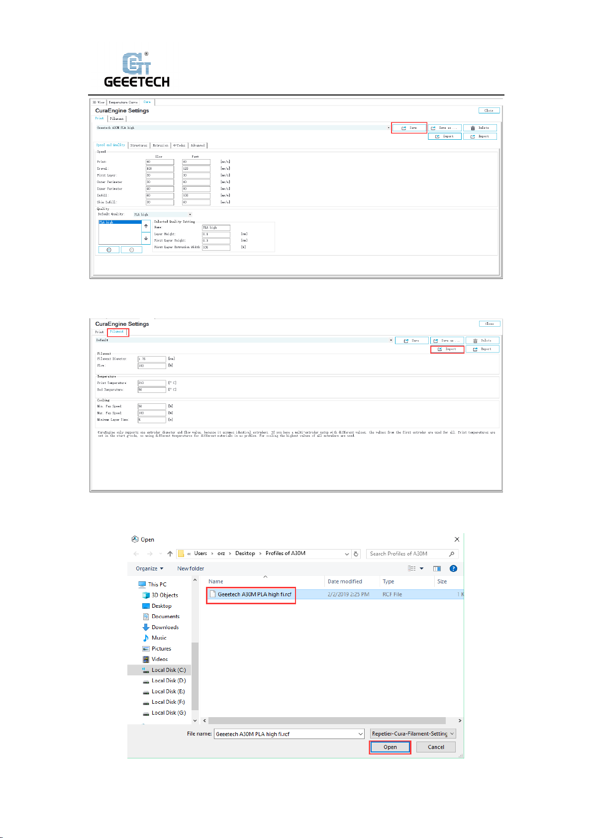
Now, the configuration file is imported, click “Save”. See picture (8-16).
39
Page 40
Shenzhen Getech Technology Co.,Ltd
(Picture 8-16)
Click “Filament”>“Import”. See picture (8-17).
(Picture 8-17)
It pops up dialog as below (Picture 8-18); choose “Geeetech A30M PLA high fi.rcf”and open it.
40
Page 41

Shenzhen Getech Technology Co.,Ltd
(Picture 8-18)
Now, the configuration file is imported. Click “Save”. See picture (8-19).
(Picture 8-19)
Choose “Geeetech A30M PLA high “as print configuration and “Geeetech A30M PLA high fi” as
printing material setting. Details see picture (8-20) below.
(Picture 8-20)
Now parameters setting are finished.
41
Page 42

Shenzhen Getech Technology Co.,Ltd
8.3 USB printing
You can start USB printing when the parameters setting finished.
The model file format is .stl for 3D printer. You can download free models from websites such as
thingiverse. You can also design your own models.
1) Load the printing model
Open the Repetier-Host and click “load”. Choose a file and open it. See picture (8-21).
(Picture 8-21)
The used complete two-color boat model consists of two molecular models, so we need to
import two sub-models into the upper computer software at the same time. See picture (8-22).
(Picture 8-22)
When dichromatic model is loaded, you can use the buttons as picture below (picture 8-23) to
zoom in, zoom out or rotate the model. See picture (8-23).
42
Page 43

Shenzhen Getech Technology Co.,Ltd
(Picture 8-23)
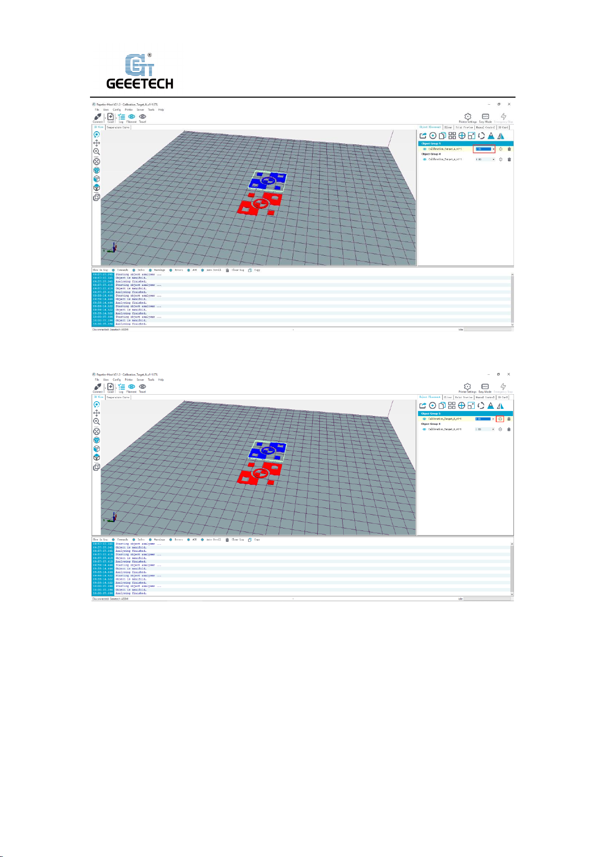
Adjust extruders to the dichromatic model in the right control frame and check the model plane
whether it touches hot bed or not so as to next printing. See picture (8-24), (8-25).
(Picture 8-24)
43
Page 44
Shenzhen Getech Technology Co.,Ltd
(Picture 8-25)
Then click the gear shape pointed by arrow to enter model info interface. See picture (8-26).
(Picture 8-26)
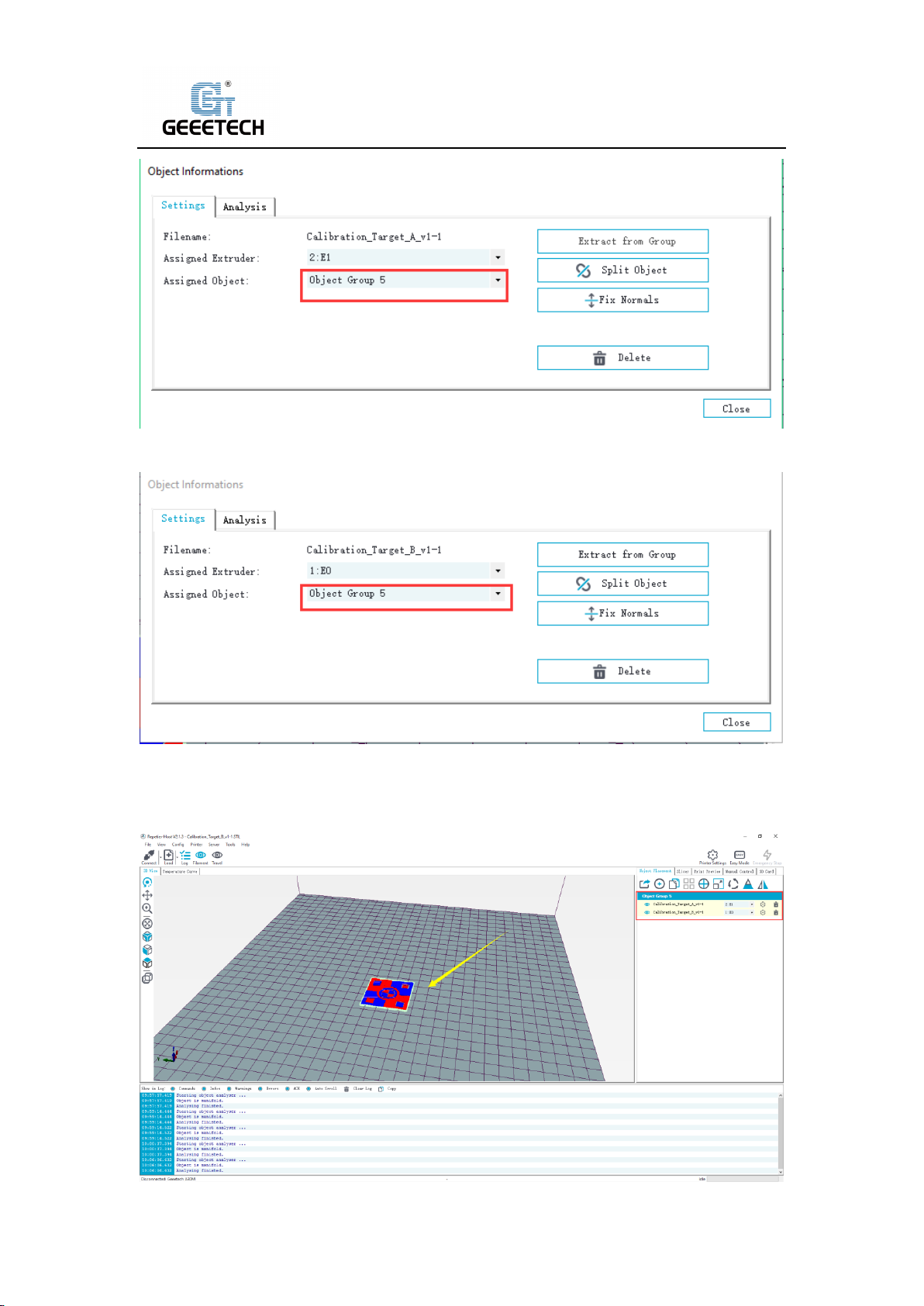
“Specified model” should be adjusted to the same as other models at picture (8-27).The both
parts of the model are within 6 default groups in our example. See picture (8-28).
44
Page 45
Shenzhen Getech Technology Co.,Ltd
(Picture 8-27)
(Picture 8-28)
At this point, the model window can see the complete model after the two partial sub-models
are merged together. See picture (8-29).
45
Page 46

Shenzhen Getech Technology Co.,Ltd
(Picture 8-29)
If the model loaded is too big and beyond the printing platform, you need to zoom out the model.
You can choose the X/Y/Z together, see picture (8-30).
(Picture 8-30)
Or zoom in/out them separately, see picture (8-31).
(Picture 8-31)
2) Model slicing
When the size and direction are set, choose the imported slicing parameter, and click “Cura
Engine”. See picture (8-32).
46
Page 47

Shenzhen Getech Technology Co.,Ltd
(Picture 8-32)
(Picture 8-33)
You can find the model information such as estimated time, the amount of filament needed, etc.
Click “Print” to start USB printing. Refer to picture (8-34).The printer will heat to the target temp
and then start printing. Under high temperature, the filament will flow out of the nozzle, which is
normal. You can use tweezers to clean up the residual material of the nozzle.
47
Page 48

Shenzhen Getech Technology Co.,Ltd
(Picture 8-34)
8.4TF card printing
When all parameters are set, click “Save for SD print”. It will pop up a dialog as picture below
(See picture 8-35) and then click the save button to generate a .gcode file. Copy the gcode file to
the TF card.
(Picture 8-35)
Insert the TF card into the slot which is on the left side of the machine. Press the knob to enter
the main menu and choose “Printing”.
48
Page 49

Shenzhen Getech Technology Co.,Ltd
(Picture 8-36)
Choose the corresponding gcode file to start printing. Click “Printing” and it will start printing.
See picture (8-37).
(Picture 8-37)
Note:
The printer can only read gcode file and the file name should be English letters, a space, an
underscore or their combination.
49
Page 50

Shenzhen Getech Technology Co.,Ltd
9Color Mixer
9.1 Download
Download address: http://www.geeetech.com/forum/viewtopic.php?f=92&t=61760
9.2 Introduction
Color Mixer enables multicolor models to be printed by adjusting the extruder discharge ratio to
the original single-color model. The specific steps are as follows:
1) Click “Import G” to import .Gco file. Choose “2” as the “Extruder Number”. See picture (9-1
and 9-2).
(Picture 9-1)
50
Page 51

Shenzhen Getech Technology Co.,Ltd
(Picture 9-2)
2) After importing the .Gco file, you can set the height of start and end layer, and the discharge
change percentage of extruders according to actual needs. You can adjust by dragging the
slider or entering a value. See picture (9-3).
3) In addition, you can click “Add” to add multiple configuration boxes to adjust the extruder
discharge change ratio at different starting and ending heights. See picture (9-4).
(Picture 9-3) (Picture 9-4)
4) See picture (9-5), Adjust discharge change ratio of each extruder in a range of heights as
needed, click the E0, E1 button in the “Preview” window in the upper right corner to enter
51
Page 52

Shenzhen Getech Technology Co.,Ltd
the color selection interface, as shown in Picture (9-6). The color here should be selected
according to the actual filament color of each extruder, and then click "Select" to confirm.
After selecting corresponding color to each extruder, click the “Preview” button below to
display color change of the current configuration in the box on the right side of the small
window.
(Picture 9-5) (Picture 9-6)
5) After configuring the parameters, click the “Mix Color” button to change the original
single-color model to a custom multicolor model. As shown in Picture (9-7).
6) Click “Export G” to export and save the mixed color model, which is named with a suffix
“_colored”. Copy the file to the TF card and insert it into the machine to start printing. See
picture (9-8, and 9-9). The processed model is shown in picture (9-10).
52
Page 53

Shenzhen Getech Technology Co.,Ltd
(picture 9-7) (picture 9-8)
(picture 9-10)
(picture 9-9)
53
Page 54

Shenzhen Getech Technology Co.,Ltd
10Function introduction
10.1Power -resuming capability
A30M has the power loss-resuming capability. When power recovery starts, it will pop up a
dialog to ask if continuing the unfinished print caused by power outage, choose “Yes “and it will
resume printing. See picture (10-1).
(Picture 10-1)
When it reaches the target temperature, the X and Y axes will auto home. The extruder will
extrude the residue in the nozzle. Use a tweezers to clean the nozzle before starting printing
again.
Note:
1) When power outage, move the nozzle away from the printing model in case the filament
oozes out on to the print.
2) Be sure to clean the residue in the nozzle before restarting the print or it would affect the
quality of the print.
10.2 Filament run-out sensor (optical)
Before using this function, first, you need to install the filament run-out senor module on the
machine and wire it. Please check filament whether it is turned on or not. Choose “Setting”>
“Filament”> “Detector”. See pictures (10-2, 10-3,10-4).
54
Page 55

Shenzhen Getech Technology Co.,Ltd
(Picture 10-2)
(Picture 10-3)
(Picture 10-4)
Be sure it shows “ON”. See picture (10-5).
55
Page 56

Shenzhen Getech Technology Co.,Ltd
(Picture 10-5)
1) It will pop up the notification “Err: No Filament” when the filament is run out during
printing and the printer will stop. See picture (10-6).
(Picture 10-6)
And at picture (10-7), if the “Filament “shows red, which indicates “No Filament”.
(Picture 10-7)
2) Press the extruder handle, remove the remaining filament before loading the new filament.
3) When the filament is loaded, please use a tweezers to clean the nozzle. Click on the button
in the lower left corner of Picture (10-8) and then it will enter printing information interface.
If the “Filament” shows green, which indicates resuming printing. You can click the left
56
Page 57

Shenzhen Getech Technology Co.,Ltd
button to start printing.
(Picture 10-8)
Note:
A30M has 2 extruders, which equipped 2 “Filament” detectors. Therefore, it would be
displayed as green only if 2 “Filament” detectors are detected at the same time in the
printing information interface.
10.33D Touch for auto bed leveling (Optical)
This printer supports auto bed leveling. Refer to the link below to know how to install the 3d
touch sensor.
Youtube:
https://www.youtube.com/watch?v=_RtsZDbR2po&t=66s
Visit our official forum:
http://www.geeetech.com/forum/
57
Page 58

Shenzhen Getech Technology Co.,Ltd
11 FAQ(Frequently Asked Questions)
11.1 Abnormal extrusion
1) The filament is tangled. The nozzle temp is too low to reach the melting temperature
required.
2) There is carbonized residue inside the nozzle.
3) Please replace it with the spare nozzle. Insufficient heat dissipation of radiator of the
extruder head causes the filament in the tube to melt in advance and the extrusion strength
is insufficient. Please check whether the cooling fan works normally.
4) The slicing speed is so fast that the nozzle speeding can’t match it. Please reduce the printing
speed.
5) Be sure the smooth in extruder inside after long-time printing. Please keep clean on a regular
basis avoiding plugging.
11.2 The gear of the extruder skips and makes an abnormal
noise
1) The nozzle is clogged; please refer to 11.1 abnormal extrusion.
2) Check whether the friction force between the extruder gear and the filament is enough.
Please clean the residue.
3) Check whether the voltage of the driver (Vref) of the extruder is normal, and try to
increase it by 0.1v until it works normally, max 1.2v.
11.3 First layer abnormal
1) Non-stick: a. the nozzle is too far from the hot bed. Please re-level the bed, try to stick
masking paper or glue stick on the surface of the hot bed.
2) Not extruding and the bed scratched: a. the nozzle is too close from the hot bed. Please
re-level the bed; b. check if the nozzle extrusion normal.
11.4 Layer shift
1) The printing speed is too fast. Please slow it down.
2) The belt of X or Y axis is too loose. Please tighten it.
3) The X or Y axis synchronization wheel is not fixed firmly. Please adjust the eccentric nuts.
4) The voltage of the driver of X/Y axis is too low.
58
Page 59

Shenzhen Getech Technology Co.,Ltd
11.5 Print stopped
1) USB printing: the signal is interfered. Please copy the model to TF card and print via TF card.
2) TF card printing: the gcode file in the TF card is abnormal, please slice again.
3) The quality of the TF card is poor. Please try another TF card.
4) The power supply voltage in the area is not stable; please print after the voltage is stable.
Visit our official forum for more information
http://www.geeetech.com/forum/viewtopic.php?f=98&t=61864)
12 Declaration
12.1 Terms
Please be advised of the following terms (the “Terms”) regarding this User Manual (this
“Manual”):
All information in this Manual is subject to change at any time without notice and is provided for
convenience purposes only. Geeetech reserves the right to modify or revise this Manual in its
sole discretion and at any time. You agree to be bound by any modifications and/or revisions.
Contact the Geeetech Support Team for up-to-date information.
12.2 Disclaimers
Neither Geeetech nor any of our affiliates warrants the accuracy or completeness of the
information, products, or services provided by or through this Manual, which are provided “as is”
and without any express or implied warranties of any kind, including warranties of merchant
ability, fitness for a particular purpose, or non-infringement of intellectual property. To the fullest
extent permissible by the applicable law, we hereby disclaim all liability for product defect or
failure or for claims that are due to normal wear, product misuse or abuse, product modification,
improper product selection, noncompliance with any codes, or misappropriation. To the fullest
extent permissible by the applicable law, we hereby disclaim any and all responsibility, risk,
liability, and damages arising out of death or personal injury resulting from assembly or operation
of our products. Geeetech assumes no responsibility, nor will be liable, for any damages to, or
any viruses or malware that may infect your computer, telecommunication equipment, or other
property caused by or arising from your downloading of any information or materials related to
Geeetech products.
59
Page 60

Shenzhen Getech Technology Co.,Ltd
Shenzhen Getech Technology Co.,Ltd
www.geeetech.com
60
 Loading...